JP2005508741A - 金属鋳造冷却システム用の完全円錐スプレーノズル - Google Patents
金属鋳造冷却システム用の完全円錐スプレーノズル Download PDFInfo
- Publication number
- JP2005508741A JP2005508741A JP2003543743A JP2003543743A JP2005508741A JP 2005508741 A JP2005508741 A JP 2005508741A JP 2003543743 A JP2003543743 A JP 2003543743A JP 2003543743 A JP2003543743 A JP 2003543743A JP 2005508741 A JP2005508741 A JP 2005508741A
- Authority
- JP
- Japan
- Prior art keywords
- liquid
- vane
- spray
- nozzle
- discharge orifice
- Prior art date
- Legal status (The legal status is an assumption and is not a legal conclusion. Google has not performed a legal analysis and makes no representation as to the accuracy of the status listed.)
- Pending
Links
Images


Classifications
-
- B—PERFORMING OPERATIONS; TRANSPORTING
- B05—SPRAYING OR ATOMISING IN GENERAL; APPLYING FLUENT MATERIALS TO SURFACES, IN GENERAL
- B05B—SPRAYING APPARATUS; ATOMISING APPARATUS; NOZZLES
- B05B1/00—Nozzles, spray heads or other outlets, with or without auxiliary devices such as valves, heating means
- B05B1/34—Nozzles, spray heads or other outlets, with or without auxiliary devices such as valves, heating means designed to influence the nature of flow of the liquid or other fluent material, e.g. to produce swirl
- B05B1/3405—Nozzles, spray heads or other outlets, with or without auxiliary devices such as valves, heating means designed to influence the nature of flow of the liquid or other fluent material, e.g. to produce swirl to produce swirl
- B05B1/341—Nozzles, spray heads or other outlets, with or without auxiliary devices such as valves, heating means designed to influence the nature of flow of the liquid or other fluent material, e.g. to produce swirl to produce swirl before discharging the liquid or other fluent material, e.g. in a swirl chamber upstream the spray outlet
- B05B1/3478—Nozzles, spray heads or other outlets, with or without auxiliary devices such as valves, heating means designed to influence the nature of flow of the liquid or other fluent material, e.g. to produce swirl to produce swirl before discharging the liquid or other fluent material, e.g. in a swirl chamber upstream the spray outlet the liquid flowing at least two different courses before reaching the swirl chamber
-
- B—PERFORMING OPERATIONS; TRANSPORTING
- B05—SPRAYING OR ATOMISING IN GENERAL; APPLYING FLUENT MATERIALS TO SURFACES, IN GENERAL
- B05B—SPRAYING APPARATUS; ATOMISING APPARATUS; NOZZLES
- B05B1/00—Nozzles, spray heads or other outlets, with or without auxiliary devices such as valves, heating means
- B05B1/34—Nozzles, spray heads or other outlets, with or without auxiliary devices such as valves, heating means designed to influence the nature of flow of the liquid or other fluent material, e.g. to produce swirl
- B05B1/3405—Nozzles, spray heads or other outlets, with or without auxiliary devices such as valves, heating means designed to influence the nature of flow of the liquid or other fluent material, e.g. to produce swirl to produce swirl
- B05B1/341—Nozzles, spray heads or other outlets, with or without auxiliary devices such as valves, heating means designed to influence the nature of flow of the liquid or other fluent material, e.g. to produce swirl to produce swirl before discharging the liquid or other fluent material, e.g. in a swirl chamber upstream the spray outlet
- B05B1/3421—Nozzles, spray heads or other outlets, with or without auxiliary devices such as valves, heating means designed to influence the nature of flow of the liquid or other fluent material, e.g. to produce swirl to produce swirl before discharging the liquid or other fluent material, e.g. in a swirl chamber upstream the spray outlet with channels emerging substantially tangentially in the swirl chamber
- B05B1/3431—Nozzles, spray heads or other outlets, with or without auxiliary devices such as valves, heating means designed to influence the nature of flow of the liquid or other fluent material, e.g. to produce swirl to produce swirl before discharging the liquid or other fluent material, e.g. in a swirl chamber upstream the spray outlet with channels emerging substantially tangentially in the swirl chamber the channels being formed at the interface of cooperating elements, e.g. by means of grooves
- B05B1/3447—Nozzles, spray heads or other outlets, with or without auxiliary devices such as valves, heating means designed to influence the nature of flow of the liquid or other fluent material, e.g. to produce swirl to produce swirl before discharging the liquid or other fluent material, e.g. in a swirl chamber upstream the spray outlet with channels emerging substantially tangentially in the swirl chamber the channels being formed at the interface of cooperating elements, e.g. by means of grooves the interface being a cylinder having the same axis as the outlet
Abstract
Description
Claims (22)
- ノズル本体を備える完全円錐液体スプレーノズルであって、
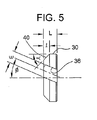
前記ノズル本体が、下流端に設けられた放出オリフィスと、上流端に設けられた、液体供給手段に接続するための入口と、当該本体を貫通して前記入口と前記放出オリフィスとの間を連通させている液体流路と、前記通路内の前記放出オリフィスの上流に配置されているベーンとを有しており、
前記液体流路が前記ベーンと前記放出オリフィスとの間に渦巻き合流チャンバを定めており、
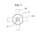
前記ベーンが、前記放出オリフィスと同軸で、軸線方向の流れを形成するための中心オリフィスと、前記中心オリフィスの周りに円周に沿って配置されている、複数の液体の流れを接線方向に向けるための少なくとも3つの角度の付いた通路とを有し、液体の渦流やブレークダウンを起こし、前記軸線方向の流れと合流させることで、前記放出オリフィスから放出される液体が、液体粒子が全体にわたって分散している円錐形スプレーパターンを有するようにするものである、完全円錐液体スプレーノズル。 - 前記ノズル本体の放出オリフィスが円形構造である、請求項1記載のスプレーノズル。
- 前記ベーンが前記液体通路内に固定されている別個のインサート部材である、請求項1記載のスプレーノズル。
- 前記ベーンが切頭円錐形の下流端を有する、請求項1記載のスプレーノズル。
- 前記角度の付いた通路が、前記ベーンの前記切頭円錐形下流端に少なくとも部分的に連通している、請求項4記載のスプレーノズル。
- 前記本体の通路と前記ベーンの切頭円錐形下流端が、前記渦巻きチャンバに連通し前記角度の付いた通路が液体を放出する、外側に拡がっている環状チャンバを定める、請求項4記載のスプレーノズル。
- 前記ベーンの切頭円錐形端が、当該ベーンの軸線方向の長さの約1/2の軸線方向の長さだけ延びている、請求項6記載のスプレーノズル。
- 前記角度の付いた通路が、前記ベーンの周りに、120°の円周上の位置に等しく間隔を空けて配置されている、請求項1記載のスプレーノズル。
- 前記角度の付いた通路が前記ベーンを貫通して直線状に延びている、請求項1記載のスプレーノズル。
- 前記角度の付いた通路がそれぞれほぼU字型の断面を有する、請求項8記載の完全円錐スプレーノズル。
- 前記ノズル本体の放出オリフィスが、渦巻きチャンバに連通しており、内側に向かって先細っている切頭円錐形の入口領域と、下流端に外側に拡がっている切頭円錐形領域とを有する、請求項1記載のスプレーノズル。
- 前記角度の付いた通路がそれぞれ所定の幅「w」と半径方向の深さ「d」を有し、当該幅「w」のほうが深さ「d」よりも大きい、請求項1記載のスプレーノズル。
- 前記角度の付いた通路がそれぞれ、前記深さ「d」の約1.2倍の幅「w」を有する、請求項12記載のスプレーノズル。
- 前記角度の付いた通路がそれぞれ、前記ベーンの中心オリフィスの流れの面積の約0.19〜0.26倍の流れの面積を定めている、請求項1記載のスプレーノズル。
- 前記放出オリフィスが、前記ベーンの中心オリフィスによって定められている流れの面積の約2.0〜2.3倍の流れの面積を定めている、請求項1記載のスプレーノズル。
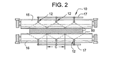
- 互いに並列に配置されている複数のスプレーノズルを備える、金属鋳造装置において冷却液を方向付けるためのスプレーシステムであって、
各ノズルが、冷却液の円錐形スプレーパターンを冷却する金属面の被覆領域へと向けるように動作可能で、隣接するノズルの放出スプレーの被覆領域は互いに部分的に重なっており、
前記ノズルがそれぞれノズル本体を備え、前記本体が、下流端に設けられた円形放出オリフィスと、当該本体を貫通して当該本体の上流端の液体の入口と前記放出オリフィスとの間を連通させている液体流路と、前記通路内の前記放出オリフィスの上流に配置されているベーンとを有しており、
前記液体流路が前記ベーンと前記放出オリフィスとの間に渦巻き合流チャンバを定めており、
前記ベーンが、当該ベーンの周りに円周に沿って配置されている少なくとも3つの角度の付いた通路を含む複数の液体流路を有し、当該角度の付いた通路は、複数の液体の流れを前記渦巻き合流チャンバへと接線方向に向けることで、前記放出オリフィスから放出される液体が、液体粒子が全体にわたって分散している円錐形スプレーパターンを有するようにするものであり、
さらに前記ノズル本体は液体供給手段を有し、当該液体供給手段は、特定の冷却の用途のために、前記スプレーノズルからスプレーされる液体の量に応じた所定の圧力範囲内の異なる圧力で、加圧された冷却液を前記ノズルへと向けるためのものでであり、
前記スプレーノズルはそれぞれ、一定の円錐形スプレー角度で円錐形スプレーパターンを放出し、前記所定の圧力範囲内で液体圧力が変化しても一定の被覆領域に衝突させるのに有効である、スプレーシステム。 - 前記ベーンが切頭円錐形下流端を有し、前記角度の付いた通路が前記ベーンの切頭円錐形下流端に少なくとも部分的に連通している、請求項16記載のスプレーノズル。
- 前記角度の付いた通路が前記ベーンを貫通して直線状に延びている、請求項16記載のスプレーノズル。
- 前記ベーンの流路が、前記角度の付いた通路によって接線方向に放出される複数の流れと合流される軸線方向の流れを形成するための、前記放出オリフィスと同軸の中心オリフィスを含む、請求項16記載のスプレーシステム。
- 互いに並列に配置されている複数のスプレーノズルを備える、金属鋳造作業において冷却液を方向付けるためのスプレーシステムであって、
各ノズルが、冷却する金属面の被覆領域に冷却液の円錐形スプレーパターンを向けるように動作可能で、隣接するノズルの放出スプレーの被覆領域は互いに部分的に重なり合う関係にあり
前記ノズルがそれぞれノズル本体を備え、当該ノズル本体が、下流端に設けられた放出オリフィスと、当該本体を貫通して当該本体の上流端にある液体の入口と前記放出オリフィスとの間を連通させている液体流路と、前記通路内の前記放出オリフィスの上流に配置されているベーンとを有しており、
前記液体流路が前記ベーンと前記放出オリフィスとの間に渦巻き合流チャンバを定めており、
前記ベーンが、前記放出オリフィスと同軸で軸線方向の流れを形成するための中心オリフィスと、前記中心オリフィスの周りに円周に沿って配置されている、複数の液体の流れを接線方向に向けるための複数の角度の付いた通路とを有し、液体の渦流やブレークダウンを起こし前記軸線方向の流れと合流させることで、前記放出オリフィスから放出される液体が、液体粒子が全体に分散している円錐形スプレーパターンを有するようにするものであり、
さらに前記本体は加圧された冷却液を前記ノズルへと向けるための液体供給手段を有しており、
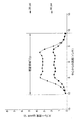
前記スプレーノズルは円錐形スプレーパターンを放出するのに有効で、液体圧力が前記所定の圧力範囲内で変化しても、ノズル本体の軸線を通るように切り取られた第1の平面セグメントにおける単位面積当たりの液体の流量が、第1の平面セグメントの被覆領域に垂直で、ノズル本体の軸線を通るように切り取られた第2の平面セグメントにおける単位面積当たりの液体の流量に実質的に近似している、スプレーシステム。 - 前記ベーンが切頭円錐形下流端を有し、前記角度の付いた通路が前記ベーンの切頭円錐形下流端に少なくとも部分的に連通している、請求項20記載のスプレーノズル。
- 前記ベーンが前記角度の付いた通路を少なくとも3つ有する、請求項20記載のスプレーシステム。
Applications Claiming Priority (2)
| Application Number | Priority Date | Filing Date | Title |
|---|---|---|---|
| US09/992,729 US6561440B1 (en) | 2001-11-14 | 2001-11-14 | Full cone spray nozzle for metal casting cooling system |
| PCT/US2002/022582 WO2003041866A1 (en) | 2001-11-14 | 2002-07-16 | Full cone spray nozzle for metal casting cooling sytsem |
Publications (2)
| Publication Number | Publication Date |
|---|---|
| JP2005508741A true JP2005508741A (ja) | 2005-04-07 |
| JP2005508741A5 JP2005508741A5 (ja) | 2006-01-05 |
Family
ID=25538673
Family Applications (1)
| Application Number | Title | Priority Date | Filing Date |
|---|---|---|---|
| JP2003543743A Pending JP2005508741A (ja) | 2001-11-14 | 2002-07-16 | 金属鋳造冷却システム用の完全円錐スプレーノズル |
Country Status (5)
| Country | Link |
|---|---|
| US (1) | US6561440B1 (ja) |
| EP (1) | EP1444047B1 (ja) |
| JP (1) | JP2005508741A (ja) |
| CN (2) | CN101036907B (ja) |
| WO (1) | WO2003041866A1 (ja) |
Cited By (4)
| Publication number | Priority date | Publication date | Assignee | Title |
|---|---|---|---|---|
| JP2009539614A (ja) * | 2006-06-05 | 2009-11-19 | スプレイング システムズ カンパニー | 連続金属鋳物冷却のためのフルコーン型エアアシスト式噴射ノズル |
| WO2014102909A1 (ja) | 2012-12-25 | 2014-07-03 | 新日鐵住金株式会社 | フルコーンスプレーノズル |
| JP2016123935A (ja) * | 2015-01-05 | 2016-07-11 | スプレーイングシステムスジャパン株式会社 | 広角フルコーンスプレーノズル |
| JP2020082323A (ja) * | 2018-11-30 | 2020-06-04 | 株式会社荏原製作所 | 研磨装置 |
Families Citing this family (25)
| Publication number | Priority date | Publication date | Assignee | Title |
|---|---|---|---|---|
| US6814307B2 (en) * | 2002-01-24 | 2004-11-09 | Combustion Components Associates, Inc. | Low NOx liquid fuel oil atomizer spray plate and fabrication method thereof |
| WO2004075839A2 (en) * | 2003-02-21 | 2004-09-10 | Irm Llc | Methods and compositions for modulating apoptosis |
| US7007739B2 (en) | 2004-02-28 | 2006-03-07 | Wagstaff, Inc. | Direct chilled metal casting system |
| JP4899335B2 (ja) * | 2005-04-26 | 2012-03-21 | 日油株式会社 | 融雪剤組成物 |
| US7793588B2 (en) * | 2005-08-22 | 2010-09-14 | Goss International Americas, Inc. | Spray pattern valve body |
| US20070045453A1 (en) * | 2005-08-23 | 2007-03-01 | Goss International Americas, Inc. | Central manifold supply for spray bar |
| US20070044670A1 (en) * | 2005-08-23 | 2007-03-01 | Goss International Americas, Inc. | Spray bar control for accomodating multiple widths |
| DE102005047195B3 (de) | 2005-09-23 | 2007-06-06 | Lechler Gmbh | Vollkegelsprühdüse |
| US8104697B2 (en) * | 2008-03-19 | 2012-01-31 | Petrovic John E | Fluid spray control device |
| US20090288798A1 (en) * | 2008-05-23 | 2009-11-26 | Nucor Corporation | Method and apparatus for controlling temperature of thin cast strip |
| US8745978B2 (en) | 2008-09-19 | 2014-06-10 | Renault Trucks | Mixing device in an exhaust gas pipe |
| JP2010240580A (ja) * | 2009-04-06 | 2010-10-28 | Victory:Kk | 液体噴射ノズルおよびシャワーヘッド |
| US10000370B2 (en) | 2010-02-05 | 2018-06-19 | Ecowell, Llc | Container-less custom beverage vending invention |
| US10017372B2 (en) | 2010-02-05 | 2018-07-10 | Ecowell, Llc | Container-less custom beverage vending invention |
| DE102010051227A1 (de) * | 2010-11-12 | 2012-05-16 | Dental Care Innovation Gmbh | Düse zur Abstrahlung von flüssigen Reinigungsmitteln mit darin dispergierten abrasiven Partikeln |
| CN102513232A (zh) * | 2012-01-06 | 2012-06-27 | 淮南同正科技有限公司 | 除尘喷雾头 |
| TWI507248B (zh) * | 2012-12-28 | 2015-11-11 | Nippon Steel & Sumitomo Metal Corp | Filled cone nozzle |
| CN103252296A (zh) * | 2013-05-28 | 2013-08-21 | 清华大学 | 喷雾喷嘴及喷雾装置 |
| CN105722603B (zh) * | 2013-09-20 | 2021-02-19 | 喷雾系统公司 | 适于流体化的催化裂化的喷雾喷嘴 |
| US9925508B2 (en) * | 2013-11-12 | 2018-03-27 | Spraying Systems Co. | Catalytic cracking spray nozzle with internal liquid particle dispersion ring |
| KR101836661B1 (ko) * | 2016-07-04 | 2018-03-08 | 현대자동차주식회사 | 철계 분말 제조장치 |
| CN106391593B (zh) * | 2016-12-10 | 2019-04-12 | 无锡银联齿轮传动机械有限公司 | 柄管镀前清洗机的清洗座 |
| USD825741S1 (en) | 2016-12-15 | 2018-08-14 | Water Pik, Inc. | Oral irrigator handle |
| CN110653077B (zh) * | 2019-10-09 | 2021-04-09 | 湖南大用环保科技有限公司 | 自清洁防堵喷嘴 |
| JP2021178319A (ja) * | 2020-05-15 | 2021-11-18 | スプレイング システムズ カンパニー | 改良型のデスケーリングノズルアセンブリ |
Family Cites Families (6)
| Publication number | Priority date | Publication date | Assignee | Title |
|---|---|---|---|---|
| US2428748A (en) * | 1944-06-22 | 1947-10-07 | Star Sprinkler Corp | Nozzle |
| DE7242476U (de) * | 1972-11-18 | 1973-04-05 | Lechler Apparatebau Kg | Vollkegelduese zum verspruehen von fluessigkeiten |
| US4474331A (en) * | 1982-09-27 | 1984-10-02 | Wm. Steinen Mfg. Co. | Recessed center vane for full cone nozzle |
| US4669667A (en) * | 1985-10-29 | 1987-06-02 | Kerr-Mcgee Chemical Corporation | Nozzle for spraying a liquid into a vessel opening |
| US5143298A (en) | 1990-10-31 | 1992-09-01 | Man Roland Druckmaschinen Ag | Spray nozzle assembly with swivel mounted hollow cone spray tip |
| US6076744A (en) | 1998-12-23 | 2000-06-20 | Spraying Systems Co. | Full cone spray nozzle |
-
2001
- 2001-11-14 US US09/992,729 patent/US6561440B1/en not_active Expired - Lifetime
-
2002
- 2002-07-16 CN CN2007100968915A patent/CN101036907B/zh not_active Expired - Lifetime
- 2002-07-16 JP JP2003543743A patent/JP2005508741A/ja active Pending
- 2002-07-16 CN CNB028268997A patent/CN1318147C/zh not_active Expired - Lifetime
- 2002-07-16 WO PCT/US2002/022582 patent/WO2003041866A1/en active Application Filing
- 2002-07-16 EP EP02759154.4A patent/EP1444047B1/en not_active Expired - Lifetime
Cited By (7)
| Publication number | Priority date | Publication date | Assignee | Title |
|---|---|---|---|---|
| JP2009539614A (ja) * | 2006-06-05 | 2009-11-19 | スプレイング システムズ カンパニー | 連続金属鋳物冷却のためのフルコーン型エアアシスト式噴射ノズル |
| WO2014102909A1 (ja) | 2012-12-25 | 2014-07-03 | 新日鐵住金株式会社 | フルコーンスプレーノズル |
| JPWO2014102909A1 (ja) * | 2012-12-25 | 2017-01-12 | 新日鐵住金株式会社 | フルコーンスプレーノズル |
| JP2016123935A (ja) * | 2015-01-05 | 2016-07-11 | スプレーイングシステムスジャパン株式会社 | 広角フルコーンスプレーノズル |
| JP2020082323A (ja) * | 2018-11-30 | 2020-06-04 | 株式会社荏原製作所 | 研磨装置 |
| JP7152279B2 (ja) | 2018-11-30 | 2022-10-12 | 株式会社荏原製作所 | 研磨装置 |
| US11839948B2 (en) | 2018-11-30 | 2023-12-12 | Ebara Corporation | Polishing apparatus |
Also Published As
| Publication number | Publication date |
|---|---|
| EP1444047A4 (en) | 2009-03-11 |
| CN1612784A (zh) | 2005-05-04 |
| EP1444047B1 (en) | 2015-08-26 |
| EP1444047A1 (en) | 2004-08-11 |
| CN101036907B (zh) | 2011-05-18 |
| US6561440B1 (en) | 2003-05-13 |
| CN1318147C (zh) | 2007-05-30 |
| US20030089800A1 (en) | 2003-05-15 |
| CN101036907A (zh) | 2007-09-19 |
| WO2003041866A1 (en) | 2003-05-22 |
Similar Documents
| Publication | Publication Date | Title |
|---|---|---|
| JP2005508741A (ja) | 金属鋳造冷却システム用の完全円錐スプレーノズル | |
| JP2005508741A5 (ja) | ||
| EP1071514B1 (en) | Spray nozzle assembly | |
| AU2007258736B2 (en) | Full cone air assisted spray nozzle for continuous metal casting cooling | |
| US8857740B2 (en) | Two-component nozzle with secondary air nozzles arranged in circular form | |
| JP5741886B2 (ja) | デスケーリング噴射ノズルアセンブリ | |
| US6142388A (en) | Atomizing nozzle | |
| US20070069049A1 (en) | Solid cone spray nozzle | |
| EP1596989B1 (en) | Air assisted spray nozzle assembly for spraying viscous liquids | |
| CZ20001760A3 (cs) | Rozprašovací tryska pro sprchování plynule odlévaných polotovarů chladicí kapalinou | |
| US20150231694A1 (en) | Spray nozzle device, in particular for spraying a cast strand | |
| CA1321809C (en) | Spray nozzles | |
| JPH0592153A (ja) | スプレーノズル アセンブリ | |
| JP6440160B2 (ja) | 広角フルコーンスプレーノズル | |
| JP2588803Y2 (ja) | 液噴射ノズル | |
| US4346724A (en) | Apparatus for spraying a coolant on a steel slab | |
| JPH0732886B2 (ja) | 気液噴霧用ノズル | |
| JPS635145B2 (ja) | ||
| JPH0617737B2 (ja) | スラリ燃料燃焼装置 |
Legal Events
| Date | Code | Title | Description |
|---|---|---|---|
| A521 | Written amendment |
Free format text: JAPANESE INTERMEDIATE CODE: A523 Effective date: 20050719 |
|
| A621 | Written request for application examination |
Free format text: JAPANESE INTERMEDIATE CODE: A621 Effective date: 20050719 |
|
| A131 | Notification of reasons for refusal |
Free format text: JAPANESE INTERMEDIATE CODE: A131 Effective date: 20071204 |
|
| A601 | Written request for extension of time |
Free format text: JAPANESE INTERMEDIATE CODE: A601 Effective date: 20080229 |
|
| A602 | Written permission of extension of time |
Free format text: JAPANESE INTERMEDIATE CODE: A602 Effective date: 20080307 |
|
| A601 | Written request for extension of time |
Free format text: JAPANESE INTERMEDIATE CODE: A601 Effective date: 20080401 |
|
| A602 | Written permission of extension of time |
Free format text: JAPANESE INTERMEDIATE CODE: A602 Effective date: 20080408 |
|
| A601 | Written request for extension of time |
Free format text: JAPANESE INTERMEDIATE CODE: A601 Effective date: 20080430 |
|
| A602 | Written permission of extension of time |
Free format text: JAPANESE INTERMEDIATE CODE: A602 Effective date: 20080509 |
|
| A521 | Written amendment |
Free format text: JAPANESE INTERMEDIATE CODE: A523 Effective date: 20080604 |
|
| A02 | Decision of refusal |
Free format text: JAPANESE INTERMEDIATE CODE: A02 Effective date: 20081118 |