JP2005508741A - Full cone spray nozzle for metal casting cooling system - Google Patents
Full cone spray nozzle for metal casting cooling system Download PDFInfo
- Publication number
- JP2005508741A JP2005508741A JP2003543743A JP2003543743A JP2005508741A JP 2005508741 A JP2005508741 A JP 2005508741A JP 2003543743 A JP2003543743 A JP 2003543743A JP 2003543743 A JP2003543743 A JP 2003543743A JP 2005508741 A JP2005508741 A JP 2005508741A
- Authority
- JP
- Japan
- Prior art keywords
- liquid
- vane
- spray
- nozzle
- discharge orifice
- Prior art date
- Legal status (The legal status is an assumption and is not a legal conclusion. Google has not performed a legal analysis and makes no representation as to the accuracy of the status listed.)
- Pending
Links
Images


Classifications
-
- B—PERFORMING OPERATIONS; TRANSPORTING
- B05—SPRAYING OR ATOMISING IN GENERAL; APPLYING FLUENT MATERIALS TO SURFACES, IN GENERAL
- B05B—SPRAYING APPARATUS; ATOMISING APPARATUS; NOZZLES
- B05B1/00—Nozzles, spray heads or other outlets, with or without auxiliary devices such as valves, heating means
- B05B1/34—Nozzles, spray heads or other outlets, with or without auxiliary devices such as valves, heating means designed to influence the nature of flow of the liquid or other fluent material, e.g. to produce swirl
- B05B1/3405—Nozzles, spray heads or other outlets, with or without auxiliary devices such as valves, heating means designed to influence the nature of flow of the liquid or other fluent material, e.g. to produce swirl to produce swirl
- B05B1/341—Nozzles, spray heads or other outlets, with or without auxiliary devices such as valves, heating means designed to influence the nature of flow of the liquid or other fluent material, e.g. to produce swirl to produce swirl before discharging the liquid or other fluent material, e.g. in a swirl chamber upstream the spray outlet
- B05B1/3478—Nozzles, spray heads or other outlets, with or without auxiliary devices such as valves, heating means designed to influence the nature of flow of the liquid or other fluent material, e.g. to produce swirl to produce swirl before discharging the liquid or other fluent material, e.g. in a swirl chamber upstream the spray outlet the liquid flowing at least two different courses before reaching the swirl chamber
-
- B—PERFORMING OPERATIONS; TRANSPORTING
- B05—SPRAYING OR ATOMISING IN GENERAL; APPLYING FLUENT MATERIALS TO SURFACES, IN GENERAL
- B05B—SPRAYING APPARATUS; ATOMISING APPARATUS; NOZZLES
- B05B1/00—Nozzles, spray heads or other outlets, with or without auxiliary devices such as valves, heating means
- B05B1/34—Nozzles, spray heads or other outlets, with or without auxiliary devices such as valves, heating means designed to influence the nature of flow of the liquid or other fluent material, e.g. to produce swirl
- B05B1/3405—Nozzles, spray heads or other outlets, with or without auxiliary devices such as valves, heating means designed to influence the nature of flow of the liquid or other fluent material, e.g. to produce swirl to produce swirl
- B05B1/341—Nozzles, spray heads or other outlets, with or without auxiliary devices such as valves, heating means designed to influence the nature of flow of the liquid or other fluent material, e.g. to produce swirl to produce swirl before discharging the liquid or other fluent material, e.g. in a swirl chamber upstream the spray outlet
- B05B1/3421—Nozzles, spray heads or other outlets, with or without auxiliary devices such as valves, heating means designed to influence the nature of flow of the liquid or other fluent material, e.g. to produce swirl to produce swirl before discharging the liquid or other fluent material, e.g. in a swirl chamber upstream the spray outlet with channels emerging substantially tangentially in the swirl chamber
- B05B1/3431—Nozzles, spray heads or other outlets, with or without auxiliary devices such as valves, heating means designed to influence the nature of flow of the liquid or other fluent material, e.g. to produce swirl to produce swirl before discharging the liquid or other fluent material, e.g. in a swirl chamber upstream the spray outlet with channels emerging substantially tangentially in the swirl chamber the channels being formed at the interface of cooperating elements, e.g. by means of grooves
- B05B1/3447—Nozzles, spray heads or other outlets, with or without auxiliary devices such as valves, heating means designed to influence the nature of flow of the liquid or other fluent material, e.g. to produce swirl to produce swirl before discharging the liquid or other fluent material, e.g. in a swirl chamber upstream the spray outlet with channels emerging substantially tangentially in the swirl chamber the channels being formed at the interface of cooperating elements, e.g. by means of grooves the interface being a cylinder having the same axis as the outlet
Abstract
冷却液を鋳造金属材の上に連続して向けるのに特に有用なスプレーノズル(12)である。このスプレーノズル(12)はノズル本体(18)を含み、このノズル本体は、放出オリフィス(22)に連通している液体流路(21)と、通路(21)内の放出オリフィス(22)の上流に配置されているベーン(30)とを有する。このベーン(30)は、軸線方向の流れを形成するための中心オリフィス(35)と、円周上に離間して配置されている、複数の液体の流れを接線方向に向けるための複数の角度の付いた通路(36)とを有し、液体の渦流やブレークダウンを起こし、軸線方向の流れと合流させることで、放出オリフィス(21)から放出される液体が、金属が鋳造される速度の変化に比例する液体圧力の変化にも関わらず、鋳造金属のより均一な冷却のために用いられるようにするものである。A spray nozzle (12) that is particularly useful for directing cooling liquid onto the cast metal. The spray nozzle (12) includes a nozzle body (18) that includes a liquid flow path (21) in communication with the discharge orifice (22) and a discharge orifice (22) in the passage (21). And a vane (30) disposed upstream. The vane (30) has a central orifice (35) for forming an axial flow, and a plurality of angles that are spaced apart on the circumference and direct a plurality of liquid flows in a tangential direction. A passage (36) with a vortex and breakdown of the liquid, and by joining the axial flow, the liquid discharged from the discharge orifice (21) has a speed at which the metal is cast. It is intended to be used for more uniform cooling of the cast metal despite the change in liquid pressure proportional to the change.
Description
本発明は一般にスプレーノズルに関し、特に、金属鋳造作業において冷却液をスプレーするのに特に有用な完全円錐液体スプレーノズル(full cone liquid spray nozzle )に関する。 The present invention relates generally to spray nozzles, and more particularly to full cone liquid spray nozzles that are particularly useful for spraying coolant in metal casting operations.
金属鋳造作業、特に鋼スラブ、ビレット又は他の金属材を型から押出す連続金属鋳造システムでは、現れる金属に水をスプレーして素早く熱を取り去ることが必要となる。均一な冷却のためには、このスプレーが細かな霧状とされ金属の上に均一に向けられるのが望ましい。冷却液の分散が不均一であると金属の冷却も不均一となり、裂けを生じたり、高い応力がかかったり、表面やエッジの品質が下がったりする。 In metal casting operations, particularly continuous metal casting systems that extrude steel slabs, billets or other metal materials from a mold, it is necessary to quickly remove heat by spraying water on the metal that appears. For uniform cooling, it is desirable for the spray to be a fine mist and be evenly directed onto the metal. If the dispersion of the cooling liquid is not uniform, the cooling of the metal will also be uneven, resulting in tearing, high stress, and poor surface and edge quality.
冷却液、即ち水を金属の表面に向け、加圧された空気によって溶解しないように最大限の冷却を行うために、連続金属鋳造作業では完全円錐液体スプレーノズルが使われてきた。従来の完全円錐スプレーノズルは典型的にノズル本体を備え、この本体は放出オリフィスと上流ベーンとを有する。この上流ベーンは、ノズルを通過する液体に渦巻き運動を起こして液体の流れを分解し、液体粒子を放出される円錐形スプレーパターン全体にわたって分散させるためのものである。しかしながら従来の完全円錐スプレーノズルには、動作上の欠点がある。 Full conical liquid spray nozzles have been used in continuous metal casting operations to direct cooling liquid, i.e. water, to the surface of the metal and provide maximum cooling so that it is not dissolved by pressurized air. Conventional full conical spray nozzles typically include a nozzle body that has a discharge orifice and an upstream vane. This upstream vane is intended to cause a vortex motion in the liquid passing through the nozzle to break up the liquid flow and disperse the liquid particles throughout the conical spray pattern being released. However, conventional full cone spray nozzles have operational disadvantages.
従来の完全円錐液体スプレーノズルの1つの問題は、液体の通過量が液体の圧力によって完全に制御されているという理由から生じている。適切な冷却を行うためには、連続鋳造作業でスプレーされる液体の量が、金属材が鋳造される速度に比例していなければならない。換言すると、金属がより早い速度で型から現れる場合、適切な冷却のためには、速度のより遅い鋳造におけるよりも多量の冷却剤が必要になる。しかしながら従来の完全円錐スプレーノズルでは、スプレーの量を変えるために必要な液体の圧力を変えると、放出される円錐形スプレーの角度も変わってしまい、ひいてはスプレーの被覆領域、即ち液体が衝突する金属表面上の領域も変化してしまう。スプレーの被覆領域が変わってしまうと、隣接するノズルが放出するスプレーが重なる範囲が変わってしまうことによって冷却の均一性が変化し、隣接するノズルが放出するスプレーの間に間隙ができてしまう場合もある。 One problem with conventional full cone liquid spray nozzles arises because the amount of liquid passing is completely controlled by the pressure of the liquid. In order to provide proper cooling, the amount of liquid sprayed in a continuous casting operation must be proportional to the rate at which the metal material is cast. In other words, if the metal emerges from the mold at a faster rate, a greater amount of coolant is required for proper cooling than in a slower casting. However, with conventional full cone spray nozzles, changing the pressure of the liquid required to change the amount of spray will also change the angle of the cone spray emitted, and thus the spray coating area, ie the metal that the liquid impinges on. The area on the surface will also change. If the spray coverage changes, the range of overlapping sprays emitted from adjacent nozzles changes, which changes the uniformity of cooling and creates a gap between the sprays emitted by adjacent nozzles. There is also.
連続金属鋳造作業で従来の完全円錐液体スプレーノズルを使用することに関するさらなる問題は、放出されるスプレーが、スプレー圧力に関わらず元来不均一であるということである。試験によると、スプレーノズルの軸線に平行なある狭い平面セグメントに沿って単位面積当たりで収集した液体の量(即ち、液体の密度)が、第1の平面セグメントに垂直で、ノズルの軸線を通る第2の狭い平面セグメントで測定した液体の密度とは実質的に異なることが示されている。もしスプレーノズルがある所定の関係で互いに取り付けられているのならばこのような不均一性が考慮されているのかもしれないが、スプレーノズルは典型的に供給管にねじ止めされているだけなので、あるノズルの不規則なスプレーパターンは隣接するノズルの不規則なスプレーパターンとは無関係である。このことによって、移動している鋳造金属の冷却が一層不均一になり得る。 A further problem with using conventional full cone liquid spray nozzles in continuous metal casting operations is that the spray delivered is inherently non-uniform regardless of spray pressure. According to tests, the amount of liquid collected per unit area (ie, liquid density) along a narrow planar segment parallel to the spray nozzle axis is perpendicular to the first planar segment and passes through the nozzle axis. It has been shown that the density of the liquid measured in the second narrow planar segment is substantially different. This non-uniformity may be considered if the spray nozzles are attached to each other in a certain relationship, but the spray nozzles are typically only screwed into the supply tube. The irregular spray pattern of one nozzle is independent of the irregular spray pattern of adjacent nozzles. This can make the cooling of the cast metal that is moving more uneven.
本発明の目的は、より均一な液体のスプレー、ひいてはより均一な金属の冷却に適した完全円錐液体スプレーノズルを有する鋳造金属液体スプレーシステムを提供することである。 It is an object of the present invention to provide a cast metal liquid spray system having a full conical liquid spray nozzle suitable for more uniform liquid spraying and thus more uniform metal cooling.
本発明の別の目的は、放出されるスプレーの液体スプレー量を、冷却の均一性に悪影響を及ぼさずに、金属鋳造作業の速度に応じて簡単に変えることができる、完全円錐液体スプレーノズルを提供することである。 Another object of the present invention is to provide a fully conical liquid spray nozzle that can easily change the liquid spray volume of the discharged spray depending on the speed of the metal casting operation without adversely affecting the cooling uniformity. Is to provide.
本発明のさらに別の目的は、放出される円錐形スプレーの角度、ひいてはスプレーの被覆領域が液体圧力の変化の影響を実質的に受けない、上記のように特徴付けられた完全円錐スプレーノズルを提供することである。 Yet another object of the present invention is to provide a fully conical spray nozzle characterized as described above, wherein the angle of the cone spray discharged, and thus the coating area of the spray, is substantially unaffected by changes in liquid pressure. Is to provide.
本発明のさらに別の目的は、放出されるスプレーの液体密度が、互いに垂直でノズルの軸線を通る平面セグメントを含むスプレーパターン全体にわたって実質的に同様な、上述の種類の完全円錐液体スプレーノズルを提供することである。 Yet another object of the present invention is to provide a fully conical liquid spray nozzle of the type described above wherein the liquid density of the emitted spray is substantially similar across the entire spray pattern including plane segments perpendicular to each other and passing through the axis of the nozzle. Is to provide.
本発明のさらに別の目的は、構造が比較的単純で、経済的な製造と信頼性のある使用に適した、上述の型の完全円錐液体スプレーノズルを提供することである。 Yet another object of the present invention is to provide a full conical liquid spray nozzle of the type described above which is relatively simple in construction and suitable for economical manufacture and reliable use.
本発明の他の目的及び利点は、以下の詳細な説明を読み図面を参照することによって明らかになるであろう。 Other objects and advantages of the present invention will become apparent upon reading the following detailed description and upon reference to the drawings in which:
本発明は種々の変更や代替的な構造が可能であるが、本発明のある1つの例示的な実施形態を図面に示し、以下に詳細に説明する。しかしながら本発明を開示する特定の形態に制限する意図はなく、むしろ本発明がその趣旨や範囲内に存在する全ての変更、代替的な構造及び等価を包含することがその意図であることを理解されたい。 While the invention is susceptible to various modifications and alternative constructions, certain exemplary embodiments thereof are shown in the drawings and are described in detail below. However, it is not intended that the invention be limited to the particular forms disclosed, but rather that the intention is that the invention encompasses all modifications, alternative constructions, and equivalents that fall within the spirit and scope of the invention. I want to be.
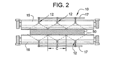
図面をより具体的に参照すると、本発明を具現化した完全円錐液体スプレーノズル12を備えるスプレーシステム10を有する例示的な連続金属鋳造装置が示されている。この連続鋳造装置は公知の型のものでよく、連続鋳型(図示せず)を含み、この場合スラブ14の形態の金属材がこの鋳型から押出される。この場合スラブ14は連続鋳造機から現れ、現れる金属材の両側に回転可能に支持されているガイドローラ15、16の平行なセットによって垂直方向から水平方向へと向きが変えられる。複数のスプレーノズル12がローラ15、16の各対の間の列にそれぞれ支持されており、円錐形の液体スプレー、即ち水を金属材14の両面へと向ける。従来技術において公知であるように、各列のスプレーノズル12は共通の液体マニホールド供給管17によって支持されており、移動している金属材の面ができる限り均一に冷却されるように隣接するスプレーノズルアセンブリから放出されるスプレーパターンが重なるように、取り付けられている。各スプレーノズル12は構造が類似しているため、1つだけを詳細に説明すればよい。
Referring more specifically to the drawings, an exemplary continuous metal casting apparatus having a
図3に示すように、各スプレーノズル12は細長い中空本体18を備えている。この本体は、供給ライン又は管20へと接続するために外側にねじ切りされた端部19を有し、そして典型的にはこの供給ライン又は管20の上流が、スプレーノズルアセンブリの列のための供給マニホールドへと接続している。ノズル本体18と供給管20の継手とをレンチで締めやすくするために、六角形の頭部23がノズル本体18の下流端に隣接して形成されている。ノズル本体18は、液体供給管20と連通している軸線方向の液体通路21と、ノズル本体の下流端に円形放出オリフィス22とを有する。放出オリフィス22はこの場合円筒形に構成されており、内側に向かって先細っていく切頭円錐形の入口領域24と、出口端には比較的小さく外側へと拡がっている切頭円錐形の領域25とを有する。
As shown in FIG. 3, each
ノズル本体18を通過する液体に渦巻き運動をさせ、またこの液体を粒子にまで分解し、放出オリフィス22から放出される完全円錐液体スプレーパターン全体にわたって分散させるために、ベーン30が通路21内のノズル本体18の上流端と放出オリフィス22との中間に設けられている。この場合のベーン30は、液体通路21内に圧入される別個の部材又はインサートである。通路21がベーン30と放出オリフィス22との間にほぼ円筒形の渦巻き合流チャンバ31を定めるように、ベーン30を放出オリフィス22の上流の長手方向の所定の位置に確実に配置するために、通路21には、ベーン30が配置される位置決めシート32を定める小さなカウンタボアが形成されている。ベーン30が緩くなったときにノズル本体18から不用意に外れないように、ノズル本体18には入口通路21の上流端の周りに内側に向いた放射状の戻り止め34が形成されている。
In order to swirl the liquid passing through the
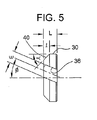
本発明によるとノズルベーンは固有の構造を有する。この構造は、液体をブレークダウン(breakdown)し易くし、この液体を放出される完全円錐スプレーパターン全体にわたってほぼ均一に分散させ易くすることで、連続鋳造作業における移動中の金属材の均等な冷却を改善するものである。このためにベーン30は、液体の通過量の中心部分を通すための軸線方向の中心通路35と、中心の流れと合流する、接線方向に向けられた複数の流れを形成するための少なくとも3つの角度の付いた通路36とを有する。例示されているベーン30は、ベーンを通って軸線方向に延びている円筒形開口の形態の中心通路35と、ベーンの周縁の周りに円周に沿って120°ずつ離間して配置されている3つの角度の付いた通路36とを有する。角度の付いた通路36はこの場合、ベーン30の外周に形成された外側に開いた矩形又はU字型のスロットによって定められている。角度の付いた通路36を通過する液体を接線方向に向けるために、角度の付いた通路36にはそれぞれ、スプレーノズルの長手軸線に対して約25°の出口角度Φが付けられている。製造し易くするために、角度の付いた通路36を定めるスロットは、長手軸線に対して一定の角度Φでベーンを貫通して直線状に延びている。
According to the present invention, the nozzle vane has a unique structure. This construction facilitates the breakdown of the liquid and facilitates the uniform cooling of the moving metal in continuous casting operations by facilitating the distribution of the liquid almost uniformly throughout the discharged full cone spray pattern. Is to improve. To this end, the
例示のベーン30では、角度の付いた通路36は深さ「d」よりもやや広い幅「w」を有する。角度の付いたベーンの通路の幅「w」は深さ「d」の約1.2倍であることが好ましい。また、角度の付いたベーンの通路36はそれぞれ、ベーンの中心通路35の面積の約0.19〜0.26倍の流れの面積を定めるのが好ましく、ベーンの中心通路35の流れの面積の約0.2〜0.25倍の流れの面積を有するのが好ましい。ノズル本体18の放出オリフィス22は、ベーンの中心通路35の流れの面積の約2.0〜2.3倍の流れの面積を有するのが好ましい。例示のベーンは3つの角度の付いた通路36を有するが、ノズル本体18のサイズや詰まりを起こし得る冷却液中の固体物質に依っては、4つ又はそれより多くの、数に応じてより小さくなった、角度の付いた通路を有してもよい。
In the
本発明をふまえると、渦巻き合流チャンバ31内で液体をブレークダウンし合流し易くするために、ベーン30は内側にテーパ付された切頭円錐形の下流端40を有する。このことによって、角度の付いた通路36はそれぞれ液体の一部を、ベーン30の内側にテーパ付された端部40によって定められている、下方に拡がるテーパ付チャンバ41と、渦巻き合流チャンバ31を取り囲む円筒形の壁に放出することができる。ベーンの切頭円錐形端40はこの場合45°の角度αを有し、ベーンの長さ「L」の約1/2の軸線方向の長さ「l」を有する。理由は十分には分かっていないが、複数の角度の付いた通路31からテーパ付環状チャンバ41へと放出される液体の流れは、放出オリフィス22へと送られそこから放出される前に、液体粒子によりよくブレークダウンされてベーンの中心通路35から放出される流れとよりよく合流される。
In view of the present invention, the
スプレーシステム11の動作では、ノズル本体18の入口通路21へと向けられた加圧液体がベーン30を通過し、その一部が中心通路35を通るように軸線方向に向けられ、複数の流れが角度の付いた通路36を通るように接線方向に向けられる。複数の液体の流れは合流チャンバ31でブレークダウンされて合流され、次いで液体スプレー粒子がスプレーパターン全体にわたって分散されている完全円錐液体スプレーパターン44で放出オリフィス22から放出される。例示の実施形態では、液体は、65°〜75°の円錐形のスプレー角度βを有する円錐形スプレーパターン44で放出し、図2に示すように現れる鋳造金属材の領域「c」、即ち被覆領域に衝突する。先に述べたように、スプレーノズル12は、隣接するノズルのスプレー被覆領域「c」が互いに部分的に重なるように配置されている。
In the operation of the spray system 11, the pressurized liquid directed to the
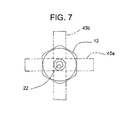
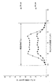
本発明をふまえると、スプレーノズルから向けられる液体の量は、ある有効な圧力範囲内で入口の液体圧力を変化させることで、放出される円錐形スプレーのスプレー角度βに影響を及ぼさずに、つまり放出されるスプレーの被覆領域「c」、即ち放出されるスプレーが金属面に衝突する領域を実質的に変えずに、簡単に調整することができる。放出される円錐形スプレーの円錐形スプレー角度β、つまりスプレーの被覆領域「c」は、入口の液体圧力が実質的に変わってもほとんど変わらないままである。例えば図8は、本発明を表すスプレーノズルを20psiと80psiの液体圧力で作動させたときの単位面積当たりの流量、即ちスプレー密度を示している。この場合液体は、ノズルの軸線を通る平面のセグメント45a(図7を参照のこと)で収集した。高い液体圧力で作動させた場合は、低い入口の液体圧力で作動させたときよりも高いスプレー密度が得られるが、放出される円錐形スプレーの被覆領域「c」は、どちらの圧力でもほぼ同一であることが分かる。
In view of the present invention, the amount of liquid directed from the spray nozzle does not affect the spray angle β of the cone spray emitted by varying the inlet liquid pressure within a certain effective pressure range, That is, the coating area “c” of the spray to be ejected, that is, the area where the spray to be ejected collides with the metal surface can be adjusted easily without substantially changing. The cone spray angle β of the discharged cone spray, ie the spray coverage area “c”, remains substantially unchanged even if the inlet liquid pressure changes substantially. For example, FIG. 8 shows the flow rate per unit area, or spray density, when a spray nozzle representing the present invention is operated at liquid pressures of 20 psi and 80 psi. In this case, the liquid was collected in a
対照的に図9は、これまで本出願人が販売してきた従来技術の完全円錐スプレーノズルモデル1/4HHX−8フルジェット(Full Jet)の性能を示している。液体圧力が高いとスプレー密度も高くなるが、スプレーノズルを10psiで作動させた場合のスプレーの被覆領域「c−1」は、このノズルを60psiで作動させた場合のスプレーの被覆領域「c−2」よりも実質的に狭い。その結果スプレーノズルをこのように低い液体圧力で作動させた場合、隣接するノズルのスプレー被覆の重なりは、より高い液体圧力での動作時に得られる重なりよりも実質的に狭い。さらにスプレーノズルの間隔によっては、隣接するスプレーノズルのスプレー被覆領域の間に望ましくない間隙を生じることもあり得る。どちらの場合でも、均一な冷却に悪影響を及ぼし得る。
In contrast, FIG. 9 shows the performance of the prior art full cone
さらに本発明をふまえると、本発明のノズル12から放出される円錐形スプレーの液体の分散は、スプレーパターン全体にわたってほぼ近似している。例えば図8は、スプレーノズルの軸線を通る、比較的狭い平面セグメント45a(図7を参照のこと)で測定した単位面積当たりの流量、即ちスプレー密度を示している。試験によって、平面セグメント45aに垂直な、ノズルの軸線を通る平面セグメント45b(図7)における円錐形スプレーの液体分散もほぼ同一であることが分かる。換言すると、この分散は平面セグメントの角度的な向きが変わっても、スプレーパターン全体にわたって同じままである。したがってノズルアセンブリを液体供給管上にねじ止めすると、ノズル本体が供給管に対してねじ止めされた回転位置に関わらず、隣接するノズルの液体分散はほぼ近似している。
Further in accordance with the present invention, the dispersion of the conical spray liquid emitted from the
対照的に図9は、本出願人の従来技術による1/4HHX−8フルジェットノズルを60psiで作動させた場合の、単位面積当たりの流量を示している。ノズル本体の軸線を通るように切り取った第1の平面セグメントにおける液体分散(実線で示す)が、第1の平面セグメントに垂直で、ノズル本体の軸線を通る第2の平面セグメントで測定した液体分散(仮想線で示す)に対して実質的に変化していることが分かる。このようなスプレーノズルによる冷却の不均一さは、隣接するノズルが供給管に対して別々の回転位置でそれぞれの供給管にねじ止めされている場合に特に顕著である。
In contrast, FIG. 9 shows the flow rate per unit area when Applicant's
上記の説明から、本発明のスプレーシステムが連続鋳造作業における金属材のより均一で有効な冷却に適しており、鋳造金属により優れた表面とエッジの品質を与えることが分かる。さらに、液体スプレーノズルを通るスプレー量は、入口の液体圧力を変えることで、冷却の均一性に悪影響を及ぼさずに簡単に変えることができる。さらにこのスプレーノズルアセンブリによって、互いに垂直に配置された、ノズルの軸線を通る平面セグメントにおける液体密度又は分散パターンがほぼ近似している、実質的に近似しているスプレーパターンが形成される。さらに当業者ならば、スプレーノズルの構造が比較的単純で、経済的な製造と信頼性のある使用に適していることを理解するであろう。 From the above description, it can be seen that the spray system of the present invention is suitable for more uniform and effective cooling of the metal material in continuous casting operations and gives the cast metal superior surface and edge quality. Furthermore, the amount of spray through the liquid spray nozzle can be easily changed by changing the inlet liquid pressure without adversely affecting the cooling uniformity. In addition, the spray nozzle assembly forms a substantially approximate spray pattern that is approximately similar to the liquid density or dispersion pattern in planar segments disposed perpendicular to each other and passing through the axis of the nozzle. Furthermore, those skilled in the art will appreciate that the structure of the spray nozzle is relatively simple and suitable for economical manufacturing and reliable use.
Claims (22)
前記ノズル本体が、下流端に設けられた放出オリフィスと、上流端に設けられた、液体供給手段に接続するための入口と、当該本体を貫通して前記入口と前記放出オリフィスとの間を連通させている液体流路と、前記通路内の前記放出オリフィスの上流に配置されているベーンとを有しており、
前記液体流路が前記ベーンと前記放出オリフィスとの間に渦巻き合流チャンバを定めており、
前記ベーンが、前記放出オリフィスと同軸で、軸線方向の流れを形成するための中心オリフィスと、前記中心オリフィスの周りに円周に沿って配置されている、複数の液体の流れを接線方向に向けるための少なくとも3つの角度の付いた通路とを有し、液体の渦流やブレークダウンを起こし、前記軸線方向の流れと合流させることで、前記放出オリフィスから放出される液体が、液体粒子が全体にわたって分散している円錐形スプレーパターンを有するようにするものである、完全円錐液体スプレーノズル。 A fully conical liquid spray nozzle with a nozzle body,
The nozzle body has a discharge orifice provided at the downstream end, an inlet provided at the upstream end for connection to the liquid supply means, and communicates between the inlet and the discharge orifice through the main body. A liquid flow path, and a vane disposed upstream of the discharge orifice in the passage,
The liquid flow path defines a vortex merge chamber between the vane and the discharge orifice;
The vane is coaxial with the discharge orifice and has a central orifice for forming an axial flow and a circumferential arrangement around the central orifice for directing a plurality of liquid flows tangentially And at least three angled passages for causing liquid vortices and breakdowns to merge with the axial flow so that the liquid discharged from the discharge orifice has liquid particles throughout. A full conical liquid spray nozzle intended to have a distributed conical spray pattern.
各ノズルが、冷却液の円錐形スプレーパターンを冷却する金属面の被覆領域へと向けるように動作可能で、隣接するノズルの放出スプレーの被覆領域は互いに部分的に重なっており、
前記ノズルがそれぞれノズル本体を備え、前記本体が、下流端に設けられた円形放出オリフィスと、当該本体を貫通して当該本体の上流端の液体の入口と前記放出オリフィスとの間を連通させている液体流路と、前記通路内の前記放出オリフィスの上流に配置されているベーンとを有しており、
前記液体流路が前記ベーンと前記放出オリフィスとの間に渦巻き合流チャンバを定めており、
前記ベーンが、当該ベーンの周りに円周に沿って配置されている少なくとも3つの角度の付いた通路を含む複数の液体流路を有し、当該角度の付いた通路は、複数の液体の流れを前記渦巻き合流チャンバへと接線方向に向けることで、前記放出オリフィスから放出される液体が、液体粒子が全体にわたって分散している円錐形スプレーパターンを有するようにするものであり、
さらに前記ノズル本体は液体供給手段を有し、当該液体供給手段は、特定の冷却の用途のために、前記スプレーノズルからスプレーされる液体の量に応じた所定の圧力範囲内の異なる圧力で、加圧された冷却液を前記ノズルへと向けるためのものでであり、
前記スプレーノズルはそれぞれ、一定の円錐形スプレー角度で円錐形スプレーパターンを放出し、前記所定の圧力範囲内で液体圧力が変化しても一定の被覆領域に衝突させるのに有効である、スプレーシステム。 A spray system for directing coolant in a metal casting apparatus comprising a plurality of spray nozzles arranged in parallel to each other,
Each nozzle is operable to direct a conical spray pattern of coolant to a coated area of the metal surface that cools, the discharge areas of adjacent nozzles partially overlapping each other;
Each of the nozzles includes a nozzle body, and the body communicates between a circular discharge orifice provided at a downstream end and a liquid inlet at the upstream end of the main body and the discharge orifice through the main body. A liquid flow path, and a vane disposed upstream of the discharge orifice in the passage;
The liquid flow path defines a vortex merge chamber between the vane and the discharge orifice;
The vane has a plurality of liquid flow paths including at least three angled passages disposed circumferentially around the vane, the angled passages comprising a plurality of liquid flows. Tangentially into the vortex merge chamber so that the liquid discharged from the discharge orifice has a conical spray pattern in which liquid particles are dispersed throughout;
Furthermore, the nozzle body has liquid supply means, the liquid supply means at different pressures within a predetermined pressure range depending on the amount of liquid sprayed from the spray nozzle for a specific cooling application, For directing pressurized coolant to the nozzle,
Each of the spray nozzles emits a conical spray pattern at a constant conical spray angle and is effective to impinge on a constant coating area even if the liquid pressure changes within the predetermined pressure range .
各ノズルが、冷却する金属面の被覆領域に冷却液の円錐形スプレーパターンを向けるように動作可能で、隣接するノズルの放出スプレーの被覆領域は互いに部分的に重なり合う関係にあり
前記ノズルがそれぞれノズル本体を備え、当該ノズル本体が、下流端に設けられた放出オリフィスと、当該本体を貫通して当該本体の上流端にある液体の入口と前記放出オリフィスとの間を連通させている液体流路と、前記通路内の前記放出オリフィスの上流に配置されているベーンとを有しており、
前記液体流路が前記ベーンと前記放出オリフィスとの間に渦巻き合流チャンバを定めており、
前記ベーンが、前記放出オリフィスと同軸で軸線方向の流れを形成するための中心オリフィスと、前記中心オリフィスの周りに円周に沿って配置されている、複数の液体の流れを接線方向に向けるための複数の角度の付いた通路とを有し、液体の渦流やブレークダウンを起こし前記軸線方向の流れと合流させることで、前記放出オリフィスから放出される液体が、液体粒子が全体に分散している円錐形スプレーパターンを有するようにするものであり、
さらに前記本体は加圧された冷却液を前記ノズルへと向けるための液体供給手段を有しており、
前記スプレーノズルは円錐形スプレーパターンを放出するのに有効で、液体圧力が前記所定の圧力範囲内で変化しても、ノズル本体の軸線を通るように切り取られた第1の平面セグメントにおける単位面積当たりの液体の流量が、第1の平面セグメントの被覆領域に垂直で、ノズル本体の軸線を通るように切り取られた第2の平面セグメントにおける単位面積当たりの液体の流量に実質的に近似している、スプレーシステム。 A spray system for directing coolant in a metal casting operation, comprising a plurality of spray nozzles arranged in parallel to each other,
Each nozzle is operable to direct a conical spray pattern of cooling liquid onto the coating area of the metal surface to be cooled, and the discharge spray coating areas of adjacent nozzles are in a partially overlapping relationship with each other. A liquid flow path comprising a main body, wherein the nozzle main body communicates between the discharge orifice provided at the downstream end and the liquid inlet and the discharge orifice penetrating the main body at the upstream end of the main body And a vane disposed upstream of the discharge orifice in the passageway,
The liquid flow path defines a vortex merge chamber between the vane and the discharge orifice;
A central orifice for forming an axial flow coaxial with the discharge orifice and a circumferential direction around the central orifice for directing a plurality of liquid flows tangentially; A plurality of angled passages, and by causing liquid vortex and breakdown to merge with the axial flow, the liquid discharged from the discharge orifice is dispersed throughout the liquid particles. Is intended to have a conical spray pattern
Furthermore, the main body has a liquid supply means for directing the pressurized coolant to the nozzle,
The spray nozzle is effective to emit a conical spray pattern, and the unit area in the first planar segment cut through the axis of the nozzle body even when the liquid pressure changes within the predetermined pressure range The permeate liquid flow rate is substantially similar to the liquid flow rate per unit area in a second planar segment that is perpendicular to the coverage area of the first planar segment and cut through the axis of the nozzle body. There is a spray system.
21. The spray system of claim 20, wherein the vane has at least three of the angled passages.
Applications Claiming Priority (2)
| Application Number | Priority Date | Filing Date | Title |
|---|---|---|---|
| US09/992,729 US6561440B1 (en) | 2001-11-14 | 2001-11-14 | Full cone spray nozzle for metal casting cooling system |
| PCT/US2002/022582 WO2003041866A1 (en) | 2001-11-14 | 2002-07-16 | Full cone spray nozzle for metal casting cooling sytsem |
Publications (2)
| Publication Number | Publication Date |
|---|---|
| JP2005508741A true JP2005508741A (en) | 2005-04-07 |
| JP2005508741A5 JP2005508741A5 (en) | 2006-01-05 |
Family
ID=25538673
Family Applications (1)
| Application Number | Title | Priority Date | Filing Date |
|---|---|---|---|
| JP2003543743A Pending JP2005508741A (en) | 2001-11-14 | 2002-07-16 | Full cone spray nozzle for metal casting cooling system |
Country Status (5)
| Country | Link |
|---|---|
| US (1) | US6561440B1 (en) |
| EP (1) | EP1444047B1 (en) |
| JP (1) | JP2005508741A (en) |
| CN (2) | CN1318147C (en) |
| WO (1) | WO2003041866A1 (en) |
Cited By (4)
| Publication number | Priority date | Publication date | Assignee | Title |
|---|---|---|---|---|
| JP2009539614A (en) * | 2006-06-05 | 2009-11-19 | スプレイング システムズ カンパニー | Full cone type air assist type injection nozzle for continuous metal casting cooling |
| WO2014102909A1 (en) | 2012-12-25 | 2014-07-03 | 新日鐵住金株式会社 | Full cone spray nozzle |
| JP2016123935A (en) * | 2015-01-05 | 2016-07-11 | スプレーイングシステムスジャパン株式会社 | Wide angle full cone spray nozzle |
| JP2020082323A (en) * | 2018-11-30 | 2020-06-04 | 株式会社荏原製作所 | Polishing device |
Families Citing this family (25)
| Publication number | Priority date | Publication date | Assignee | Title |
|---|---|---|---|---|
| US6814307B2 (en) * | 2002-01-24 | 2004-11-09 | Combustion Components Associates, Inc. | Low NOx liquid fuel oil atomizer spray plate and fabrication method thereof |
| US20050003387A1 (en) * | 2003-02-21 | 2005-01-06 | Irm Llc | Methods and compositions for modulating apoptosis |
| US7007739B2 (en) | 2004-02-28 | 2006-03-07 | Wagstaff, Inc. | Direct chilled metal casting system |
| JP4899335B2 (en) * | 2005-04-26 | 2012-03-21 | 日油株式会社 | Snow melting composition |
| US7793588B2 (en) * | 2005-08-22 | 2010-09-14 | Goss International Americas, Inc. | Spray pattern valve body |
| US20070045453A1 (en) * | 2005-08-23 | 2007-03-01 | Goss International Americas, Inc. | Central manifold supply for spray bar |
| US20070044670A1 (en) * | 2005-08-23 | 2007-03-01 | Goss International Americas, Inc. | Spray bar control for accomodating multiple widths |
| DE102005047195B3 (en) | 2005-09-23 | 2007-06-06 | Lechler Gmbh | Solid cone spray nozzle |
| US8104697B2 (en) * | 2008-03-19 | 2012-01-31 | Petrovic John E | Fluid spray control device |
| US20090288798A1 (en) * | 2008-05-23 | 2009-11-26 | Nucor Corporation | Method and apparatus for controlling temperature of thin cast strip |
| EP2342434B1 (en) * | 2008-09-19 | 2012-08-15 | Renault Trucks | Mixing device in an exhaust gas pipe |
| JP2010240580A (en) * | 2009-04-06 | 2010-10-28 | Victory:Kk | Liquid injection nozzle and shower head |
| US10017372B2 (en) | 2010-02-05 | 2018-07-10 | Ecowell, Llc | Container-less custom beverage vending invention |
| US10000370B2 (en) | 2010-02-05 | 2018-06-19 | Ecowell, Llc | Container-less custom beverage vending invention |
| DE102010051227A1 (en) * | 2010-11-12 | 2012-05-16 | Dental Care Innovation Gmbh | Nozzle for the emission of liquid cleaning agents with abrasive particles dispersed therein |
| CN102513232A (en) * | 2012-01-06 | 2012-06-27 | 淮南同正科技有限公司 | Dedusting spray head |
| TWI507248B (en) * | 2012-12-28 | 2015-11-11 | Nippon Steel & Sumitomo Metal Corp | Filled cone |
| CN103252296A (en) * | 2013-05-28 | 2013-08-21 | 清华大学 | Spraying nozzle and spraying device |
| US10095830B2 (en) * | 2013-09-20 | 2018-10-09 | Spraying Systems Co. | Spray nozzle for fluidized catalytic cracking |
| CN106232239A (en) * | 2013-11-12 | 2016-12-14 | 喷雾系统公司 | There is the catalytic cracking spray nozzle of internal liquid granule central dispersion |
| KR101836661B1 (en) * | 2016-07-04 | 2018-03-08 | 현대자동차주식회사 | Manufacturing apparatus of iron powder |
| CN106391593B (en) * | 2016-12-10 | 2019-04-12 | 无锡银联齿轮传动机械有限公司 | The toilet seat of handle pipe cleaning before copper plating machine |
| USD825741S1 (en) | 2016-12-15 | 2018-08-14 | Water Pik, Inc. | Oral irrigator handle |
| CN110653077B (en) * | 2019-10-09 | 2021-04-09 | 湖南大用环保科技有限公司 | Self-cleaning anti-blocking nozzle |
| JP2021178319A (en) * | 2020-05-15 | 2021-11-18 | スプレイング システムズ カンパニー | Improved descaling nozzle assembly |
Family Cites Families (6)
| Publication number | Priority date | Publication date | Assignee | Title |
|---|---|---|---|---|
| US2428748A (en) * | 1944-06-22 | 1947-10-07 | Star Sprinkler Corp | Nozzle |
| DE7242476U (en) * | 1972-11-18 | 1973-04-05 | Lechler Apparatebau Kg | FULL CONE NOZZLE FOR SPRAYING LIQUIDS |
| US4474331A (en) * | 1982-09-27 | 1984-10-02 | Wm. Steinen Mfg. Co. | Recessed center vane for full cone nozzle |
| US4669667A (en) * | 1985-10-29 | 1987-06-02 | Kerr-Mcgee Chemical Corporation | Nozzle for spraying a liquid into a vessel opening |
| US5143298A (en) | 1990-10-31 | 1992-09-01 | Man Roland Druckmaschinen Ag | Spray nozzle assembly with swivel mounted hollow cone spray tip |
| US6076744A (en) | 1998-12-23 | 2000-06-20 | Spraying Systems Co. | Full cone spray nozzle |
-
2001
- 2001-11-14 US US09/992,729 patent/US6561440B1/en not_active Expired - Lifetime
-
2002
- 2002-07-16 CN CNB028268997A patent/CN1318147C/en not_active Expired - Lifetime
- 2002-07-16 WO PCT/US2002/022582 patent/WO2003041866A1/en active Application Filing
- 2002-07-16 CN CN2007100968915A patent/CN101036907B/en not_active Expired - Lifetime
- 2002-07-16 EP EP02759154.4A patent/EP1444047B1/en not_active Expired - Lifetime
- 2002-07-16 JP JP2003543743A patent/JP2005508741A/en active Pending
Cited By (7)
| Publication number | Priority date | Publication date | Assignee | Title |
|---|---|---|---|---|
| JP2009539614A (en) * | 2006-06-05 | 2009-11-19 | スプレイング システムズ カンパニー | Full cone type air assist type injection nozzle for continuous metal casting cooling |
| WO2014102909A1 (en) | 2012-12-25 | 2014-07-03 | 新日鐵住金株式会社 | Full cone spray nozzle |
| JPWO2014102909A1 (en) * | 2012-12-25 | 2017-01-12 | 新日鐵住金株式会社 | Full cone spray nozzle |
| JP2016123935A (en) * | 2015-01-05 | 2016-07-11 | スプレーイングシステムスジャパン株式会社 | Wide angle full cone spray nozzle |
| JP2020082323A (en) * | 2018-11-30 | 2020-06-04 | 株式会社荏原製作所 | Polishing device |
| JP7152279B2 (en) | 2018-11-30 | 2022-10-12 | 株式会社荏原製作所 | Polishing equipment |
| US11839948B2 (en) | 2018-11-30 | 2023-12-12 | Ebara Corporation | Polishing apparatus |
Also Published As
| Publication number | Publication date |
|---|---|
| EP1444047A1 (en) | 2004-08-11 |
| US20030089800A1 (en) | 2003-05-15 |
| EP1444047A4 (en) | 2009-03-11 |
| CN101036907B (en) | 2011-05-18 |
| US6561440B1 (en) | 2003-05-13 |
| EP1444047B1 (en) | 2015-08-26 |
| CN1318147C (en) | 2007-05-30 |
| CN101036907A (en) | 2007-09-19 |
| CN1612784A (en) | 2005-05-04 |
| WO2003041866A1 (en) | 2003-05-22 |
Similar Documents
| Publication | Publication Date | Title |
|---|---|---|
| JP2005508741A (en) | Full cone spray nozzle for metal casting cooling system | |
| JP2005508741A5 (en) | ||
| EP1071514B1 (en) | Spray nozzle assembly | |
| AU2007258736B2 (en) | Full cone air assisted spray nozzle for continuous metal casting cooling | |
| US8857740B2 (en) | Two-component nozzle with secondary air nozzles arranged in circular form | |
| JP5741886B2 (en) | Descaling injection nozzle assembly | |
| US6142388A (en) | Atomizing nozzle | |
| US20070069049A1 (en) | Solid cone spray nozzle | |
| EP1596989B1 (en) | Air assisted spray nozzle assembly for spraying viscous liquids | |
| CZ20001760A3 (en) | Spray nozzle for rinsing continuously half-finished products with cooling liquid | |
| US20150231694A1 (en) | Spray nozzle device, in particular for spraying a cast strand | |
| CA1321809C (en) | Spray nozzles | |
| JPH0592153A (en) | Spray nozzle assembly | |
| JP6440160B2 (en) | Wide angle full cone spray nozzle | |
| JP2588803Y2 (en) | Liquid injection nozzle | |
| US4346724A (en) | Apparatus for spraying a coolant on a steel slab | |
| JPH0732886B2 (en) | Gas-liquid spray nozzle | |
| JPS635145B2 (en) | ||
| JPH0617737B2 (en) | Slurry fuel combustion device |
Legal Events
| Date | Code | Title | Description |
|---|---|---|---|
| A521 | Written amendment |
Free format text: JAPANESE INTERMEDIATE CODE: A523 Effective date: 20050719 |
|
| A621 | Written request for application examination |
Free format text: JAPANESE INTERMEDIATE CODE: A621 Effective date: 20050719 |
|
| A131 | Notification of reasons for refusal |
Free format text: JAPANESE INTERMEDIATE CODE: A131 Effective date: 20071204 |
|
| A601 | Written request for extension of time |
Free format text: JAPANESE INTERMEDIATE CODE: A601 Effective date: 20080229 |
|
| A602 | Written permission of extension of time |
Free format text: JAPANESE INTERMEDIATE CODE: A602 Effective date: 20080307 |
|
| A601 | Written request for extension of time |
Free format text: JAPANESE INTERMEDIATE CODE: A601 Effective date: 20080401 |
|
| A602 | Written permission of extension of time |
Free format text: JAPANESE INTERMEDIATE CODE: A602 Effective date: 20080408 |
|
| A601 | Written request for extension of time |
Free format text: JAPANESE INTERMEDIATE CODE: A601 Effective date: 20080430 |
|
| A602 | Written permission of extension of time |
Free format text: JAPANESE INTERMEDIATE CODE: A602 Effective date: 20080509 |
|
| A521 | Written amendment |
Free format text: JAPANESE INTERMEDIATE CODE: A523 Effective date: 20080604 |
|
| A02 | Decision of refusal |
Free format text: JAPANESE INTERMEDIATE CODE: A02 Effective date: 20081118 |