JP2005299280A - Mobile scaffolding system - Google Patents
Mobile scaffolding system Download PDFInfo
- Publication number
- JP2005299280A JP2005299280A JP2004119150A JP2004119150A JP2005299280A JP 2005299280 A JP2005299280 A JP 2005299280A JP 2004119150 A JP2004119150 A JP 2004119150A JP 2004119150 A JP2004119150 A JP 2004119150A JP 2005299280 A JP2005299280 A JP 2005299280A
- Authority
- JP
- Japan
- Prior art keywords
- scaffold
- maintenance
- beam member
- panel
- outer frame
- Prior art date
- Legal status (The legal status is an assumption and is not a legal conclusion. Google has not performed a legal analysis and makes no representation as to the accuracy of the status listed.)
- Granted
Links
- 238000012423 maintenance Methods 0.000 claims abstract description 56
- 230000008439 repair process Effects 0.000 claims abstract description 29
- 239000000725 suspension Substances 0.000 claims abstract description 22
- 241000282693 Cercopithecidae Species 0.000 claims description 32
- 210000000988 bone and bone Anatomy 0.000 claims description 26
- 229910052782 aluminium Inorganic materials 0.000 claims description 4
- XAGFODPZIPBFFR-UHFFFAOYSA-N aluminium Chemical compound [Al] XAGFODPZIPBFFR-UHFFFAOYSA-N 0.000 claims description 4
- 230000008859 change Effects 0.000 claims description 2
- 229910052751 metal Inorganic materials 0.000 description 7
- 239000002184 metal Substances 0.000 description 7
- 238000010276 construction Methods 0.000 description 6
- 240000001549 Ipomoea eriocarpa Species 0.000 description 3
- 235000005146 Ipomoea eriocarpa Nutrition 0.000 description 3
- 230000008878 coupling Effects 0.000 description 2
- 238000010168 coupling process Methods 0.000 description 2
- 238000005859 coupling reaction Methods 0.000 description 2
- 230000006872 improvement Effects 0.000 description 2
- 239000000463 material Substances 0.000 description 2
- 230000002265 prevention Effects 0.000 description 2
- 229910001335 Galvanized steel Inorganic materials 0.000 description 1
- 229910000831 Steel Inorganic materials 0.000 description 1
- 125000004122 cyclic group Chemical group 0.000 description 1
- 238000005516 engineering process Methods 0.000 description 1
- 238000009408 flooring Methods 0.000 description 1
- 239000008397 galvanized steel Substances 0.000 description 1
- XEEYBQQBJWHFJM-UHFFFAOYSA-N iron Substances [Fe] XEEYBQQBJWHFJM-UHFFFAOYSA-N 0.000 description 1
- 229910052742 iron Inorganic materials 0.000 description 1
- 230000007246 mechanism Effects 0.000 description 1
- 238000004904 shortening Methods 0.000 description 1
- 239000010959 steel Substances 0.000 description 1
Images

Landscapes
- Bridges Or Land Bridges (AREA)
- Movable Scaffolding (AREA)
Abstract
【課題】 高架道路や橋梁などの高層構築物に対して、主として保守・維持管理・修理作業などを行う際に用いる仮設の足場装置を全面に吊設する移動足場システムの提供。
【解決手段】 構築物の保守・維持管理・修理作業などを行う箇所の下方に、構築物の長さ方向に沿って配設される対をなす断面H形状の梁部材30と、梁部材30に架設される作業床50と、作業床50に乗った作業者により梁部材30の下面に沿って連続して着脱可能のレール部材40と、梁部材30及びレール部材40に架設され、長方形状の足場パネル10をワイヤ61を介して揚上し、作業床50を介して梁部材30及びレール部材40に沿って移動可能のウインチ装置60と、ウインチ装置60により搬送された足場パネル10を、クランプ71及び吊りチェーン70を介して梁部材30に吊持する吊持手段と、隣設された足場パネル10相互を連結する連結手段と、を備え、構築物の保守・維持管理・修理作業などを行う箇所の下方全面に足場パネル10を吊設して作業を行う。
【選択図】図6PROBLEM TO BE SOLVED: To provide a mobile scaffold system for suspending a temporary scaffold device mainly used for maintenance / maintenance / repair work for a high-rise structure such as an elevated road or a bridge.
A beam member 30 having an H-shaped cross-section, which is arranged along the length direction of the structure, and a beam member 30 installed below a place where maintenance, maintenance, repair work, etc. of the structure is performed. Working floor 50, a rail member 40 that can be continuously attached and detached along the lower surface of the beam member 30 by a worker on the work floor 50, and a rectangular scaffold that is constructed on the beam member 30 and the rail member 40. The panel 10 is lifted through the wire 61, the winch device 60 movable along the beam member 30 and the rail member 40 through the work floor 50, and the scaffold panel 10 conveyed by the winch device 60 are clamped 71 And a means for suspending the beam member 30 via the suspension chain 70 and a connecting means for connecting the adjacent scaffold panels 10 to each other, and performing maintenance, maintenance, repair work, etc. of the structure of The scaffold panel 10 is suspended from the entire lower surface to perform the work.
[Selection] Figure 6
Description
本発明は、移動足場システムに関し、詳しくは、高架道路や橋梁などの高層構築物に対して、主として保守・維持管理・修理作業などを行う際に用いる仮設の足場装置を、保守・維持管理・修理作業などを行う箇所の下方全面に吊設する移動足場システムに関する。 The present invention relates to a mobile scaffold system, and more specifically, a temporary scaffold device used mainly for maintenance / maintenance / repair work for a high-rise structure such as an elevated road or a bridge, is maintained / maintained / repaired. The present invention relates to a moving scaffold system that is hung on the entire lower surface of a place where work is performed.
従来、高架道路や橋梁などの高層構築物に対して、主として保守・維持管理・修理作業などを行う際に用いる仮設の足場装置を、該高層構築物の保守・維持管理・修理作業などを行う箇所の下方に吊設する移動足場システムが周知である。この種のシステムのうち、足場パネルについて、例えば特許文献1に、1)枠体に、その枠体全面にわたって床材が取り付けられ、その床材の一部が開閉可能な蓋機構とされて、その蓋によって開閉される収納空間が形成されている、2)上記収納空間が上記枠体の長手方向両端部にそれぞれ設けられ、それら収納空間内に、上記長手方向に伸長する互いに平行な2本の吊りパイプがそれぞれ配設されている、3)上記枠体の対向2長辺にそれぞれ複数の吊り金具が配列されて取り付けられている、4)上記床材の一部が透光性を有する材料よりなる、構成が開示されている。 Conventionally, temporary scaffolding devices used mainly for maintenance, maintenance, repair work, etc. for high-rise structures such as elevated roads and bridges are used for maintenance, maintenance management, repair work, etc. of the high-rise structures. A moving scaffold system suspended below is well known. Among these types of systems, for scaffold panels, for example, in Patent Document 1, 1) a floor is attached to the entire frame, and a part of the floor is a lid mechanism that can be opened and closed. A storage space that is opened and closed by the lid is formed. 2) The storage spaces are provided at both ends in the longitudinal direction of the frame body, and two parallel ones extending in the longitudinal direction are provided in the storage spaces. 3) A plurality of hanging brackets are arranged and attached to the two opposite long sides of the frame body, respectively. 4) A part of the flooring material is translucent. An arrangement of materials is disclosed.
これら改良された足場パネルは、高架道路や橋梁などの維持、修繕に用いる仮設工事の足場装置として主要部をなすものであるが、足場パネル自体を更に改良すると共に、足場装置を高架道路や橋梁などの維持、修繕作業場所に効率よく搬送して架設し、安全に作業が行えるようにし、また、作業終了後に速やかに移動・撤去できる移動足場システムを構築することが望まれている。 These improved scaffold panels form the main part as scaffolding equipment for temporary construction used for the maintenance and repair of elevated roads and bridges, but the scaffolding panels themselves are further improved and the scaffolding equipment is replaced with elevated roads and bridges. It is desired to construct a mobile scaffolding system that can be efficiently transported and erected to maintenance and repair work sites, etc., so that the work can be performed safely, and can be moved and removed quickly after the work is completed.
工事現場の環境は多様に変化しており、施工技術も部分的には格段の進歩と変化が起きている。特に、安全と作業環境の改善については、全ての工事において進化が加速している。しかし、作業足場については、依然として固定式が主流であり、最近になって移動式が採用されるようになってはいるが、実用化されているのはごくわずかである。また、足場パネルについても、上記先行技術のように改良が進められているが、新しい移動足場システムに適用するには、さらに改良する必要がある。 The environment of the construction site is changing in various ways, and the construction technology is partly changing and changing in part. In particular, improvements in safety and work environment are accelerating in all construction. However, as for the work scaffold, the fixed type is still the mainstream, and although the mobile type has recently been adopted, only a few have been put into practical use. In addition, the scaffold panel has been improved as in the above prior art, but it needs to be further improved to be applied to a new mobile scaffold system.
本発明は、上記の問題点を解決するためになされたもので、マルチムーブシステムとして、安全・作業環境改善・省力化・工期の短縮等を図るために、従来にない新しい移動足場システムを提供することを目的とする。また、このような移動足場システムに適用できる足場パネルを提供することを目的とする。 The present invention was made to solve the above problems, and as a multi-move system, provides an unprecedented new mobile scaffolding system for safety, work environment improvement, labor saving, shortening of construction period, etc. The purpose is to do. It is another object of the present invention to provide a scaffold panel applicable to such a mobile scaffold system.
上記の目的を達成するために本発明は、請求項1〜5に記載の手段、構成を有することを特徴としている。
A.高架道路や橋梁などの高層構築物に対して、主として保守・維持管理・修理作業などを行う際に用いる仮設の足場装置を、該高層構築物の保守・維持管理・修理作業などを行う箇所の下方に吊設する移動足場システムであって、
構築物の保守・維持管理・修理作業などを行う箇所の下方に、構築物の長さ方向に沿って配設される対をなす断面H形状の梁部材と、該梁部材に架設される作業床と、該作業床に乗った作業者により前記梁部材の下面に沿って連続して着脱可能のレール部材と、該梁部材及びレール部材に架設され、長方形状の足場パネルをワイヤを介して揚上し、前記作業床を介して梁部材及びレール部材に沿って移動可能のウインチ装置と、該ウインチ装置により搬送された足場パネルを、クランプ及び吊りチェーンを介して梁部材に吊持する吊持手段と、隣設された足場パネル相互を連結する連結手段と、を備え、構築物の保守・維持管理・修理作業などを行う箇所の下方全面に足場パネルを吊設して作業を行う。
In order to achieve the above object, the present invention is characterized by having the means and configuration described in claims 1 to 5.
A. Temporary scaffolding equipment used mainly for maintenance / maintenance / repair work on high-rise structures such as elevated roads and bridges is located below the place where maintenance / maintenance / repair work for such high-rise structures is performed. A mobile scaffolding system to hang,
A beam member having an H-shaped cross section that forms a pair disposed along the length direction of the structure below a place where maintenance, maintenance, repair work, etc. of the structure is performed, and a work floor installed on the beam member A rail member that can be continuously attached and detached along the lower surface of the beam member by an operator on the work floor, and the beam member and the rail member, and a rectangular scaffold panel is lifted via a wire. And a winch device movable along the beam member and the rail member via the work floor, and a suspension means for suspending the scaffold panel conveyed by the winch device to the beam member via a clamp and a suspension chain And a connecting means for connecting the adjacent scaffold panels to each other. The scaffold panel is suspended from the entire lower surface of the place where maintenance, maintenance, repair work, etc. of the structure is performed.
B.前記作業床は、梁部材及びレール部材に対して、手動操作による移動、または自動的に移動可能であり、モンキーラック及び該モンキーラックから張り出し可能の張り出し作業部を備えている。
C.前記足場パネルは、外周に配設された外枠と、該外枠内の長さ方向に配設された横中骨と、長さ方向の外枠及び横中骨と直交するようにほぼ所定間隔に配設された複数の縦中骨と、該外枠、横中骨及び縦中骨の表面に張設されたアルミチェッカープレートからなる表面板と、からなり、長さ方向両側端部に、足場パネルの全幅より狭く、表面板の一部を開閉可能の開閉蓋とした収納庫を設け、該収納庫の両側に、両側に間隙を有して吊り用パイプを設けた。
B. The work floor can be moved manually or automatically with respect to the beam member and the rail member, and includes a monkey rack and an overhanging working section that can be overhanged from the monkey rack.
C. The scaffold panel is substantially predetermined so as to be orthogonal to the outer frame disposed on the outer periphery, the transverse middle bone disposed in the length direction in the outer frame, and the outer frame and the transverse middle bone in the length direction. A plurality of longitudinal central bones arranged at intervals, and a surface plate made of an aluminum checker plate stretched on the outer frame, the lateral central bone and the surface of the longitudinal central bone, at both ends in the longitudinal direction The storage was provided with an opening / closing lid that was narrower than the entire width of the scaffolding panel, and a part of the surface plate could be opened and closed, and suspension pipes were provided on both sides of the storage with gaps on both sides.
D.前記足場パネルは、表面板の一部を透光性の板体とし、外枠と縦中骨が交差して固着される各位置に、上下移動して使用位置と収納位置とに変更可能のU字状をした吊り金具を設け、該吊り金具と隣設される吊り金具との間の外枠に、環状金具が着脱可能のジョイント部材を設けた。
E.前記足場パネルは、外枠の長辺部に、隣設する足場パネルに対し連結、連結解除可能の連結部材を設けた。
D. The scaffold panel is a translucent plate part of the surface plate, and can be moved up and down to each position where the outer frame and the longitudinal central bone are crossed and fixed to change the use position and the storage position. A U-shaped hanging metal fitting is provided, and a joint member to which the annular metal fitting is detachable is provided on the outer frame between the hanging metal fitting and the adjacent hanging metal fitting.
E. The said scaffold panel provided the connection member which can be connected and disconnected with respect to the adjacent scaffold panel in the long side part of the outer frame.
イ.構築物の保守・維持管理・修理作業などを行う箇所の下方に対をなす梁部材を設け、該梁部材に架設された作業床に乗った作業者によって、梁部材の下面にレール部材を取付け、該梁部材及びレール部材にウインチ装置を架設するので、ウインチ装置により足場パネルを揚上し、該ウインチ装置及び足場パネルを、作業床を介して梁部材及びレール部材に沿って移動することができる。また、ウインチ装置により搬送された足場パネルを、作業床に乗った作業者によりクランプ及び吊りチェーンを介して梁部材に吊持することができる。さらに、搬送された足場パネルを、隣設する足場パネル同士を相互に連結することができ、これら足場パネルを構築物の保守・維持管理・修理作業などを行う箇所の下方全面に吊設することにより、作業中に下方への落下物を防止して安全な作業を行うことができる。 A. A pair of beam members is provided below the place where maintenance, maintenance management, repair work, etc. of the structure is performed, and a rail member is attached to the lower surface of the beam member by an operator who rides on the work floor laid on the beam member, Since the winch device is installed on the beam member and the rail member, the scaffold panel can be lifted by the winch device, and the winch device and the scaffold panel can be moved along the beam member and the rail member via the work floor. . Moreover, the scaffold panel conveyed by the winch device can be suspended on the beam member by a worker on the work floor via a clamp and a suspension chain. Furthermore, the scaffold panels that have been transported can be connected to each other adjacent to each other, and these scaffold panels can be suspended all over the area where maintenance, maintenance, repair work, etc. are performed. During the work, it is possible to prevent a falling object from falling downward and perform a safe work.
ロ.作業床は、梁部材及びレール部材に対して、手動操作による移動、または自動的に移動可能であり、足場パネルを効率よく搬送することができる。また、モンキーラック及び該モンキーラックから張り出し可能の張り出し作業部を備えているので、梁部材へのレール部材の着脱が容易に行えると共に、足場パネルを、クランプ及び吊りチェーンを介して梁部材に吊持することができる。
ハ.足場パネルは、外枠と、該外枠内に配設された横中骨と、長さ方向の外枠及び横中骨と直交するように所定間隔で配設された複数の縦中骨と、該外枠、横中骨及び縦中骨の表面に張設されたアルミチェッカープレートからなる表面板と、からなるので、足場パネルを大型でありながら軽量に構成することができる。また、足場パネルの長さ方向両側端部に、足場パネルの全幅より狭く、表面板の一部を開閉可能の開閉蓋とした収納庫を設けたので、この収納庫にクランプや吊りチェーン、ターンバックル等を収納しておき、必要なときに取り出して使用すことができる。さらに、収納庫の両側に設けた吊り用パイプは、足場パネルを吊り下げる際に用いることができる。
B. The work floor can be moved manually or automatically with respect to the beam member and the rail member, and can efficiently transport the scaffold panel. In addition, since the monkey rack and the projecting working portion that can be projected from the monkey rack are provided, the rail member can be easily attached to and detached from the beam member, and the scaffold panel is suspended from the beam member via the clamp and the suspension chain. Can have.
C. The scaffold panel includes an outer frame, a transverse middle bone arranged in the outer frame, and a plurality of longitudinal middle bones arranged at predetermined intervals so as to be orthogonal to the outer frame and the transverse middle bone in the length direction. The outer frame, the surface plate made of an aluminum checker plate stretched on the surface of the horizontal and vertical ribs, and the scaffold panel can be made lightweight while being large. In addition, a storage cabinet with an opening / closing lid that is narrower than the entire width of the scaffold panel and that can be opened and closed at a part of the surface plate is provided at both ends in the longitudinal direction of the scaffold panel. A buckle or the like can be stored and taken out when necessary. Furthermore, the suspension pipes provided on both sides of the storage can be used when the scaffold panel is suspended.
ニ.足場パネルの表面板の一部を透光性の板体としたときには、足場パネルを構築物の保守・維持管理・修理作業などを行う箇所の下方全面に吊設した場合でも、透光性の板体が明かり取りとなって、足場パネル上で安全に作業を行うことができる。また、外枠と縦中骨が交差して固着される各位置に、上下移動可能の吊り金具を設け、該吊り金具と隣設される吊り金具との間に、環状金具を着脱可能に設けたので、足場パネルをワイヤや吊りチェーンで吊り下げるときに、最も適した位置の吊り金具、または環状金具を選択してバランス良く吊持することができる。
ホ.足場パネルは、外枠の長辺部に、隣設する足場パネルに対し連結、連結解除可能の連結部材を設けたので、隣設する足場パネル相互を連結して足場パネルを安定して吊設することができ、また、足場パネル間から物が落下することがない。
D. When a part of the surface plate of the scaffold panel is made of a translucent plate, the translucent plate is used even when the scaffold panel is suspended all over the place where maintenance, maintenance, repair work, etc. of the structure is performed. The body is lighted and work can be done safely on the scaffold panel. In addition, a lifting bracket that can be moved up and down is provided at each position where the outer frame and the longitudinal center cross and fix each other, and an annular bracket is detachably provided between the hanging bracket and the adjacent hanging bracket. Therefore, when suspending the scaffold panel with a wire or a suspension chain, it is possible to suspend the scaffold panel in a balanced manner by selecting the most suitable suspension bracket or annular bracket.
E. Since the scaffolding panel is provided on the long side of the outer frame with a connecting member that can be connected to and disconnected from the adjacent scaffolding panel, the scaffolding panels can be stably suspended by connecting the adjacent scaffolding panels together. In addition, no objects can fall from between the scaffold panels.
以下、本発明を実施するための最良の形態について、添付の図面を参照しながら具体的に説明する。
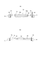
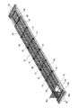
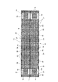
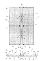
図1の(a)は、本発明による足場パネルの表面板を一部省略した平面図、(b)は、足場パネルの側面図、図2の(a)は、図1(b)のA−A線に沿う拡大断面図、(b)は、図1(b)のB−B線に沿う拡大断面図、図3は、本発明による足場パネルの全体斜視図、図4は、本発明による足場パネルを2枚連結した状態の平面図、図5の(a)は、本発明による2枚の足場パネルを連結した状態の部分平面図、(b)は、図4の矢印C方向から見た端面図、図6は、本発明による手動式足場パネル搬送システムの斜視図、図7は、本発明による自動式足場パネル搬送システムの斜視図である。
The best mode for carrying out the present invention will be specifically described below with reference to the accompanying drawings.
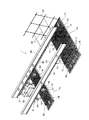
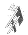
FIG. 1A is a plan view in which the surface plate of the scaffold panel according to the present invention is partially omitted, FIG. 1B is a side view of the scaffold panel, and FIG. 2A is A in FIG. FIG. 3B is an enlarged sectional view taken along line BB in FIG. 1B, FIG. 3 is an overall perspective view of a scaffold panel according to the present invention, and FIG. FIG. 5A is a partial plan view of a state in which two scaffold panels according to the present invention are connected, and FIG. 5B is a partial plan view of FIG. 6 is a perspective view of a manual scaffold panel transport system according to the present invention, and FIG. 7 is a perspective view of an automatic scaffold panel transport system according to the present invention.
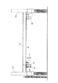
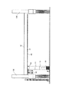
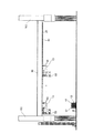
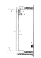
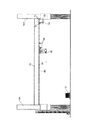
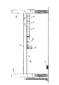
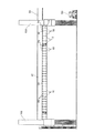
図8は、梁部材の一端側に作業床としてのモンキーラックを架設して該梁部材の下面にレール部材としてのラック部材を取付け、このラック部材を梁部材の全長に連続して取付ける状態の側面図、図9は、ラック部材を取付けた梁部材にモンキーラック及び移動装置を備えたウインチ装置を接近して架設し、ウインチ装置により2枚連結した足場パネルを揚上する状態の側面図、図10は、ウインチ装置により揚上した2枚連結した足場パネルをウインチ装置と共にモンキーラックにより移動させて梁部材の他端側に搬送する状態の側面図、図11は、梁部材の他端側に搬送した2枚連結の足場パネルを、吊りチェーンを介して梁部材のフランジに吊持する状態の側面図、図12は、2枚連結した足場パネルを吊りチェーンを介して梁部材に吊持し、ウインチ装置をモンキーラックにより梁部材の一端側に戻す状態の側面図、図13は、梁部材の他端側に吊持された足場パネルに続いて、モンキーラック及びウインチ装置により搬送されてくる足場パネルを連続して梁部材に吊持する状態の側面図、図14は、梁部材の全長に足場パネルを吊持し、モンキーラック及びウインチ装置を梁部材から下ろした状態の側面図である。 FIG. 8 shows a state in which a monkey rack as a work floor is installed on one end side of a beam member, a rack member as a rail member is attached to the lower surface of the beam member, and this rack member is continuously attached to the entire length of the beam member. Side view, FIG. 9 is a side view of a state in which a winch device provided with a monkey rack and a moving device is installed close to a beam member to which a rack member is attached, and two scaffold panels connected by the winch device are lifted, FIG. 10 is a side view showing a state in which two connected scaffold panels lifted by the winch device are moved together with the winch device by the monkey rack and conveyed to the other end side of the beam member, and FIG. 11 is the other end side of the beam member. FIG. 12 is a side view showing a state in which the two-connected scaffold panel conveyed to the flange of the beam member is suspended through the suspension chain. FIG. FIG. 13 is a side view of a state in which the winch device is returned to one end side of the beam member by the monkey rack, and FIG. 13 is conveyed by the monkey rack and winch device following the scaffold panel suspended on the other end side of the beam member. FIG. 14 is a side view of a state in which the scaffolding panel is continuously suspended from the beam member, and FIG. 14 is a side view of the state in which the monkey rack and winch device are lowered from the beam member. It is.
図1〜図3において、符号10は本発明に係る長方形をした足場パネルで、この足場パネル10は、既存の高架道路や橋梁などの高層構築物に対して、主として保守・維持管理・修理作業などを行う際に用いる仮設の足場装置として、後述する移動足場システムによって、前記高層構築物の保守・維持管理・修理作業などを行う箇所の下方に吊設されて使用される。該足場パネル10は、基本モジュール(幅1m×長さ8m×厚さ0.1m)8m2 の一体型成形品で、外周に配設された外枠11と、該外枠11内の長さ方向に配設された横中骨12と、長さ方向の外枠11及び横中骨12と直交するようにほぼ所定間隔に配設された複数の縦中骨13と、該外枠11、横中骨12及び縦中骨13の表面に張設されたアルミチェッカープレートからなる表面板14とにより構成されている。外枠11、横中骨12、縦中骨13等は溶融亜鉛メッキ処理の鋼製角パイプが使用され、自重は230kgで、大型軽量のものである。
1 to 3,
また、足場パネル10は、外枠11と縦中骨13が交差して固着される各位置に、上下移動して使用位置と収納位置とに突没可能のU字状をした吊り金具15を設け、該吊り金具15と隣設される吊り金具15との中間の外枠11、及び短辺の外枠11に、環状金具17が着脱可能のナットからなるジョイント部材16を設けている。さらに、足場パネル10の長さ方向両側端部に、該足場パネル10の全幅より狭く、表面板14の一部を、ヒンジ18bを介して開閉可能に枢支した開閉蓋18cを有する有底の収納部18aを備えた、60cm×70cmの大きさの収納庫18を設けている。該収納庫18の両側に、両側に間隙を有する長さ70cm、φ48.6の鋼管からなる吊り用パイプ19を設けている。また、収納庫18及び吊り用パイプ19,19の外側には、横中骨の短辺12a,12aを介して外枠11の短辺部が支持されている。
In addition, the
前記収納庫18には、後述するクランプや吊りチェーン、ターンバックル等が収納されて、足場パネル10を梁部材30に吊持する吊り下げ作業時に、開閉蓋18cを開けて取り出して使用する。また、前記表面板14は、その一部をプラスチック板のような、透光性の板体にしても良いものである。このように、表面板14の一部を透光性の板体にした場合には、足場パネル10を高層構築物の保守・維持管理・修理作業などを行う箇所の下方に敷き詰めたときに明かり取りとなって、特に照明をしなくても安全に作業を行うことができる。
The
図4及び図5において、足場パネル10には、外枠11の長辺部に、隣設する足場パネル10に対し連結、連結解除可能の連結部材20〜22を設けている。すなわち、該連結部材20〜22は、外枠11の長辺部の全長に沿って取付けられ、所定間隔に固定用ナットを固着した下側連結板20と、この下側連結板20の上側に重ねられるように外枠11の長辺部に所定間隔をおいて取付けられ、固定ボルト挿通用の長穴を有する上側連結板21と、下側連結板20の上側に上側連結板21を重ねた状態で上側連結板21から下側連結板20に挿通して螺着する固定ネジ22とからなり、隣設する足場パネル10,10を連結、連結解除することができる。該足場パネル10,10を連結した場合には、足場パネル10が水平方向に固定されて安定し、また、足場パネル10,10の連結部分から工事用品が落下することがない。
4 and 5, the
図6及び図7に示すように、構築物の保守・維持管理・修理作業などを行う箇所の下方には、構築物の長さ方向に沿って左右一対の、断面H形状のトラスレールからなる梁部材30が配設される。この梁部材30は、鉄橋など既設のものはそのまま利用し、構築物がコンクリートのような場合には、吊り荷重、支持間隔等を対応させて新しく架設する。該梁部材30には、図8に示すように、まず最初に、ラック部材からなるレール部材40を梁部材30の下部フランジ31の下面に沿って連続して装着するために、作業床としてのモンキーラック50が架設される。該モンキーラック50は、梁部材30の下部フランジ31及びラック部材40に沿って駆動部51により移動可能であり、該モンキーラック50から前側に張り出し可能の張り出し作業部52、発電機53、制御盤54等を備え、モンキーラック50及び張り出し作業部52に乗った作業者によりラック部材40を下部フランジ31の下面に取付ける。梁部材30の全長にわたって取付けられたラック部材40の両端部には、安全装置としての逸走防止用のストッパが取付けられる。また、モンキーラック50は、図6のように手動操作による手動移動形式I、図7のように、自動制御装置90により駆動部91を駆動させて移動させる自動移動形式IIのいずれにしても良いものである。符号100は、構築物の支柱である。
As shown in FIG. 6 and FIG. 7, below the place where the maintenance / maintenance / repair work, etc. of the structure is performed, a beam member composed of a pair of left and right truss rails along the length direction of the structure. 30 is disposed. As the
ここで、駆動車としてのモンキーラック50は、前記駆動部51の動力源として、容量100V×200Wのモータを備え、7m/minの速度で移動する。そのときの牽引力は、垂直時で200kgである。前記発電機53としては、2.5KVAの発動発電機が装備されている。また、このモンキーラック50には、安全対策として、図示しないが、手動式逸走防止装置、駆動車ギヤブレーキ、遠心ブレーキ(オプション)、従動車手動式固定ピン等が装備されている。さらに、モンキーラック50には、必要に応じて連結される従動車(トロッコ)が用意されている。
Here, the
図9に示すように、梁部材30の下部フランジ31の下面にラック部材40の取付けが終了した時点で、モンキーラック50を、梁部材30及びラック部材40の始端位置に戻し、モンキーラック50の前側の梁部材30及びラック部材40に、ウインチ装置60を架設する。このウインチ装置60は、前記長方形状の足場パネル10を2枚連結した図4の状態のものを、ワイヤ61を介して1枚ずつ揚上し、前記モンキーラック50を介して押動されることにより移動可能の移動部62により、梁部材30及びラック部材40に沿って移動し、搬送される。このとき、足場パネル10は、前記吊り金具15または環状金具17(図面では環状金具17のみを示す)にワイヤ61の先端を係止して吊り上げる。
As shown in FIG. 9, when the mounting of the
ウインチ装置60により吊り上げられ、モンキーラック50により押動されて図10及図6、図7に示すように搬送される足場パネル10は、図11に示すように、搬送終端位置に至ると、収納庫18から取り出したクランプ71及び吊りチェーン70を介して梁部材30の下部フランジ31に吊持される。同時に、隣接する足場パネル10同士を連結部材20〜22により連結し、また、足場パネル10を吊持した部分のラック部材40は取り外される。足場パネル10を下部フランジ31に吊持した後のウインチ装置60及びモンキーラック50は、図12に示すように、梁部材30及びラック部材40の始端側に引き返し、再びウインチ装置60により足場パネル10を揚上して、搬送終端側に向け運搬される。そして、このような動作を、図13に示すように繰り返して行うことによって、図14に示すように、足場パネル10を構築物の保守・維持管理・修理作業などを行う箇所の下方全面に吊設する。足場パネル10の吊設が終わったならば、モンキーラック50及びウインチ装置60を梁部材30及びラック部材40から下ろし、作業者は足場パネル10上で構築物の保守・維持管理・修理作業などを行う。作業が終わったならば、足場パネル10を梁部材30から取り外し、場合によっては梁部材30も取り外される。
The
上記のように構築物の保守・維持管理・修理作業などを行っているとき、本発明では、構築物の保守・維持管理・修理作業などを行う箇所の下方全面に足場パネル10が吊設され、各足場パネル10を連結しているので、作業中に下方への落下物を防止して安全な作業が行われる。また、図6及び図7に示すように、足場パネル10の端縁から外側に向け朝顔80が、支持アーム81に支持されて設けられ、該朝顔80に幕部材が張設される。従って、足場パネル10の外側にも、作業中の落下物が落下するのを防止することができる。さらに、表面板14の一部を透光性の板体にした場合には、足場パネル10を高層構築物の保守・維持管理・修理作業などを行う箇所の下方に敷き詰めたときに明かり取りとなり、安全に作業が行える。
When performing maintenance / maintenance / repair work on the structure as described above, in the present invention, the
本発明の移動足場システムにより、高架道路や橋梁などの高層構築物に対して、主として保守・維持管理・修理作業などを行う際に用いる仮設の足場装置を、保守・維持管理・修理作業などを行う箇所の下方全面に効率よく吊設して、安全かつ能率良く所期の作業を行うことができる。 The temporary scaffold device mainly used for maintenance / maintenance / repair work for high-rise structures such as elevated roads and bridges is maintained / maintained / maintained / repaired by the mobile scaffold system of the present invention. It is possible to hang efficiently over the entire area below the place, and to perform the desired work safely and efficiently.
10 足場パネル 11 外枠 12 横中骨 13 縦中骨 14 表面板 15 吊り金具 16 ジョイント部材 17 環状金具 18 収納庫 18a 収納部 18b ヒンジ 18c 開閉蓋 19 吊り用パイプ
20 下側連結板 21 上側連結板 22 固定ボルト
30 梁部材 31 下部フランジ
40 ラック部材(レール部材)
50 モンキーラック(作業床) 51 駆動部 52 張り出し作業部 53 発電機 54 制御盤 I 手動移動形式 II 自動移動形式
60 ウインチ装置 61 ワイヤ 62 移動部
70 吊りチェーン 71 クランプ
80 朝顔 81 支持アーム
90 自動制御装置 91 駆動部
100 構築物の支柱
DESCRIPTION OF
DESCRIPTION OF
Claims (5)
構築物の保守・維持管理・修理作業などを行う箇所の下方に、構築物の長さ方向に沿って配設される対をなす断面H形状の梁部材と、該梁部材に架設される作業床と、該作業床に乗った作業者により前記梁部材の下面に沿って連続して着脱可能のレール部材と、該梁部材及びレール部材に架設され、長方形状の足場パネルをワイヤを介して揚上し、前記作業床を介して梁部材及びレール部材に沿って移動可能のウインチ装置と、該ウインチ装置により搬送された足場パネルを、クランプ及び吊りチェーンを介して梁部材に吊持する吊持手段と、隣設された足場パネル相互を連結する連結手段と、を備え、構築物の保守・維持管理・修理作業などを行う箇所の下方全面に足場パネルを吊設して作業を行うことを特徴とする移動足場システム。 Temporary scaffolding equipment used mainly for maintenance / maintenance / repair work on high-rise structures such as elevated roads and bridges is located below the place where maintenance / maintenance / repair work for such high-rise structures is performed. A mobile scaffolding system to hang,
A beam member having an H-shaped cross section that forms a pair disposed along the length direction of the structure below a place where maintenance, maintenance, repair work, etc. of the structure is performed, and a work floor installed on the beam member A rail member that can be continuously attached and detached along the lower surface of the beam member by an operator on the work floor, and the beam and the rail member, and lifting the rectangular scaffolding panel through the wire And a winch device movable along the beam member and the rail member via the work floor, and a suspension means for suspending the scaffold panel conveyed by the winch device to the beam member via a clamp and a suspension chain And a connecting means for connecting the adjacent scaffold panels to each other, characterized by suspending the scaffold panel over the entire area below the place where maintenance, maintenance, repair work, etc. of the structure is performed. Moving scaffolding system.
Priority Applications (1)
| Application Number | Priority Date | Filing Date | Title |
|---|---|---|---|
| JP2004119150A JP4284225B2 (en) | 2004-04-14 | 2004-04-14 | Mobile scaffolding system |
Applications Claiming Priority (1)
| Application Number | Priority Date | Filing Date | Title |
|---|---|---|---|
| JP2004119150A JP4284225B2 (en) | 2004-04-14 | 2004-04-14 | Mobile scaffolding system |
Publications (2)
| Publication Number | Publication Date |
|---|---|
| JP2005299280A true JP2005299280A (en) | 2005-10-27 |
| JP4284225B2 JP4284225B2 (en) | 2009-06-24 |
Family
ID=35331164
Family Applications (1)
| Application Number | Title | Priority Date | Filing Date |
|---|---|---|---|
| JP2004119150A Expired - Fee Related JP4284225B2 (en) | 2004-04-14 | 2004-04-14 | Mobile scaffolding system |
Country Status (1)
| Country | Link |
|---|---|
| JP (1) | JP4284225B2 (en) |
Cited By (9)
| Publication number | Priority date | Publication date | Assignee | Title |
|---|---|---|---|---|
| JP2015137506A (en) * | 2014-01-23 | 2015-07-30 | 有限会社サム | Scaffolding system |
| JP2015137507A (en) * | 2014-01-23 | 2015-07-30 | 有限会社サム | Scaffolding system |
| KR101820957B1 (en) * | 2016-05-20 | 2018-01-22 | 대우조선해양 주식회사 | Apparatus for mounting suspension scaffold |
| JP2018204321A (en) * | 2017-06-06 | 2018-12-27 | 首都高速道路株式会社 | Permanent bridge scaffold |
| JP2020153171A (en) * | 2019-03-22 | 2020-09-24 | 有限会社サム | Assist device and assist method |
| JP2021067028A (en) * | 2019-10-18 | 2021-04-30 | 株式会社Ihiインフラシステム | Suspended scaffold and its installation method |
| CN112922307A (en) * | 2021-02-03 | 2021-06-08 | 黄维利 | Wheeled robot climbs frame |
| CN114401910A (en) * | 2019-09-18 | 2022-04-26 | 村田机械株式会社 | Conveying system and storage unit |
| JP7112146B1 (en) | 2022-02-03 | 2022-08-03 | ▲蔦▼井株式会社 | Mobile connection suspension scaffold and its usage |
Families Citing this family (1)
| Publication number | Priority date | Publication date | Assignee | Title |
|---|---|---|---|---|
| JP7393814B2 (en) * | 2022-04-04 | 2023-12-07 | 湘栄産業株式会社 | How to build a suspended scaffold |
-
2004
- 2004-04-14 JP JP2004119150A patent/JP4284225B2/en not_active Expired - Fee Related
Cited By (14)
| Publication number | Priority date | Publication date | Assignee | Title |
|---|---|---|---|---|
| JP2015137506A (en) * | 2014-01-23 | 2015-07-30 | 有限会社サム | Scaffolding system |
| JP2015137507A (en) * | 2014-01-23 | 2015-07-30 | 有限会社サム | Scaffolding system |
| KR101820957B1 (en) * | 2016-05-20 | 2018-01-22 | 대우조선해양 주식회사 | Apparatus for mounting suspension scaffold |
| JP2018204321A (en) * | 2017-06-06 | 2018-12-27 | 首都高速道路株式会社 | Permanent bridge scaffold |
| JP7304055B2 (en) | 2019-03-22 | 2023-07-06 | 有限会社サム | Assist device and assist method |
| JP2020153171A (en) * | 2019-03-22 | 2020-09-24 | 有限会社サム | Assist device and assist method |
| CN114401910A (en) * | 2019-09-18 | 2022-04-26 | 村田机械株式会社 | Conveying system and storage unit |
| CN114401910B (en) * | 2019-09-18 | 2023-12-05 | 村田机械株式会社 | Conveying system and storage department |
| US12577045B2 (en) | 2019-09-18 | 2026-03-17 | Murata Machinery, Ltd. | Transport system and storage |
| JP2021067028A (en) * | 2019-10-18 | 2021-04-30 | 株式会社Ihiインフラシステム | Suspended scaffold and its installation method |
| JP7309565B2 (en) | 2019-10-18 | 2023-07-18 | 株式会社Ihiインフラシステム | Suspended scaffolding and its installation method |
| CN112922307A (en) * | 2021-02-03 | 2021-06-08 | 黄维利 | Wheeled robot climbs frame |
| JP7112146B1 (en) | 2022-02-03 | 2022-08-03 | ▲蔦▼井株式会社 | Mobile connection suspension scaffold and its usage |
| JP2023113321A (en) * | 2022-02-03 | 2023-08-16 | ▲蔦▼井株式会社 | Moving connecting suspended scaffold, and method for using the same |
Also Published As
| Publication number | Publication date |
|---|---|
| JP4284225B2 (en) | 2009-06-24 |
Similar Documents
| Publication | Publication Date | Title |
|---|---|---|
| US10119229B1 (en) | Work platform rail system | |
| CN210013134U (en) | Attached lightweight bridge anti-collision guardrail formwork installation and dismantling device | |
| JP4284225B2 (en) | Mobile scaffolding system | |
| JPH055987B2 (en) | ||
| JP6786070B2 (en) | Permanent scaffolding installation method for bridge inspection | |
| JP2013217069A (en) | Suspended scaffold unit and erection method of scaffold | |
| JP5484983B2 (en) | Method for assembling and dismantling bridge moving work device | |
| JPH09158470A (en) | Prefabricated scaffolding for bridge pier | |
| WO2020075511A1 (en) | Mobile scaffold installation method | |
| JP3021192B2 (en) | Mobile hanging scaffolding equipment | |
| CN106121253B (en) | Installation component adjustable auxiliary installation device and method | |
| JP2000064600A (en) | Moving type suspended scaffolding device | |
| CN208380058U (en) | Removable hanging basket suspension scaffold | |
| JP4115472B2 (en) | Assembly method for scaffolds in bridge structures | |
| CN206625529U (en) | A kind of way curved surface builds exterior trim surface construction hanging basket | |
| JP3950800B2 (en) | Suspension scaffold | |
| CN204825531U (en) | Reversal of natural order of things formula rail installation appurtenance | |
| JP6172636B2 (en) | Scaffolding system | |
| JP6723032B2 (en) | High altitude construction method using overhead crane | |
| JP2004263498A (en) | Guard fence installation method and guard fence installation device | |
| JP7540649B2 (en) | Suspended scaffolding | |
| JPH01287363A (en) | Working device for temporary work | |
| JP2000219483A (en) | Installation structure of overhead crane | |
| JP2615080B2 (en) | Construction method of inner wall of existing underground tank | |
| JP2006193891A (en) | Outer wall panel hanging conveyance structure |
Legal Events
| Date | Code | Title | Description |
|---|---|---|---|
| A621 | Written request for application examination |
Free format text: JAPANESE INTERMEDIATE CODE: A621 Effective date: 20070207 |
|
| A977 | Report on retrieval |
Free format text: JAPANESE INTERMEDIATE CODE: A971007 Effective date: 20081218 |
|
| A131 | Notification of reasons for refusal |
Free format text: JAPANESE INTERMEDIATE CODE: A131 Effective date: 20081226 |
|
| A521 | Request for written amendment filed |
Free format text: JAPANESE INTERMEDIATE CODE: A523 Effective date: 20090219 |
|
| TRDD | Decision of grant or rejection written | ||
| A01 | Written decision to grant a patent or to grant a registration (utility model) |
Free format text: JAPANESE INTERMEDIATE CODE: A01 Effective date: 20090313 |
|
| A01 | Written decision to grant a patent or to grant a registration (utility model) |
Free format text: JAPANESE INTERMEDIATE CODE: A01 |
|
| A61 | First payment of annual fees (during grant procedure) |
Free format text: JAPANESE INTERMEDIATE CODE: A61 Effective date: 20090323 |
|
| R150 | Certificate of patent or registration of utility model |
Ref document number: 4284225 Country of ref document: JP Free format text: JAPANESE INTERMEDIATE CODE: R150 Free format text: JAPANESE INTERMEDIATE CODE: R150 |
|
| FPAY | Renewal fee payment (event date is renewal date of database) |
Free format text: PAYMENT UNTIL: 20120327 Year of fee payment: 3 |
|
| FPAY | Renewal fee payment (event date is renewal date of database) |
Free format text: PAYMENT UNTIL: 20130327 Year of fee payment: 4 |
|
| R250 | Receipt of annual fees |
Free format text: JAPANESE INTERMEDIATE CODE: R250 |
|
| FPAY | Renewal fee payment (event date is renewal date of database) |
Free format text: PAYMENT UNTIL: 20130327 Year of fee payment: 4 |
|
| FPAY | Renewal fee payment (event date is renewal date of database) |
Free format text: PAYMENT UNTIL: 20140327 Year of fee payment: 5 |
|
| R250 | Receipt of annual fees |
Free format text: JAPANESE INTERMEDIATE CODE: R250 |
|
| R250 | Receipt of annual fees |
Free format text: JAPANESE INTERMEDIATE CODE: R250 |
|
| R250 | Receipt of annual fees |
Free format text: JAPANESE INTERMEDIATE CODE: R250 |
|
| R250 | Receipt of annual fees |
Free format text: JAPANESE INTERMEDIATE CODE: R250 |
|
| R250 | Receipt of annual fees |
Free format text: JAPANESE INTERMEDIATE CODE: R250 |
|
| R250 | Receipt of annual fees |
Free format text: JAPANESE INTERMEDIATE CODE: R250 |
|
| R250 | Receipt of annual fees |
Free format text: JAPANESE INTERMEDIATE CODE: R250 |
|
| R250 | Receipt of annual fees |
Free format text: JAPANESE INTERMEDIATE CODE: R250 |
|
| R250 | Receipt of annual fees |
Free format text: JAPANESE INTERMEDIATE CODE: R250 |
|
| R250 | Receipt of annual fees |
Free format text: JAPANESE INTERMEDIATE CODE: R250 |
|
| R250 | Receipt of annual fees |
Free format text: JAPANESE INTERMEDIATE CODE: R250 |
|
| LAPS | Cancellation because of no payment of annual fees |