JP2005294824A - Ultrasonic joining method and ultrasonic joining device in vacuum - Google Patents
Ultrasonic joining method and ultrasonic joining device in vacuum Download PDFInfo
- Publication number
- JP2005294824A JP2005294824A JP2005070327A JP2005070327A JP2005294824A JP 2005294824 A JP2005294824 A JP 2005294824A JP 2005070327 A JP2005070327 A JP 2005070327A JP 2005070327 A JP2005070327 A JP 2005070327A JP 2005294824 A JP2005294824 A JP 2005294824A
- Authority
- JP
- Japan
- Prior art keywords
- bonding
- bonded
- objects
- joining
- vibration
- Prior art date
- Legal status (The legal status is an assumption and is not a legal conclusion. Google has not performed a legal analysis and makes no representation as to the accuracy of the status listed.)
- Pending
Links
- 238000000034 method Methods 0.000 title claims abstract description 116
- 238000005304 joining Methods 0.000 title claims abstract description 98
- 239000002245 particle Substances 0.000 claims abstract description 29
- 238000010438 heat treatment Methods 0.000 claims description 23
- 239000004065 semiconductor Substances 0.000 claims description 20
- 238000004140 cleaning Methods 0.000 claims description 19
- 230000007246 mechanism Effects 0.000 claims description 19
- 238000001514 detection method Methods 0.000 claims description 17
- 230000008569 process Effects 0.000 claims description 13
- 239000007787 solid Substances 0.000 claims description 10
- 230000008602 contraction Effects 0.000 claims description 7
- 230000005684 electric field Effects 0.000 claims description 7
- 238000010884 ion-beam technique Methods 0.000 claims description 7
- 238000003825 pressing Methods 0.000 claims description 6
- 230000001678 irradiating effect Effects 0.000 claims description 3
- 230000000630 rising effect Effects 0.000 claims 1
- 230000004913 activation Effects 0.000 abstract description 23
- 238000004519 manufacturing process Methods 0.000 abstract description 5
- 230000009467 reduction Effects 0.000 abstract description 3
- 239000011800 void material Substances 0.000 abstract 2
- 238000003466 welding Methods 0.000 abstract 2
- 235000012431 wafers Nutrition 0.000 description 76
- 230000006378 damage Effects 0.000 description 15
- 239000000463 material Substances 0.000 description 15
- 239000002184 metal Substances 0.000 description 14
- 229910052751 metal Inorganic materials 0.000 description 14
- IJGRMHOSHXDMSA-UHFFFAOYSA-N Atomic nitrogen Chemical compound N#N IJGRMHOSHXDMSA-UHFFFAOYSA-N 0.000 description 13
- PCHJSUWPFVWCPO-UHFFFAOYSA-N gold Chemical compound [Au] PCHJSUWPFVWCPO-UHFFFAOYSA-N 0.000 description 13
- 229910052737 gold Inorganic materials 0.000 description 13
- 239000010931 gold Substances 0.000 description 13
- 230000006837 decompression Effects 0.000 description 12
- 230000005540 biological transmission Effects 0.000 description 11
- 239000010408 film Substances 0.000 description 10
- QVGXLLKOCUKJST-UHFFFAOYSA-N atomic oxygen Chemical compound [O] QVGXLLKOCUKJST-UHFFFAOYSA-N 0.000 description 9
- 150000002500 ions Chemical class 0.000 description 9
- 239000010410 layer Substances 0.000 description 9
- 239000001301 oxygen Substances 0.000 description 9
- 229910052760 oxygen Inorganic materials 0.000 description 9
- 238000010586 diagram Methods 0.000 description 8
- 239000007789 gas Substances 0.000 description 8
- 125000002887 hydroxy group Chemical group [H]O* 0.000 description 8
- 239000011521 glass Substances 0.000 description 7
- 229910052757 nitrogen Inorganic materials 0.000 description 7
- 230000003287 optical effect Effects 0.000 description 6
- 239000012495 reaction gas Substances 0.000 description 6
- 239000000758 substrate Substances 0.000 description 6
- -1 SIO2 Substances 0.000 description 5
- 239000000428 dust Substances 0.000 description 5
- 239000000919 ceramic Substances 0.000 description 4
- 230000007423 decrease Effects 0.000 description 4
- 239000000126 substance Substances 0.000 description 4
- 238000012546 transfer Methods 0.000 description 4
- 230000008859 change Effects 0.000 description 3
- 239000012141 concentrate Substances 0.000 description 3
- 238000005530 etching Methods 0.000 description 3
- 239000012535 impurity Substances 0.000 description 3
- 238000005259 measurement Methods 0.000 description 3
- 239000012044 organic layer Substances 0.000 description 3
- RYGMFSIKBFXOCR-UHFFFAOYSA-N Copper Chemical compound [Cu] RYGMFSIKBFXOCR-UHFFFAOYSA-N 0.000 description 2
- 238000006243 chemical reaction Methods 0.000 description 2
- 229910052802 copper Inorganic materials 0.000 description 2
- 239000010949 copper Substances 0.000 description 2
- 230000003247 decreasing effect Effects 0.000 description 2
- 230000002950 deficient Effects 0.000 description 2
- 238000013461 design Methods 0.000 description 2
- 230000000694 effects Effects 0.000 description 2
- 230000005489 elastic deformation Effects 0.000 description 2
- 239000013013 elastic material Substances 0.000 description 2
- 150000002739 metals Chemical class 0.000 description 2
- 230000003252 repetitive effect Effects 0.000 description 2
- 230000004044 response Effects 0.000 description 2
- 229910004298 SiO 2 Inorganic materials 0.000 description 1
- 230000002159 abnormal effect Effects 0.000 description 1
- 229910010293 ceramic material Inorganic materials 0.000 description 1
- 238000012937 correction Methods 0.000 description 1
- 229910003460 diamond Inorganic materials 0.000 description 1
- 239000010432 diamond Substances 0.000 description 1
- 230000005496 eutectics Effects 0.000 description 1
- 238000005324 grain boundary diffusion Methods 0.000 description 1
- 239000001257 hydrogen Substances 0.000 description 1
- 229910052739 hydrogen Inorganic materials 0.000 description 1
- LQBJWKCYZGMFEV-UHFFFAOYSA-N lead tin Chemical compound [Sn].[Pb] LQBJWKCYZGMFEV-UHFFFAOYSA-N 0.000 description 1
- QJGQUHMNIGDVPM-UHFFFAOYSA-N nitrogen group Chemical group [N] QJGQUHMNIGDVPM-UHFFFAOYSA-N 0.000 description 1
- 239000005416 organic matter Substances 0.000 description 1
- 238000012545 processing Methods 0.000 description 1
- 238000010298 pulverizing process Methods 0.000 description 1
- 238000011160 research Methods 0.000 description 1
- 238000007789 sealing Methods 0.000 description 1
- 229910000679 solder Inorganic materials 0.000 description 1
- 238000006467 substitution reaction Methods 0.000 description 1
- 239000010409 thin film Substances 0.000 description 1
- 239000013598 vector Substances 0.000 description 1
- 239000013585 weight reducing agent Substances 0.000 description 1
Images

Landscapes
- Wire Bonding (AREA)
Abstract
Description
本発明は、被接合物同士を表面活性化し真空中で超音波接合する方法及び接合装置に関する。 The present invention relates to a method and a bonding apparatus for subjecting objects to be bonded to surface activation and ultrasonic bonding in a vacuum.
従来、超音波接合は金からなる接合突起を大気中で接合する方式しか使用されていない。これは、金を使用することで酸化膜がなく、安定した接合表面を維持できるので大気中で接合ができる。本方式を応用した商品は半導体分野のワイヤーボンディングと最近ではフリップチップ分野に展開されている。 Conventionally, ultrasonic bonding uses only a method in which bonding protrusions made of gold are bonded in the atmosphere. By using gold, there is no oxide film, and a stable bonding surface can be maintained, so that bonding can be performed in the atmosphere. Products that apply this method are deployed in the wire bonding field of the semiconductor field and recently in the flip chip field.
また、特許文献1においては、10−5Torr以下である高真空中でArイオン銃により金属接合表面をスパッタエッチングし、表面の酸化膜や有機物層を除去し、金属同士を常温のもと直接接合する常温接合と呼ばれる技術が開示されている。通常10−8〜10−5Torrという高真空で、イオン銃という量産では使用しにくい研究レベルの装置ではある。
In
また、特許文献2においてはウエハー表面を酸素プラズマにて接合表面にOH基を吸着させて表面活性化し、加熱接合する方法が記載されている。
Further,
従来、超音波接合は金からなる接合突起を大気中で接合する方式しか使用されていない。これは、金を使用することで酸化膜がなく、安定した接合表面を維持できるので大気中で接合ができるからであり、金以外の接合は難しい。また、大気中で超音波振動により接合した場合は、接合界面にはミクロな気泡や残差が残り、隙間を生じるため50%程度しか接合できない。また、超音波接合においては微少なバンプなどの突起を接合することはできるが、大きな面同士を接合することはできない。これは面でコスリ合わせることはエネルギー上実質不可能であるからである。また、一部接合が開始しある部分が未接合であった場合、界面でのすべりが発生しなくなるので実質大面積での超音波振動接合は不可能である。 Conventionally, ultrasonic bonding uses only a method in which bonding protrusions made of gold are bonded in the atmosphere. This is because, by using gold, there is no oxide film and a stable bonding surface can be maintained, so that bonding can be performed in the atmosphere, and bonding other than gold is difficult. Further, when bonding is performed in the atmosphere by ultrasonic vibration, micro bubbles and residuals remain at the bonding interface, and a gap is generated, so that only about 50% can be bonded. In ultrasonic bonding, projections such as minute bumps can be bonded, but large surfaces cannot be bonded. This is because it is practically impossible in terms of energy to match the surface. In addition, when the part where the joining is started is not joined, the slip at the interface does not occur, so that the ultrasonic vibration joining in a substantially large area is impossible.
また、特許文献1においては、表面活性化接合技術では、気泡や残差は残らないが、イオン銃などを使用した再付着を防止する高真空プロセスが必要で、高価で複雑な装置となる。また、常温であるが故、300MPaという高荷重が必須となり、量産化への妨げとなっていた。また、金属以外には適用できないという課題があった。
In
また、特許文献2においては、OH基が吸着され、ウエハー同士を水素結合により面接合させるが、高温での加熱が必要である。
In
お互いに密着し合う面形状をした複数の被接合物の接合表面には小さなゴミとなるパーティクルが存在し、特許文献1,2の方法においては、低温で固層のまま接合するとパーティクル周辺に隙間ができ、大きくボイドとなって接合されない。特にウエハー同士の張り合わせにおいて、通常のウエハーには0.2μm以上のパーティクルが10個以上存在する。これは既製品のカタログにもうたわれている値である。そのため、実際にウエハー同士を低温固層で接合すると10mm程度の大きさのボイドが数カ所に残ってしまう。これを除去するには、並大抵の洗浄方法では無理があるのと、洗浄後にウエハーをハンドリングする時点でパーティクルが付着してしまうため、実質無理である。
Particles that become small dust exist on the bonding surfaces of a plurality of objects to be bonded that are in close contact with each other, and in the methods of
そこで本発明は上記のごとき事情に鑑みてなされたものであって、お互いに密着し合う面形状をした複数の被接合物の接合表面をエネルギー波により表面活性化した後、固層で接合する方法であって、前記接合表面にパーティクルが1つ以上乗っているものをボイドレスで300Mpa以下の加圧力で接合する方法及び接合装置を提供することを目的とするものである。 Therefore, the present invention has been made in view of the circumstances as described above, and after surface activation of the bonding surfaces of a plurality of objects having a surface shape in close contact with each other by an energy wave, the solid surfaces are bonded together. It is an object of the present invention to provide a method and a joining apparatus for joining one or more particles on the joining surface with a voidless pressure of 300 MPa or less.
上記課題を解決するための本発明に係る接合方法及び接合装置双方の手段を一括して以降に説明する。上記課題を解決するために本発明に係る接合方法及び接合装置は、複数の被接合物を接合する方法であって、減圧下の真空チャンバー内で対向配置された被接合物同士を接触加圧し、超音波振動を印加して接合する方法からなる(請求項1)また、複数の被接合物を接合する接合装置であって、真空チャンバーと、真空チャンバー内に超音波振動ヘッドとヘッド昇降軸とステージを備え、減圧下の真空チャンバー内でヘッドとステージに保持され、対向配置された被接合物同士を接触加圧し、超音波振動を印加して接合する接合装置からなる。(請求項19)ここで言う超音波振動とは特に周波数が超音波領域でない、また、それ以下のものも含み、接合に寄与する振動を意味する。超音波振動とは一般的に20khzから200Khzの超音波振動帯が好ましいが、特に縦振動においてはそれよりも低周波である数hzから20khzのものでも効果があり、本発明に含む。従来、大気中で超音波振動により接合した場合は、接合界面には気泡が残り、隙間を生じるため50%程度しか接合できない。しかし、真空中で接合することにより、気泡無く接合面積はアップする。結果として強度アップし、電気的抵抗値が低下できる。
また、前記被接合物の接合表面を原子ビーム、イオンビームまたはプラズマであるエネルギー波により表面活性化した後、両被接合物を接触加圧し、超音波振動を印加し固層で接合する方法からなる。(請求項2、20)また、エネルギー波による洗浄手段を備え、前記被接合物の接合表面を原子ビーム、イオンビームまたはプラズマであるエネルギー波により表面活性化した後、両被接合物を接触加圧し、超音波振動を印加し固層で接合する接合装置からなる。(請求項2、20)接合前にエネルギー波により被接合物の接合表面をエッチングし、表面の酸化膜や有機物などの付着物を除去することで接合表面の原子は活性化される。接合前にエネルギー波により被接合物の接合表面をエッチングし、表面の酸化膜や有機物などの付着物を除去することで接合表面の原子は活性化される。エネルギー波とは、イオンビームや原子ビーム、プラズマなどを示す。エネルギー波による表面活性化処理とは、原子ビーム、イオンビームまたはプラズマで接合界面を活性化状態にして接合しやすくする処理を示す。表面活性化による接合原理は次の考え方ができる。金属のような物質においては表面の有機物や酸化膜など付着物をエッチング除去して、活性な金属原子のダングリングボンドを表面に生成することで、他方のダングリングボンド同士で接合させる。また、Siまたはガラス、SiO2、セラミック系を含む酸化物である場合は、酸素や窒素プラズマによる親水化処理により、接合表面をOH基で活性化し、他方のOH基同士で接合させる。プラズマの場合は減圧プラズマ以外にも大気圧下で処理できる大気圧プラズマもあり容易に扱える。本発明はこれらの接合原理に従い、エネルギー波により表面活性化した後、接合することにより、より低温で、かつ、接合強度をアップすることである。また、特許文献2に示すように酸素プラズマによりOH基を接合面に吸着させて表面活性化される方法もある。この方法であれば一度大気に暴露してもその後大気中または真空中で接合させることができる。続いて、真空中でその表面活性化された状態を維持して超音波振動により接合させれば、付着物が無く、かつ、表面が活性化されているので従来、超音波や表面活性化方法だけでは接合できなかったものが接合可能となる。例えば、超音波では、大気中では従来金しか接合できなかった。また、表面活性化方法では接合時に接触したところしか接合できないため、固い金属は実質100%の接合が難しく、金や銅のような柔らかい金属しか実質接合できなかった。また、Alのような洗浄しても真空チャンバーといえどもすぐ酸化してしまうものは接合できなかった。しかし、本発明においては、AlやSi、セラミック、SIO2、ガラス、酸化物などの接合が可能となる。
The means of both the joining method and the joining apparatus according to the present invention for solving the above-described problems will be described collectively below. In order to solve the above problems, a bonding method and a bonding apparatus according to the present invention are a method of bonding a plurality of objects to be bonded, in which the objects to be bonded opposed to each other in a vacuum chamber under reduced pressure are contact-pressurized. And a method of joining by applying ultrasonic vibration. (Claim 1) A joining apparatus for joining a plurality of objects to be joined, comprising a vacuum chamber, an ultrasonic vibration head and a head lifting shaft in the vacuum chamber. And a stage, which is held by the head and the stage in a vacuum chamber under reduced pressure, presses and presses the objects to be joined, and applies ultrasonic vibration to join them. (Claim 19) The term “ultrasonic vibration” as used herein means vibration that contributes to bonding, including frequencies that are not in the ultrasonic range, and those that are less than that. In general, the ultrasonic vibration is preferably an ultrasonic vibration band of 20 kHz to 200 kHz. However, in the case of longitudinal vibration, even a frequency of several hz to 20 kHz, which is a lower frequency, is effective, and is included in the present invention. Conventionally, when bonding is performed in the atmosphere by ultrasonic vibration, bubbles remain at the bonding interface and a gap is formed, so that only about 50% can be bonded. However, the bonding area increases without bubbles by bonding in vacuum. As a result, the strength can be increased and the electrical resistance value can be decreased.
Further, after the surface of the object to be bonded is activated by an energy wave that is an atomic beam, an ion beam, or plasma, both the objects to be bonded are contact-pressed, and ultrasonic vibration is applied to bond in a solid layer. Become. (
また、前記接合時の加圧力が300Mpa以下の加圧力で接合する方法からなる。(請求項3)また、前記接合時の加圧力が300Mpa以下の加圧力で接合する装置からなる。(請求項21)従来の表面活性化接合に比べ接合荷重も半分以下である100〜150MPa程度と実用可能なレベルへと低下できる。また、従来実質接合が難しかったNiなど固い金属においても接合が可能となる。接合加重を落とせる例として金バンプを特許文献1に示すような常温接合する場合と超音波接合する場合のデータを表1に示す。金の金属突起を接合する場合、表1に示すように常温では300Mpa程度の高加圧力で押しつぶさないと接合できないことになる。このバンプが半導体回路面上にある場合は、一般的に200Mpa以上では回路によってはダメージを与えてしまう。表1の条件としては、半導体チップに金属突起となる50μm角で高さ20μm、バンプの高さばらつきが1μmの金バンプを使用した半導体チップを金薄膜基板上へ超音波接合した場合と常温接合した場合のデータである。常温接合の場合は、80g/bumpで始めて接合可能となったが、超音波を印加した場合においては40g/bump以上の荷重で接合が可能であった。よってバンプつぶれ代として1μm以上のバンプを押しつぶすことが必要であることが分かる。
Moreover, it consists of the method of joining by the applied pressure at the time of the said joining of 300 Mpa or less. (Claim 3) Further, the apparatus comprises a device for joining with a pressure of 300 MPa or less at the time of joining. (Claim 21) Compared to conventional surface activated bonding, the bonding load can be reduced to a practical level of about 100 to 150 MPa, which is half or less. Further, it is possible to join even a hard metal such as Ni, which has conventionally been difficult to substantially join. Table 1 shows data when gold bumps are bonded at room temperature as shown in
また、前記被接合物がウエハーからなる方法及び接合装置からなる。(請求項5、23)特にウエハー同士の張り合わせにおいて、通常のウエハーには0.2μm以上のパーティクルが10個以上存在し、これは既製品のカタログにもうたわれている値である。そのため、実際にウエハー同士を低温固層で接合すると10mm程度の大きさのボイドが数カ所に残ってしまうので本方式は特に有効である。 The object to be bonded includes a wafer and a bonding apparatus. (Claims 5 and 23) In particular, when wafers are bonded to each other, there are 10 or more particles having a size of 0.2 μm or more in a normal wafer, which is a value that is already in the catalog of ready-made products. Therefore, when the wafers are actually bonded to each other by a low temperature solid layer, voids having a size of about 10 mm remain in several places, so this method is particularly effective.
また、前記エネルギー波による洗浄工程と超音波振動による接合工程が同一チャンバーで行う方法及び接合装置からなる。(請求項6、24)同一チャンバー内で行うことにより洗浄後、直ちに接合できるため、再付着や活性化が衰える前に接合することができる。また、被接合物のハンドリングが不要となるのでパーティクルの付着などを防ぐことができる。
The cleaning method using the energy wave and the bonding step using ultrasonic vibration are performed in the same chamber. (
また、前記エネルギー波を照射しながら接触させる方法及び接合装置からなる。(請求項7、25)エネルギー波を照射しながら接合すれば接触直前まで表面は洗浄、活性化された状態であるのでより接合されやすい。特に活性化はダングリングボンドが消滅するまでに接合する必要があり、材料によっては短い時間で消滅してしまうものもある。例えばダイヤモンドは特に短いため、本方式により接合できる可能性を秘める。また、前記超音波振動ヘッドがプラズマ電極となり、被接合物を保持しながらプラズマ洗浄を行う請求項6に記載の接合装置からなる。ホーン部分をプラズマ電極とし、被接合物は例えばメカニカルにチャッキング保持した状態でプラズマ洗浄を行い、両被接合物を重ね合わせて超音波振動を印加して接合することが可能である。
In addition, the method includes a method of contacting while irradiating the energy wave and a bonding apparatus. (Claims 7 and 25) If bonding is performed while irradiating energy waves, the surfaces are cleaned and activated until just before the contact, so that bonding is easier. In particular, activation requires bonding before dangling bonds disappear, and some materials disappear in a short time. For example, since diamond is particularly short, there is a possibility that it can be joined by this method. The ultrasonic vibration head is a plasma electrode, and comprises the bonding apparatus according to
また、前記エネルギー波がプラズマである方法及び接合装置からなる。また、従来の常温接合では少しでも再付着があると接合できなくなるのに比べ、超音波振動を併用するため、常温接合のように10−8〜10−5Torr程度の高真空である必要が無く、簡易な10−2Torr程度の低真空でも可能なため、量産性に適さないイオンビームや原子ビームでなく簡易なプラズマが使用できる。簡易な装置で可能となるため、設備のコストダウンと簡易化が可能となり、量産に適する。 Further, the method includes a method and a bonding apparatus in which the energy wave is plasma. In addition, since conventional ultrasonic bonding is used together with bonding at a low temperature, it is necessary to use a high vacuum of about 10 −8 to 10 −5 Torr as in normal temperature bonding. In addition, since a simple low vacuum of about 10 −2 Torr is possible, a simple plasma can be used instead of an ion beam or an atomic beam that is not suitable for mass production. Since it is possible with a simple device, the cost of equipment can be reduced and simplified, making it suitable for mass production.
また、前記エネルギー波が大気圧プラズマである方法及び接合装置からなる。(請求項8、26)前記プラズマが大気圧プラズマであれば大気中でも使用でき容易である。また、OH基の付着や窒素置換など化学処理には好適である。
Further, the method includes a method and a bonding apparatus in which the energy wave is atmospheric pressure plasma. (
また、前記エネルギー波が減圧プラズマである方法及び接合装置からなる。(請求項9、27)前記プラズマが減圧プラズマであれば、エッチング力も強く不純物を効率よく除去できる。 Further, the method includes a method and a bonding apparatus in which the energy wave is low-pressure plasma. (Claims 9 and 27) If the plasma is a low pressure plasma, the etching power is strong and impurities can be efficiently removed.
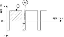
また、少なくとも一方の前記被接合物が半導体であり、各被接合物の接合面を+−両電界に切り替わる交番電源からなるプラズマで減圧下でドライ洗浄した後、洗浄された接合表面同士を常温接合する方法及び接合装置からなる。(請求項10、28)少なくとも一方の被接合物が半導体である場合などでは、+イオンや−電子が半導体の回路面に衝突すると、回路、特にゲート酸化膜などにチャージアップダメージを与えることになる。これを回避するために+イオンと−電子を交互に衝突させることにより電荷がチャージする前に中和させてしまうことができる。そうすることによりチャージアップダメージを回避することが可能となる。また、前記交番電源が1:5より均等に切り替わる方法及び接合装置からなる。交互に切り替わる比率としては1:5より均等であればチャージアップダメージを軽減できる。また、1:2より均等であればより好ましい。また、前記交番電源においてVdcが−値であり、+領域が20%〜40%である方法及び接合装置からなる。また、Arや酸素プラズマなどは+イオンとなるため、加速して洗浄面に衝突させエッチングするためには、被接合物を保持する電極は−電界である必要がある。そのため、Vdc値は−であることが好ましい。また、前記Vdc値を調整できる交番電源からなるプラズマである方法及び接合装置からなる。+−を均等にしすぎると+イオンが衝突する機会が減るため洗浄能力が減少する。また、−電子によるチャージアップダメージが発生する。そのため、アプリケーション毎に最適なVdc値を調整できるようにすることにより、チャージアップダメージを起こさず最適な洗浄能力を発揮することができ、効果がある。また、前記交番電源がRFプラズマである方法及び接合装置からなる。交番電源として交流からなるRFプラズマを使用することで交互に電界を+−切り替えることが容易にできる。また、前記Vdc値の調整で容易に+と−の割合を調整可能である。また、前記交番電源がパルス波からなるプラズマである方法及び接合装置からなる。交番電源としてパルス波を用いることができる。パルス波であれば急峻な立ち上がりと立ち下げが可能であり、洗浄能力もアップする。また、前記パルス波が+領域時間と−領域時間を調整可能な交番電源からなるプラズマである方法及び接合装置からなる。また、Vdc値の調整だけでなく、パルス幅や間隔を調整することで+−の割合や衝突時間を管理できるので交流であるRFよりより細かく設定が可能となり、最適な値を探し出しやすい。図4にRFプラズマ電源図を図5にパルス波プラズマ電源図を示す。
In addition, at least one of the objects to be bonded is a semiconductor, and the bonded surfaces of the bonded objects are dry-cleaned under reduced pressure with plasma composed of an alternating power source that switches between both electric fields. It consists of a joining method and a joining device. (
また、前記接合時に180℃以内に加熱する方法及び接合装置からなる。(請求項11、29)接合時に加熱を併用することで接合マージンがアップする。また、従来常温では接合できなかったものも接合可能となる。特に活性化時間の短いものは再付着も早く、加熱併用することで接合界面での粒界拡散がし易くなり接合し易くなる。ホーン側においてもノーダルポイントにヒータを設けたり外部加熱手段をホーンへ熱伝導させることで加熱併用が可能である。従来の低温接合は鉛錫ハンダが183℃であるのでそれ以下の温度で接合できることは有効である。また、150℃以下、100℃以下での接合も可能で好ましい。また、室温であればさらに良い。特に金であれば低温で接合し易く好ましい。
Further, it comprises a method of heating within 180 ° C. during the joining and a joining device. (
また、前記超音波振動が縦振動である方法及び接合装置からなる。(請求項12、30)また、前記超音波振動ヘッドが縦振動タイプであり、振動子がホーンの上部に位置する構造である方法及び接合装置からなる。ウエハーのような大面積を面接合させるために超音波振動を印加する方法として、横振動も考えられるが面でコスリあわせることはかなりのエネルギーが必要となる。今回接合は表面活性化力により行うため、超音波は加重低下やパーティクルの粉砕、埋没にさえ貢献できればいい。しかし、横振動では同時に接合された面部分も含めて振動させることは不可能である。そのため縦振動を使用すれば接合はできなくとも小さなエネルギーで他の面部分がたとえ接合されていても、加重低下やパーティクルの粉砕、埋没には効果があり、有効である。また、従来ダメージを軽減するために横振動を使用していたが、接合均一性や位置ずれの問題から縦振動が有効であることが分かる。しかし、縦振動では、ダメージが起こるため、いかにダメージを軽減して縦振動で接合するかがポイントとなる。その解決策として、振幅を1μm以下とすることにある。そうすることにより被接合物の弾性変形で衝撃を吸収することができる。例えば20μm高さの金バンプのついた半導体チップであればバンプの弾性変形で1μmの振幅を吸収することができる。また、振動伝達ホーンの先端に弾性材を取り付けることにより、縦振動による衝撃を吸収することができる。縦振動の衝撃が問題となるのは、振動伝達ホーンとチップの間に隙間ができながら衝撃的にチップを上から金槌で叩くような動作となってしまうからである。そのため、隙間が開かないように弾性材やバンプで吸収してやればダメージは軽減できる。接合においては、接合界面には応力変化は伝わるので界面での粒子のつぶれや移動により新生面があらわれ接合は進むので問題は無い。これらの縦振動を使用した超音波接合装置におけるヘッド構造としては、図1に示す50%以上縦振動を含む効率的な、振動子、振動伝達ホーン、被接合物が縦に配列された状態で接合する方法からなる。特に表面活性化した後の超音波接合であれば横振動によるすべりで接合界面の酸化膜などを破る必要は無いので、縦振動を与えて接合界面の応力を増加させてやれば、接合加重を落として接合させることが可能である。また、縦振動ヘッド構造とすることで、ホーンをセラミック材にして静電チャックを盛り込むことも可能となり、上部を振動子に密着させることができるので下部のみにプラズマを集中して発生でき、好ましい構造となる。また、横振動させるには接合面積が大きくては不可能であるが、縦振動においては大面積な面接合、例えばウエハー接合にも適用できる。また、横振動では接合面周辺に応力集中するが縦振動では均一な応力が発生し、大面積において均一な接合が可能となり適する。
The ultrasonic vibration is a longitudinal vibration and a joining apparatus. (
また、両被接合物を対向保持する保持ツールのうち、少なくとも一方の保持ツールの被接合物と対向面に複数のピエゾアクチュエータが接触または連結された接合機構において、両被接合物を接触加圧した状態で、ピエゾアクチュエータの伸縮動作にて縦振動を印加し接合する方法からなる。(請求項13)対向する2つの被加圧物を保持する2つの保持ツールと、少なくとも一方の保持ツールを加圧軸方向へ移動および加圧する昇降軸と、複数のピエゾアクチュエータと、複数のピエゾアクチュエータを振動制御する振動印加手段を備え、両被加圧物を対向保持する保持ツールのうち、少なくとも一方の保持ツールの被加圧物と対向面に複数のピエゾアクチュエータが接触または連結された接合機構において、両被加圧物を接触加圧した状態で、ピエゾアクチュエータの伸縮動作にて縦振動を印加する接合装置からなる。(請求項31)ピエゾ素子とは、電圧印加により伸縮する圧電素子を示し、圧電素子に含む。また、圧電素子の材質は問わない。被接合物同士を接合する方法において、従来から超音波振動を印加して接合する方法が知られている。ここでいう振動とは低周波から超音波領域を含むものを示し、本発明に含む。また、接合には良く超音波が利用され好ましい。また、保持ツールと共振させることで大きなエネルギーを出力させることができ好ましい。また、加熱接合する場合や表面活性化による接合の場合においても、振動を印加することで接合界面の応力が増すことから接合荷重は約半分の荷重で接合が行われる。これは、接合するには微小な界面の凹凸が押しつぶされて密着する必要があることから、振動による応力増加が寄与するためである。また、被接合物としてウエハーのような大面積なものの場合には、大面積で高荷重のもと振動を与えられる方式である、少なくとも一方の保持ツールの被接合物と対向面に複数のピエゾアクチュエータが接触または連結された接合機構において、両被接合物を接触加圧した状態で、ピエゾアクチュエータの伸縮動作にて縦振動を印加し接合する前記方法が有効である。また、ピエゾアクチュエータの配置数が3であり、円周上に等間隔で配置されている項16に記載の方法からなる。また、ピエゾアクチュエータの配置数が3であり、円周上に等間隔で配置されている前記に記載の接合装置からなる。振動子となるピエゾアクチュエータの配置位置としては、例えば被接合物であるウエハーの中心から円周上に等間隔で配置されることが荷重を均等に受け、かつ、振動を均等に与え、共振させやすいことから好ましい。最少数としては面で傾かないように受けるには3となる。また、3次元的な動作をさせる上でも3が好ましい。円周上に3箇所配置することが最少数であり、効率的で安定する。
Further, of the holding tools that hold both objects to be opposed to each other, in a bonding mechanism in which a plurality of piezo actuators are in contact with or connected to the object to be bonded of at least one holding tool, both the objects to be bonded are contact-pressed. In this state, a longitudinal vibration is applied by the expansion / contraction operation of the piezo actuator to join. (13) Two holding tools for holding two opposed objects to be pressed, a lifting shaft for moving and pressing at least one holding tool in the direction of the pressing axis, a plurality of piezo actuators, and a plurality of piezos A joint comprising a plurality of piezo actuators in contact with or connected to the object to be pressed of at least one holding tool among the holding tools that hold both of the objects to be pressed facing each other with vibration applying means for controlling the vibration of the actuator. The mechanism is composed of a joining device that applies longitudinal vibration by an expansion / contraction operation of a piezo actuator in a state in which both objects to be pressed are in contact with pressure. (Claim 31) A piezo element refers to a piezoelectric element that expands and contracts when a voltage is applied, and is included in the piezoelectric element. Moreover, the material of a piezoelectric element is not ask | required. As a method for joining objects to be joined, a method for joining by applying ultrasonic vibration has been known. The term “vibration” as used herein refers to a vibration that includes an ultrasonic region from a low frequency, and is included in the present invention. Also, ultrasonic waves are often used for bonding, which is preferable. Further, it is preferable that a large energy can be output by resonating with the holding tool. In addition, in the case of bonding by heating or in the case of bonding by surface activation, since the stress at the bonding interface is increased by applying vibration, bonding is performed with a bonding load of approximately half. This is because an increase in stress due to vibration contributes to the fact that the unevenness at the minute interface needs to be crushed and brought into close contact for bonding. In addition, in the case where the object to be bonded is a large area such as a wafer, a plurality of piezoelectric elements are provided on a surface opposite to the object to be bonded of at least one holding tool. In the joining mechanism in which the actuator is contacted or coupled, the above-described method is effective in which longitudinal vibration is applied and joined by the expansion / contraction operation of the piezo actuator in a state where both the objects to be joined are contacted and pressurized. The number of piezoelectric actuators is 3, and the method according to
また、前記両被接合物を接触加圧した状態で、複数のピエゾアクチュエータ間の振動位相を制御し、回転方向に順次波がながれるように伸縮動作させ接合する方法からなる。(請求項14)複数のピエゾアクチュエータ間の振動位相を制御する手段を備え、前記両被接合物を接触加圧した状態で、複数のピエゾアクチュエータ間の振動位相を制御し、回転方向に順次波がながれるように伸縮動作させ接合する接合装置からなる。(請求項32)並列に配置されたピエゾアクチュエータの振動位相を制御してやることで3次元的な動作が可能となる。特に円周上等間隔に3箇所に配置されている場合は、振動印加手段によって例えばサインカーブからなる伸縮電圧を印加し、位相を120°ずつずらしてやれば回転方向に順次波がながれるが如く3次元的な振動動作をさせることができる。前述のように単純に縦振動だけよりもウェーブのような波がながれるが如く動作を加えた方が、接合時に噛み込んだ空気や真空においても発生する界面の隙間から生じるボイドを抜くことが順次押し出すことで可能となる。また、接合においても集中荷重が順次流れていくので前述原理からなる微小凹凸を密着させる接合にも有効である。特に全面が均等に加圧するのと比べ、ある部分に集中荷重がかかりながら移動していくことで、少ない荷重で接合し易い。ここでいう振動とはこのような3次元的な連続動作も含む。 In addition, in a state in which both the objects to be bonded are in contact and pressure, the vibration phase between the plurality of piezoelectric actuators is controlled, and the bonding is performed by expanding and contracting so that the wave is sequentially generated in the rotation direction. (14) A means for controlling a vibration phase between a plurality of piezo actuators is provided, and the vibration phase between the plurality of piezo actuators is controlled in a state in which both the objects to be bonded are in contact with pressure, and a wave is sequentially generated in the rotation direction. It consists of a joining device that is stretched and joined so as to flow. (Claim 32) By controlling the vibration phase of the piezo actuators arranged in parallel, a three-dimensional operation becomes possible. In particular, in the case where they are arranged at three equal intervals on the circumference, if an expansion / contraction voltage composed of, for example, a sine curve is applied by the vibration applying means and the phase is shifted by 120 °, a wave is sequentially generated in the rotational direction. A dimensional vibration operation can be performed. As described above, it is possible to remove voids generated from gaps in the interface that are generated even in the air and vacuum that are bitten at the time of operation when the operation is performed so that a wave like a wave is generated rather than simply longitudinal vibration. This can be done by extruding. In addition, since concentrated load sequentially flows in the joining, it is also effective for joining the minute irregularities based on the above principle. In particular, as compared with the case where the entire surface is evenly pressurized, it is easy to join with a small load by moving while applying a concentrated load to a certain portion. The vibration here includes such a three-dimensional continuous operation.
また、前記超音波振動を印加して接合する接合過程において加圧力及び/又は超音波振動エネルギーを上昇するカーブで増大させる方法からなる。(請求項15、33)また、接合面積の増大に比例して、加圧力及び/又は超音波振動エネルギーを増大させる方法が好ましい。今、接合の課程をミクロに考えると、接合面には小さな凹凸や複数の接合部での高さの違いから接合が進む課程で接合面積は順次大きくなっていくと考えられる。よって接合課程において接合面積に比例した加圧力と超音波振動エネルギーを加えることが必要となる。これが、接合初期において、接合面積以上の超音波振動エネルギーが加えられると接合部や基材に余分なエネルギーが加えられることによる破壊やダメージが発生する。また、超音波振動の伝達を考えた時、共振器から第1の被接合物、第2の被接合物、ステージと順次振動が伝達されていくが、一定の振動が与えられた状況で加圧力を増加させると各伝達界面における摩擦力が増すため、振動は下層へ移っていくことは容易に理解できる。そのため初期から大きな加圧力を加えると第1、第2の被接合物間で接合のための目的のすべりが生じず第2の被接合物の基材が柔らかいと超音波振動エネルギーを吸収してしまい、接合ができなくなる。このようなことから、接合課程において、加圧力及び/又は超音波エネルギーを増大させて接合することが有効であり、これらを制御する方法としては上昇するカーブで増大させることが有効である。また、接合面積の増大に比例させて増大させてやることが好ましい。補足すると、初期に低い加圧力で超音波振動を与えるとある面積の接合が始まる。そうすると第1の被接合物は第2の被接合物と一定の力で結合されるため第1、第2の被接合物間での振幅が小さくなり、共振器と第1の被接合物間ですべりが大きくなる。そこで加圧力を増加すると共振器と第1の被接合物間の摩擦力増加にともないすべりが押さえられ、第1の被接合物に超音波振動エネルギーが伝達されより接合面積が大きくなっていく。また、その時々の最適な超音波振動エネルギーを加圧力制御により接合箇所に集中して印加するので、余分なダメージを与えず良好な接合が行える。接合面積が増加すると第1、第2の被接合物間の結合力が増し、振幅が小さくなることを利用し、接合面積の増大は次の方法で読み取ることができる。第1、第2の被接合物の振幅を検出する振幅検出手段を有し、前記接合面積の増大を第1、第2の被接合物間の振幅を測定することにより読み取る方法からなる。また、実際の接合界面の振幅でなくとも不安定要素がなければ、次の順で推定することができる。被接合物の振幅検出手段を有し、前記接合面積の増大を第1の被接合物の振幅を測定することにより読み取る方法からなる。また、共振器の振幅検出手段を有し、前記接合面積の増大を共振器の振幅を測定することにより読み取る方法からなる。また、振動子の振幅は振動子のピエゾ素子にかかる出力電流に対する戻り電流値から推測することができるので、前記接合面積の増大を振動子の出力電流に対する戻り電流値により読み取る方法からなる。実際に接合される界面での振幅を常に接合に最適な値とする方法として、第1、第2の被接合物の振幅を検出する複数の振幅検出手段を有し、第1、第2の被接合物間の振幅が任意の一定値となるように加圧力及び/又は超音波振動エネルギーを制御する方法からなる。また、被接合物の振幅検出手段を有し、第1の被接合物の振幅が任意の一定値となるように加圧力及び/又は超音波振動エネルギーを制御する方法からなる。これは前述のように接合面積が増加すると振幅が小さくなるため、第1、第2の被接合物間での振幅が一定になるように加圧力及び/又は超音波振動エネルギーを増加してやれば常に接合界面において一定の振幅が得られるため、良好な接合が進む。また、第2の被接合物はステージに保持されている状況に変化が無いとすれば、第1の被接合物の振幅を読み取るだけでも同様な結果が得られる。但し、共振器や振動子の振幅は共振器と第1の被接合物間でのすべりに影響されるため、一定とはならないので採用は好ましくない。ダメージ無く、かつ、接合が全て良好に完了し、かつ超音波エネルギーを印加しすぎによるダメージを無くすためには、前期加圧力及び/又は超音波振動エネルギーがある目的値に達した時に超音波振動を停止する方法からなる。目的とされる接合面積を接合するために必要な加圧力と超音波振動エネルギーはあらかじめ決められているので、その目的値に達した時に超音波振動を停止すればいい。従来、上下駆動制御部と荷重制御機構部に分けられ、加圧力はエアシリンダによるエア圧力によりコントロールされているため、応答性が遅く、エアシリンダのシュウドウ抵抗から上下動速度はエアシリンダのスピードに制限されてしまい、高速で動作ができなかったが、接合機構が接合作業の上下駆動機構に上下駆動モータと加圧力検出手段を持ち、加圧力制御が上下駆動モータのトルクで制御する方式である方法からなる。本方式を採用することにより、応答性の早い加圧動作と高速上下動作が可能になる。
Further, the method includes a method of increasing the applied pressure and / or ultrasonic vibration energy with a curve that increases in the joining process of applying the ultrasonic vibration. (
また、振幅検出手段を有し、前記超音波振動を印加して接合する接合過程において、振動物の振幅を測定し、目的値となるように超音波振動エネルギーを制御する方法及び接合装置からなる。(請求項16、34)実際に接合される第1、第2被接合物間の振幅をある任意な目的値とすることが大事であり、次に測定する振動物の好ましい順に記述する。まず、前記振動物が第1、第2の被接合物であり、第1、第2の被接合物間の振幅を測定し、目的値となるように超音波振動エネルギーを制御する方法からなる。また、第2の被接合物がステージに安定吸着保持されているとすると、第2の被接合物の振幅を測定しなくとも、測定する振動物として第1の被接合物の振幅を測定することにより達成できる。また、第1の被接合物と共振器間の摩擦が安定し、振動伝達が安定しているとすると、測定する振動物として共振器の振幅を測定することにより達成できる。また、過剰振動によるダメージの発生する不良品を無くすためには、測定された振幅がある任意の最大振幅値以上になった場合に超音波振動を停止する方法からなる。また、振動が小さ過ぎるための接合不良品を無くすためには、測定された振幅がある任意の最小振幅値以上にならない場合に超音波振動を停止する方法からなる。また、これら前記振幅検出手段を認識手段移動テーブル上に設けることにより、被接合物の品種による大きさの違いがあっても容易に測定場所へ移動することが可能であり、また、1つの検出手段で複数の場所の測定を行うこともできる。また、前記振幅検出手段がうず電流式または静電容量式または光照射式または音波式検出手段を使用することにより、2桁安価な検出手段を採用でき、小型であるため、複雑な入り組んだ場所でも測定が可能となる。従来は、レーザードップラー測定器を使用し、数十kHzで振動しているものを実際にその分解能でその速度で振動物の動きをとらえていたため、非常に高価なものが必要であった。しかし、今回の目的は、振幅の目的値になっているかどうか、その差が分かれば良く、実際の振幅が何μmで何Hzであるかを知る必要は無い。そのため、高速応答性が無い従来のうず電流式または静電容量式または光照射式または音波式検出手段を使用し、高速で振動しているものの平均的な差が検出できれば目的は達成できる。本方式が特に適する場合は、被接合物が少なくとも一方の被接合物に金属突起を施し、少なくとも一方の被接合物が半導体チップである方法からなる。半導体の電極となる金属突起部の下層金属部は超音波振動によりマイクロクラックが入りダメージを帯びやすい。そのため、本方式は特に適する。上記のような本発明に係る接合方法及び装置においては、被接合物同士を超音波接合する接合課程において、振幅検出手段を有し、振動物の振幅を測定し、目的値となるように超音波振動エネルギーを制御するため、微妙な加圧力と接合課程のずれや、ゴミ、被接合物表面状態による摩擦係数のバラツキなどの外乱が加わっても安定した目的振幅を得ることができ、安定した超音波接合が達成できる。また、実際に接合される第1、第2被接合物間の振幅を振幅検出手段により測定してある任意な目的値とすることができるので、確実な接合状態を得ることができる。また、異常振動をキャッチすることにより不良品を作らないようにできる。また、振幅検出手段として安価でコンパクトなものが採用できる。
In addition, the method includes a method and a bonding apparatus that have amplitude detection means, measure the amplitude of a vibrating object, and control ultrasonic vibration energy so as to obtain a target value in a bonding process in which the ultrasonic vibration is applied and bonded. . (
また、前記被接合物が複数の微少バンプを備えた半導体ウエハーまたはチップからなる方法及び接合装置からなる。(請求項17、18、35)また、前記方法で作られた被接合物が複数の微少バンプを備えた半導体ウエハーまたはチップからなる半導体装置からなる。被接合物が電極となるバンプを設けた半導体ウエハーやチップであると、接合部は多数の突起部分となるため、一気に全面積を接合する面接合に比べ、個々の突起バンプにおいて順次超音波接合を進めることができるので超音波接合に適する。
Further, the object to be bonded includes a method and a bonding apparatus including a semiconductor wafer or a chip provided with a plurality of minute bumps. (
お互いに密着し合う面形状をした複数の被接合物の接合表面をエネルギー波により表面活性化した後、固層で接合する方法であって、減圧下の真空チャンバー内で対向配置された被接合物同士を接触加圧し、超音波振動を印加することにより、300Mpa以下の加圧力で接合でき、接合面にパーティクルが存在するウエハーなどの被接合物においてもパーティクルを粉砕及び/又は埋没させ、ボイドレスで接合させることができる。 A method in which the surfaces of a plurality of objects to be bonded in close contact with each other are activated by energy waves and then bonded in a solid layer, which are bonded in a vacuum chamber under reduced pressure. By contacting and pressing objects and applying ultrasonic vibration, bonding can be performed with a pressure of 300 MPa or less, and particles can be crushed and / or buried even in bonded objects such as wafers where particles exist on the bonding surface. Can be joined.
また、接合表面が大気中で酸化するものでもプラズマ洗浄後、真空維持した状態で超音波を印加することで接合することができる。これは従来低温では接合が難しかった、AlやSi、セラミック、SIO2、ガラス、酸化物などの接合が可能となる。また、従来の表面活性化接合に比べ接合荷重を半分以下に押さえることが可能となり、従来実質接合が難しかった固い金属においても接合が可能となる。また、縦振動を利用することでウエハーのような大面積の接合も可能となる。 Moreover, even if the bonding surfaces are oxidized in the atmosphere, bonding can be performed by applying ultrasonic waves in a vacuum maintained state after plasma cleaning. This makes it possible to join Al, Si, ceramic, SIO2, glass, oxide, etc., which were difficult to join at low temperatures. In addition, the bonding load can be reduced to half or less compared to the conventional surface activated bonding, and even a hard metal that has been difficult to be substantially bonded can be bonded. Further, by using the longitudinal vibration, it is possible to bond a large area like a wafer.
以下に本発明の望ましい実施形態について、図面を参照して説明する。 Hereinafter, preferred embodiments of the present invention will be described with reference to the drawings.
(第1実施形態)
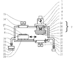
図1に本発明の一実施形態に係る真空中での超音波接合装置を示す。この実施形態では第1の被接合物である上ウエハーと第2の被接合物である下ウエハーを接合するための装置として例に上げる。
(First embodiment)
FIG. 1 shows an ultrasonic bonding apparatus in a vacuum according to an embodiment of the present invention. In this embodiment, the apparatus is exemplified as an apparatus for bonding an upper wafer as a first object to be bonded and a lower wafer as a second object to be bonded.
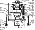
まず、装置構成について記述する。上ウエハーを保持するヘッド7と下ウエハーを保持するステージ8が真空チャンバー11中に配置され、ヘッドはトルク制御式昇降駆動モータ1が連結されたZ軸昇降機構2とZ軸昇降機構2を回転させるθ軸機構と、ヘッド部をXY水平方向へアライメント移動させるXYアライメントテーブル6により、X、Y、θ方向のアライメント移動手段とZ方向の昇降手段からなる。圧力検出手段4により検出された接合時の加圧力をトルク制御式昇降駆動モータ1にフィ−ドバックすることで位置制御と圧力制御が切り替えながら行えるようになっている。また、圧力検出手段4は被接合物同士の接触検出にも利用できる。XYアライメントテーブル6は真空中でも使用できる手段を使用するが、Z、θ軸機構は減圧チャンバー外部に設置するため、Oリング5により移動可能にヘッド部と外部を遮断されている。ヘッド及びステージの転写型と基材の保持手段としては、メカニカルなチャッキング方式であっても良いが、静電チャックを設けることが好ましい。また、加熱のためのヒータを備え、保持手段、加熱手段の2つの機能を備える。ヘッド及びステージの被接合物保持手段としては、メカニカルなチャッキング方式であっても良いが、静電チャックを設けることが好ましい。また、加熱のためのヒータを備え、プラズマ電極ともなっており、保持手段、加熱手段、プラズマ発生手段の3つの機能を備える。
First, the apparatus configuration will be described. A head 7 for holding an upper wafer and a
ヘッド部は接合時に超音波振動を併用するため、ヘッド7はホーン保持部24、ホーン25、振動子26から構成され、振動子による振動がホーンに伝達され、超音波振動をホーンが保持する被接合物へ伝達する。ホーン保持部はホーンや振動子の振動を殺さないように保持する手段からなる。この時の伝達率はホーンと被接合物の摩擦係数と圧力で決まるため、接合が進むにつれ接合面積に比例して加圧力を制御してやることが好ましい。また、ウエハーのような大面積を接合する場合は、横振動タイプの超音波ヘッドでは横振動させるには接合面積が大きくては不可能であるが、縦振動タイプの超音波ヘッドであれば、大面積な面接合も可能となる。
Since the head unit also uses ultrasonic vibration at the time of joining, the head 7 is composed of a
減圧手段としては、排気管15に真空ポンプ17がつながれ、排気弁16により開閉と流量調整が行われ、真空度を調整可能な構造となっている。また、吸入側は、吸気管18に吸入ガス切り替え弁20が連結され吸気弁19により開閉と流量調整が行われる。吸入ガスとしてはプラズマの反応ガスを2種類連結でき、例えばArと酸素をつなぐことができる。もう一つは大気解放用の大気または窒素がつながれる。真空度や反応ガス濃度は吸気弁19と排気弁16の開閉含めた流量調整により最適な値に調整可能となっている。また、真空圧力センサーを真空チャンバー内に設置することで自動フィードバックすることもできる。
As the decompression means, a
アライメント用の光学系からなるアライメントマーク認識手段がステージ待機位置の上方とヘッド下方に真空チャンバー外部に配置される。認識手段の数は最低ステージ、ヘッド側に1つずつあれば良く、チップのような小さなものを認識するのであれば、アライメントマークがθ方向成分も読みとれる形状や2つのマークを1視野内に配置することで1つの認識手段でも十分読み取ることができるが、本実施例のようにウエハーのような半径方向に大きなものは両端に2つずつ配置した方がθ方向の精度を高く読み取ることができるので好ましい。また、認識手段は水平方向や焦点方向へ移動可能な手段を設けて、任意の位置のアライメントマークを読みとれるようにしても良い。また、認識手段は、例えば可視光やIR(赤外)光からなる光学レンズをともなったカメラからなる。真空チャンバーには認識手段の光学系が透過できる材質、例えばガラスからなる窓が配置され、そこを透過して真空チャンバー中の被接合物のアライメントマークを認識する。被接合物上には例えば各上ウエハー、下ウエハーの対向する表面にアライメントマークが施され位置精度良く認識することができる。アライメントマークは特定の形状であることが好ましいが、ウエハー上に施された回路パターンなどの一部を流用しても良い。また、マークとなるものが無い場合はオリフラなどの外形を利用することもできる。ステージ待機位置で上下ウエハー上の両アライメントマークを読み取り、接合位置へステージを移動させ、ヘッド側でX、Y、θ方向へアライメント移動を行う。待機位置の読みとり結果を接合位置で反映させるため、ステージの待機位置と接合位置の相対移動距離ベクトルは繰り返し同じ結果となるよう精度が必要である。そのため、ガイドには高精度な繰り返し精度を持つものを使用し、かつ、両サイドでの位置認識を高精度に読み取るリニアスケールを配置している。リニアスケールを移動手段にフィードバックすることで停止位置精度を高める方法と移動手段が簡易なシリンダのようなものやボルトナット機構のようなバックラッシュのあるものである場合は、リニアスケールを両停止位置で読み取り、行き過ぎや行き足りない分をヘッド側アライメント移動手段を移動させる時に考慮して補正することで容易に高精度を達成することができる。また、ナノレベルにより高精度にファインアライメントする場合は、粗位置決めを行った後、上ウエハーと下ウエハーを数μm程度に近接させた状態でヘッド側認識手段に可視光、IR(赤外)兼用認識手段を使用し、ステージのアライメントマーク位置には透過孔や透過材を設けることで、下部からステージを透過して両ウエハー上のアライメントマークを赤外透過して同時認識し、再度X、Y、θ方向へアライメントすることができる。認識手段が焦点方向に移動手段を持つ場合は上下個別に認識することもできるが、近接させて同時認識した方が精度上より好ましい。ファインアライメントする場合、繰り返してアライメントすることで精度向上が可能となり、また、θ方向は芯ぶれの影響が出るので一定以内に入った後はXY方向のみのアライメントを行うことでナノレベルまで精度を向上できる。画像認識手段としてはサブピクセルアルゴリズムを使用することで赤外線の解像度以上の認識精度を得ることが可能となる。また、近接させてアライメントしておけば接合時に必要なZ移動量は最低限の数μm以内となるため、Z移動に対するガタや傾きを最小限に押さえられ高精度なナノレベルの接合精度を達成することができる。 Alignment mark recognition means comprising an alignment optical system is disposed outside the vacuum chamber above the stage standby position and below the head. The number of recognition means should be at least one on the stage and head side. If a small object such as a chip is to be recognized, the shape of the alignment mark can also read the θ direction component and two marks within one field of view. Although it is possible to read sufficiently even with one recognition means by arranging, it is possible to read with high accuracy in the θ direction when two large ones in the radial direction such as a wafer are arranged at both ends as in this embodiment. It is preferable because it is possible. Further, the recognition means may be provided with means that can move in the horizontal direction or the focal direction so that the alignment mark at an arbitrary position can be read. The recognition means is a camera with an optical lens made of, for example, visible light or IR (infrared) light. A window made of a material, for example, glass, that can be transmitted through the optical system of the recognition means is disposed in the vacuum chamber, and the alignment mark of the object to be bonded in the vacuum chamber is recognized through the window. For example, alignment marks are provided on the surfaces of the upper wafer and the lower wafer facing each other on the object to be bonded so that they can be recognized with high positional accuracy. The alignment mark preferably has a specific shape, but a part of a circuit pattern or the like provided on the wafer may be used. Further, when there is no mark, an outline such as an orientation flat can be used. Both alignment marks on the upper and lower wafers are read at the stage standby position, the stage is moved to the bonding position, and the alignment is moved in the X, Y, and θ directions on the head side. In order to reflect the reading result of the standby position at the joining position, it is necessary to have an accuracy so that the relative movement distance vectors of the standby position of the stage and the joining position are repeatedly the same. For this reason, a guide having a high repeatability is used, and a linear scale that reads position recognition on both sides with high accuracy is arranged. If the linear scale is fed back to the moving means to improve the stopping position accuracy and the moving means is a simple cylinder or backlash like a bolt / nut mechanism, the linear scale should be Therefore, it is possible to easily achieve high accuracy by making corrections by taking into account when the head-side alignment moving means is moved. For fine alignment with high accuracy at the nano level, after rough positioning, the head side recognition means is used for both visible light and IR (infrared) with the upper wafer and lower wafer close to about a few μm. By using a recognition means and providing a transmission hole or transmission material at the position of the alignment mark on the stage, the alignment mark on both wafers is transmitted through the stage from the bottom and transmitted through the infrared rays, and is simultaneously recognized. , Θ direction can be aligned. When the recognition means has a movement means in the focal direction, it can be recognized separately in the upper and lower directions, but it is more preferable in terms of accuracy to make the recognition close and simultaneously recognize. When fine alignment is performed, accuracy can be improved by repetitive alignment. In addition, since the θ direction is affected by the runout, the accuracy is reduced to the nano level by performing alignment only in the XY direction after entering within a certain range. It can be improved. By using a sub-pixel algorithm as an image recognition means, it is possible to obtain recognition accuracy that is higher than the infrared resolution. In addition, if they are aligned close to each other, the amount of Z movement required during bonding is within a minimum of several μm, so that the backlash and inclination with respect to Z movement can be kept to a minimum, achieving highly accurate nano-level bonding accuracy. can do.
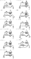
次に動作フローを図2を参照しながら解説する。まず、1に示すように、真空チャンバーの前扉を開いた状態で上ウエハーと下ウエハーをステージとヘッドに保持させる。これは人手でも良いが、カセットから自動でローディングしても良い。次に2に示すように、前扉を閉め、真空チャンバー内を減圧する。不純物を取り除くために10−3Torr以下に減圧することが好ましい。続いて3、4に示すように、プラズマ反応ガスである例えばArを供給し、例えば10−2Torr程度の一定の真空度でプラズマ電極にプラズマ電源を印加し、プラズマを発生させる。発生されたプラズマイオンは電源側に保持されたウエハーの表面に向かって衝突し、表面の酸化膜や有機物層などの付着物がエッチングされることにより表面活性化される。同時に両ウエハーを洗浄することも可能であるが、1つのマッチングボックスを切り替えることで交互に洗浄することもできる。また、洗浄後または洗浄中に反応ガスやエッチング物を取り除くために10−3Torr以下に減圧することが好ましい。接合表面に打ち込まれたArを取り除くには100〜200℃程度に加熱を併用することもできる。続いて5に示すようにステージ待機位置でヘッド側、ステージ側の各々の認識手段で真空中で上下ウエハー上のアライメントマークを読み取り、位置を認識する。続いて6に示すように、ステージは接合位置へスライド移動する。この時の認識された待機位置とスライド移動した接合位置の相対移動はリニアスケールを用いて高精度に行われる。ナノレベルの高精度が要求される場合は7に示す工程を追加する。粗位置決めを行った後、上ウエハーと下ウエハーを数μm程度に近接させた状態でヘッド側認識手段に可視光、IR(赤外)兼用認識手段を使用し、ステージのアライメントマーク位置には透過孔や透過材を設けることで、下部からステージを透過して両ウエハー上のアライメントマークを同時認識して再度X、Y、θ方向へアライメントすることができる。この場合、繰り返してアライメントすることで精度向上が可能となり、また、θ方向は芯ぶれの影響が出るので一定以内に入った後はXY方向のみのアライメントを行うことでナノレベルまで精度を向上できる。続いて8に示すように、ヘッドを下降させ、両ウエハーを接触させ、位置制御から圧力制御へと切り替え加圧する。圧力検出手段により接触を検出し高さ位置を認識しておいた状態で、圧力検出手段の値をトルク制御式昇降駆動モータにフィードバックし設定圧力になるように圧力コントロールする。初期加圧が加えられた状態で超音波振動を印加し、接合界面での応力が増加することにより低荷重で接合が進む。加圧力は接合面積の増加に伴い比例して増加させてやることが好ましい。また、ウエハーのようにお互いに密着し合う面形状をした被接合物の接合表面には小さなゴミとなるパーティクルが存在し、低温で固層のまま接合するとパーティクル周辺に隙間ができ、大きくボイドとなって接合されない。これを除去するには接合時に超音波を印加することで、パーティクル部に応力が集中するため砕けるか、基材内に埋没させることができる。超音波では面同士は接合できないが、接合力は表面活性化によって接合されるので超音波は、パーティクルを粉砕及び/又は埋没させるために使用する。真空中であるのでパーティクルさえ無くなれば隙間なく接合することができる。また、必要に応じて接合時に加熱を加える。また、残留応力を除去したり接合強度をアップするために超音波接合後、加熱する場合は、常温で接触させた後、昇温させることで精度をキープさせた状態で加熱することもできる。続いて9に示すように、ヘッド側保持手段を解放し、ヘッドを上昇させる。続いて10に示すように、ステージを待機位置に戻し、真空チャンバー内を大気解放する。続いて11に示すように、前扉を開けて接合された上下ウエハーを取り出す。人手でも良いが自動でカセットにアンローディングすることが好ましい。 Next, the operation flow will be described with reference to FIG. First, as shown in FIG. 1, the upper wafer and the lower wafer are held on the stage and the head while the front door of the vacuum chamber is opened. This may be done manually, but may be automatically loaded from the cassette. Next, as shown in 2, the front door is closed and the vacuum chamber is depressurized. In order to remove impurities, the pressure is preferably reduced to 10 −3 Torr or less. Subsequently, as shown in 3 and 4, for example, Ar, which is a plasma reaction gas, is supplied, and a plasma power source is applied to the plasma electrode at a certain degree of vacuum, for example, about 10 −2 Torr to generate plasma. The generated plasma ions collide toward the surface of the wafer held on the power source side, and surface deposits such as an oxide film and an organic layer are etched to activate the surface. Both wafers can be cleaned at the same time, but can also be cleaned alternately by switching one matching box. Further, it is preferable to reduce the pressure to 10 −3 Torr or less in order to remove the reaction gas and the etched product after or during the cleaning. In order to remove Ar implanted into the bonding surface, heating can be used in combination at about 100 to 200 ° C. Subsequently, as shown in 5, the alignment marks on the upper and lower wafers are read in vacuum by the recognition means on the head side and the stage side at the stage standby position to recognize the positions. Subsequently, as shown in 6, the stage slides to the joining position. The relative movement between the recognized standby position and the sliding joint position at this time is performed with high accuracy using a linear scale. When nano-level high accuracy is required, the process shown in 7 is added. After rough positioning, visible light and IR (infrared) recognition means are used as the head side recognition means with the upper wafer and the lower wafer brought close to each other by several μm. By providing a hole and a transmission material, the alignment marks on both wafers can be simultaneously recognized through the stage from below, and alignment in the X, Y, and θ directions can be performed again. In this case, it is possible to improve accuracy by repeatedly aligning, and the θ direction is affected by the runout, so after entering within a certain range, the accuracy can be improved to the nano level by performing alignment only in the XY direction. . Subsequently, as shown in FIG. 8, the head is lowered, both the wafers are brought into contact with each other, and pressure is switched from position control to pressure control. In a state where the contact is detected by the pressure detection means and the height position is recognized, the value of the pressure detection means is fed back to the torque control type lifting drive motor to control the pressure so as to become the set pressure. Ultrasonic vibration is applied in a state where initial pressurization is applied, and the joining proceeds at a low load by increasing the stress at the joining interface. It is preferable to increase the applied pressure in proportion to the increase in the bonding area. In addition, there are particles that become small dust on the bonding surface of objects to be bonded that are in close contact with each other like a wafer, and when bonded as a solid layer at low temperature, gaps are created around the particles, and large voids and Will not be joined. In order to remove this, an ultrasonic wave is applied at the time of joining, so that stress concentrates on the particle part, so that it can be crushed or buried in the base material. The surfaces cannot be bonded with ultrasonic waves, but since the bonding force is bonded by surface activation, ultrasonic waves are used to pulverize and / or bury particles. Since it is in a vacuum, it can be joined without a gap if there are no particles. Further, heating is applied at the time of joining as necessary. In addition, when heating is performed after ultrasonic bonding in order to remove residual stress or increase bonding strength, heating can be performed in a state in which accuracy is maintained by increasing the temperature after contacting at normal temperature. Subsequently, as shown in 9, the head side holding means is released and the head is raised. Subsequently, as shown at 10, the stage is returned to the standby position, and the inside of the vacuum chamber is released to the atmosphere. Subsequently, as shown at 11, the front and rear wafers are taken out by opening the front door. Although it may be manual, it is preferable to automatically unload the cassette.
前記実施例では被接合物としてウエハーを上げたが、チップと基板であっても良い。ウエハーのような大きな接合面積である場合は、超音波振動ヘッド構造も縦振動タイプが良いが、チップのような接合面積の小さなものであれば図3に示すような横振動タイプのものがチップへの機械的ダメージも少ないので好ましい場合がある。被接合物はウエハーやチップ、基板に限らずいかなる形態のものでも良い。 In the above embodiment, the wafer is raised as the object to be bonded, but it may be a chip and a substrate. In the case of a large bonding area such as a wafer, the ultrasonic vibration head structure is preferably a longitudinal vibration type. However, if the bonding area is small such as a chip, a lateral vibration type as shown in FIG. This is preferable because there is little mechanical damage to the surface. The object to be bonded is not limited to a wafer, a chip, and a substrate, and may be in any form.
超音波振動ヘッドをヘッドとは別にステージ待機位置とヘッド位置の中間に配置し、アライメントして上部被接合物と下部被接合物をヘッドで装着した後、ステージを移動させ、超音波振動ヘッドにより上部より加圧、超音波振動を印加して接合しても良い。そうすることでホーンで被接合物を保持する手段やプラズマ電極機能が不要となり、ホーンの設計が容易になる。 Separately from the head, the ultrasonic vibration head is placed between the stage standby position and the head position, aligned, and after the upper and lower objects are mounted on the head, the stage is moved, and the ultrasonic vibration head Bonding may be performed by applying pressure and ultrasonic vibration from above. By doing so, the means for holding the object to be joined by the horn and the plasma electrode function become unnecessary, and the design of the horn becomes easy.
被接合物の保持手段としては静電チャック方式が望ましいが、メカニカルにチャッキングする方式でも良い。また、大気中でまず真空吸着保持させておいて密着させた後、メカニカルチャックする方法が密着性が上がり好ましい。 The holding means for the object to be joined is preferably an electrostatic chuck method, but may be a mechanical chucking method. In addition, a method of mechanically chucking after first vacuum-sucking and adhering in the atmosphere is preferable because adhesion is improved.
実施例ではヘッド側がアライメント移動手段と昇降軸を持ち、ステージ側がスライド軸を持ったが、アライメント移動手段、昇降軸、スライド軸はヘッド側、ステージ側にどのように組み合わせられても良く、また、重複しても良い。また、ヘッド及びステージを上下に配置しなくとも左右配置や斜めなど特に配置方向に依存しない。 In the embodiment, the head side has an alignment moving means and a lifting shaft, and the stage side has a slide shaft. However, the alignment moving means, the lifting shaft, and the slide shaft may be combined in any way on the head side and the stage side. It may be duplicated. Further, even if the head and the stage are not arranged vertically, it does not depend on the arrangement direction, such as left and right arrangement or diagonal.
ステージをスライドさせた状態でプラズマ洗浄する場合は、ヘッドとステージの電極形状、周囲の形状が似かよっているため電界環境は似かよっている。そのため、プラズマ電源を自動調整するマッチングボックスは個別のものを使用しなくとも、一つのもので電極を切り替え、順次ヘッド側、ステージ側と洗浄することができる。そうすることでコンパクト、コストダウンを達成できる。 When plasma cleaning is performed while the stage is slid, the electric field environment is similar because the electrode shape of the head and the stage and the surrounding shape are similar. Therefore, the matching box for automatically adjusting the plasma power source can be switched to the head side and the stage side sequentially by switching the electrodes by one without using an individual one. By doing so, compactness and cost reduction can be achieved.
超音波振動と呼ぶが振動周波数は特に超音波の領域でなくとも良い。特に縦振動タイプにおいては、低周波でも十分効力を発揮する。 Although referred to as ultrasonic vibration, the vibration frequency may not be in the ultrasonic region. Especially in the case of the longitudinal vibration type, the effect is sufficiently exhibited even at a low frequency.
(第2実施形態)
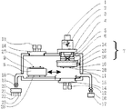
以下に本発明の望ましい第2の実施の形態について、図面を参照して説明する。図6に本発明の一実施形態に係る対向配置された被接合物を表面活性化後に減圧中で振動印加して接合する接合装置を示す。この実施形態では第1の被接合物である上ウエハーと第2の被接合物である下ウエハーを接合するための装置として例に上げる。
(Second Embodiment)
A preferred second embodiment of the present invention will be described below with reference to the drawings. FIG. 6 shows a joining apparatus according to an embodiment of the present invention, which joins an object to be joined, which is subjected to vibration activation under reduced pressure after surface activation. In this embodiment, the apparatus is exemplified as an apparatus for bonding an upper wafer as a first object to be bonded and a lower wafer as a second object to be bonded.
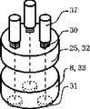
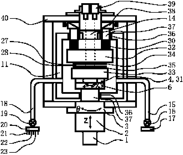
まず、装置構成について記述する。ヘッド7の一部である上ウエハーを保持する保持ツール25と下ウエハーを保持するステージ8が減圧チャンバー11中に配置され、ヘッドはトルク制御式昇降駆動モータ1が連結されたZ軸昇降機構2とZ軸昇降機構2を回転させるθ軸機構3と、ヘッド部をXY水平方向へアライメント移動させるXYアライメントテーブル6により、X、Y、θ方向のアライメント移動手段とZ方向の昇降手段からなる。保持ツール保持部24中に配置された圧力検出手段4により検出された接合時の加圧力をトルク制御式昇降駆動モータ1にフィ−ドバックすることで位置制御と圧力制御が切り替えながら行えるようになっている。また、図7に示すように、圧力検出手段4は圧力検出素子31を円周上に等間隔に3箇所配置してあり、保持ツールの平行調整用に使用したり、振動加圧時の振幅測定にも使用する。ヘッド荷重制御に使用する場合は、3つの総和を持ってサーボモータへフィードバックする。また、被接合物同士の接触検出にも利用できる。XYアライメントテーブル6は真空中でも使用できる手段を使用するが、Z、θ軸機構は減圧チャンバー外部に設置するため、Oリングやベローズ5により移動可能にヘッド部と外部を遮断されている。ヘッド及びステージの被接合物保持手段としては、メカニカルなチャッキング方式であっても良いが、静電チャックを設けることが好ましい。また、加熱のためのヒータを備え、プラズマ電極ともなっており、保持手段、加熱手段、プラズマ発生手段の3つの機能を備える。
First, the apparatus configuration will be described. A holding
図7に示すように、各保持ツールの少なくとも一方にはピエゾアクチュエータ(圧電素子)30が円周上に3箇所配置され、平行調整を行う。また、ヘッド部は接合時に超音波領域を含む振動を併用するため、ヘッド7は保持ツール保持部24、保持ツール25、振動子26から構成され、振動子による振動が保持ツールに伝達され、振動を保持ツールが保持する被接合物へ伝達する。図7に示すように、振動子となるピエゾアクチュエータ30は並列に3箇所円周上に等間隔で配置されており、位相を制御して波が流れるようなウェーブ動作や振幅も増減してうずまき動作など3次元的な動作をさせることができる。保持ツール保持部は保持ツールや振動子の振動を殺さないように保持する手段からなる。また、接合が進むにつれ接合面積に比例して加圧力を制御してやることが好ましい。また、ウエハーのような大面積を接合する場合は、横振動タイプの振動ヘッドでは横振動させるには接合面積が大きくては不可能であるが、縦振動タイプの振動ヘッドであれば、大面積な面接合も可能となる。
As shown in FIG. 7, at least one of the holding tools has three piezoelectric actuators (piezoelectric elements) 30 arranged on the circumference for parallel adjustment. In addition, since the head unit also uses vibration including an ultrasonic region at the time of joining, the head 7 includes a holding
減圧手段としては、排気管15に真空ポンプ17がつながれ、排気弁16により開閉と流量調整が行われ、真空度を調整可能な構造となっている。また、吸入側は、吸気管18に吸入ガス切り替え弁20が連結され吸気弁19により開閉と流量調整が行われる。吸入ガスとしてはプラズマの反応ガスを2種類連結でき、例えばArと酸素や酸素と窒素をつなぐことができる。もう一つは大気解放用の大気または窒素がつながれる。真空度や反応ガス濃度は吸気弁19と排気弁16の開閉含めた流量調整により最適な値に調整可能となっている。また、真空圧力センサーを減圧チャンバー内に設置することで自動フィードバックすることもできる。
As the decompression means, a
アライメント用の光学系からなるアライメントマーク認識手段がステージ待機位置の上方とヘッド下方に減圧チャンバー外部に配置される。認識手段の数は最低ステージ、ヘッド側に1つずつあれば良く、チップのような小さなものを認識するのであれば、アライメントマークがθ方向成分も読みとれる形状や2つのマークを1視野内に配置することで1つの認識手段でも十分読み取ることができるが、本実施例のようにウエハーのような半径方向に大きなものは両端に2つずつ配置した方がθ方向の精度を高く読み取ることができるので好ましい。また、認識手段は水平方向や焦点方向へ移動可能な手段を設けて、任意の位置のアライメントマークを読みとれるようにしても良い。また、認識手段は、例えば可視光やIR(赤外)光からなる光学レンズをともなったカメラからなる。減圧チャンバーには認識手段の光学系が透過できる材質、例えばガラスからなる窓が配置され、そこを透過して減圧チャンバー中の被接合物のアライメントマークを認識する。被接合物上には例えば各上ウエハー、下ウエハーの対向する表面にアライメントマークが施され位置精度良く認識することができる。アライメントマークは特定の形状であることが好ましいが、ウエハー上に施された回路パターンなどの一部を流用しても良い。また、マークとなるものが無い場合はオリフラなどの外形を利用することもできる。また、ナノレベルにより高精度にファインアライメントする場合は、粗位置決めを行った後、上ウエハーと下ウエハーを数μm程度に近接させた状態でヘッド側認識手段に可視光、IR(赤外)兼用認識手段を使用し、ステージのアライメントマーク位置には透過孔や透過材を設けることで、下部からステージを透過して両ウエハー上のアライメントマークを赤外透過して同時認識し、再度X、Y、θ方向へアライメントすることができる。認識手段が焦点方向に移動手段を持つ場合は上下個別に認識することもできるが、近接させて同時認識した方が精度上より好ましい。ファインアライメントする場合、繰り返してアライメントすることで精度向上が可能となり、また、θ方向は芯ぶれの影響が出るので一定以内に入った後はXY方向のみのアライメントを行うことでナノレベルまで精度を向上できる。画像認識手段としてはサブピクセルアルゴリズムを使用することで赤外線の解像度以上の認識精度を得ることが可能となる。また、近接させてアライメントしておけば接合時に必要なZ移動量は最低限の数μm以内となるため、Z移動に対するガタや傾きを最小限に押さえられ高精度なナノレベルの位置合わせ精度を達成することができる。 An alignment mark recognizing unit comprising an alignment optical system is disposed outside the decompression chamber above the stage standby position and below the head. The number of recognition means should be at least one on the stage and head side. If a small object such as a chip is to be recognized, the shape of the alignment mark can also read the θ direction component and two marks within one field of view. Although it is possible to read sufficiently even with one recognition means by arranging, it is possible to read with high accuracy in the θ direction when two large ones in the radial direction such as a wafer are arranged at both ends as in this embodiment. It is preferable because it is possible. Further, the recognition means may be provided with means that can move in the horizontal direction or the focal direction so that the alignment mark at an arbitrary position can be read. The recognition means is a camera with an optical lens made of, for example, visible light or IR (infrared) light. A window made of a material, for example, glass, that can be transmitted through the optical system of the recognition means is disposed in the decompression chamber, and the alignment mark of the object to be bonded in the decompression chamber is recognized through the window. For example, alignment marks are provided on the surfaces of the upper wafer and the lower wafer facing each other on the object to be bonded so that they can be recognized with high positional accuracy. The alignment mark preferably has a specific shape, but a part of a circuit pattern or the like provided on the wafer may be used. Further, when there is no mark, an outline such as an orientation flat can be used. For fine alignment with high accuracy at the nano level, after rough positioning, the head side recognition means is used for both visible light and IR (infrared) with the upper wafer and lower wafer close to about a few μm. By using a recognition means and providing a transmission hole or transmission material at the position of the alignment mark on the stage, the alignment mark on both wafers is transmitted through the stage from the bottom and transmitted through the infrared rays, and is simultaneously recognized. , Θ direction can be aligned. When the recognition means has a movement means in the focal direction, it can be recognized separately in the upper and lower directions, but it is more preferable in terms of accuracy to make the recognition close and simultaneously recognize. When fine alignment is performed, accuracy can be improved by repetitive alignment. In addition, since the θ direction is affected by the runout, the accuracy is reduced to the nano level by performing alignment only in the XY direction after entering within a certain range. It can be improved. By using a sub-pixel algorithm as an image recognition means, it is possible to obtain recognition accuracy that is higher than the infrared resolution. In addition, if they are aligned close to each other, the amount of Z movement required at the time of bonding will be within a minimum of a few μm, so the backlash and inclination with respect to Z movement can be kept to a minimum and high-precision nano-level alignment accuracy is achieved. Can be achieved.
次に動作フローを図8を参照しながら解説する。まず、〔1〕に示すように、減圧チャンバーの前扉を開いた状態で転写型となる上ウエハーと下ウエハーをステージとヘッドに保持させる。これは人手でも良いが、ウエハーはカセットから自動でローディングしても良い。次に〔2〕に示すように、前扉を閉め、減圧チャンバー内を減圧する。不純物を除去するために10−3Torr以下に減圧することが好ましい。続いてプラズマ反応ガスである例えばArを供給し、例えば10−2Torr程度の一定の真空度でプラズマ電極にプラズマ電源を印加し、プラズマを発生させる。発生されたプラズマイオンは電源側に保持されたウエハーの表面に向かって衝突し、表面の酸化膜や有機物層などの付着物がエッチングされることにより表面活性化される。また、酸素や窒素を反応ガスとして使って親水化処理し、OH基により表面活性化することもできる。同時に両ウエハーを洗浄することも可能であるが、1つのマッチングボックスを切り替えることで交互に洗浄することもできる。続いて〔3〕に示すように上ウエハーと下ウエハーを数μm程度に近接させた状態で認識手段に可視光、IR(赤外)兼用認識手段を使用し、ステージのアライメントマーク位置には透過孔や透過材を設けることで、上部からヘッドを透過して両ウエハー上のアライメントマークを同時認識してX、Y、θ方向へアライメントすることができる。この場合、繰り返してアライメントすることで精度向上が可能となり、また、θ方向は芯ぶれの影響が出るので一定以内に入った後はXY方向のみのアライメントを行うことでナノレベルまで精度を向上できる。続いて〔4〕に示すように、ステージを上昇させ、両ウエハーを接触させ、位置制御から圧力制御へと切り替え加圧する。圧力検出手段により接触を検出し高さ位置を認識しておいた状態で、圧力検出手段の値をトルク制御式昇降駆動モータにフィードバックし設定圧力になるように圧力コントロールする。初期加圧が加えられた状態でまず、円周上に等間隔で配置された圧力素子の値が均一になるようにピエゾアクチュエータで上下の被接合物間で平行調整を行う。高精度な位置決めが必要な場合は、表面活性化する前に事前に平行調整を行っておき、その値を記憶して平行調整された状態で接触させることもできる。次に前述のような3次元的な動作を含む任意の振動を印加し、接合界面での応力が増加することにより低荷重で接合が進む。加圧力は接合面積の増加に伴い比例して増加させてやることが好ましい。また、ウエハーのようにお互いに密着し合う面形状をした被接合物の接合表面には小さなゴミとなるパーティクルが存在し、低温で固層のまま接合するとパーティクル周辺に隙間ができ、大きくボイドとなって接合されない。これを除去するには接合時に振動を印加することで、パーティクル部に応力が集中するため砕けるか、基材内に埋没させることができる。また、界面の隙間からなる空隙においても振動を印加することで膨張収縮させ、空隙を接触させることで、すでに表面活性化された界面は接合されるようになり、ボイドが軽減する。超音波振動では面同士は接合できないが、接合力は表面活性化によって接合されるので振動は、パーティクルを粉砕及び/又は埋没させ、また、空隙を接触させるために使用する。真空中であるのでパーティクルさえ無くなれば隙間なく接合することができる。また、必要に応じて接合時に加熱を加える。また、残留応力を除去したり接合強度をアップするために振動接合後、加熱する場合は、常温で接触させた後、昇温させることで精度をキープさせた状態で加熱することもできる。続いて〔6〕に示すように、ステージを待機位置に戻し、減圧チャンバー内を大気解放する。続いて前扉を開けて接合されたウエハーを取り出す。人手でも良いが自動でカセットにアンローディングすることが好ましい。 Next, the operation flow will be described with reference to FIG. First, as shown in [1], with the front door of the decompression chamber opened, an upper wafer and a lower wafer, which are transfer molds, are held on a stage and a head. This may be done manually, but the wafer may be automatically loaded from the cassette. Next, as shown in [2], the front door is closed and the pressure in the vacuum chamber is reduced. In order to remove impurities, the pressure is preferably reduced to 10 −3 Torr or less. Subsequently, for example, Ar, which is a plasma reaction gas, is supplied, and a plasma power source is applied to the plasma electrode at a certain degree of vacuum, for example, about 10 −2 Torr to generate plasma. The generated plasma ions collide toward the surface of the wafer held on the power source side, and surface deposits such as an oxide film and an organic layer are etched to activate the surface. Alternatively, oxygen or nitrogen can be used as a reactive gas to make the surface hydrophilic, and the surface can be activated by OH groups. Both wafers can be cleaned at the same time, but can also be cleaned alternately by switching one matching box. Next, as shown in [3], the visible light and IR (infrared) recognizing means are used as the recognizing means with the upper wafer and the lower wafer brought close to each other by several μm, and transmitted to the alignment mark position of the stage. By providing the holes and the transmitting material, the alignment marks on both the wafers can be simultaneously recognized through the head from above and aligned in the X, Y, and θ directions. In this case, it is possible to improve accuracy by repeatedly aligning, and the θ direction is affected by the runout, so after entering within a certain range, the accuracy can be improved to the nano level by performing alignment only in the XY direction. . Subsequently, as shown in [4], the stage is raised, both wafers are brought into contact with each other, and pressure is switched from position control to pressure control. In a state where the contact is detected by the pressure detection means and the height position is recognized, the value of the pressure detection means is fed back to the torque control type lifting drive motor to control the pressure so as to become the set pressure. In a state where initial pressurization is applied, first, parallel adjustment is performed between the upper and lower workpieces by a piezo actuator so that the values of the pressure elements arranged at equal intervals on the circumference are uniform. If high-precision positioning is required, parallel adjustment can be performed in advance before surface activation, and the value can be stored and contacted in a state of parallel adjustment. Next, arbitrary vibration including the three-dimensional operation as described above is applied, and the stress at the bonding interface increases, so that the bonding proceeds with a low load. It is preferable to increase the applied pressure in proportion to the increase in the bonding area. In addition, there are particles that become small dust on the bonding surface of objects to be bonded that are in close contact with each other like a wafer, and when bonded as a solid layer at low temperature, gaps are created around the particles, and large voids and Will not be joined. In order to remove this, by applying vibration at the time of joining, since stress concentrates on the particle part, it can be crushed or buried in the base material. In addition, by applying vibration to the gap formed by the gap at the interface, the interface is already activated by bringing the gap into contact with the gap, thereby reducing the voids. The surfaces cannot be joined by ultrasonic vibration, but since the joining force is joined by surface activation, the vibration is used to pulverize and / or bury the particles and to contact the voids. Since it is in a vacuum, it can be joined without a gap if there are no particles. Further, heating is applied at the time of joining as necessary. In addition, in the case of heating after vibration bonding in order to remove residual stress or increase bonding strength, heating can be performed in a state where accuracy is maintained by raising the temperature after contacting at normal temperature. Subsequently, as shown in [6], the stage is returned to the standby position, and the inside of the decompression chamber is released to the atmosphere. Subsequently, the front door is opened and the bonded wafer is taken out. Although it may be manual, it is preferable to automatically unload the cassette.
前記実施例では被接合物としてウエハーを上げたが、チップと基板であっても良い。ウエハーのような大きな接合面積であれば、被接合物はウエハーやチップ、基板に限らずいかなる形態のものでも良い。 In the above embodiment, the wafer is raised as the object to be bonded, but it may be a chip and a substrate. As long as the bonding area is large, such as a wafer, the object to be bonded is not limited to a wafer, a chip, and a substrate, and may have any shape.
振動ヘッドをヘッドとは別にステージ待機位置とヘッド位置の中間に配置し、アライメントして上部被接合物と下部被接合物をヘッドで装着した後、ステージを移動させ、振動ヘッドにより上部より加圧、振動を印加して接合しても良い。そうすることで保持ツールで被接合物を保持する手段やプラズマ電極機能が不要となり、保持ツールの設計が容易になる。 Separately from the head, the vibration head is placed between the stage standby position and the head position, aligned, and after the upper and lower objects are mounted on the head, the stage is moved and pressurized from above by the vibration head. Alternatively, bonding may be performed by applying vibration. By doing so, the means for holding the object to be joined by the holding tool and the plasma electrode function become unnecessary, and the design of the holding tool becomes easy.
また、プラズマ洗浄を別装置で行い、本装置では接合だけを行ってもよい。その場合はステージの待機位置への移動手段は不要となる。 Further, plasma cleaning may be performed with another apparatus, and only bonding may be performed with this apparatus. In that case, the means for moving the stage to the standby position becomes unnecessary.
被接合物の保持手段としては静電チャック方式が望ましいが、メカニカルにチャッキングする方式でも良い。また、大気中でまず真空吸着保持させておいて密着させた後、メカニカルチャックする方法が密着性が上がり好ましい。 The holding means for the object to be joined is preferably an electrostatic chuck method, but may be a mechanical chucking method. In addition, a method of mechanically chucking after first vacuum-sucking and adhering in the atmosphere is preferable because adhesion is improved.
実施例ではヘッド側がアライメント移動手段と昇降軸を持ち、ステージ側がスライド軸を持ったが、アライメント移動手段、昇降軸、スライド軸はヘッド側、ステージ側にどのように組み合わせられても良く、また、重複しても良い。また、ヘッド及びステージを上下に配置しなくとも左右配置や斜めなど特に配置方向に依存しない。 In the embodiment, the head side has an alignment moving means and a lifting shaft, and the stage side has a slide shaft. However, the alignment moving means, the lifting shaft, and the slide shaft may be combined in any way on the head side and the stage side. It may be duplicated. Further, even if the head and the stage are not arranged vertically, it does not depend on the arrangement direction, such as left and right arrangement or diagonal.
ステージをスライドさせた状態でプラズマ洗浄する場合は、ヘッドとステージの電極形状、周囲の形状が似かよっているため電界環境は似かよっている。そのため、プラズマ電源を自動調整するマッチングボックスは個別のものを使用しなくとも、一つのもので電極を切り替え、順次ヘッド側、ステージ側と洗浄することができる。そうすることでコンパクト、コストダウンを達成できる。 When plasma cleaning is performed while the stage is slid, the electric field environment is similar because the electrode shape of the head and the stage and the surrounding shape are similar. Therefore, the matching box for automatically adjusting the plasma power source can be switched to the head side and the stage side sequentially by switching the electrodes by one without using an individual one. By doing so, compactness and cost reduction can be achieved.
振動周波数は特に超音波の領域でなくとも良い。特に縦振動タイプにおいては、低周波でも十分効力を発揮する。 The vibration frequency may not be in the ultrasonic region. Especially in the case of the longitudinal vibration type, the effect is sufficiently exhibited even at a low frequency.
本実施例ではArプラズマによる表面活性化を上げたが、酸素や窒素を反応ガスとしてプラズマを使用し、親水化により表面をOH基で表面活性化させ、水素結合させ、加熱により強固に共晶結合させる方法も使用できる。本方式は特にSiやガラス、SIO2、セラミック系を含む酸化物に有効である。 In this example, the surface activation by Ar plasma was increased, but plasma was used with oxygen or nitrogen as a reaction gas, the surface was activated with OH groups by hydrophilization, hydrogen-bonded, and strongly eutectic by heating. Bonding methods can also be used. This method is particularly effective for oxides including Si, glass, SIO2, and ceramics.
ピエゾアクチュエータと同側へ持っていって配置したが、図7に示すように圧力検出素子をピエゾアクチュエータと対向するステージ側へ配置した方が、被接合物を介して検出できるので好ましい。また、ピエゾアクチュエータと圧力検出配置を反対にしてもよい。また、図7のように支柱で連結して支柱をOリングで封止し、圧力検出素子を減圧チャンバー外へ配置することで温度変化によるドリフトを受けないので高精度に検出ことができる。 Although it is arranged to be held on the same side as the piezo actuator, it is preferable that the pressure detecting element is arranged on the stage side facing the piezo actuator as shown in FIG. Further, the piezoelectric actuator and the pressure detection arrangement may be reversed. Further, as shown in FIG. 7, by connecting with a support and sealing the support with an O-ring, and disposing the pressure detection element outside the decompression chamber, it is possible to detect with high accuracy because it does not receive a drift due to a temperature change.
平行調整するタイミングとしては、事前に調整した値を保持しておくこともできる。また、各接触時に平行調整したり、加圧時に修正したりすることでより緻密に行うこともできる。また、高精度に位置あわせする必要がある場合は、アライメント前に平行調整しておくことが好ましい。また、表面活性化して接合する場合は、表面活性化処理前に平行調整しておく必要がある。 As the timing of parallel adjustment, a value adjusted in advance can be held. Further, it can be performed more precisely by performing parallel adjustment at each contact or by correcting at the time of pressurization. In addition, when it is necessary to align with high accuracy, it is preferable to perform parallel adjustment before alignment. Moreover, when joining by surface activation, it is necessary to adjust in parallel before surface activation processing.
1 トルク制御式昇降駆動モータ
2 Z軸昇降機構
3 θ軸回転機構
4 圧力検出手段
5 ベローズ
6 XYアライメントテーブル
7 ヘッド
8 ステージ(プラズマ電極、ヒータ、保持手段)
9 下ウエハー
10 上ウエハー
11 真空チャンバー
12 ヘッド側ウエハー認識カメラ
13 ステージ側ウエハー認識カメラ
14 ガラス窓
15 排気管
16 排気弁
17 真空ポンプ
18 吸気管
19 吸気弁
20 吸入ガス切り替え弁
21 Ar
22 O2
23 大気
24 ホーン保持部
25 ホーン(プラズマ電極、ヒータ、保持手段)
26 振動子
27 上アライメントマーク
28 下アライメントマーク
29 スライド移動手段
30 ピエゾアクチュエータ
31 圧力検出素子
32 転写型保持ツール
33 基材保持ツール
34 転写型
35 基材
36 Oリング
37 支柱
38 平行粗銅調整部
39 アライメントマーク認識カメラ
40 フレーム
DESCRIPTION OF
9
22 O2
23
26
Claims (35)
The bonding apparatus according to any one of claims 19 to 34, wherein the object to be bonded includes a semiconductor wafer or a chip provided with a plurality of minute bumps.
Priority Applications (1)
| Application Number | Priority Date | Filing Date | Title |
|---|---|---|---|
| JP2005070327A JP2005294824A (en) | 2004-03-12 | 2005-03-14 | Ultrasonic joining method and ultrasonic joining device in vacuum |
Applications Claiming Priority (2)
| Application Number | Priority Date | Filing Date | Title |
|---|---|---|---|
| JP2004069867 | 2004-03-12 | ||
| JP2005070327A JP2005294824A (en) | 2004-03-12 | 2005-03-14 | Ultrasonic joining method and ultrasonic joining device in vacuum |
Publications (1)
| Publication Number | Publication Date |
|---|---|
| JP2005294824A true JP2005294824A (en) | 2005-10-20 |
Family
ID=35327358
Family Applications (1)
| Application Number | Title | Priority Date | Filing Date |
|---|---|---|---|
| JP2005070327A Pending JP2005294824A (en) | 2004-03-12 | 2005-03-14 | Ultrasonic joining method and ultrasonic joining device in vacuum |
Country Status (1)
| Country | Link |
|---|---|
| JP (1) | JP2005294824A (en) |
Cited By (21)
| Publication number | Priority date | Publication date | Assignee | Title |
|---|---|---|---|---|
| JP2008258426A (en) * | 2007-04-05 | 2008-10-23 | Nikon Corp | Substrate bonding apparatus, substrate bonding method, and substrate holder |
| JP2009043837A (en) * | 2007-08-07 | 2009-02-26 | Nikon Corp | Substrate bonding equipment |
| WO2009084536A1 (en) * | 2007-12-28 | 2009-07-09 | Nikon Corporation | Semiconductor substrate bonding apparatus and semiconductor substrate bonding method |
| WO2009087796A1 (en) * | 2008-01-09 | 2009-07-16 | Mitsubishi Heavy Industries, Ltd. | Cold jointing apparatus, and cold jointing method |
| JP2009164252A (en) * | 2007-12-28 | 2009-07-23 | Nikon Corp | Semiconductor wafer bonding equipment |
| JP2010177229A (en) * | 2009-01-27 | 2010-08-12 | Dainippon Screen Mfg Co Ltd | Thin-film forming apparatus |
| JPWO2009022457A1 (en) * | 2007-08-10 | 2010-11-11 | 株式会社ニコン | Substrate bonding apparatus and substrate bonding method |
| JPWO2009022469A1 (en) * | 2007-08-15 | 2010-11-11 | 株式会社ニコン | Positioning apparatus, bonding apparatus, laminated substrate manufacturing apparatus, exposure apparatus, and positioning method |
| JP2011119716A (en) * | 2009-11-04 | 2011-06-16 | Bondtech Inc | Bonding method, bonding system, and semiconductor device |
| KR101151256B1 (en) * | 2010-10-13 | 2012-06-14 | 앰코 테크놀로지 코리아 주식회사 | Stepped bonding tool and method for setting the same |
| JP2012231063A (en) * | 2011-04-27 | 2012-11-22 | Nikon Corp | Substrate bonding apparatus, substrate bonding method, and overlapped substrate |
| JP2014072249A (en) * | 2012-09-27 | 2014-04-21 | Mitsubishi Heavy Ind Ltd | Normal-temperature bonding device and normal-temperature bonding method |
| KR101414399B1 (en) * | 2006-06-22 | 2014-07-01 | 수스 마이크로텍 리소그라피 게엠바하 | Semiconductor bonding apparatus and method |
| JPWO2012133760A1 (en) * | 2011-03-30 | 2014-07-28 | ボンドテック株式会社 | Electronic component mounting method, electronic component mounting system, and substrate |
| JP2014519700A (en) * | 2011-05-11 | 2014-08-14 | エリッヒ・タールナー | Method and device for bonding two wafers |
| CN104781922A (en) * | 2012-09-07 | 2015-07-15 | 勒克斯维科技公司 | Mass transfer tool |
| US9243894B2 (en) | 2009-09-18 | 2016-01-26 | Bondtech Co., Ltd. | Pressure application apparatus and pressure application method |
| JP2017516306A (en) * | 2014-05-05 | 2017-06-15 | エーファウ・グループ・エー・タルナー・ゲーエムベーハー | Method and apparatus for continuous bonding |
| CN110040684A (en) * | 2019-05-14 | 2019-07-23 | 苏州美图半导体技术有限公司 | Automatic solution bonder |
| CN111199892A (en) * | 2018-11-20 | 2020-05-26 | 细美事有限公司 | Bonding apparatus and bonding method |
| US11370180B2 (en) | 2020-10-07 | 2022-06-28 | Kabushiki Kaisha Toshiba | Ultrasonic bonding apparatus, control device and control method |
Citations (7)
| Publication number | Priority date | Publication date | Assignee | Title |
|---|---|---|---|---|
| JPH0256916A (en) * | 1988-08-22 | 1990-02-26 | Sumitomo Metal Mining Co Ltd | Bonding method for semiconductor substrates |
| JPH06302486A (en) * | 1993-02-16 | 1994-10-28 | Nippondenso Co Ltd | Method and device for directly bonding two material |
| JP2002064042A (en) * | 2000-08-18 | 2002-02-28 | Toray Eng Co Ltd | Mounting method and device |
| JP2002210409A (en) * | 2000-11-20 | 2002-07-30 | Sony Corp | Ultrasonic vibration method and ultrasonic vibration device |
| JP2003203953A (en) * | 2002-01-08 | 2003-07-18 | Toshiba Corp | Ultrasonic bonding apparatus and its bonding method |
| JP2003318219A (en) * | 2002-02-22 | 2003-11-07 | Toray Eng Co Ltd | Mounting method and device |
| JP2004079969A (en) * | 2002-08-22 | 2004-03-11 | Toshiba Corp | Bonding equipment |
-
2005
- 2005-03-14 JP JP2005070327A patent/JP2005294824A/en active Pending
Patent Citations (7)
| Publication number | Priority date | Publication date | Assignee | Title |
|---|---|---|---|---|
| JPH0256916A (en) * | 1988-08-22 | 1990-02-26 | Sumitomo Metal Mining Co Ltd | Bonding method for semiconductor substrates |
| JPH06302486A (en) * | 1993-02-16 | 1994-10-28 | Nippondenso Co Ltd | Method and device for directly bonding two material |
| JP2002064042A (en) * | 2000-08-18 | 2002-02-28 | Toray Eng Co Ltd | Mounting method and device |
| JP2002210409A (en) * | 2000-11-20 | 2002-07-30 | Sony Corp | Ultrasonic vibration method and ultrasonic vibration device |
| JP2003203953A (en) * | 2002-01-08 | 2003-07-18 | Toshiba Corp | Ultrasonic bonding apparatus and its bonding method |
| JP2003318219A (en) * | 2002-02-22 | 2003-11-07 | Toray Eng Co Ltd | Mounting method and device |
| JP2004079969A (en) * | 2002-08-22 | 2004-03-11 | Toshiba Corp | Bonding equipment |
Cited By (33)
| Publication number | Priority date | Publication date | Assignee | Title |
|---|---|---|---|---|
| KR101414399B1 (en) * | 2006-06-22 | 2014-07-01 | 수스 마이크로텍 리소그라피 게엠바하 | Semiconductor bonding apparatus and method |
| JP2008258426A (en) * | 2007-04-05 | 2008-10-23 | Nikon Corp | Substrate bonding apparatus, substrate bonding method, and substrate holder |
| JP2009043837A (en) * | 2007-08-07 | 2009-02-26 | Nikon Corp | Substrate bonding equipment |
| US9299620B2 (en) | 2007-08-10 | 2016-03-29 | Nikon Corporation | Substrate bonding apparatus and substrate bonding method |
| KR101484348B1 (en) | 2007-08-10 | 2015-01-19 | 가부시키가이샤 니콘 | Substrate bonding apparatus and substrate bonding method |
| JPWO2009022457A1 (en) * | 2007-08-10 | 2010-11-11 | 株式会社ニコン | Substrate bonding apparatus and substrate bonding method |
| JPWO2009022469A1 (en) * | 2007-08-15 | 2010-11-11 | 株式会社ニコン | Positioning apparatus, bonding apparatus, laminated substrate manufacturing apparatus, exposure apparatus, and positioning method |
| WO2009084536A1 (en) * | 2007-12-28 | 2009-07-09 | Nikon Corporation | Semiconductor substrate bonding apparatus and semiconductor substrate bonding method |
| JP2009164252A (en) * | 2007-12-28 | 2009-07-23 | Nikon Corp | Semiconductor wafer bonding equipment |
| JP5365525B2 (en) * | 2007-12-28 | 2013-12-11 | 株式会社ニコン | Semiconductor substrate bonding apparatus and semiconductor substrate bonding method |
| WO2009087796A1 (en) * | 2008-01-09 | 2009-07-16 | Mitsubishi Heavy Industries, Ltd. | Cold jointing apparatus, and cold jointing method |
| US8985175B2 (en) | 2008-01-09 | 2015-03-24 | Mitsubishi Heavy Industries, Ltd. | Room temperature bonding machine and room temperature bonding method |
| JP2010177229A (en) * | 2009-01-27 | 2010-08-12 | Dainippon Screen Mfg Co Ltd | Thin-film forming apparatus |
| US9379082B2 (en) | 2009-09-18 | 2016-06-28 | Bondtech Co., Ltd. | Pressure application apparatus and pressure application method |
| US9243894B2 (en) | 2009-09-18 | 2016-01-26 | Bondtech Co., Ltd. | Pressure application apparatus and pressure application method |
| JP2011119716A (en) * | 2009-11-04 | 2011-06-16 | Bondtech Inc | Bonding method, bonding system, and semiconductor device |
| KR101151256B1 (en) * | 2010-10-13 | 2012-06-14 | 앰코 테크놀로지 코리아 주식회사 | Stepped bonding tool and method for setting the same |
| JPWO2012133760A1 (en) * | 2011-03-30 | 2014-07-28 | ボンドテック株式会社 | Electronic component mounting method, electronic component mounting system, and substrate |
| JP2012231063A (en) * | 2011-04-27 | 2012-11-22 | Nikon Corp | Substrate bonding apparatus, substrate bonding method, and overlapped substrate |
| JP2014519700A (en) * | 2011-05-11 | 2014-08-14 | エリッヒ・タールナー | Method and device for bonding two wafers |
| CN104781922B (en) * | 2012-09-07 | 2017-04-26 | 苹果公司 | Mass transfer tool |
| CN104781922A (en) * | 2012-09-07 | 2015-07-15 | 勒克斯维科技公司 | Mass transfer tool |
| JP2015529400A (en) * | 2012-09-07 | 2015-10-05 | ルクスビュー テクノロジー コーポレイション | Mass transfer tool |
| US10183401B2 (en) | 2012-09-07 | 2019-01-22 | Apple Inc. | Mass transfer tool |
| US9511498B2 (en) | 2012-09-07 | 2016-12-06 | Apple Inc. | Mass transfer tool |
| US9580306B2 (en) | 2012-09-27 | 2017-02-28 | Mitsubishi Heavy Industries Machine Tool Co., Ltd. | Room temperature bonding apparatus and room temperature bonding method |
| JP2014072249A (en) * | 2012-09-27 | 2014-04-21 | Mitsubishi Heavy Ind Ltd | Normal-temperature bonding device and normal-temperature bonding method |
| JP2017516306A (en) * | 2014-05-05 | 2017-06-15 | エーファウ・グループ・エー・タルナー・ゲーエムベーハー | Method and apparatus for continuous bonding |
| CN111199892A (en) * | 2018-11-20 | 2020-05-26 | 细美事有限公司 | Bonding apparatus and bonding method |
| CN111199892B (en) * | 2018-11-20 | 2023-08-18 | 细美事有限公司 | Bonding device and bonding method |
| CN110040684A (en) * | 2019-05-14 | 2019-07-23 | 苏州美图半导体技术有限公司 | Automatic solution bonder |
| CN110040684B (en) * | 2019-05-14 | 2024-04-09 | 苏州美图半导体技术有限公司 | Automatic bond-releasing machine |
| US11370180B2 (en) | 2020-10-07 | 2022-06-28 | Kabushiki Kaisha Toshiba | Ultrasonic bonding apparatus, control device and control method |
Similar Documents
| Publication | Publication Date | Title |
|---|---|---|
| JP2005294824A (en) | Ultrasonic joining method and ultrasonic joining device in vacuum | |
| JP3790995B2 (en) | JOINING METHOD, DEVICE PRODUCED BY THIS METHOD, AND JOINING DEVICE | |
| JP7420185B2 (en) | Board bonding equipment and board bonding method | |
| JP3751972B2 (en) | JOINING METHOD, DEVICE PRODUCED BY THIS METHOD, SURFACE ACTIVATION DEVICE, AND JOINING DEVICE PROVIDED WITH THIS DEVICE | |
| JP4919604B2 (en) | Joining method and joining apparatus | |
| JP2006116602A (en) | Parallelism regulating method and device for pressurizing apparatus | |
| US20070110917A1 (en) | Bonding method, device formed by such method, surface activating unit and bonding apparatus comprising such unit | |
| WO2005054147A1 (en) | Bonding method, device produced by this method, and bonding device | |
| WO2022181655A1 (en) | Bonding method, substrate bonding device, and substrate bonding system | |
| JP4686377B2 (en) | Joining method and joining apparatus | |
| JP3820409B2 (en) | JOINING METHOD, DEVICE PRODUCED BY THIS METHOD, AND JOINING DEVICE | |
| JP2005142537A (en) | Vertical vibration welding method and apparatus | |
| JP5181158B2 (en) | Bonding method, device produced by this method, and bonding apparatus | |
| JP4669766B2 (en) | POSITIONING METHOD, PRESSURE METHOD AND POSITIONING DEVICE USING THE METHOD, PRESSURE DEVICE EQUIPPED WITH THE DEVICE | |
| JP2006248895A (en) | JOINING METHOD, DEVICE PRODUCED BY THIS METHOD, AND JOINING DEVICE | |
| JP5438734B2 (en) | Joining method | |
| JP4979918B2 (en) | Pressurizing method and pressurizing apparatus | |
| JP2003249425A (en) | Mounting method and apparatus | |
| JP2005229005A (en) | Ultrasonic bonding method and apparatus in vacuum | |
| JP2006134899A (en) | Joining method and apparatus | |
| US20260054329A1 (en) | Substrate bonding system and substrate bonding method | |
| JP3773201B2 (en) | Delivery method and apparatus for workpieces | |
| JP2007088241A (en) | Pressing device and pressing method | |
| JP2006080100A (en) | Joining method and apparatus | |
| JP2006073780A (en) | Normal-temperature joint method, equipment, and device |
Legal Events
| Date | Code | Title | Description |
|---|---|---|---|
| RD02 | Notification of acceptance of power of attorney |
Free format text: JAPANESE INTERMEDIATE CODE: A7422 Effective date: 20050801 |
|
| A521 | Written amendment |
Free format text: JAPANESE INTERMEDIATE CODE: A523 Effective date: 20050802 |
|
| A521 | Written amendment |
Free format text: JAPANESE INTERMEDIATE CODE: A821 Effective date: 20050802 |
|
| A521 | Written amendment |
Free format text: JAPANESE INTERMEDIATE CODE: A523 Effective date: 20070529 |
|
| A711 | Notification of change in applicant |
Free format text: JAPANESE INTERMEDIATE CODE: A711 Effective date: 20070529 |
|
| A521 | Written amendment |
Free format text: JAPANESE INTERMEDIATE CODE: A821 Effective date: 20070529 |
|
| A621 | Written request for application examination |
Free format text: JAPANESE INTERMEDIATE CODE: A621 Effective date: 20080305 |
|
| A977 | Report on retrieval |
Free format text: JAPANESE INTERMEDIATE CODE: A971007 Effective date: 20111228 |
|
| A131 | Notification of reasons for refusal |
Free format text: JAPANESE INTERMEDIATE CODE: A131 Effective date: 20120110 |
|
| A02 | Decision of refusal |
Free format text: JAPANESE INTERMEDIATE CODE: A02 Effective date: 20120731 |