JP2005291995A - 無端金属ベルト用リングの疲労試験装置および疲労試験方法 - Google Patents
無端金属ベルト用リングの疲労試験装置および疲労試験方法 Download PDFInfo
- Publication number
- JP2005291995A JP2005291995A JP2004109066A JP2004109066A JP2005291995A JP 2005291995 A JP2005291995 A JP 2005291995A JP 2004109066 A JP2004109066 A JP 2004109066A JP 2004109066 A JP2004109066 A JP 2004109066A JP 2005291995 A JP2005291995 A JP 2005291995A
- Authority
- JP
- Japan
- Prior art keywords
- ring
- roller
- fatigue test
- fatigue
- endless metal
- Prior art date
- Legal status (The legal status is an assumption and is not a legal conclusion. Google has not performed a legal analysis and makes no representation as to the accuracy of the status listed.)
- Granted
Links
Images

Landscapes
- Testing Of Devices, Machine Parts, Or Other Structures Thereof (AREA)
- Investigating Strength Of Materials By Application Of Mechanical Stress (AREA)
Abstract
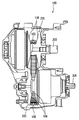
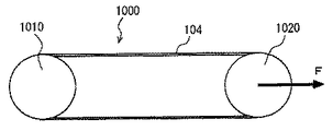
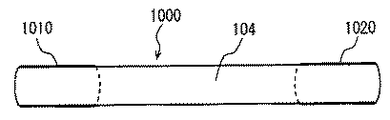
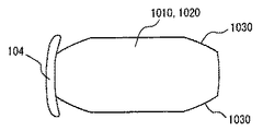
【解決手段】 疲労試験装置は、無端金属ベルト用のリングの疲労強度を試験する。疲労試験装置は、疲労試験対象のリングが巻き掛けられ、そのリングに所定の引張り応力および曲げ応力を付与して所定の速度で回転させる第1ローラ1010および第2ローラ1020を含む。第1ローラ1010および第2ローラ1020は、エレメントの首部とサドル面との間に設けられた窪みよりも大きな溝部であるローラ端部1030を有し、この端部1030により、リング104の一部のみが第1ローラ1010および第2ローラ1020に巻き掛けられることになり、端部に発生する引張り応力を抑制でき、リング104に発生する応力振幅を大きくすることができ、疲労強度の試験時間を短縮できる。
【選択図】 図9
Description
Claims (6)
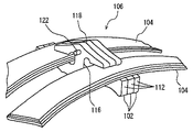
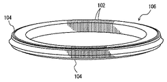
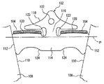
- サドル部、頂部およびこれらをつなぐ首部とから構成されるとともに前記サドル部と前記首部との間に窪みが設けられた複数のエレメントをその板厚方向に並べて、前記エレメントのサドル部および頂部の間に環状のリングを通すことにより構成された無端金属ベルトにおける前記リングに適用される疲労試験装置であって、
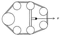
前記リングが掛けられるとともに軸間力が付与される複数のローラと、
前記複数のローラの中の少なくとも1つのローラを回転させるための回転手段とを含み、
前記複数のローラは、前記リング端面に対する前記窪みの比率よりも大きな比率の模擬窪みを有する、無端金属ベルト用リングの疲労試験装置。 - 前記模擬窪みにより、前記ローラと前記リングとの接触面積は、前記エレメントと前記リングとの接触面積よりも小さくなる、請求項1に記載の疲労試験装置。
- 前記模擬窪みにより、前記ローラに巻き掛けられた前記リングの端部における引張り応力が低くなる、請求項1に記載の疲労試験装置。
- サドル部、頂部およびこれらをつなぐ首部とから構成されるとともに前記サドル部と前記首部との間に窪みが設けられた複数のエレメントをその板厚方向に並べて、前記エレメントのサドル部および頂部の間に環状のリングを通すことにより構成された無端金属ベルトにおける前記リングに適用される疲労試験方法であって、
前記リングを、前記リング端面に対する前記窪みの比率よりも大きな比率の模擬窪みを有する複数のローラに掛けるステップと、
前記ローラに軸間力を付与することにより、前記リングに引張り応力を付与する引張りステップと、
前記複数のローラの少なくとも1つのローラを回転させることにより、前記リングに繰返し曲げ応力を付与する曲げステップとを含む、無端金属ベルト用リングの疲労試験方法。 - 前記模擬窪みにより、前記ローラと前記リングとの接触面積は、前記エレメントと前記リングとの接触面積よりも小さくなる、請求項4に記載の疲労試験方法。
- 前記模擬窪みにより、前記ローラに巻き掛けられた前記リングの端部における引張り応力が低くなる、請求項4に記載の疲労試験方法。
Priority Applications (1)
| Application Number | Priority Date | Filing Date | Title |
|---|---|---|---|
| JP2004109066A JP4161928B2 (ja) | 2004-04-01 | 2004-04-01 | 無端金属ベルト用リングの疲労試験装置および疲労試験方法 |
Applications Claiming Priority (1)
| Application Number | Priority Date | Filing Date | Title |
|---|---|---|---|
| JP2004109066A JP4161928B2 (ja) | 2004-04-01 | 2004-04-01 | 無端金属ベルト用リングの疲労試験装置および疲労試験方法 |
Publications (2)
| Publication Number | Publication Date |
|---|---|
| JP2005291995A true JP2005291995A (ja) | 2005-10-20 |
| JP4161928B2 JP4161928B2 (ja) | 2008-10-08 |
Family
ID=35325079
Family Applications (1)
| Application Number | Title | Priority Date | Filing Date |
|---|---|---|---|
| JP2004109066A Expired - Fee Related JP4161928B2 (ja) | 2004-04-01 | 2004-04-01 | 無端金属ベルト用リングの疲労試験装置および疲労試験方法 |
Country Status (1)
| Country | Link |
|---|---|
| JP (1) | JP4161928B2 (ja) |
Cited By (2)
| Publication number | Priority date | Publication date | Assignee | Title |
|---|---|---|---|---|
| CN108287113A (zh) * | 2018-02-09 | 2018-07-17 | 西南交通大学 | 一种用于边坡防护结构中圆环构件的试验设备 |
| CN114729864A (zh) * | 2020-06-23 | 2022-07-08 | 株式会社Lg新能源 | 用于金属箔的疲劳测试设备和使用所述疲劳测试设备的方法 |
-
2004
- 2004-04-01 JP JP2004109066A patent/JP4161928B2/ja not_active Expired - Fee Related
Cited By (5)
| Publication number | Priority date | Publication date | Assignee | Title |
|---|---|---|---|---|
| CN108287113A (zh) * | 2018-02-09 | 2018-07-17 | 西南交通大学 | 一种用于边坡防护结构中圆环构件的试验设备 |
| CN108287113B (zh) * | 2018-02-09 | 2024-06-04 | 西南交通大学 | 一种用于边坡防护结构中圆环构件的试验设备 |
| CN114729864A (zh) * | 2020-06-23 | 2022-07-08 | 株式会社Lg新能源 | 用于金属箔的疲劳测试设备和使用所述疲劳测试设备的方法 |
| US12292418B2 (en) | 2020-06-23 | 2025-05-06 | Lg Energy Solution, Ltd. | Fatigue testing apparatus for metallic foil and method using same |
| CN114729864B (zh) * | 2020-06-23 | 2026-04-10 | 株式会社Lg新能源 | 用于金属箔的疲劳测试设备和使用所述疲劳测试设备的方法 |
Also Published As
| Publication number | Publication date |
|---|---|
| JP4161928B2 (ja) | 2008-10-08 |
Similar Documents
| Publication | Publication Date | Title |
|---|---|---|
| US20070191157A1 (en) | Method of pretensioning power transmission chain,device for said method and power transmission apparatus | |
| US8863368B2 (en) | Winding member manufacturing method, winding member manufacturing apparatus, winding member peripheral length measuring apparatus and pre-tension applying apparatus | |
| JP5347290B2 (ja) | 動力伝達チェーンの予張方法 | |
| JP4161928B2 (ja) | 無端金属ベルト用リングの疲労試験装置および疲労試験方法 | |
| JP4898107B2 (ja) | 動力伝達チェーンの製造方法 | |
| JP3912291B2 (ja) | 無端金属ベルト用リングの疲労試験装置および疲労試験方法 | |
| JP2009115591A (ja) | 動力伝達チェーンの検査方法および検査装置 | |
| JP4770454B2 (ja) | 無段変速機用動力伝達チェーンの製造方法 | |
| JP4292807B2 (ja) | 無端金属ベルト用リングの耐摩耗性評価方法 | |
| JP2007270942A (ja) | 動力伝達チェーン及び動力伝達装置 | |
| JP5035514B2 (ja) | 動力伝達チェーンの製造方法および製造装置 | |
| JP2009028737A (ja) | 動力伝達チェーンの予張方法および予張装置 | |
| JP4853017B2 (ja) | 動力伝達チェーンおよびその製造方法ならびに動力伝達装置 | |
| JP4893561B2 (ja) | 動力伝達チェーンおよび動力伝達装置 | |
| JP2008111494A (ja) | 動力伝達チェーンの製造方法および製造装置 | |
| JP2009255121A (ja) | 動力伝達チェーンの予張方法および予張装置 | |
| JP4770610B2 (ja) | 動力伝達チェーンおよび動力伝達装置 | |
| JP2008168301A (ja) | 動力伝達チェーンの製造方法および製造装置 | |
| JP2008144824A (ja) | 動力伝達チェーンの製造方法および製造装置 | |
| JP5151140B2 (ja) | 動力伝達チェーンおよび動力伝達装置 | |
| JP4821392B2 (ja) | 動力伝達チェーンの設計方法、動力伝達チェーンおよび動力伝達装置 | |
| JP2008238226A (ja) | 動力伝達チェーンの予張方法および予張治具 | |
| JP2008267577A (ja) | 動力伝達チェーンの予張方法および予張装置 | |
| JP2011200874A (ja) | 動力伝達チェーンの製造方法 | |
| JP2008138768A (ja) | 動力伝達チェーンの応力付与方法、その方法に使用する応力付与装置 |
Legal Events
| Date | Code | Title | Description |
|---|---|---|---|
| A621 | Written request for application examination |
Free format text: JAPANESE INTERMEDIATE CODE: A621 Effective date: 20060823 |
|
| A977 | Report on retrieval |
Free format text: JAPANESE INTERMEDIATE CODE: A971007 Effective date: 20080204 |
|
| A131 | Notification of reasons for refusal |
Free format text: JAPANESE INTERMEDIATE CODE: A131 Effective date: 20080212 |
|
| A521 | Written amendment |
Free format text: JAPANESE INTERMEDIATE CODE: A523 Effective date: 20080407 |
|
| A131 | Notification of reasons for refusal |
Free format text: JAPANESE INTERMEDIATE CODE: A131 Effective date: 20080507 |
|
| A521 | Written amendment |
Free format text: JAPANESE INTERMEDIATE CODE: A523 Effective date: 20080603 |
|
| TRDD | Decision of grant or rejection written | ||
| A01 | Written decision to grant a patent or to grant a registration (utility model) |
Free format text: JAPANESE INTERMEDIATE CODE: A01 Effective date: 20080701 |
|
| A01 | Written decision to grant a patent or to grant a registration (utility model) |
Free format text: JAPANESE INTERMEDIATE CODE: A01 |
|
| A61 | First payment of annual fees (during grant procedure) |
Free format text: JAPANESE INTERMEDIATE CODE: A61 Effective date: 20080714 |
|
| FPAY | Renewal fee payment (event date is renewal date of database) |
Free format text: PAYMENT UNTIL: 20110801 Year of fee payment: 3 |
|
| R151 | Written notification of patent or utility model registration |
Ref document number: 4161928 Country of ref document: JP Free format text: JAPANESE INTERMEDIATE CODE: R151 |
|
| FPAY | Renewal fee payment (event date is renewal date of database) |
Free format text: PAYMENT UNTIL: 20110801 Year of fee payment: 3 |
|
| FPAY | Renewal fee payment (event date is renewal date of database) |
Free format text: PAYMENT UNTIL: 20110801 Year of fee payment: 3 |
|
| FPAY | Renewal fee payment (event date is renewal date of database) |
Free format text: PAYMENT UNTIL: 20120801 Year of fee payment: 4 |
|
| FPAY | Renewal fee payment (event date is renewal date of database) |
Free format text: PAYMENT UNTIL: 20130801 Year of fee payment: 5 |
|
| LAPS | Cancellation because of no payment of annual fees |