JP2005291995A - Endless metal belt ring fatigue testing apparatus and fatigue testing method - Google Patents
Endless metal belt ring fatigue testing apparatus and fatigue testing method Download PDFInfo
- Publication number
- JP2005291995A JP2005291995A JP2004109066A JP2004109066A JP2005291995A JP 2005291995 A JP2005291995 A JP 2005291995A JP 2004109066 A JP2004109066 A JP 2004109066A JP 2004109066 A JP2004109066 A JP 2004109066A JP 2005291995 A JP2005291995 A JP 2005291995A
- Authority
- JP
- Japan
- Prior art keywords
- ring
- roller
- fatigue test
- fatigue
- endless metal
- Prior art date
- Legal status (The legal status is an assumption and is not a legal conclusion. Google has not performed a legal analysis and makes no representation as to the accuracy of the status listed.)
- Granted
Links
Images

Landscapes
- Testing Of Devices, Machine Parts, Or Other Structures Thereof (AREA)
- Investigating Strength Of Materials By Application Of Mechanical Stress (AREA)
Abstract
【課題】 CVTに用いられる無端金属ベルト用のリングの疲労強度試験時間を短縮する。
【解決手段】 疲労試験装置は、無端金属ベルト用のリングの疲労強度を試験する。疲労試験装置は、疲労試験対象のリングが巻き掛けられ、そのリングに所定の引張り応力および曲げ応力を付与して所定の速度で回転させる第1ローラ1010および第2ローラ1020を含む。第1ローラ1010および第2ローラ1020は、エレメントの首部とサドル面との間に設けられた窪みよりも大きな溝部であるローラ端部1030を有し、この端部1030により、リング104の一部のみが第1ローラ1010および第2ローラ1020に巻き掛けられることになり、端部に発生する引張り応力を抑制でき、リング104に発生する応力振幅を大きくすることができ、疲労強度の試験時間を短縮できる。
【選択図】 図9PROBLEM TO BE SOLVED: To shorten a fatigue strength test time of an endless metal belt ring used in CVT.
A fatigue test apparatus tests the fatigue strength of a ring for an endless metal belt. The fatigue test apparatus includes a first roller 1010 and a second roller 1020 around which a ring to be subjected to a fatigue test is wound and which is rotated at a predetermined speed by applying predetermined tensile stress and bending stress to the ring. The first roller 1010 and the second roller 1020 have a roller end portion 1030 that is a groove portion larger than a recess provided between the neck portion and the saddle surface of the element. Only the first roller 1010 and the second roller 1020 are wound, the tensile stress generated at the end portion can be suppressed, the stress amplitude generated in the ring 104 can be increased, and the fatigue strength test time can be increased. Can be shortened.
[Selection] Figure 9
Description
本発明は、板片状の多数のエレメントを互いに対面させて環状に配置し、それらのエレメントに金属帯であるリングを通して各エレメントを環状に結束して構成した無端金属ベルトの疲労試験技術に関し、特に、リング単体の疲労試験技術に関する。 The present invention relates to a fatigue test technique for an endless metal belt in which a large number of plate-like elements are arranged in an annular shape so as to face each other, and each element is annularly bound to each other through a ring that is a metal strip. In particular, it relates to a fatigue test technique for a single ring.
車両においては、トランスミッションの変速比を車両の走行状況に応じて無段階に調整するベルト式無段変速機(CVT:Continuously Variable Transmission)が搭載されることがある。このCVTは、エンジン出力を効率的に引き出すことが可能であり、燃費および走行性能の向上に優れる。実用化されたCVTの1つとして、金属ベルトと一対のプーリとを用いて、油圧によってプーリの有効径を変化させることで連続的に無段の変速を実現するものがある。無端金属ベルトが、入力軸に取付けられた入力側プーリおよび出力軸に取付けられた出力側プーリに巻き掛けられて使用される。入力側プーリおよび出力側プーリは、溝幅を無段階に変えられる1対のシーブをそれぞれ備え、溝幅を変えることで、無端金属ベルトの入力側プーリおよび出力側プーリに対する巻付け半径が変わり、これにより入力軸と出力軸との間の回転数比、すなわち変速比を連続的に無段階に変化させることができる。 A vehicle may be equipped with a belt-type continuously variable transmission (CVT) that continuously adjusts the transmission gear ratio in accordance with the traveling state of the vehicle. This CVT can efficiently draw out the engine output, and is excellent in improving fuel consumption and running performance. One of the CVTs that have been put into practical use is one that uses a metal belt and a pair of pulleys to change the effective diameter of the pulleys by hydraulic pressure, thereby realizing a continuously variable transmission. An endless metal belt is wound around an input side pulley attached to the input shaft and an output side pulley attached to the output shaft. The input side pulley and the output side pulley are each provided with a pair of sheaves whose groove width can be changed steplessly. By changing the groove width, the winding radius of the endless metal belt with respect to the input side pulley and the output side pulley changes, Thereby, the rotation speed ratio between the input shaft and the output shaft, that is, the gear ratio can be continuously changed continuously.
この無端金属ベルトは、厚さの異なる複数の種類のエレメントを準備し、これら複数の種類のエレメントを予め定められた個数の比率でランダムに組合せる。組合せたエレメントに金属帯を通すことにより無端金属ベルトが製造される。このような金属帯であるリングの疲労強度は無端金属ベルトの耐久性に大きな影響を与えることから、リングの疲労試験が行なわれている。 In this endless metal belt, a plurality of types of elements having different thicknesses are prepared, and the plurality of types of elements are randomly combined at a predetermined number ratio. An endless metal belt is produced by passing a metal strip through the combined elements. The fatigue strength of the ring, which is such a metal band, has a great influence on the durability of the endless metal belt, and therefore, a ring fatigue test is performed.
特開2002−243605号公報(特許文献1)は、回転曲げによる疲労と摩擦による疲労とを同時にかつ迅速に試験することができ、欠陥の存在確率が低い場合でさえも欠陥部位での破損を再現することができる回転曲げ摩擦試験装置を開示する。この回転曲げ摩擦試験装置は、互いに異なる周速で回転する複数の回転ローラを備え、回転ローラに巻き掛けられた環状試験片に張力を与えながら、環状試験片を回転させることを特徴とする。 Japanese Patent Laid-Open No. 2002-243605 (Patent Document 1) can simultaneously and quickly test fatigue due to rotational bending and fatigue due to friction, and even if the probability of existence of a defect is low, damage at the defect site is detected. Disclosed is a rotating bending friction test apparatus that can be reproduced. This rotating bending friction test apparatus includes a plurality of rotating rollers that rotate at different peripheral speeds, and rotates the annular test piece while applying tension to the annular test piece wound around the rotating roller.
この回転曲げ摩擦試験装置によると、異なる周速で回転する複数の回転ローラを用いることにより、回転ローラと環状試験片との間に滑りを生じさせて、環状試験片の内側に摩擦による応力を作用させることができるため、回転曲げ疲労と摩擦疲労とを同時に付与することができ、より実際の使用環境に近い条件での環状試験片の疲労試験を行なうことができる。 According to this rotating bending friction test apparatus, by using a plurality of rotating rollers that rotate at different peripheral speeds, slip occurs between the rotating roller and the annular test piece, and stress due to friction is applied to the inner side of the annular test piece. Therefore, rotational bending fatigue and friction fatigue can be imparted simultaneously, and a fatigue test of the annular test piece can be performed under conditions closer to the actual use environment.
実開平5−17543号公報(特許文献2)は、車両における無段変速機における過酷な変速操作の繰り返し荷重とほぼ同等の条件で試験することができる無段変速機用Vベルトの疲労試験用治具を開示する。この無段変速機用Vベルトの疲労試験用治具は、加振機上に取り付けられた基板に支柱を立設し、この支柱と所定の距離を隔てて2本のネジボルトを立設するとともに、支柱の上端には一端部を枢着してネジボルト間に延出する支持バーを設けて同端部にウエイトを着脱可能に設け、ネジボルトの上部にはスパンを上下に位置調整可能に設けてウエイトとの間にコイルスプリングを介してロードセルを弾着し、また、支柱とネジボルトとの間の所定の位置には所定の角度の傾斜面を有し、かつ試料片を取付可能なV溝を有するVブロックを立設し、このVブロックと対応する支持バーには先端がVブロックのV溝に挿入され、かつ傾斜面と平行で試料片に当接する受け面を有する作動アームを設けて、支持バーとウエイトによるてこ作用により作動アームの先端で試料片に繰り返し増減荷重を負荷可能に構成することを特徴とする。 Japanese Utility Model Laid-Open No. 5-17543 (Patent Document 2) is for a fatigue test of a continuously variable transmission V-belt that can be tested under substantially the same conditions as a repeated load of a severe shift operation in a continuously variable transmission in a vehicle. A jig is disclosed. This V-belt fatigue test jig for continuously variable transmissions has a column installed upright on a substrate mounted on a vibration exciter, and two screw bolts are installed at a predetermined distance from this column. The upper end of the strut has a support bar that is pivotally attached at one end and extends between the screw bolts, and a weight can be attached and detached at the same end, and a span can be adjusted up and down at the top of the screw bolt. A load cell is impacted between a weight and a coil spring, and a V-groove having an inclined surface at a predetermined angle at a predetermined position between a support column and a screw bolt and to which a sample piece can be attached. The support bar corresponding to this V block is provided with an operating arm having a receiving surface that is inserted into the V groove of the V block and has a receiving surface that is parallel to the inclined surface and abuts against the sample piece. By lever action with support bar and weight Characterized by load configured to be able to repeatedly increase and decrease the load on the sample pieces at a distal end of the actuating arm.
この無段変速機用Vベルトの疲労試験用治具によると、試料片の断面に対し垂直方向と側面方向の2方向より繰り返し増減荷重を与えることができる。
特許文献1に開示された回転曲げ摩擦試験装置において、迅速な疲労試験を行なうためには、1)試験装置のローラの回転数(繰返し速度)を上昇させること、2)6個程度を限界として回転ローラ数を増やすこと、により実現している。しかしながら、このような手法では、たとえばベルトが破断するまでの疲労試験を著しく短縮するのは困難である。 In the rotary bending friction test apparatus disclosed in Patent Document 1, in order to perform a quick fatigue test, 1) increase the number of rotations (repetition speed) of the rollers of the test apparatus, and 2) limit about six. This is achieved by increasing the number of rotating rollers. However, with such a technique, it is difficult to significantly shorten the fatigue test until the belt breaks, for example.
特許文献2に開示された疲労試験用治具は、CVTベルト用の試料片を垂直方向に対し所定の角度θで設けた受けブロックの受け面に沿ってセットしたものである。これにより、倍率的に作用する垂直荷重は試料片に対し2方向の分力が作用することとなり、この2方向の分力は加振機の振動によりウエイトの荷重が動的に増減し、さらに、てこの原理により倍率的に大きな増減荷重として試料片に作用して、無段変速機における過酷な変速操作の繰り返し荷重と同等の負荷を与えることができて、摩耗、変形等の疲労状態を測定することができる。しかしながら、このような試料片の疲労状態を測定するに過ぎず、実際のベルトの形状に加工された場合の疲労状態を測定することはできない。 The fatigue test jig disclosed in Patent Document 2 is a sample set for a CVT belt set along a receiving surface of a receiving block provided at a predetermined angle θ with respect to the vertical direction. As a result, the vertical load acting as a magnification has two component forces acting on the specimen, and the two component forces dynamically increase / decrease the weight load due to the vibration of the vibrator. According to the lever principle, it can act on the sample piece as a large increase / decrease load in magnification, and can give a load equivalent to the repeated load of severe shifting operation in a continuously variable transmission, and can reduce fatigue conditions such as wear and deformation. Can be measured. However, only the fatigue state of such a sample piece is measured, and the fatigue state when processed into an actual belt shape cannot be measured.
本発明は、上述の課題を解決するためになされたものであって、その目的は、実際の使用状況を模擬して無端金属ベルトを構成するリングの疲労状態を短時間で判定できる、無端金属ベルト用リングの疲労試験装置および疲労試験方法を提供することである。 The present invention has been made to solve the above-mentioned problems, and its object is to endlessly determine the fatigue state of a ring constituting an endless metal belt in a short time by simulating actual usage conditions. To provide a fatigue test apparatus and a fatigue test method for a belt ring.
第1の発明に係る無端金属ベルト用リングの疲労試験装置は、リングが掛けられるとともに軸間力が付与される複数のローラと、複数のローラの中の少なくとも1つのローラを回転させるための回転手段とを含む。複数のローラは、リング端面に対する窪みの比率よりも大きな比率の模擬窪みを有する。 A fatigue test apparatus for an endless metal belt ring according to a first aspect of the present invention includes a plurality of rollers on which a ring is applied and an interaxial force is applied, and rotation for rotating at least one of the plurality of rollers. Means. The plurality of rollers have simulated depressions with a ratio larger than the ratio of the depressions with respect to the ring end surface.
第1の発明によると、この疲労試験装置は、サドル部、頂部およびこれらをつなぐ首部とから構成されるとともにサドル部と首部との間に窪みが設けられた複数のエレメントをその板厚方向に並べて、エレメントのサドル部および頂部の間に環状のリングを通すことにより構成された無端金属ベルトにおけるリングに適用される。この疲労試験装置のローラは、模擬窪みを有する。この模擬窪みはエレメントの窪みよりも大きな溝などで構成される。このため、エレメントのサドル部にベルトが接触する実際の使用状態に対して、ローラにはリングの中央部しか接触しない状態になる(すなわち、リングがかかっているローラの幅が実際よりも小さくなる)。このため、ローラに巻き掛かっているリング端部に引張り応力が作用しにくくなり、端部の応力が低く抑制される。これは、ローラにおける端部引張り応力の抜けが大きくなることを示す。これにより、リング中央部とリング端部との応力振幅が大きくなる。これは、実際のエレメントの状態と同じ状態では、リングの破断までに長い時間を必要とするが、このように応力振幅を大きくした状態で疲労状態を試験するので、短時間でリング単体の疲労試験を終えることができることを示す。その結果、実際の使用状況を模擬して無端金属ベルトを構成するリングの疲労状態を短時間で判定できる、無端金属ベルト用リングの疲労試験装置を提供することができる。 According to the first invention, this fatigue test apparatus comprises a saddle portion, a top portion, and a neck portion connecting them, and a plurality of elements provided with depressions between the saddle portion and the neck portion in the plate thickness direction. It is applied to the ring in an endless metal belt constructed by passing an annular ring between the saddle and top of the element side by side. The roller of this fatigue test apparatus has a simulated depression. This simulated depression is composed of a groove larger than the depression of the element. Therefore, in contrast to the actual use state in which the belt contacts the saddle portion of the element, the roller is in contact with only the center portion of the ring (that is, the width of the roller on which the ring is applied is smaller than the actual width). ). For this reason, it becomes difficult for a tensile stress to act on the ring end part wound around the roller, and the stress at the end part is suppressed to a low level. This indicates that the end tensile stress loss in the roller increases. As a result, the stress amplitude between the ring center portion and the ring end portion increases. In the same state as the actual element state, it takes a long time until the ring breaks. However, since the fatigue state is tested in such a state that the stress amplitude is increased, the fatigue of the ring itself is shortened in a short time. Indicates that the test can be completed. As a result, it is possible to provide an endless metal belt ring fatigue test apparatus that can determine the fatigue state of the ring constituting the endless metal belt in a short time by simulating actual use conditions.
第2の発明に係る疲労試験装置においては、第1の発明の構成に加えて、模擬窪みにより、ローラとリングとの接触面積は、エレメントとリングとの接触面積よりも小さくなるものである。 In the fatigue testing apparatus according to the second invention, in addition to the configuration of the first invention, the contact area between the roller and the ring is smaller than the contact area between the element and the ring due to the simulated depression.
第2の発明によると、模擬窪みにより、ローラとリングとの接触面積は、エレメントとリングとの接触面積よりも小さくなり、リング端部はローラに巻き掛かっていないことになり、端部の応力が低く抑制される。これにより、リング中央部とリング端部との応力振幅が大きくなり、実際よりも短時間でリングが破断することもでき、短時間でリング単体の疲労試験を終えることができる。 According to the second invention, due to the simulated depression, the contact area between the roller and the ring is smaller than the contact area between the element and the ring, and the end of the ring is not wound around the roller. Is suppressed low. As a result, the stress amplitude between the ring central portion and the ring end portion is increased, the ring can be broken in a shorter time than actual, and the fatigue test of the single ring can be completed in a short time.
第3の発明に係る疲労試験装置においては、第1の発明の構成に加えて、模擬窪みにより、ローラに巻き掛けられたリングの端部における引張り応力が低くなるものである。 In the fatigue test apparatus according to the third invention, in addition to the configuration of the first invention, the tensile stress at the end of the ring wound around the roller is lowered by the simulated depression.
第3の発明によると、端部の引張り応力が低く抑制される。これにより、リング中央部とリング端部との応力振幅が大きくなり、実際よりも短時間でリングが破断することもでき、短時間でリング単体の疲労試験を終えることができる。 According to 3rd invention, the tensile stress of an edge part is suppressed low. As a result, the stress amplitude between the ring central portion and the ring end portion is increased, the ring can be broken in a shorter time than actual, and the fatigue test of the single ring can be completed in a short time.
第4の発明に係る無端金属ベルト用リングの疲労試験方法は、リングを、リング端面に対する窪みの比率よりも大きな比率の模擬窪みを有する複数のローラに掛けるステップと、ローラに軸間力を付与することにより、リングに引張り応力を付与する引張りステップと、複数のローラの少なくとも1つのローラを回転させることにより、リングに繰返し曲げ応力を付与する曲げステップとを含む。 According to a fourth aspect of the present invention, there is provided a fatigue test method for an endless metal belt ring, the step of placing the ring on a plurality of rollers having simulated recesses having a ratio larger than the ratio of the recesses to the ring end surface, and applying an interaxial force to the rollers. Thus, a tension step for applying a tensile stress to the ring and a bending step for repeatedly applying a bending stress to the ring by rotating at least one of the plurality of rollers are included.
第4の発明によると、この疲労試験方法は、サドル部、頂部およびこれらをつなぐ首部とから構成されるとともにサドル部と首部との間に窪みが設けられた複数のエレメントをその板厚方向に並べて、エレメントのサドル部および頂部の間に環状のリングを通すことにより構成された無端金属ベルトにおけるリングに適用される。この疲労試験方法におけるローラは、模擬窪みを有する。この模擬窪みはエレメントの窪みよりも大きな溝などで構成される。このため、エレメントのサドル部にベルトが接触する実際の使用状態に対して、ローラにはリングの中央部しか接触しない状態になる(すなわち、リングがかかっているローラの幅が実際よりも小さくなる)。このため、ローラに巻き掛かっているリング端部に引張り応力が作用しにくくなり、端部の応力が低く抑制される。これは、ローラ上の端部引張り応力の抜けが大きくなることを示す。これにより、リング中央部とリング端部との応力振幅が大きくなる。これは、実際のエレメントの状態と同じ状態では、リングの破断までに長い時間を必要とするが、このように応力振幅を大きくした状態で疲労状態を試験するので、短時間でリング単体の疲労試験を終えることができることを示す。その結果、実際の使用状況を模擬して無端金属ベルトを構成するリングの疲労状態を短時間で判定できる、無端金属ベルト用リングの疲労試験方法を提供することができる。 According to the fourth invention, this fatigue test method comprises a saddle portion, a top portion, and a neck portion connecting them, and a plurality of elements provided with depressions between the saddle portion and the neck portion in the plate thickness direction. It is applied to the ring in an endless metal belt constructed by passing an annular ring between the saddle and top of the element side by side. The roller in this fatigue test method has a simulated depression. This simulated depression is composed of a groove larger than the depression of the element. Therefore, in contrast to the actual use state in which the belt contacts the saddle portion of the element, the roller is in contact with only the center portion of the ring (that is, the width of the roller on which the ring is applied is smaller than the actual width). ). For this reason, it becomes difficult for a tensile stress to act on the ring end part wound around the roller, and the stress at the end part is suppressed to a low level. This indicates that the end tensile stress loss on the roller increases. As a result, the stress amplitude between the ring center portion and the ring end portion increases. In the same state as the actual element state, it takes a long time until the ring breaks. However, since the fatigue state is tested in such a state that the stress amplitude is increased, the fatigue of the ring itself is shortened in a short time. Indicates that the test can be completed. As a result, it is possible to provide a fatigue test method for an endless metal belt ring that can determine the fatigue state of the ring constituting the endless metal belt in a short time by simulating actual use conditions.
第5の発明に係る疲労試験装置においては、第4の発明の構成に加えて、模擬窪みにより、ローラとリングとの接触面積は、エレメントとリングとの接触面積よりも小さくなるものである。 In the fatigue test apparatus according to the fifth invention, in addition to the configuration of the fourth invention, the contact area between the roller and the ring is smaller than the contact area between the element and the ring due to the simulated depression.
第5の発明によると、模擬窪みにより、ローラとリングとの接触面積は、エレメントとリングとの接触面積よりも小さくなり、リング端部はローラに巻き掛かっていないことになり、端部の応力が低く抑制される。これにより、リング中央部とリング端部との応力振幅が大きくなり、実際よりも短時間でリングが破断することもでき、短時間でリング単体の疲労試験を終えることができる。 According to the fifth invention, due to the simulated depression, the contact area between the roller and the ring is smaller than the contact area between the element and the ring, the ring end is not wound around the roller, and the stress at the end Is suppressed low. As a result, the stress amplitude between the ring central portion and the ring end portion is increased, the ring can be broken in a shorter time than actual, and the fatigue test of the single ring can be completed in a short time.
第6の発明に係る疲労試験方法においては、第4の発明の構成に加えて、模擬窪みにより、ローラに巻き掛けられたリングの端部における引張り応力が低くなるものである。 In the fatigue test method according to the sixth aspect of the invention, in addition to the configuration of the fourth aspect of the invention, the tensile stress at the end of the ring wound around the roller is lowered by the simulated depression.
第6の発明によると、端部の引張り応力が低く抑制される。これにより、リング中央部とリング端部との応力振幅が大きくなり、実際よりも短時間でリングが破断することもでき、短時間でリング単体の疲労試験を終えることができる。 According to 6th invention, the tensile stress of an edge part is suppressed low. As a result, the stress amplitude between the ring central portion and the ring end portion is increased, the ring can be broken in a shorter time than actual, and the fatigue test of the single ring can be completed in a short time.
以下、図面を参照しつつ、本発明の実施の形態について説明する。以下の説明では、同一の部品には同一の符号を付してある。それらの名称および機能も同じである。したがってそれらについての詳細な説明は繰返さない。 Hereinafter, embodiments of the present invention will be described with reference to the drawings. In the following description, the same parts are denoted by the same reference numerals. Their names and functions are also the same. Therefore, detailed description thereof will not be repeated.
本実施の形態に係る疲労試験装置は、無端金属ベルトを構成する1本のリングの疲労強度を試験する。無段変速機に組み込まれたリングは、サドル部と首部との間に窪みが設けられたエレメントとともに使用される。このため、まず、以下の説明において、多数のエレメントが互いに板厚方向に環状に並べて配置され、その左右のサドル部にリングを通して各エレメントが結束されて構成された無端金属ベルトおよびその無端金属ベルトを使用したベルト式無段変速機について説明する。 The fatigue test apparatus according to the present embodiment tests the fatigue strength of one ring constituting an endless metal belt. A ring incorporated in a continuously variable transmission is used with an element in which a recess is provided between a saddle portion and a neck portion. For this reason, first, in the following description, an endless metal belt in which a number of elements are arranged in a ring shape in the plate thickness direction and the elements are bundled through rings on the left and right saddle portions, and the endless metal belt. A belt type continuously variable transmission using the above will be described.
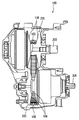
図1を参照して、本発明の実施の形態に係る疲労試験装置で疲労強度が試験されるリングおよびエレメントにより構成される無端金属ベルトが用いられるベルト式無段変速機100について説明する。このベルト式無段変速機100においては、無端金属ベルト106が、入力軸200に取付けられた入力側プーリ220および出力軸300に取付けられた出力側プーリ320に巻き掛けられて使用される。
With reference to FIG. 1, a belt type continuously
入力側プーリ220および出力側プーリ320は、溝幅を無段階に変えられる1対のシーブ108をそれぞれ備え、車両の走行状態に応じて制御される油圧回路により溝幅を変えることで、無端金属ベルト106の入力側プーリ220および出力側プーリ320に対する巻付け半径が変わり、これにより入力軸200と出力軸300との間の回転数比、すなわち変速比を連続的に無段階に変化させることができる。
The input-
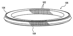
図2を参照して、無端金属ベルト106は、多数のエレメント102が互いに板厚方向に環状に並べて配置され、その左右のサドル部に環状の金属帯であるリング104を通して各エレメント102が結束されて、図3に示すように、全体として、無端金属ベルト106が構成される。
Referring to FIG. 2,
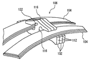
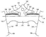
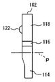
エレメント102の形状の一例を、図4および図5に示す。エレメント102の幅方向の両側の側面は、シーブ108におけるテーパ状のシーブ面110に接触する対シーブ摩擦面112であって、シーブ面110と一致するテーパ面とされている。その対シーブ摩擦面112を備えた基体部分114の幅方向での中心部に、図4での上側に延びた首部116が形成され、その首部116が、左右に広がった頂部118につながっている。その左右に広がった頂部118と基体部分114との間にスリットが形成されており、この左右2つのスリットの部分にリング104が通されている。そして、基体部分114におけるリング104が接触する面がサドル面120となっている。
An example of the shape of the
このサドル面120の高さは、基体部分114を横切るピッチ線Pからの寸法で表わされる。また、エレメント102の幅は、ピッチ線P上の寸法で表わされる。なお、頂部118のうち首部116の延長位置には、一方の面側に凸となり、他方の面側では凹となったディンプル・ホール122が形成されており、互いに隣接するエレメント102のディンプル・ホール122が互いに嵌合するようになっている。なお、ディンプル・ホール122の凸部を有する面がエレメントの表面、凹部を有する面がエレメントの裏面である。
The height of the
図4に示すように、サドル面120にはクラウニングRが付与され、上に凸の曲面形状を有する。この曲面形状に沿ってリング104が当接している。また、首部116とサドル面120との間には窪み123が形成されている。この窪み123は、単一の曲率半径(たとえばR=0.5mm)で形成されていたり、互いに異なる曲率を有する複数の部分が組合されて形成されていたりする。この窪み123があることにより、リング104の首部116への乗り上げを防止できるとともに、エレメント102における応力集中を避けることができる。
As shown in FIG. 4, the
無端金属ベルト106は、1対のシーブ108の間に挟み付けられて使用される。その場合、シーブ面110および対シーブ摩擦面112がテーパ面であるために、各エレメント102には、シーブ108による挟圧力により半径方向での外側に荷重が作用するが、各エレメント102がリング104によって結束されているので、リング104の張力により半径方向での外側への移動が規制される。その結果、シーブ面110と対シーブ摩擦面112との間に摩擦力が生じ、あるいは油膜の剪断力が生じてシーブ108と無端金属ベルト106との間でトルクが伝達される。
The
リング104は、より詳しくは、図2および図4に示すように、9〜12層に積層された状態で各エレメント102を結束している(ただし、図2および図4では9〜12層ではなく3層として表わしている)。この場合、下層のリング104ほど周長が短く、上層のリングほど周長が長くされる。
More specifically, as shown in FIGS. 2 and 4, the
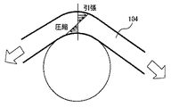
リング104に発生する応力について説明する。前述したように無段変速機に組み込まれた無端金属ベルト106を構成するリング104には、引張り応力と曲げ応力とが作用する。引張り応力は、入力側プーリ220および出力側プーリ320によりリング104に張力が付与されることにより、リング104に発生する。曲げ応力は、入力側プーリ220および出力側プーリ320によりリング104が回転されることにより、リング104に繰返し発生する。図6に示すように、回転体であるローラによりリング104が回転されると、リング104に繰返し曲げ応力が発生する。無段変速機におけるリング104は、このような応力が繰返し発生している状態で使用される。そのため、このような応力の発生による疲労試験を行なう必要がある。
The stress generated in the
リング104単体で疲労試験を行なう場合に、通常の円筒にクラウニングRと窪み123とを付与した形状の複数のローラにリング104を巻き掛けて軸間力を設定して、ローラを回転させて疲労試験を行なった場合、非常に長い時間を必要とする。すなわち、実際のエレメントを同等のクラウニングRおよび窪み123を用いるので、実際にリング104が破断するまで疲労試験を行なうと非常に長い時間を必要とする。本実施の形態に係る疲労試験装置は、リング104単体での疲労試験において、窪み123とは異なる形状を有するローラを用いて、疲労試験に必要な時間を短くする。
When the fatigue test is performed on the
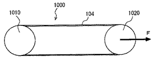
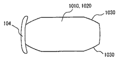
図7および図8を参照して、本実施の形態に係る疲労試験装置1000について説明する。疲労試験装置1000は、2つのローラにリング104を巻き掛けて、所定時間またはリング104が疲労破壊するまでの時間、ローラを回転させるものである。疲労試験装置1000は、耐疲労試験対象のリング104が巻き掛けられ、リング104を予め定められた速度および張力で回転させる第1ローラ1010および第2ローラ1020を含む。第1ローラ1010および第2ローラ1020には、それらのそれぞれの中央部にのみクラウニングRが付与されている。第1ローラ1010は、回転力を発生させるモータ等の駆動機構より回転される。このとき、制御装置により予め定められた回転数になるように制御される。
A
第2ローラ1020は、第1ローラ1010の回転力により回転する従動ローラである。この第2ローラ1020は、第1ローラ1010から離れる方向に移動される。これにより、第1ローラ1010および第2ローラ1020の間に軸間力が付与され、リング104に張力が付与される。この第2ローラ1020の移動により付与される軸間力は、リング104を構成要素とする無端金属ベルトを無段変速機に組み込んだ場合の、リング104の張力を模擬するように調節される。
The
第1ローラ1010および第2ローラ1020にリング104が巻き掛けられて、これらのローラが回転することにより、図6に示すように繰返し曲げ応力が発生する。疲労試験装置1000において発生する曲げ応力は、リング104を構成要素とする無端金属ベルトを無段変速機に組み込んだ場合に、リング104に発生する曲げ応力を模擬できるように、第1ローラ1010および第2ローラ1020の径が決定される。
When the
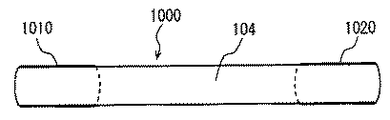
第1ローラ1010および第2ローラ1020は、図9に示すように、その四隅に大きな溝部とも言うべきローラ端部1030が形成されている。このローラ端部1030の形状は、リング104のエレメント102の窪み123に対する比率よりも大きい比率になるように設計されている。このようなローラ端部1030を有する第1ローラ1010および第2ローラ1020を用いることにより、エレメントのサドル部にベルトが接触する実際の使用状態に対して、ローラ1010,1020にはリング104の中央部しか接触しない状態になる。図9に示すように、リング104が巻き掛かっているローラ1010,1020の幅は、実際に巻き掛かっている幅(図4参照)よりも小さくなる。このため、ローラ1010,1020に巻き掛かっているリング104端部においては引張り応力が作用しにくくなり、端部の応力が低く抑制される。
As shown in FIG. 9, the
これは、リング104の端部における引張り応力の抜けが大きくなることを示す。これにより、リング104の中央部とリング104の端部との応力振幅が大きくなる。これは、実際のエレメント102の状態と同じ状態では、リング104の破断までに長い時間を必要とするが、このように応力振幅を大きくした状態で疲労状態を試験するので、短時間でリング104単体の疲労試験を終えることができることを示す。なお、図10に従来の第1ローラ1010および第2ローラ1020を示す。
This indicates that the release of tensile stress at the end of the
以上のような構造を有する疲労試験装置1000を用いた疲労試験方法について説明する。
A fatigue test method using the
疲労評価対象のリング104を選定して、第1ローラ1010および第2ローラ1020に巻き掛ける。第2ローラ1020を第1ローラから離れる方向に予め定められた軸間力になるまで移動させてリング104に所定の引張り応力を与える。この引張り応力は、無段変速機におけるリング104に発生する引張り応力を模擬するものである。
The
第1ローラ1010を予め定められた回転数で回転させると、従動ローラである第2ローラ1020も回転して、リング104が回転する。
When the
このような第1ローラ1010と第2ローラ1020とにより、所定の回転数と所定の引張り応力とでリング104を回転させると、リング104に繰返し曲げ応力が発生する。このときリング104は、図9に示す第1ローラ1010および第2ローラ1020により回転されているので、そのリング104において発生する応力振幅が大きくなる。したがって、本実施の形態に係る疲労試験装置1000におけるリング104単体の疲労試験において、リング104の疲労状態を短時間で判定することができる。
When the
所定時間このような状態を維持した後、リング104が疲労破壊しなければ、そのリング104は良品と判断される。一方、所定時間の間に、リング104が疲労起点から発生したクラック等が成長して疲労破壊すれば、そのリング104は不良品と判断される。また、リング104が疲労破壊するまでこのような状態を維持するようにしても、従来よりも短時間で疲労破壊することになる。
After such a state is maintained for a predetermined time, if the
以上のようにして、本実施の形態に係る疲労試験装置を用いた試験方法によると、リングに対するエレメントの窪みの相対的な大きさに関して、疲労試験装置の回転ローラの形状を変更して、リングに対するエレメントの窪みを相対的に大きくした。このため、リング端部にローラが巻き掛からないで、リング端部の引張り応力が抜けて、応力振幅を大きくすることができ、リングの破断までに長い時間を必要としていた従来の試験方法に比べて、短時間でリング単体の疲労試験を終えることができるようになった。 As described above, according to the test method using the fatigue test apparatus according to the present embodiment, the shape of the rotating roller of the fatigue test apparatus is changed with respect to the relative size of the recess of the element with respect to the ring. The recess of the element with respect to was made relatively large. For this reason, the roller does not wrap around the ring end, the tensile stress at the ring end is released, the stress amplitude can be increased, and compared to the conventional test method that required a long time to break the ring. As a result, the fatigue test of the ring itself can be completed in a short time.
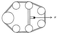
なお、図9および図10で示した本実施の形態に係る疲労試験装置に代えて、図11に示すように複数のローラを用いたものであってもよい。 In place of the fatigue testing apparatus according to the present embodiment shown in FIGS. 9 and 10, a plurality of rollers may be used as shown in FIG.
今回開示された実施の形態はすべての点で例示であって制限的なものではないと考えられるべきである。本発明の範囲は上記した説明ではなくて特許請求の範囲によって示され、特許請求の範囲と均等の意味および範囲内でのすべての変更が含まれることが意図される。 The embodiment disclosed this time should be considered as illustrative in all points and not restrictive. The scope of the present invention is defined by the terms of the claims, rather than the description above, and is intended to include any modifications within the scope and meaning equivalent to the terms of the claims.
100 無段変速機、102 エレメント、104 リング、106 無端金属ベルト、108 シーブ、110 シーブ面、112 対シーブ摩擦面、114 基体部分、116 首部、118 頂部、120 サドル面、122 ディンプル・ホール、124 傾斜面、200 入力軸、220 入力側プーリ、300 出力軸、320 出力側プーリ、1000 疲労試験装置、1010 第1ローラ、1020 第2ローラ、1030 ローラ端部。 100 continuously variable transmission, 102 element, 104 ring, 106 endless metal belt, 108 sheave, 110 sheave surface, 112 to sheave friction surface, 114 base portion, 116 neck, 118 top, 120 saddle surface, 122 dimple hole, 124 Inclined surface, 200 input shaft, 220 input side pulley, 300 output shaft, 320 output side pulley, 1000 fatigue test apparatus, 1010 first roller, 1020 second roller, 1030 roller end.
Claims (6)
前記リングが掛けられるとともに軸間力が付与される複数のローラと、
前記複数のローラの中の少なくとも1つのローラを回転させるための回転手段とを含み、
前記複数のローラは、前記リング端面に対する前記窪みの比率よりも大きな比率の模擬窪みを有する、無端金属ベルト用リングの疲労試験装置。 A plurality of elements each including a saddle portion, a top portion, and a neck portion connecting the saddle portion and a recess between the saddle portion and the neck portion are arranged in the plate thickness direction, and between the saddle portion and the top portion of the element. A fatigue test apparatus applied to the ring in an endless metal belt constructed by passing an annular ring through the ring,
A plurality of rollers on which the ring is applied and an interaxial force is applied;
Rotating means for rotating at least one of the plurality of rollers,
The plurality of rollers is a fatigue test apparatus for an endless metal belt ring, wherein the plurality of rollers have simulated depressions having a larger ratio than the ratio of the depressions to the ring end surface.
前記リングを、前記リング端面に対する前記窪みの比率よりも大きな比率の模擬窪みを有する複数のローラに掛けるステップと、
前記ローラに軸間力を付与することにより、前記リングに引張り応力を付与する引張りステップと、
前記複数のローラの少なくとも1つのローラを回転させることにより、前記リングに繰返し曲げ応力を付与する曲げステップとを含む、無端金属ベルト用リングの疲労試験方法。 A plurality of elements each including a saddle portion, a top portion, and a neck portion connecting the saddle portion and a recess between the saddle portion and the neck portion are arranged in the plate thickness direction, and between the saddle portion and the top portion of the element. A fatigue test method applied to the ring in an endless metal belt constructed by passing an annular ring through the ring,
Hanging the ring over a plurality of rollers having simulated depressions in a ratio greater than the ratio of the depressions to the ring end face;
A tensioning step for imparting a tensile stress to the ring by applying an interaxial force to the roller;
And a bending step of repeatedly applying bending stress to the ring by rotating at least one of the plurality of rollers.
Priority Applications (1)
| Application Number | Priority Date | Filing Date | Title |
|---|---|---|---|
| JP2004109066A JP4161928B2 (en) | 2004-04-01 | 2004-04-01 | Endless metal belt ring fatigue testing apparatus and fatigue testing method |
Applications Claiming Priority (1)
| Application Number | Priority Date | Filing Date | Title |
|---|---|---|---|
| JP2004109066A JP4161928B2 (en) | 2004-04-01 | 2004-04-01 | Endless metal belt ring fatigue testing apparatus and fatigue testing method |
Publications (2)
| Publication Number | Publication Date |
|---|---|
| JP2005291995A true JP2005291995A (en) | 2005-10-20 |
| JP4161928B2 JP4161928B2 (en) | 2008-10-08 |
Family
ID=35325079
Family Applications (1)
| Application Number | Title | Priority Date | Filing Date |
|---|---|---|---|
| JP2004109066A Expired - Fee Related JP4161928B2 (en) | 2004-04-01 | 2004-04-01 | Endless metal belt ring fatigue testing apparatus and fatigue testing method |
Country Status (1)
| Country | Link |
|---|---|
| JP (1) | JP4161928B2 (en) |
Cited By (2)
| Publication number | Priority date | Publication date | Assignee | Title |
|---|---|---|---|---|
| CN108287113A (en) * | 2018-02-09 | 2018-07-17 | 西南交通大学 | A kind of testing equipment for ring component in slope protection structure |
| CN114729864A (en) * | 2020-06-23 | 2022-07-08 | 株式会社Lg新能源 | Fatigue testing device for metal foil and method of using the same |
-
2004
- 2004-04-01 JP JP2004109066A patent/JP4161928B2/en not_active Expired - Fee Related
Cited By (5)
| Publication number | Priority date | Publication date | Assignee | Title |
|---|---|---|---|---|
| CN108287113A (en) * | 2018-02-09 | 2018-07-17 | 西南交通大学 | A kind of testing equipment for ring component in slope protection structure |
| CN108287113B (en) * | 2018-02-09 | 2024-06-04 | 西南交通大学 | Test equipment for ring member in slope protection structure |
| CN114729864A (en) * | 2020-06-23 | 2022-07-08 | 株式会社Lg新能源 | Fatigue testing device for metal foil and method of using the same |
| US12292418B2 (en) | 2020-06-23 | 2025-05-06 | Lg Energy Solution, Ltd. | Fatigue testing apparatus for metallic foil and method using same |
| CN114729864B (en) * | 2020-06-23 | 2026-04-10 | 株式会社Lg新能源 | Fatigue testing equipment for metal foil and method of using said fatigue testing equipment |
Also Published As
| Publication number | Publication date |
|---|---|
| JP4161928B2 (en) | 2008-10-08 |
Similar Documents
| Publication | Publication Date | Title |
|---|---|---|
| US20070191157A1 (en) | Method of pretensioning power transmission chain,device for said method and power transmission apparatus | |
| US8863368B2 (en) | Winding member manufacturing method, winding member manufacturing apparatus, winding member peripheral length measuring apparatus and pre-tension applying apparatus | |
| JP5347290B2 (en) | Power transmission chain pretension method | |
| JP4161928B2 (en) | Endless metal belt ring fatigue testing apparatus and fatigue testing method | |
| JP4898107B2 (en) | Manufacturing method of power transmission chain | |
| JP3912291B2 (en) | Endless metal belt ring fatigue testing apparatus and fatigue testing method | |
| JP2009115591A (en) | Power transmission chain inspection method and inspection device | |
| JP4770454B2 (en) | Method for manufacturing power transmission chain for continuously variable transmission | |
| JP4292807B2 (en) | Wear resistance evaluation method for endless metal belt ring | |
| JP2007270942A (en) | Power transmission chain and power transmission device | |
| JP5035514B2 (en) | Power transmission chain manufacturing method and manufacturing apparatus | |
| JP2009028737A (en) | Power transmission chain pretension method and pretension device | |
| JP4853017B2 (en) | Power transmission chain, method of manufacturing the same, and power transmission device | |
| JP4893561B2 (en) | Power transmission chain and power transmission device | |
| JP2008111494A (en) | Power transmission chain manufacturing method and manufacturing apparatus | |
| JP2009255121A (en) | Pre-tensioning method and apparatus for power transmission chain | |
| JP4770610B2 (en) | Power transmission chain and power transmission device | |
| JP2008168301A (en) | Power transmission chain manufacturing method and manufacturing apparatus | |
| JP2008144824A (en) | Power transmission chain manufacturing method and manufacturing apparatus | |
| JP5151140B2 (en) | Power transmission chain and power transmission device | |
| JP4821392B2 (en) | Power transmission chain design method, power transmission chain, and power transmission device | |
| JP2008238226A (en) | Power transmission chain pretension method and pretension jig | |
| JP2008267577A (en) | Power transmission chain pretension method and pretension device | |
| JP2011200874A (en) | Method for manufacturing power transmission chain | |
| JP2008138768A (en) | Stress applying method for power transmission chain and stress applying device used for the method |
Legal Events
| Date | Code | Title | Description |
|---|---|---|---|
| A621 | Written request for application examination |
Free format text: JAPANESE INTERMEDIATE CODE: A621 Effective date: 20060823 |
|
| A977 | Report on retrieval |
Free format text: JAPANESE INTERMEDIATE CODE: A971007 Effective date: 20080204 |
|
| A131 | Notification of reasons for refusal |
Free format text: JAPANESE INTERMEDIATE CODE: A131 Effective date: 20080212 |
|
| A521 | Written amendment |
Free format text: JAPANESE INTERMEDIATE CODE: A523 Effective date: 20080407 |
|
| A131 | Notification of reasons for refusal |
Free format text: JAPANESE INTERMEDIATE CODE: A131 Effective date: 20080507 |
|
| A521 | Written amendment |
Free format text: JAPANESE INTERMEDIATE CODE: A523 Effective date: 20080603 |
|
| TRDD | Decision of grant or rejection written | ||
| A01 | Written decision to grant a patent or to grant a registration (utility model) |
Free format text: JAPANESE INTERMEDIATE CODE: A01 Effective date: 20080701 |
|
| A01 | Written decision to grant a patent or to grant a registration (utility model) |
Free format text: JAPANESE INTERMEDIATE CODE: A01 |
|
| A61 | First payment of annual fees (during grant procedure) |
Free format text: JAPANESE INTERMEDIATE CODE: A61 Effective date: 20080714 |
|
| FPAY | Renewal fee payment (event date is renewal date of database) |
Free format text: PAYMENT UNTIL: 20110801 Year of fee payment: 3 |
|
| R151 | Written notification of patent or utility model registration |
Ref document number: 4161928 Country of ref document: JP Free format text: JAPANESE INTERMEDIATE CODE: R151 |
|
| FPAY | Renewal fee payment (event date is renewal date of database) |
Free format text: PAYMENT UNTIL: 20110801 Year of fee payment: 3 |
|
| FPAY | Renewal fee payment (event date is renewal date of database) |
Free format text: PAYMENT UNTIL: 20110801 Year of fee payment: 3 |
|
| FPAY | Renewal fee payment (event date is renewal date of database) |
Free format text: PAYMENT UNTIL: 20120801 Year of fee payment: 4 |
|
| FPAY | Renewal fee payment (event date is renewal date of database) |
Free format text: PAYMENT UNTIL: 20130801 Year of fee payment: 5 |
|
| LAPS | Cancellation because of no payment of annual fees |