JP2004535071A - Method for removing contaminants from flat media carrier, flat media carrier cleaning device, media carrier cleaning device, and box cleaning system - Google Patents
Method for removing contaminants from flat media carrier, flat media carrier cleaning device, media carrier cleaning device, and box cleaning system Download PDFInfo
- Publication number
- JP2004535071A JP2004535071A JP2003511982A JP2003511982A JP2004535071A JP 2004535071 A JP2004535071 A JP 2004535071A JP 2003511982 A JP2003511982 A JP 2003511982A JP 2003511982 A JP2003511982 A JP 2003511982A JP 2004535071 A JP2004535071 A JP 2004535071A
- Authority
- JP
- Japan
- Prior art keywords
- surfactant
- rotor
- water
- box
- door
- Prior art date
- Legal status (The legal status is an assumption and is not a legal conclusion. Google has not performed a legal analysis and makes no representation as to the accuracy of the status listed.)
- Pending
Links
Images


Classifications
-
- H—ELECTRICITY
- H01—ELECTRIC ELEMENTS
- H01L—SEMICONDUCTOR DEVICES NOT COVERED BY CLASS H10
- H01L21/00—Processes or apparatus adapted for the manufacture or treatment of semiconductor or solid state devices or of parts thereof
- H01L21/67—Apparatus specially adapted for handling semiconductor or electric solid state devices during manufacture or treatment thereof; Apparatus specially adapted for handling wafers during manufacture or treatment of semiconductor or electric solid state devices or components ; Apparatus not specifically provided for elsewhere
- H01L21/67005—Apparatus not specifically provided for elsewhere
- H01L21/67011—Apparatus for manufacture or treatment
- H01L21/67017—Apparatus for fluid treatment
- H01L21/67028—Apparatus for fluid treatment for cleaning followed by drying, rinsing, stripping, blasting or the like
- H01L21/6704—Apparatus for fluid treatment for cleaning followed by drying, rinsing, stripping, blasting or the like for wet cleaning or washing
-
- B—PERFORMING OPERATIONS; TRANSPORTING
- B08—CLEANING
- B08B—CLEANING IN GENERAL; PREVENTION OF FOULING IN GENERAL
- B08B3/00—Cleaning by methods involving the use or presence of liquid or steam
- B08B3/02—Cleaning by the force of jets or sprays
Abstract
フラットメディアキャリア(52)またはボックス(52)などの容器(52)を洗浄する機械(10)は、チャンバ(24)内の回転ローター(70)上に支えられたコンテナ(52)上へ、洗浄液をスプレーするよう配置された、ノズルの内側アレイおよび外側アレイ(R1‐R8)を備えている。水と洗剤または界面活性剤との混合剤である洗浄液は、定量ポンプ(48、49)を用いて界面活性剤格納容器(35)から、界面活性剤を直接引き出すことにより調合される。水の流速は流量計(116、118)によって測定され、汚染物質を取り除く所望の界面活性剤濃度の混合剤を生成するため、定量ポンプ(48、49)と組み合わせて、適切な量の界面活性剤が、水路(140)内へ注入される。ローター(70)上のボックスホルダアセンブリ(250a‐250d)は、ボックス(52)をローター(70)に固定する上下のフック(322、324)を含んでいる。また、ローター(70)上には、ボックスドアホルダアセンブリ(206a、206b)が設けられる。A machine (10) for cleaning containers (52), such as a flat media carrier (52) or a box (52), places the cleaning liquid on a container (52) supported on a rotating rotor (70) in a chamber (24). An inner array and an outer array (R1-R8) of nozzles arranged to spray. The cleaning liquid, which is a mixture of water and a detergent or a surfactant, is prepared by directly drawing out the surfactant from the surfactant storage container (35) using a metering pump (48, 49). The flow rate of the water is measured by flow meters (116, 118) and combined with a metering pump (48, 49) to produce an appropriate amount of surfactant to produce a mixture of the desired surfactant concentration to remove contaminants. The agent is injected into the channel (140). The box holder assemblies (250a-250d) on the rotor (70) include upper and lower hooks (322, 324) that secure the box (52) to the rotor (70). The box door holder assemblies (206a, 206b) are provided on the rotor (70).
Description
【技術分野】
【0001】
本発明の分野は、半導体ウエハ、基板、フラットパネルディスプレイ、および他のフラットメディアを保持し、および処理するために用いられる、濯ぎ用および乾燥用コンテナおよびキャリアのための洗浄装置に関連している。
【背景技術】
【0002】
シリコンまたは他の半導体ウエハ、基板、フォトマスク、フラットパネルディスプレイ、データディスクおよび同様の製品などのフラットメディアは、汚染レベルを非常に低くする必要がある。微小な汚染物質さえ欠陥を引き起こしかねない。従って、こうしたタイプのフラットメディアの生産のすべてのステージ、またはほとんどすべてのステージにおいて、高レベルの清浄度が維持される必要がある。「ウエハ」はあらゆる形式のフラットメディアを意味すると理解される場合もあるが、説明されるフラットメディアを、以下「ウエハ」と称する。
【0003】
ウエハは、通常バッチで処理される。シリコンウエハは、例えば、コンピュータ、電話、テレビ、および他の電子製品で用いられる半導体チップの製造において、酸化、フォトリソグラフィ、拡散、化学蒸着、金属化、およびエッチングなど、多くのバッチ処理ステップを受けることになる。バッチの取り扱いは、全生産プロセス、または1つ以上の処理ステップまたは関連した取り扱い動作について行われる場合がある。このタイプのバッチ処理では、処理されるウエハを保持するのに、ほとんど常に、何らかのタイプのキャリアまたは容器を利用している。
【0004】
ウエハキャリア、ウエハボックス、ウエハカセット、ウエハボート、またはウエハ容器は、一群のウエハを保持する。製造プロセスの特定ステージでは、ウエハキャリアが洗浄されなければならない。通常それらには、スロット、溝または開口部、および汚染物質を補足可能な内側コーナーを含む特徴があるので、それらの洗浄は困難である。ウエハ処理のために要求される非常に低い汚染レベルにより、洗浄における困難さは強調されている。
【0005】
従って、ウエハキャリアの洗浄は、困難で、時間がかかり、比較的高価な手順のままである。裏面に接着剤が付いたラベル、指紋、ほこり、金属粒子、フォトレジスト、および有機化合物も、ウエハキャリアを汚染することがある。
【0006】
様々な機械が製造され、ウエハキャリアの洗浄に用いられてきた。これらの機械では、キャリアはローターに取り付けられ、キャリア上に洗浄液がスプレーされる一方で、キャリアはチャンバ内で回転する。この回転運動は、処理時間を最小にし、さらにキャリアの乾燥を補助する。特定のアプリケーションでは、洗剤または界面活性剤が導入され、脱イオン水と混合される。こうした使用では、界面活性剤は、緩く付着した粒子を取り除くのを補助する湿潤剤として作用し、その一方で洗剤が汚染物質と化学的に反応して、それらを洗浄して分離させるよう作用する。界面活性剤は、通常、一度だけ使用され、廃棄物として捨てられる。洗剤は、濃縮された場合、再生されてもよい。
【0007】
界面活性剤または洗剤は、通常、容器またはタンク内に保持される。界面活性剤または洗剤の流れは、必要な濃度レベルを生成するよう、僅かな流量で適用されるので、キャリアへの界面活性剤または洗剤の体積流量の制御は、困難なものになりかねない。以前は、界面活性剤は、大量格納容器から、必要なレベルまで希釈する保持タンク内へポンプで送られていた。希釈された界面活性剤溶液は、その後、ベンチュリ管により、保持タンクから、水に混合され、または吸引される、水流内へ引き出される。水と界面活性剤との混合剤は、その後、ウエハキャリアへの注入準備が出来た、濯ぎ多岐管に向けられる。
【発明の開示】
【発明が解決しようとする課題】
【0008】
従って、本発明の目的は、フラットメディア用のキャリアおよび容器を洗浄する、改良された機械を提供することである。
【0009】
キャリア、またはボックスおよびそれらのドアの、ローターへのローディング、またはローターからのアンローディングを容易にし、ローターを様々な条件のもとでバランス良く維持することは、工学上の難問として残っている。従って、本発明の目的はまた、改良されたローターを提供することである。
【課題を解決するための手段】
【0010】
本発明は、チャンバ内に、回転可能な形で取り付けられたローターを含む、フラットメディアキャリアの洗浄装置についてのものである。チャンバ内のノズルは、ローター上に支えられたキャリアに、水と洗剤または界面活性剤との洗浄混合剤をスプレーするよう配置される。洗浄混合剤は、定量ポンプを用いて、界面活性剤大量格納容器から界面活性剤を直接引き出すことにより調合される。水の流速は流量計によって測定され、定量ポンプと組み合わせて、適切な量の界面活性剤が、汚染物質を取り除く所望の界面活性剤濃度で混合剤を生成するために、水路内へ注入される。
【0011】
本発明の第2の態様では、界面活性剤または洗剤溶液は、ウエハキャリア内へ注入される前に、水と界面活性剤が完全に混合されるよう、インライン混合制御バルブにおいて、またはその上流で、水路に注入される。
【0012】
本発明の第3の態様では、ウエハキャリアには、キャリアにスプレーする複数の濯ぎ多岐管が設けられ、各多岐管に対するインレット水路には、流量計が設けられ、さらに、各水路には、所望の界面活性剤濃度の混合剤を作り出すために、各水路に適切量の界面活性剤を注入し得るよう、界面活性剤注入用の別々の定量ポンプが設けられている。
【0013】
第4の態様では、ウエハの取り扱いに用いられるキャリアの洗浄システムは、閉鎖容器内にローターを有するボックス洗浄装置を含んでいる。ローター上のボックスホルダアセンブリは、ボックスをローターに固定する上下のフックを含んでいる。また、ローター上には、ボックスドアホルダアセンブリが設けられる。ボックスドアホルダアセンブリは、多数のボックスドア保持位置を有しているのが好ましい。各ボックスドア保持位置には、ドアを保持するドアガイドおよびドアフックが備えられているのが有利である。ボックスドアホルダアセンブリにより、ドアを別々に洗浄する必要が回避され、ボックスおよびそれらのドアの双方が遠心クリーナーを用いて洗浄可能となる。
【0014】
第5および別々の態様では、ローターには、ローターの周りに対称的に離された偶数のボックスホルダアセンブリ、およびローターの周りに対称的に離された偶数のドアホルダアセンブリが設けられている。これにより、ローターが釣り合いのとれていない状態となることを回避可能となる。
【0015】
第6の態様では、スプレー多岐管は、真直ぐなスプレーノズル、および曲がったスプレーノズルを有している。真直ぐなスプレーノズルは、スプレーを、ローターのセンターおよび直接ボックス内に供給する。回転方向へ、および/または、回転方向から離れるように方向付けられた、曲がったスプレーノズルは、リーディング、および/または、トレーリング表面、コーナー、およびボックスの機構にスプレーするよう位置決めされるほうが良い。これは、改良された洗浄をもたらす。
【0016】
また、スプレー多岐管は、上向きおよび/または下向きの角度に方向付けられた、曲がったスプレーノズルを有していてもよい。
【0017】
他の、および、さらなる目的、発明的特徴、および利点は、以下において示される。本発明には、上述した特徴の、副次的な組み合せも存在している。
【発明を実施するための最良の形態】
【0018】
ここで図面の詳細に戻ると、図1および図2は、密閉容器を形作る、フレーム12およびハウジングパネル14を有する、キャリア洗浄機械10を図示している。バックドア16およびフロントドア16Aは、機械10の前面および背面に設けられている。概して、機械10は、半導体製造に用いられるタイプの、クリーンルームにインストールされる。エアフィルタ密閉容器18は、フロントドア16Aの上方に位置し、クリーンルームの空気を濾過するフィルタを含んでいる。排気ダクト26は、背面右隅で、機械10上部から延びており、通常、施設またはビルの排気ダクトに接続されている。
【0019】
図3、図6および図9を参照すると、筒状チャンバ24は、フレーム12内に支えられている。チャンバ24は、筒状の側壁25を有しており、上部プレート36および底板38により、天地で密閉されている。上部プレート36は、中央開口部37を有しており、これにより、フィルタボックス18を通り抜ける空気は、チャンバ24を通って下向きに流れ込むことになる。チャンバ24の背後下部および右側部の排気プレナム50は、チャンバ24の外へ空気を動かすよう、排気ダクト26に接続されている。排気プレナム50内の、チャンバ24の底部にある排出開口部39は、チャンバから流体を排出する。
【0020】
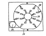
図5、図9、および図13を参照すると、各々が例えば12個のスプレーノズルを有している、外部濯ぎ多岐管28(R1‐R4)は、チャンバ筒状側壁25上の、チャンバ24の外周の周りに位置決めされる。外部濯ぎ多岐管28は、外部濯ぎ多岐管28の濯ぎスプレーノズル30が、ワークピース、すなわちウエハキャリアにプレーをするよう、適切に位置決めされる限り、図4から図6および図10A、Bに示されるように筒状側壁25の外側、または、筒状の側壁25の内側面上にあってもよい。
【0021】
内部濯ぎ多岐管29は、ワークピース(すなわち、ウエハキャリア、容器または蓋)上に外向きにスプレーするよう方向づけられた、多数の濯ぎスプレーノズル30を有する各内部濯ぎ多岐管(R5-R8)を伴って、チャンバ24の中心近傍に位置決めされる。
【0022】
同様に、各々が多数の乾燥スプレーノズル66を有する、外部乾燥多岐管64(D5-D8)は、チャンバの筒状側壁25上の、チャンバ24の円周の周りで離されている。また、各々が多数の乾燥スプレーノズル66を有する、内部乾燥多岐管65(D1‐D4)は、チャンバ24の中心近傍に位置決めされる。乾燥多岐管(D1‐D8)および濯ぎ多岐管(R1‐R8)の好適な方向付けは、図13に示されている。
【0023】
暫時図10A、Bを参照すると、外部乾燥多岐管64は、分配多岐管61を経由し、その後流体経路63により、制御バルブ63aを経由して空気または窒素などの加圧ガスのサプライ120に接続されている。同様に、内部乾燥多岐管65は、分配多岐管68を経由し、その後流体経路67により、制御バルブ67aを経由して加圧ガスのサプライ130に接続されている。外部濯ぎ多岐管28は、分配多岐管141を経由し、その後流体経路140により、制御バルブ170および脱イオン (DI)水源110に接続されている。内部濯ぎ多岐管29は、分配多岐管151を経由し、その後流体経路150により、制御バルブ180およびDI‐水源110に接続されている。加圧ガス経路もまた、浄化のために制御バルブ170、180を経由して、スプレー多岐管に接続されている。昇圧ポンプ46は、外部水源110から濯ぎ多岐管28、29までのDI水の水圧を増加させる。
【0024】
制御バルブ170、180は、界面活性剤がDI水に完全に混合されるようにする、混合制御バルブであることが好ましい。
【0025】
図3から図6および図10A、Bから図12を参照すると、界面活性剤タンクまたはボトル35は、流体経路190を経由して、界面活性剤定量ポンプ48、49に接続されている。界面活性剤定量ポンプ48は、流体経路192を経由して、混合制御バルブ170に接続されている。ポンプ48は、タンクまたはボトル35からの界面活性剤を、制御バルブ170に送り込み、そこでそれは、流体経路140を経由して外部濯ぎ多岐管28への注入のためDI水と混合される。界面活性剤定量ポンプ49は、流体経路194を経由して、制御バルブ180に接続されている。ポンプ49は、タンクまたはボトル35からの界面活性剤を、制御混合バルブ180に送り込み、そこでそれは、流体経路150を経由して外部濯ぎ多岐管29への注入のためDI水と混合される。
【0026】
チャンバ24の底部の排水開口部39は、排水開口部39を、回収タンク42または施設廃棄物排水管92のいずれかに接続する、ダイバータ90へ通じている。
【0027】
界面活性剤側には、混合制御バルブ170の近くにある、流体経路192からの戻り経路142が、(制御バルブ145の制御下で)界面活性剤を容器35へと還流するために設けられ;そして、混合制御バルブ180の近くにある、流体経路194からの戻り経路152は、(制御バルブ155の制御下で)界面活性剤を容器35へと還流するために設けられる。DI水側で、混合制御バルブ170の近くにある、流体経路115からの再循環経路147は、DI水の再循環を提供し;および、混合制御バルブ180の近くにある、流体経路117からの再循環経路157は、DI水の再循環を提供する。再循環経路147、157は、ツールが、経路およびバルブ内でのバクテリアの生成を回避するためにアイドル状態となっている場合でも、ツールを通る水流を提供する。
【0028】
暫時図9を参照すると、エアフィルタボックス18の背後およびセンター上、またはチャンバ24上部に通じるインレット開口部37のエアインレットプレナム56内に、エアヒータ58が設けられている。また、ブランケットヒーター55も、チャンバ24上部の周りに設けられている。コンピュータ/コントローラ112は、様々なポンプ、バルブ、ヒーター、および流量センサにリンクされ、それらを制御する。
【0029】
図6から図9を参照すると、ローター70は、ベース104上のチャンバ24内で回転可能に支えられている。ローターは、フレーム構造75により接続されたトップリング72およびボトムリング74を有している。ラダー76は、トップリング72およびボトムリング74から放射状に外部に延びた、上下のラダーサポート82により旋回式に支えられている。図9に示されるように、各ラダー76は、容器、またはキャリア85、または容器蓋87を保持するための、多数のコンパートメント78を備えている。ラダー76の構成、およびラダー76上のコンパートメント78の設計は、特定サイズおよびタイプの洗浄されるべきキャリア、容器、および蓋に適合している。ローター70全体は、センターコラム100上、およびセンターコラム100内のローター軸106上に回転可能に支えられている。ロータードライブモーター102は、ローター70を回転させる。ローター70、センターコラム100、およびローター軸106の詳細な設計上の特徴は周知であり、米国特許第5,224,503号明細書において説明されている。代替的に、本ツールは、非回転ラダーで構成されていてもよい。
【0030】
使用に際しては、機械10は、通常、シリコンウエハまたは他のフラットメディアの製造施設にインストールされる。ウエハが様々な処理ステップを通して動かされるにつれて、キャリア85が汚染されることになるため、キャリア内にウエハが置き換えられる前に、洗浄されなければならない。機械10のドア16またはドア16Aが開かれる。ローター70は、ラダー76がドアに並ぶまで、回転され、または割送られる。その後、ラダー76は、ドア16を通って空のコンパートメント78にアクセス可能となるよう、180°回転される。キャリア85は、コンパートメント78にロードされ、ラダーは元の位置に戻り、その結果、コンパートメント78は、チャンバ24の内側に向くことになる。ラダー76は、コンパートメント78がチャンバ24の内側に向き、ラダーを閉鎖位置または動作位置に固定するよう、掛け金または止め金が設けられることが好ましい。その後、(手により、またはロータードライブモーター102の制御を通して)ローター70を回転させることにより、次のラダー76が、ローディングのために、ドアと並ぶ位置にもたらされる。ローディングは、全ラダー76が満たされるまで続く。
【0031】
図6に示されるように、機械10上の施設パネル40は、流体/ガスの流れを測定して、制御するゲージおよびバルブと同様に、脱イオン水、および例えば窒素または空気などのガスを機械10へ入力する接続、および、廃棄物排出管92への接続を有している。
【0032】
界面活性剤タンク35には、例えば、フォトレジストを取り除くのに好適な界面活性剤である、バルトロン(Valtron)DP 94001(高pHアルカリ性洗剤)などの洗剤または界面活性剤が供給される。このアプリケーションで用いられる「界面活性剤」という用語は、界面活性剤または洗剤を意味する。コントローラ112は、バルブおよびポンプの適切な制御を通して、各濯ぎ多岐管28、29へ注入する、所望のDI水/界面活性剤混合剤を作成するために、混合制御バルブ170、180へ、DI水および界面活性剤をもたらす。DI水の昇圧ポンプ46は、DI水を混合制御バルブ170および混合制御バルブ180の双方へ供給するために、供給経路114内の水圧を上げる。流量計116は、供給されるDI水の流量を測定するために、外部濯ぎ混合制御バルブ170の上流の流体経路内に配置される。同様に、流量計118は、供給されるDI水の流量を測定するために、内部濯ぎ混合制御バルブ180の上流の流体経路内に配置される。
【0033】
本システムは、外部濯ぎ多岐管28に注入するDI水/界面活性剤混合剤に対する、合理的に正確な界面活性剤濃度を設定するために、定量ポンプ48の制御と組み合わせて、流量計116からの情報を用いることにより、初期に較正される。同様に、本システムは、内部濯ぎ多岐管29に注入するDI水/界面活性剤混合剤に対する、合理的に正確な界面活性剤濃度を設定するために、定量ポンプ49の制御と組み合わせて、流量計118からの情報を用いることにより、初期に較正される。溶液は、各多岐管に対し、DI水であるバランスで、1:10000の界面活性剤であることが好ましいが、別々のフロー制御/計量を有しており、界面活性剤濃度レベルは個別に設定されてもよい。
【0034】
定量ポンプ48、49は、ダイアフラムポンプなどの、一種の容量型ポンプであることが好ましい。こうしたダイアフラムポンプの流速は、(1ストロークあたりの揚水体積を設定する)ポンプストローク、および/または、(1分あたりのストローク数である)ポンプ速度を調整することにより調整されてもよい。ポンプは、界面活性剤が本システムに、より律動的/間欠的でなく送られるよう、比較的高速度に設定されるのが好ましい。
【0035】
システムオペレーターは、(1ストロークあたりの揚水体積を設定する)ポンプストローク、および/または、(1分あたりのストローク数である)ポンプ速度を調整することにより、界面活性剤/DI水の濃度を調整してもよい。
【0036】
本システムは、定量ポンプ48、49および界面活性剤/DI水の濃度に対する揚水レートを予め設定することにより動作されてもよいが、電子制御システムは、流量計116、118および定量ポンプの揚水レートの電子制御からの入力を用いて実行されてもよい。
【0037】
容器の流体レベルが低く、交換を必要とすることを警告するために、界面活性剤容器35上に低レベルセンサ35aが設けられてもよい。センサ35aは、容器内の液体センサ、または容器の外部に配置された容量センサ、または何らかの他の適当な装置のいずれであってもよい。このセンサは、界面活性剤の交換時期を示すために、レベルが特定の(低)レベルに達する時を判定するだけでもよいし、または、あるタイプのセンサは、界面活性剤レベルに対応する信号を提供してもよい。例えば、容器35が挿入されるトレイ35b(図11参照)は、容器35の重量に、流体レベルの指示を提供するロードセルにより測定されるように、容器の重量変化を伴う容器35の重量を提供するために、界面活性剤容器35を支えるロードセルを含んでいてもよい。
【0038】
コントローラ112は、ロータードライブモーター102を制御し、その結果、ローター70は、例えば1‐50rpmの低速で第1の方向に回転する。ポンプ46、48、49およびバルブ170、180の制御により、DI水/界面活性剤溶液は、回転するローター上のキャリア85にスプレーされる。
【0039】
スプレー適用範囲をより良くするために、例えば3‐10分間の十分な持続時間の後、界面活性剤溶液スプレーを続けながら、ローター70は方向を逆にする。ローター70の内部に位置する内部濯ぎ多岐管29は、チャンバ24の中心から放射状に外側に向かってスプレーする。チャンバの筒状側壁25の周りに位置する外部濯ぎ多岐管28は、チャンバの中心に向かって放射状に内側に向かってスプレーする。ローター70の双方向の回転に結合されるこの二重スプレー動作は容器85のすべての表面の実際には完全な適用範囲を提供する。
【0040】
界面活性剤溶液の適用が終了した後、多岐管は、図10A、Bに示されるように、チェックバルブ143、153および制御バルブ170、180を通って流れるガスまたは窒素により、浄化される。
【0041】
界面活性剤洗浄サイクルの間、ダイバータバルブ90は、流体を施設廃棄物排水管92へ向けるよう位置決めされている。通常、機械10が濯ぎサイクルを始める時、ダイバータ90は、排水開口部39を施設廃棄物排水管92に接続する位置のままである。DI水は、全ての濯ぎ多岐管(R1‐R8)からキャリア85上にスプレーされ、その間、ローター70は、例えば1‐50rpm、好ましくはおよそ6rpmで、第1の方向に回転し、その後、逆に反対方向に回転する。続いて、ヒーター58がオンにされ、ローターは、例えば300rpmまで加速され、それにより、容器85上の水滴が容器から遠心力で振り払われ、容器は乾燥される。ブランケットヒーター55は、チャンバ24の上部外側にあり、チャンバ上部を暖めるために、連続的にオンである。DI濯ぎ水は廃棄物排水管92へと流出する。
【0042】
例えばDI水(界面活性剤を含まない)は、チャンバを通って循環する水循環モードが望まれているなら、ダイバータバルブ90はある位置に切り換えられてもよい。
【0043】
機械10が、様々な汚染物質の洗浄に役立つ一方で、界面活性剤、濯ぎ水、および空気/ガススプレーの継続時間、回転速度およびシーケンス、ヒーター動作、界面活性剤濃度などの、特定の洗浄パラメタは、異なる容器および汚染物質などがある場合、本願明細書の説明から当業者に明らかであるように、最適な結果を得るために、多少変更されてもよい。
【0044】
界面活性剤は、一般に、可燃性または爆発性ではなく、溶剤に関連した同等の環境損失を有してはいない。他方、界面活性剤は非常に高価になり得る。DI水/界面活性剤混合剤に対し、正確で一貫した界面活性剤濃度を実現する定量ポンプを用いて、本システムは界面活性剤を保存する。
【0045】
ここで、図14および図15に示された設計に移ると、ローターアセンブリ236は、ローターフレーム244上に対称的に配置された、偶数個のボックスホルダアセンブリ250a、250b、250c、250dを有している。また、同様に、偶数個のドアホルダアセンブリ260a、260bは、ローターフレーム244上に対称的に配置されている。
【0046】
各ボックスホルダアセンブリ250a‐250dは、同一設計を有しており、他のボックスホルダアセンブリの放射方向の反対側に位置決めされる。特に、ボックスホルダアセンブリ250aは、ボックスホルダアセンブリ250cの放射方向の反対側に位置決めされており;そして、ボックスホルダアセンブリ250bは、ボックスホルダアセンブリ250dの放射方向の反対側に位置決めされている。同様に、ドアホルダアセンブリ260a、260bは、互いに放射方向の反対側に位置決めされている。従って、ローターアセンブリ236は、対称的に、回転のバランスをとる構成で配置された、ボックスホルダアセンブリおよびドアホルダアセンブリを有している。
【0047】
ボックスホルダアセンブリ250a‐250d、およびドアホルダアセンブリ260a、260bは、ローターフレーム244に取り付けられ、ローターアセンブリ236を形成する。ローターフレーム244は、コア構造245に取り付けられる、トップリングプレート246およびボトムリングプレート248を含んでいる。ボックスホルダアセンブリ250a‐250dは、好ましくはボルト275を通して、トップおよびボトムリングプレート246、248に、しっかりと取り付けられる。
【0048】
図16を参照すると、各ドアホルダアセンブリ260a、260bは、トッププレート272、ボトムプレート276、中間プレート274、サイドプレート278、280、およびサイドプレートに取り付けられるアーム292を有している。各ドアホルダアセンブリ260は、好ましくは、ドアホルダアセンブリのトッププレート272とボトムプレート276を貫いて伸びているボルト275を通して、ローターフレーム244のトップおよびボトムリングプレート246、48に、しっかりと取り付けられる。
【0049】
各ドアホルダアセンブリ260a、260bは、概して、中間プレート274により分離された、上部コンパートメント306と下部コンパートメント308とを有している。さらに図16を参照すると、コンパートメント306、308の各々は、ドア325a、325bを保持するよう示されている上部コンパートメント306、およびドア325c、325dを保持するよう示されている下部コンパートメントの、2つのドア保持位置を備えている。ドア保持位置は、互いに鏡像であるのが好ましい。
【0050】
ここで図18および図19も参照すると、各コンパートメント306、308は、底面またはトレイ335、および1対の左側フック322、および1対の右側フック324、およびトッププレート340を有している。図18は、コンパートメント要素の詳細を示している。図19は、底部トレイ335の詳細を示している。ドアスロット336、337は、ドアのボトムエッジを受けるよう、底部トレイ335に設けられる。スロット336、337は、ローターのスピン軸AAに対して半径方向に配置される。スロット336、337は、各々、その放射方向内向きまたは背面終端に、後部斜面338、339を含んでいる。フック322、324の各々は、レッグ325、およびレッグ325に取り付けられたフット327を有している。フック322、324は、互いに鏡像であるのが好ましい。レッグ325は、周囲(すなわち、概してローターの回転経路の接線方向)に延びている。フット327は、ローターの回転軸AAに向かい、放射方向内向きに延びている。ドアは、各ドアホルダにおいて、それらがローターの半径Rに対して、ほとんど並ぶか、または平行となるよう保持されている。図16に示されるように、ドアの広く平坦な側の平面Pは、半径Rに対して、±30、20、または10度以内と成っているのが好ましい。
【0051】
使用に際しては、ドアホルダアセンブリ260へドアをロードするために、密閉容器ドア16(図1に図示)が開けられ、ローターアセンブリは、ドアホルダアセンブリ260aまたは260bが、密閉容器ドア16と並ぶ状態に移動するまで、割送りさせられ、または回転させられる。その後、ドア325a‐dは、ドアホルダアセンブリ260aまたは260bへ、手動でロードされる。
【0052】
コンパートメントへのドア(例えば、ドア325a)のインストール時に、ドア325aの下部は、ドアスロット336内に適合する。ドアスロットは、ドアを横方向に支える(例えば、ドアを横方向の動きに対して保持する)のを補助する。ドア(例えば、ドア325a)は、スロット336を抜け、さらにサイドフック322を抜けている、コンパートメント内の開口部を貫いて、ドアを垂直に挿入することにより、ドアホルダ内にインストールされる。その後、ドアは、スロット336上の所定位置へ横方向に動かされる。ドアの底部は、ドアの底部を、スロット336内へ下向きかつ放射方向外向きに案内する斜面338に係合する。放射方向外向きのドアの縁もまた、サイドフック322と接触する。いったんスロット336内に入ると、ドアは、サイドフック322と係合するまで、放射方向外向きに戻る。その後、ドア325aは、回転するローターにより生じる遠心力による動きに対して、フックにより、適所に確実に位置決めされ、保持される。同様にして、他のドアの各々がロードされる。底部トレイ335上のセンターガイド344は、ドアの内部終端または背部終端を、ドアスロット内に案内するのを補助する。ドア325は、上述の一連のステップの逆を用いることにより、ドアホルダアセンブリ260からアンロードされる。
【0053】
ドア保持位置へロードされると、ドアは、垂直位置、すなわち、ドアの一方の終端がローター軸A-Aの方を向き、ドアの反対側の終端が、ローターから放射方向外向きに向いた位置にある(そして、フックにより係合されている)。ドアの平面または表面は、垂直であり、ローターの移動経路に直交している。1つのドアの平面は、同一コンパートメント306または308内の、隣接したドア平面に面している。ドアは、コンパートメント306または308の側部に保持される。ローディングおよびアンローディングのための空間を許容するために、コンパートメントの中央領域は空になっている。ドアホルダアセンブリ260a、260bは、ボックスホルダアセンブリよりもさらに狭く、ローターアセンブリのより小さなセクターに位置を占めている。
【0054】
上述のシーケンスを用いて、ドアホルダアセンブリ260a、260bには、通常、上部コンパートメント306に2つのドア、さらに、下部コンパートメント308に2つのドアで、ドア325a‐dがロードされる。
【0055】
2つのドアホルダアセンブリ260a、260bは、各々4つのドア、合計8つのドアを担持する。ローターアセンブリ236は、4つのボックスホルダアセンブリ250a‐dを有していて、各アセンブリは2つのボックス、合計8つのボックスを保持する。結果として、洗浄システムの単一サイクルで、8つのボックスおよびボックスドアが洗浄可能である。スピン軸AAの周りに対称となるようロードされるので、ローターアセンブリ236は平衡状態となっている。
【0056】
ここでは、ローターは、4つのボックスホルダアセンブリ、および、各々が(上下)2つのコンパートメントを備えている2つのドアホルダアセンブリを伴って説明されているが、他の部品や構成で作成されたものも使用される。
【0057】
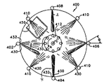
図20を参照すると、改良された遠心ボックスクリーナー実施例400では、外部スプレー多岐管402、404、406、408、410は、流体を、ボックスまたは容器85上および同内部に、放射方向内向きにスプレーする。内部液体スプレー多岐管412は、液体を、ボックスの背面上に、放射方向外向きにスプレーする。内部液体スプレー多岐管412は、回転ローター403内に、放射状に位置決めされている。外部スプレー多岐管402、404、406、408、410は、図20に示されるように密閉容器401内部に配置されたり、または、多岐管のノズルが密閉容器の開口部を通して延びる形で、密閉容器401の外部に位置決めされる。
【0058】
また、内部および外部液体スプレー多岐管は、乾燥サイクルの間、清浄な乾燥空気などのガスをボックスクリーナー400内にスプレーするよう設定されてもよい。代替的に、分離した内部および/または外部ガススプレー多岐管が設けられてもよい。
【0059】
図21、22を参照すると、第1の外部液体スプレー多岐管402は、好ましくは均等に離れた、多数のスプレーノズル430、432を有している。ノズル430は、ローター36のスピン軸およびセンターCに向かって直接噴出するストレートスプレーノズルである。ストレートスプレーノズル430は、例えば10‐60°、または15‐45°、さらには好ましくはおよそ30°の立体角で取り囲んだ、円錐パターンで噴出する、円錐ノズルであってもよい。代替的に、ストレートスプレーノズル430は、フラッタスプレーパターンを形成する、ファンタイプノズルであってもよい。また、洗浄ボックスの効果をより良くするために、第1の多岐管402上に含まれるノズル432は、曲がったスプレーノズルである。第1の多岐管402は、少なくとも1つ、好ましくは数個のストレートスプレーノズル430により分離された、2つまたは4つの曲がったスプレーノズル432を有しているのが好ましい。
【0060】
図22を参照すると、第1の外部液体スプレー多岐管402上の曲がったスプレーノズル432は、接近しているフォウプ(FOUP)ボックスまたは容器から離れて、角度θで、またはローターの回転Aの方向に曲がって、スプレーするよう構成されている。第1の多岐管上402のストレートスプレーノズル430は、ローターアセンブリの中心Cに向かって直接スプレーする。第1の多岐管上402のストレートスプレーノズル430は、既存のスプレー技術と同様に、ボックスの様々な表面を洗浄する。しかしながら、ボックスの内部コーナーを洗浄するには、第1の多岐管402上の曲がったスプレーノズル432は、図16に示されるように構成されるほうが良い。所望に応じて、第1の多岐管402上の全ノズルは、図22に示された角度θでスプレーするよう方向付けられた、曲がったスプレーノズル432であってもよい。代替的に、全ノズルが、異なるスプレー角度を有する場合もある、曲がったスプレーノズル432であってもよい。しかしながら、第1の多岐管402は、共に角度θでスプレーするよう方向付けられた、2つまたは4つの曲がったスプレーノズル432を有し、残余のノズルはストレートスプレーノズル430であるのが好ましい。従って、第1の多岐管402は、2つまたは4つの曲がったスプレーノズル432、および5つまたは7つのストレートスプレーノズル430を有していることが好ましく、そして好ましくは全ノズルが等しく離れている。もちろん、他の数および構成が用いられてもよい。
【0061】
図21および図22を参照すると、第2の外部スプレー多岐管404は、密閉容器上または同内の第1の多岐管402に対し、およそ90°に方向付けられるのが好ましい。第2の多岐管404は、好ましくは第1の多岐管402上のストレートスプレーノズル430からのスプレーに対し、概して直交する方向に噴出する、ストレートスプレーノズル430を有している。第2の多岐管404はまた、センターCに向かい、放射方向内向きに、しかし(ローターまたはボックス洗浄装置400の底部に向かって角度付けられた)下向き角度θで、スプレーするよう方向付けられた、少なくとも1つの、好ましくは2‐4個の、曲がったスプレーノズル432を有している。
【0062】
第3の外部液体スプレー多岐管406は、実質的に、第1の外部液体スプレー多岐管402の鏡像として設計されているのが好ましい。すなわち、第3の外部液体スプレー多岐管406は、センターCに向けてスプレーするストレートスプレーノズルを有し、さらに接近しているボックスに向けて角度θで、および回転方向Aに対して反対に方向付けられた、曲がったスプレーノズル432を有している。
【0063】
第4の外部液体スプレー多岐管408は、センターCに向けてスプレーするストレートスプレーノズル430、および、(ボックス洗浄装置400の上部へ向かって)角度θで上向きにスプレーするよう方向付けられた、少なくとも1つの(好ましくは2‐4個の) 曲がったスプレーノズル432を有している。
【0064】
隣接するスプレーノズルの妨害を回避するために、第2の外部スプレー多岐管404上の下向きに方向付けられた曲がったスプレーノズル432、および第4の外部スプレー多岐管408上の上向きに方向付けられた曲がったスプレーノズル432は、スプレーパターンが広範囲に衝突するのを回避するのに十分な距離で、(それぞれ)上側および下側のストレートスプレーノズル430から離れていることが有利である。結果的に、第2および第4の外部スプレー多岐管404、408上のストレートスプレーノズル430と、曲がったスプレーノズル432との間の間隔は、等しくないことが好ましい。対照的に、第1の外部液体スプレー多岐管402および第3の外部液体スプレー多岐管406上の曲がったスプレーノズル432間の間隔は、ほぼ均一であってもよく、好ましい。
【0065】
第4の外部液体スプレー多岐管408および第2の外部スプレー多岐管404上の曲がったスプレーノズル432の上方向および下方向への角度は、必ずしも互いに等しいというわけではなく、または、第1の外部液体スプレー多岐管402および第3の外部液体スプレー多岐管406上の曲がったスプレーノズル432の角度θと必ずしも等しいわけではない。この角度は、異なるアプリケーションで変更されてもよいが、全ての角度(多岐管402での右方向、多岐管404での下方向、多岐管406での左方向、そして多岐管408での上方向)は、10‐80°、20‐70°、30‐50°、より好ましくは40‐50°の間であるのが好ましい。示された実施例では、曲がったスプレーノズルは全て、45°の角度θでスプレーするよう設計されている。
【0066】
多岐管402、404、406、408は、チャンバ内壁の外周の周り90°の間隔を置いて、等しく離れているのが有利である。曲がったスプレーノズルを有する、多岐管402、404、406、408の各々の間には、図22に示されたように、好適には、ストレートスプレーノズル430のみを有する、少なくとも1つのストレートスプレー多岐管410があることが好ましい。
【0067】
内部スプレー多岐管412は、全て、主としてボックスの背面を洗浄する、ストレートスプレーノズル430のみを有するのが好ましい。しかしながら、内部スプレー多岐管412はまた、外部スプレー多岐管と同様の、曲がったスプレーノズル432を有していてもよい。
【0068】
示された実施例では、合計8つの外部スプレー多岐管402、404、406、408、および4つの外部ストレートスプレー多岐管410を有している。図22に示されたように、外部スプレー多岐管と並べられた、または、垂直方向にオフセットされ、または8つの内部液体スプレー多岐管が存在するのが好ましい。これらはまた、内部液体スプレー多岐管412からのスプレーが、2つの外部スプレー多岐管の間の点に向けられるよう、角度的にオフセットされるものであってもよい。所望に応じて、外部スプレー多岐管上のノズル430、432の垂直位置は、より広範囲なスプレー適用範囲を提供するよう、オフセットされ、または食い違っていてもよい。
【0069】
図27および図28に示されているように、曲がったスプレーノズル432は、ノズル出口436にわたって延び、ノズル本体438の軸端に角度θで方向づけられた、円錐スプレーパターンを生成する、ガイド面434を含んでいる。インストール時には、軸Nは、概して、ローターCの回転の中心と交差しており、一方、ガイド面434は、スプレーパターンを軸Nに対して角度θで広がらせる。
【0070】
図21から図26は、ローターがボックスを担持して方向Aに回転する時の、ボックス洗浄装置400の動作を示している。洗浄液は、好ましくは、液体が全ての多岐管上の全てのノズル430、432から同時にスプレーされるよう、全多岐管402、404、406、408、410、412に供給される。図21では、多岐管410のストレートスプレーノズル430からのストレートスプレーが、ボックスの特定の側部および背部内部表面に達して洗浄している。ローターがボックスを、図16に示された位置に動かすとき、多岐管402上のストレートスプレーノズル430は、図21での多岐管410からのストレートスプレーと同様のパターンおよび形状で、ボックス上およびボックス内にスプレーするのが好ましい。しかしながら、多岐管402上の曲がったスプレーノズル432は、後端外部側面452、および先端内部コーナー454、および内部側壁456が、より直接にスプレーされ、および洗浄されるよう、角度θでスプレーしている。
【0071】
図23に移ると、ボックス52が多岐管404の範囲に回転すると、多岐管404上のストレートノズル430は、多岐管410、402上のストレートノズル430と同様の方法で、ボックス内およびボックス上にスプレーする。しかしながら、多岐管404上の曲がったスプレーノズル432は、ある角度で下向きにスプレーし、その結果、ボックスの上向き面450をより良好に洗浄する。
【0072】
図24に移ると、 ローターの回転で、ボックスは多岐管406の範囲に移動する。多岐管406のストレートスプレーノズル430は、多岐管412、402、404上のストレートスプレーノズルについて上述したように、ボックス内およびボックス上にスプレーする。多岐管406上の曲がったスプレーノズル432は、ボックスの先端外部側壁、および後端内部コーナーを、より良好にカバーし、および洗浄するよう、角度マイナスθでスプレーする。
【0073】
図25を参照すると、ボックス52が多岐管408の範囲に動くと、多岐管408上のストレートスプレーノズル430は、上述のように、ボックス内およびボックス上にスプレーする。多岐管408上の曲がったスプレーノズル432は上向きにスプレーし、その結果、ボックスの下向き面が、より良好に洗浄される。ローターは、通常200‐500rpmで回転する。概して、方向Aに向かって回転した後、回転方向は逆向きにされる。その結果、多岐管402、406上の曲がったノズルの、先端/後端関係も逆になる。
【0074】
生産効率のため、多岐管402‐410は同一のものでよく、その後、続いてノズル420、432が、上述されたように左方向、右方向、上向き、または下向きにインストールされる。結果として、多岐管402、404、406、408、410の全ての製造に必要となるのは、単一の多岐管の設計のみ、および、2つのノズルの設計のみである。この場合、下向きスプレーノズル432を有する多岐管404、および上向きスプレーノズル432を有する多岐管408は、上向きまたは下向きの曲がったスプレーパターンが、隣接するストレートスプレーパターンを妨害するのを回避するために、プラグ460によってノズル孔を閉塞可能である。
【0075】
ストレートスプレーノズル430は、15‐45°、好ましくはおよそ30°の立体円錐角度で噴出すのが好ましい。全ての外部スプレー多岐管は、曲がったスプレーノズルよりも多くのストレートスプレーノズルを有しているのが好ましい。これにより、ボックスと同様に、ローター自体の洗浄が達成される。多岐管上の全ての曲がったスプレーノズルを用いることは、ローターの洗浄を低下させてしまいがちである。2つのボックス位置を有するラダー50のようなラダーを有するローターについては、多岐管402‐408上に、2つ、3つ、または4つの曲がったノズルがあるのが好ましい。より多くのボックス位置を有するラダーについては、より多くの曲がったノズルがあるのが好ましい。
【0076】
結果として、多岐管上のスプレーノズルを、回転方向に向かう角度に、または回転方向から遠ざかる角度に、または上向き、または下向きに、方向付けることにより、改良された洗浄が達成される。もちろん、ストレートスプレーノズルは、当該ノズルが、述べられた有利な結果を達成させるよう、ある角度で噴出するよう、ある角度で、またはオフセットするよう、同等に多岐管に取り付けられてもよいし、または多岐管自体を曲げてもよい。曲がったスプレーパターンはまた、ボックスまたはフォウプ(FOUP)ドアも保持するローターを有する、ボックス洗浄装置で用いられてもよい。多岐管402‐408はまた、(同じ多岐管上に) マイナスθ方向にスプレーする少なくとも1つの曲がったスプレーノズルと同様に、プラスθ方向にスプレーする少なくとも1つの曲がったスプレーノズルを有していてもよい。
【図面の簡単な説明】
【0077】
【図1】本洗浄装置の前部、上部、および右側の斜視図である。
【図2】同後部、上部、および左側の斜視図である。
【図3】図1および図2に示された装置の、カバーを取り外した前部、上部、および右側の斜視図である。
【図4】同後部、上部、および左側の斜視図である。
【図5】図示目的のために様々なコンポーネントが取り外された、後部、上部、および左側の斜視図である。
【図6】図1から図5に示された装置の、特定の主要コンポーネントの、前部、上部、および右側の斜視図である。
【図7】チャンバから取り外されたローターの斜視図である。
【図8】同平面図である。
【図9】装置を通る空気の動きを示す、断面斜視図である。
【図10A】本機械内の流体の流れと相互接続とを示す概略図である。
【図10B】本機械内の流体の流れと相互接続とを示す概略図である。
【図11】図10A、Bのポンピングに対する好適な構成および制御弁システムの、左前側の斜視図である。
【図12】図11の構成の後部右側の斜視図である。
【図13】スプレー多岐管およびノズルの方向付けを示す、概略平面図である。
【図14】図1に示された洗浄システム内の、代替的ローターの斜視図である。
【図15】図15に示されたローターの平面図である。
【図16】図14および図15のローターの、ドアホルダアセンブリの上部左側の斜視図である。
【図17】同右側正面図である。
【図18】図17のドアホルダアセンブリの、上部コンパートメントの分解斜視図である。
【図19】図18のコンパートメントの、下部トレイの斜視図である。
【図20】図1に示されたシステムの、密閉容器、ローター、およびスプレー多岐管の斜視図である。
【図21】図20に示されたシステム内の、スプレーパターン、ノズル方向付け、および容器/ローターの動きの図である。
【図22】図20に示されたシステム内の、スプレーパターン、ノズル方向付け、および容器/ローターの動きの図である。
【図23】図20に示されたシステム内の、スプレーパターン、ノズル方向付け、および容器/ローターの動きの図である。
【図24】図20に示されたシステム内の、スプレーパターン、ノズル方向付け、および容器/ローターの動きの図である。
【図25】図20に示されたシステム内の、スプレーパターン、ノズル方向付け、および容器/ローターの動きの図である。
【図26】図20に示されたシステム内の、スプレーパターン、ノズル方向付け、および容器/ローターの動きの図である。
【図27】図20に示されたシステムで用いられる、曲がったスプレーノズルの斜視図である。
【図28】図27に示されたノズルの拡大断面図である。
【図29】左部または右部のスプレー多岐管の断面の斜視図である。
【図30】上部または下部のスプレー多岐管の断面の斜視図である。
【符号の説明】
【0078】
28 外部濯ぎ多岐管、29 内部濯ぎ多岐管、48 界面活性剤注入ポンプ、49 界面活性剤注入ポンプ、65 内部乾燥多岐管、66 外部乾燥多岐管、120 外部N2サプライ、130 内部N2サプライ。【Technical field】
[0001]
The field of the invention relates to cleaning equipment for rinsing and drying containers and carriers used to hold and process semiconductor wafers, substrates, flat panel displays, and other flat media. .
[Background Art]
[0002]
Flat media, such as silicon or other semiconductor wafers, substrates, photomasks, flat panel displays, data disks and similar products, require very low levels of contamination. Even small contaminants can cause defects. Therefore, high levels of cleanliness need to be maintained at all or almost all stages of production of these types of flat media. Although "wafer" may be understood to mean any type of flat media, the described flat media is hereinafter referred to as "wafer".
[0003]
Wafers are usually processed in batches. Silicon wafers undergo a number of batch processing steps, such as oxidation, photolithography, diffusion, chemical vapor deposition, metallization, and etching, for example, in the manufacture of semiconductor chips used in computers, phones, televisions, and other electronic products. Will be. Batch handling may be performed for the entire production process, or for one or more processing steps or associated handling operations. This type of batch processing almost always utilizes some type of carrier or container to hold the wafers to be processed.
[0004]
A wafer carrier, wafer box, wafer cassette, wafer boat, or wafer container holds a group of wafers. At certain stages in the manufacturing process, the wafer carrier must be cleaned. Typically, they are difficult to clean because they have features that include slots, grooves or openings, and inner corners that can capture contaminants. The difficulty in cleaning is highlighted by the very low contamination levels required for wafer processing.
[0005]
Therefore, cleaning the wafer carrier remains a difficult, time consuming, and relatively expensive procedure. Adhesive-backed labels, fingerprints, dust, metal particles, photoresist, and organic compounds can also contaminate the wafer carrier.
[0006]
Various machines have been manufactured and used to clean wafer carriers. In these machines, the carrier is mounted on a rotor and the cleaning liquid is sprayed on the carrier, while the carrier rotates within the chamber. This rotational movement minimizes processing time and further assists in drying the carrier. In certain applications, detergents or surfactants are introduced and mixed with deionized water. In such uses, the surfactant acts as a wetting agent to help remove loosely adhered particles, while the detergent chemically reacts with contaminants and acts to wash and separate them. . Surfactants are typically used only once and discarded as waste. The detergent may be regenerated when concentrated.
[0007]
Surfactants or detergents are usually held in containers or tanks. Since the surfactant or detergent stream is applied at a low flow rate to produce the required concentration level, control of the surfactant or detergent volume flow to the carrier can be difficult. Previously, surfactants were pumped from bulk containments into holding tanks that diluted to the required level. The diluted surfactant solution is then withdrawn from the holding tank by a Venturi tube into a stream of water that is mixed or aspirated with water. The mixture of water and surfactant is then directed to a rinsing manifold, ready for injection into a wafer carrier.
DISCLOSURE OF THE INVENTION
[Problems to be solved by the invention]
[0008]
Accordingly, it is an object of the present invention to provide an improved machine for cleaning carriers and containers for flat media.
[0009]
Facilitating loading or unloading of carriers or boxes and their doors to and from the rotor, and maintaining a well-balanced rotor under various conditions, remains an engineering challenge. Accordingly, it is also an object of the present invention to provide an improved rotor.
[Means for Solving the Problems]
[0010]
SUMMARY OF THE INVENTION The present invention is directed to a flat media carrier cleaning apparatus that includes a rotor rotatably mounted within a chamber. A nozzle in the chamber is arranged to spray a cleaning mixture of water and a detergent or surfactant onto a carrier supported on the rotor. The cleaning mixture is dispensed by withdrawing the surfactant directly from the surfactant bulk container using a metering pump. The flow rate of the water is measured by a flow meter and, in combination with a metering pump, an appropriate amount of surfactant is injected into the water channel to produce a mixture at the desired surfactant concentration to remove contaminants. .
[0011]
In a second aspect of the present invention, the surfactant or detergent solution is provided at or upstream of an in-line mixing control valve so that the water and surfactant are thoroughly mixed before being injected into the wafer carrier. , Injected into the channel.
[0012]
In a third aspect of the invention, a wafer carrier is provided with a plurality of rinsing manifolds for spraying the carrier, a flow meter is provided in an inlet channel for each manifold, and each channel is provided with a desired A separate metering pump for surfactant injection is provided so that an appropriate amount of surfactant can be injected into each channel in order to create a mixture of surfactant concentrations.
[0013]
In a fourth aspect, a system for cleaning a carrier used to handle a wafer includes a box cleaning apparatus having a rotor in a closed container. The box holder assembly on the rotor includes upper and lower hooks that secure the box to the rotor. A box door holder assembly is provided on the rotor. The box door holder assembly preferably has a number of box door holding positions. Advantageously, each box door holding position is provided with a door guide and a door hook for holding the door. The box door holder assembly avoids the need to separately clean the doors, and allows both the box and those doors to be cleaned using a centrifugal cleaner.
[0014]
In a fifth and separate embodiment, the rotor is provided with an even number of box holder assemblies symmetrically spaced around the rotor and an even number of door holder assemblies symmetrically spaced around the rotor. This makes it possible to prevent the rotor from becoming unbalanced.
[0015]
In a sixth aspect, the spray manifold has a straight spray nozzle and a bent spray nozzle. Straight spray nozzles supply the spray into the center of the rotor and directly into the box. Bent spray nozzles, oriented in and / or away from the direction of rotation, should be positioned to spray leading and / or trailing surface, corner and box features. . This results in improved cleaning.
[0016]
Also, the spray manifold may have curved spray nozzles oriented at upward and / or downward angles.
[0017]
Other and further objects, inventive features, and advantages are set forth below. The invention also has sub-combinations of the features described above.
BEST MODE FOR CARRYING OUT THE INVENTION
[0018]
Turning now to the details of the drawings, FIGS. 1 and 2 illustrate a carrier cleaning machine 10 having a frame 12 and a housing panel 14 that form a closed container. The back door 16 and the front door 16A are provided on the front and back of the machine 10. Generally, machine 10 is installed in a clean room of the type used in semiconductor manufacturing. The air filter closed container 18 is located above the front door 16A and includes a filter for filtering air in a clean room. An
[0019]
Referring to FIGS. 3, 6 and 9, the
[0020]
Referring to FIGS. 5, 9 and 13, an external rinsing manifold 28 (R1-R4), each having, for example, twelve spray nozzles, is provided with a
[0021]
The internal rinse
[0022]
Similarly, outer drying manifolds 64 (D5-D8), each having multiple drying
[0023]
With reference to FIGS. 10A and 10B, an external
[0024]
The
[0025]
Referring to FIGS. 3 to 6 and FIGS. 10A, B to 12, the surfactant tank or
[0026]
A
[0027]
On the surfactant side, a
[0028]
Referring to FIG. 9 for a time, an air heater 58 is provided in the air inlet plenum 56 of the inlet opening 37 which is connected to the rear and the center of the air filter box 18 or the upper part of the
[0029]
Referring to FIGS. 6-9, rotor 70 is rotatably supported within
[0030]
In use, machine 10 is typically installed in a silicon wafer or other flat media manufacturing facility. As the wafer is moved through the various processing steps, the carrier 85 will become contaminated and must be cleaned before the wafer is replaced in the carrier. Door 16 or door 16A of machine 10 is opened. The rotor 70 is rotated or indexed until the rudder 76 lines up with the door. Thereafter, ladder 76 is rotated 180 ° so that empty compartment 78 is accessible through door 16. The carrier 85 is loaded into the compartment 78 and the ladder returns to its original position, so that the compartment 78 is directed inside the
[0031]
As shown in FIG. 6, the
[0032]
[0033]
The system combines flow meter 116 with the control of
[0034]
The metering pumps 48 and 49 are preferably a type of positive displacement pump such as a diaphragm pump. The flow rate of such a diaphragm pump may be adjusted by adjusting the pump stroke (which sets the pumping volume per stroke) and / or the pump speed (which is the number of strokes per minute). The pump is preferably set at a relatively high speed so that the surfactant is delivered to the system less rhythmically / intermittently.
[0035]
The system operator adjusts the concentration of surfactant / DI water by adjusting the pump stroke (which sets the pumping volume per stroke) and / or the pump speed (which is the number of strokes per minute) May be.
[0036]
The system may be operated by presetting the pumping rates for the metering pumps 48, 49 and the concentration of surfactant / DI water, while the electronic control system operates with the
[0037]
A low level sensor 35a may be provided on the
[0038]
The controller 112 controls the rotor drive motor 102 so that the rotor 70 rotates in the first direction at a low speed, for example, 1-50 rpm. Under the control of
[0039]
After a sufficient duration, for example 3-10 minutes, for better spray coverage, the rotor 70 reverses direction while continuing to spray the surfactant solution. An
[0040]
After the surfactant solution has been applied, the manifold is purged with gas or nitrogen flowing through
[0041]
During the detergent wash cycle,
[0042]
For example, DI water (without surfactant) is circulated through the chamber. If a water circulation mode is desired, the
[0043]
While the machine 10 helps in cleaning various contaminants, certain cleaning parameters such as surfactant, rinse water and air / gas spray duration, rotation speed and sequence, heater operation, surfactant concentration, etc. If there are different containers and contaminants, etc., they may be modified slightly for optimal results, as will be apparent to those skilled in the art from the description herein.
[0044]
Surfactants are generally not flammable or explosive and do not have comparable environmental losses associated with solvents. On the other hand, surfactants can be very expensive. For DI water / surfactant mixtures, the system uses a metering pump to achieve accurate and consistent surfactant concentration, and the system preserves the surfactant.
[0045]
Turning now to the design shown in FIGS. 14 and 15, the rotor assembly 236 has an even number of box holder assemblies 250a, 250b, 250c, 250d symmetrically disposed on the rotor frame 244. ing. Similarly, an even number of door holder assemblies 260a, 260b are symmetrically arranged on the rotor frame 244.
[0046]
Each box holder assembly 250a-250d has the same design and is positioned radially opposite the other box holder assemblies. In particular, box holder assembly 250a is positioned radially opposite box holder assembly 250c; and box holder assembly 250b is positioned radially opposite box holder assembly 250d. Similarly, door holder assemblies 260a, 260b are positioned radially opposite one another. Thus, the rotor assembly 236 has a box holder assembly and a door holder assembly that are symmetrically arranged in a rotationally balanced configuration.
[0047]
Box holder assemblies 250a-250d and door holder assemblies 260a, 260b are attached to rotor frame 244 to form rotor assembly 236. The rotor frame 244 includes a top ring plate 246 and a bottom ring plate 248 that are attached to the core structure 245. Box holder assemblies 250a-250d are securely attached to top and bottom ring plates 246, 248, preferably through bolts 275.
[0048]
Referring to FIG. 16, each door holder assembly 260a, 260b has a top plate 272, a bottom plate 276, an intermediate plate 274, side plates 278, 280, and an arm 292 attached to the side plate. Each door holder assembly 260 is preferably securely attached to the top and
[0049]
Each door holder assembly 260a, 260b generally has an upper compartment 306 and a lower compartment 308 separated by an intermediate plate 274. Still referring to FIG. 16, each of the compartments 306, 308 has two compartments, an upper compartment 306, shown to hold doors 325a, 325b, and a lower compartment, shown to hold doors 325c, 325d. A door holding position is provided. The door holding positions are preferably mirror images of each other.
[0050]
Referring also now to FIGS. 18 and 19, each compartment 306, 308 has a bottom or tray 335, and a pair of left hooks 322, and a pair of right hooks 324, and a top plate 340. FIG. 18 shows details of the compartment elements. FIG. 19 shows details of the bottom tray 335. Door slots 336, 337 are provided in bottom tray 335 to receive the bottom edge of the door. The slots 336, 337 are arranged radially with respect to the rotor spin axis AA. Slots 336, 337 each include a rear bevel 338, 339 at its radially inward or rearward end. Each of the hooks 322, 324 has a leg 325 and a foot 327 attached to the leg 325. The hooks 322, 324 are preferably mirror images of each other. Leg 325 extends circumferentially (ie, generally tangential to the rotational path of the rotor). The foot 327 extends radially inward toward the rotation axis AA of the rotor. The doors are held in each door holder so that they are almost aligned or parallel to the radius R of the rotor. As shown in FIG. 16, the plane P of the wide flat side of the door is preferably within ± 30, 20, or 10 degrees with respect to the radius R.
[0051]
In use, the enclosure door 16 (shown in FIG. 1) is opened to load the door into the door holder assembly 260, and the rotor assembly is moved so that the door holder assembly 260a or 260b is aligned with the enclosure door 16. It is indexed or rotated until it moves. Thereafter, doors 325a-d are manually loaded into door holder assemblies 260a or 260b.
[0052]
Upon installation of a door (eg, door 325a) into the compartment, the lower portion of door 325a fits within door slot 336. The door slots assist in laterally supporting the door (eg, holding the door against lateral movement). The door (e.g., door 325a) is installed in the door holder by vertically inserting the door through an opening in the compartment that passes through slot 336 and through side hook 322. Thereafter, the door is moved laterally into position over slot 336. The bottom of the door engages a ramp 338 that guides the bottom of the door down into the slot 336 and radially outward. The radially outward facing door edge also contacts the side hooks 322. Once in the slot 336, the door returns radially outward until it engages the side hooks 322. Thereafter, the door 325a is reliably positioned and held in place by the hook against the movement due to the centrifugal force generated by the rotating rotor. Similarly, each of the other doors is loaded. A center guide 344 on the bottom tray 335 helps guide the interior or back end of the door into the door slot. The door 325 is unloaded from the door holder assembly 260 by using the reverse of the sequence of steps described above.
[0053]
When loaded into the door retention position, the door is in a vertical position, i.e., one end of the door faces the rotor axis AA and the other end of the door faces radially outward from the rotor. Yes (and engaged by hooks). The plane or surface of the door is vertical and orthogonal to the path of travel of the rotor. One door plane faces an adjacent door plane in the same compartment 306 or 308. The door is held on the side of compartment 306 or 308. The center area of the compartment is empty to allow space for loading and unloading. The door holder assemblies 260a, 260b are much narrower than the box holder assemblies and occupy a smaller sector of the rotor assembly.
[0054]
Using the sequence described above, door holder assemblies 260a, 260b are loaded with doors 325a-d, typically with two doors in upper compartment 306 and two doors in lower compartment 308.
[0055]
The two door holder assemblies 260a, 260b each carry four doors, for a total of eight doors. Rotor assembly 236 has four box holder assemblies 250a-d, each assembly holding two boxes, for a total of eight boxes. As a result, eight boxes and box doors can be cleaned in a single cycle of the cleaning system. Loaded symmetrically about spin axis AA, rotor assembly 236 is in equilibrium.
[0056]
Here the rotor is described with four box holder assemblies and two door holder assemblies, each with two (upper and lower) compartments, but made with other parts and configurations Is also used.
[0057]
Referring to FIG. 20, in an improved centrifugal box
[0058]
Also, the inner and outer liquid spray manifolds may be set to spray a gas, such as clean dry air, into the
[0059]
Referring to FIGS. 21 and 22, the first external
[0060]
Referring to FIG. 22, the
[0061]
Referring to FIGS. 21 and 22, the second
[0062]
The third external
[0063]
The fourth external
[0064]
A curved downwardly directed
[0065]
The upward and downward angles of the
[0066]
Advantageously, the
[0067]
The
[0068]
In the embodiment shown, there are a total of eight
[0069]
As shown in FIGS. 27 and 28, a
[0070]
21 to 26 show the operation of the
[0071]
Turning to FIG. 23, as
[0072]
Turning to FIG. 24, the rotation of the rotor moves the box into the area of the
[0073]
Referring to FIG. 25, as
[0074]
For production efficiency, manifolds 402-410 can be identical, and subsequently
[0075]
The
[0076]
As a result, improved cleaning is achieved by directing the spray nozzles on the manifold to angles toward or away from the direction of rotation, or upwards or downwards. Of course, the straight spray nozzle may be equally mounted on the manifold such that the nozzle emits at an angle, at an angle, or offset to achieve the stated advantageous result, Alternatively, the manifold itself may be bent. The bent spray pattern may also be used in a box washer having a rotor that also holds a box or FOUP door. Manifolds 402-408 also have at least one bent spray nozzle that sprays in the positive θ direction, as well as at least one bent spray nozzle that sprays in the negative θ direction (on the same manifold). Is also good.
[Brief description of the drawings]
[0077]
FIG. 1 is a perspective view of a front part, an upper part, and a right side of the present cleaning apparatus.
FIG. 2 is a perspective view of the rear part, the upper part, and the left side.
FIG. 3 is a front, top, and right perspective view of the device shown in FIGS. 1 and 2 with the cover removed.
FIG. 4 is a perspective view of the rear part, the upper part, and the left side.
FIG. 5 is a rear, top, and left perspective view with various components removed for illustration purposes.
FIG. 6 is a front, top, and right perspective view of certain key components of the apparatus shown in FIGS. 1-5.
FIG. 7 is a perspective view of the rotor removed from the chamber.
FIG. 8 is a plan view of the same.
FIG. 9 is a cross-sectional perspective view showing the movement of air through the device.
FIG. 10A is a schematic diagram illustrating fluid flows and interconnections within the machine.
FIG. 10B is a schematic diagram illustrating fluid flow and interconnections within the machine.
FIG. 11 is a front left perspective view of a preferred configuration and control valve system for the pumping of FIGS. 10A and 10B.
12 is a perspective view of the rear right side of the configuration of FIG. 11;
FIG. 13 is a schematic plan view showing the orientation of the spray manifold and nozzle.
FIG. 14 is a perspective view of an alternative rotor in the cleaning system shown in FIG.
FIG. 15 is a plan view of the rotor shown in FIG. 15;
FIG. 16 is a perspective view of the upper left side of the door holder assembly of the rotor of FIGS. 14 and 15;
FIG. 17 is a right side front view of the same.
FIG. 18 is an exploded perspective view of the upper compartment of the door holder assembly of FIG.
FIG. 19 is a perspective view of the lower tray of the compartment of FIG. 18.
FIG. 20 is a perspective view of the enclosure, rotor, and spray manifold of the system shown in FIG. 1;
FIG. 21 is an illustration of spray pattern, nozzle orientation, and container / rotor movement within the system shown in FIG. 20.
FIG. 22 is an illustration of the spray pattern, nozzle orientation, and vessel / rotor movement within the system shown in FIG. 20.
FIG. 23 is a diagram of the spray pattern, nozzle orientation, and vessel / rotor movement within the system shown in FIG. 20.
FIG. 24 is an illustration of spray pattern, nozzle orientation, and container / rotor movement within the system shown in FIG.
FIG. 25 is an illustration of spray pattern, nozzle orientation, and vessel / rotor movement within the system shown in FIG. 20.
FIG. 26 is a diagram of the spray pattern, nozzle orientation, and vessel / rotor movement within the system shown in FIG. 20.
FIG. 27 is a perspective view of a bent spray nozzle used in the system shown in FIG.
FIG. 28 is an enlarged sectional view of the nozzle shown in FIG. 27;
FIG. 29 is a perspective view of a cross section of a left or right spray manifold.
FIG. 30 is a perspective view of a cross section of the upper or lower spray manifold.
[Explanation of symbols]
[0078]
28 External rinse manifold, 29 Internal rinse manifold, 48 Surfactant infusion pump, 49 Surfactant infusion pump, 65 Internal dry manifold, 66 External dry manifold, 120 External N Two Supply, 130 internal N Two supply.
Claims (46)
キャリアを、フラットメディアキャリア洗浄機械内のローターにロードするステップ;
ローターを回転させるステップ;
以下のステップにより、インレット経路を経由して、キャリア上に、水/界面活性剤混合剤をスプレーするステップ:
水をインレット経路内に注入するステップ、
インレット経路に入る水の流れを測定するステップ、
流れ定量ポンプを用いて、界面活性剤を格納容器からインレット経路へ、直接ポンプで送るステップ、
界面活性剤/水の混合剤を得るために界面活性剤と水とを混合するステップ、
界面活性剤/水の混合剤のための、所望される界面活性剤濃度を達成するよう、流れ定量ポンプの流速を設定するステップ。A method for removing contaminants from a flat media carrier, including the following steps:
Loading the carrier onto a rotor in a flat media carrier cleaning machine;
Rotating the rotor;
Spraying the water / surfactant mixture onto the carrier via the inlet route by the following steps:
Injecting water into the inlet path;
Measuring the flow of water entering the inlet path,
Pumping the surfactant directly from the containment vessel to the inlet path using a flow metering pump;
Mixing surfactant and water to obtain a surfactant / water mixture,
Setting the flow rate of the flow metering pump to achieve the desired surfactant concentration for the surfactant / water mixture.
界面活性剤をポンプで送るのを中止するステップ;
水のみをキャリアにスプレーすることにより、キャリアを濯ぐステップ。The method of claim 1, further comprising the following steps:
Stopping pumping the surfactant;
Rinsing the carrier by spraying the carrier only with water.
インレット経路に水を注入するのを中止するステップ;
乾燥ガスをキャリアにスプレーすることにより、キャリアを乾燥させるステップ。3. The method of claim 2, further comprising the following steps:
Stopping injecting water into the inlet channel;
Drying the carrier by spraying a drying gas onto the carrier.
チャンバ内に回転可能に搭載されたローター;
ローター上のメディアキャリアに流体をスプレーするよう配置された、ノズルの第1の内側アレイおよびノズルの第1の外側アレイ;
第1流体経路により、ノズルの第1の内側アレイに接続された、第1の制御バルブ;
水を第1の制御バルブに供給する、第1の水インレット経路;
第1の水インレット経路を通る水流測定のための第1の流量計;
第2の流体経路により、ノズルの第1の外側アレイに接続された、第2の制御バルブ;
水を第2の制御バルブに供給する、第2の水インレット経路;
第2の水インレット経路を通る水流測定のための第2の流量計;
界面活性剤格納容器;
界面活性剤格納容器を第1の制御バルブに接続する、第1の界面活性剤注入経路;
制御可能な送りレートで、界面活性剤を、界面活性剤格納容器から第1の制御バルブへ直接ポンプで送る、第1の界面活性剤注入経路内の第1の定量ポンプ;
界面活性剤格納容器を第2の制御バルブに接続する、第2の界面活性剤注入経路;
制御可能なポンピングレートで、界面活性剤を、界面活性剤格納容器から第2の制御バルブへ直接ポンプで送る、第2の界面活性剤注入経路内の第2の定量ポンプ;
第1および第2の水インレット経路に接続可能な加圧水源。Flat media carrier cleaning equipment, including:
A rotor rotatably mounted in the chamber;
A first inner array of nozzles and a first outer array of nozzles arranged to spray a fluid onto a media carrier on the rotor;
A first control valve connected to the first inner array of nozzles by a first fluid path;
A first water inlet path for supplying water to a first control valve;
A first flow meter for measuring water flow through the first water inlet path;
A second control valve connected to the first outer array of nozzles by a second fluid path;
A second water inlet path for supplying water to a second control valve;
A second flow meter for measuring water flow through the second water inlet path;
Surfactant storage container;
A first surfactant injection path connecting the surfactant containment vessel to the first control valve;
A first metering pump in a first surfactant injection path, wherein the surfactant is pumped directly from the surfactant reservoir to the first control valve at a controllable delivery rate;
A second surfactant injection path connecting the surfactant containment vessel to the second control valve;
A second metering pump in the second surfactant injection path, pumping the surfactant directly from the surfactant reservoir to the second control valve at a controllable pumping rate;
A pressurized water source connectable to the first and second water inlet paths.
チャンバ内に回転可能に搭載されたローター;
チャンバ内、ローター上へ挿入可能な、多数のメディアキャリア;
ローター上のメディアキャリア上に流体をスプレーするために、チャンバ内に配置され、および配列された、ノズルの内部アレイ;
ローター上のメディアキャリア上に流体をスプレーするために、チャンバ内に配置され、および配列された、ノズルの外部アレイ;
第1の流体経路により、ノズルの内部アレイに接続された、第1の制御バルブ;
水を第1の制御バルブに供給する、第1の水インレット経路;
第2の流体経路により、ノズルの外部アレイに接続された、第2の制御バルブ;
水を第2の制御バルブに供給する、第2の水インレット経路;
界面活性剤格納容器;
界面活性剤格納容器を第1の制御バルブに接続する、第1の界面活性剤注入経路;
制御可能なポンピングレートで、界面活性剤を、界面活性剤格納容器から第1の制御バルブへポンプで送る、第1の界面活性剤注入経路内の第1の定量ポンプ;
界面活性剤格納容器を第2の制御バルブに接続する、第2の界面活性剤注入経路;
制御可能なポンピングレートで、界面活性剤を、界面活性剤格納容器から第2の制御バルブへポンプで送る、第2の界面活性剤注入経路内の第2の定量ポンプ;
第1および第2の制御バルブに接続した水源;
ノズルの内部アレイおよび外部アレイの各々への第1および第2の流体経路に供給される、界面活性剤/水の混合剤内に、所望の界面活性剤濃度を生成するよう、第1および第2の定量の各々ポンプレートを制御する手段。Media carrier cleaning equipment, including:
A rotor rotatably mounted in the chamber;
Multiple media carriers that can be inserted into the chamber and onto the rotor;
An internal array of nozzles arranged and arranged in the chamber for spraying a fluid onto the media carrier on the rotor;
An external array of nozzles arranged and arranged in the chamber for spraying a fluid onto the media carrier on the rotor;
A first control valve connected to the internal array of nozzles by a first fluid path;
A first water inlet path for supplying water to a first control valve;
A second control valve connected to the external array of nozzles by a second fluid path;
A second water inlet path for supplying water to a second control valve;
Surfactant storage container;
A first surfactant injection path connecting the surfactant containment vessel to the first control valve;
A first metering pump in the first surfactant injection path, pumping the surfactant from the surfactant storage vessel to the first control valve at a controllable pumping rate;
A second surfactant injection path connecting the surfactant containment vessel to the second control valve;
A second metering pump in the second surfactant injection path, pumping the surfactant from the surfactant storage vessel to the second control valve at a controllable pumping rate;
A water source connected to the first and second control valves;
A first and a first to create a desired surfactant concentration in the surfactant / water mixture supplied to the first and second fluid paths to each of the inner and outer arrays of nozzles. Means to control the pump rate of each of the two doses.
第1の制御バルブに供給される水の流速を測定するために、第1の水インレット経路内に配置された第1の流量計;
第1の制御バルブに供給される水の流速を測定するために、第2の水インレット経路内に配置された第2の流量計。17. The device of claim 16, further comprising:
A first flow meter disposed in the first water inlet path for measuring a flow rate of water supplied to the first control valve;
A second flow meter disposed in the second water inlet path for measuring a flow rate of water supplied to the first control valve.
第1の流体経路内に配置された第1の分配多岐管;
各々が、それに接続された多数の内部ノズルを有する、第1の分配多岐管に接続された多数の内部ノズル多岐管、ここでは、第1の分配多岐管は、界面活性剤/水の混合剤を内部ノズル多岐管に分配する;
第2の流体経路内に配置された、第2の分配多岐管;
各々が、それに接続された多数の外数ノズルを有する、第2の分配多岐管に接続された多数の外部ノズル多岐管、ここでは、第2の分配多岐管は、界面活性剤/水の混合剤を外部ノズル多岐管に分配する。17. The device of claim 16, further comprising:
A first distribution manifold located within the first fluid path;
Multiple internal nozzle manifolds, each having a number of internal nozzles connected thereto, connected to a first distribution manifold, where the first distribution manifold is a surfactant / water mixture To the internal nozzle manifold;
A second distribution manifold disposed within the second fluid path;
A number of external nozzle manifolds, each having a number of outer nozzles connected thereto, connected to a second distribution manifold, where the second distribution manifold comprises a surfactant / water mixture. Dispense agent into external nozzle manifold.
ローター;
各々が少なくとも1つのボックス保持位置を有し、対称的にローターの反対側に位置決めされた第1および第2のボックスホルダアセンブリ、および、
各々が少なくとも1つのドア保持位置を有し、対称的にローターの反対側に位置決めされた第1および第2のボックスドアホルダアセンブリ。Box cleaning system, with boxes each having a door, used to hold flat media, including:
rotor;
First and second box holder assemblies each having at least one box holding position and symmetrically positioned on opposite sides of the rotor; and
First and second box door holder assemblies each having at least one door holding position and symmetrically positioned on opposite sides of the rotor.
ローター;
以下を含む、ドアホルダを伴うローター上のドアホルダアセンブリ:
上方および下方の左側フック、および、上方および下方の左側フックから水平方向に離れた上方および下方の右側フック;
ドアホルダアセンブリの中央領域に向かって延びるレッグを有する各フックを伴い、さらに、そのレッグに取り付けられ、ローターの回転軸に向かって内向きに延びるフットを有する各フックを伴う。A box cleaning system used to hold flat media substrates and box doors, including:
rotor;
Door holder assembly on rotor with door holder, including:
Upper and lower left hooks and upper and lower right hooks horizontally spaced from the upper and lower left hooks;
With each hook having a leg extending toward the central region of the door holder assembly, and with each hook having a foot attached to the leg and extending inward toward the axis of rotation of the rotor.
ローター;
ボックスを保持するための、ローターの反対側に対称的に位置決めされた、第1および第2のボックス保持手段;および、
ボックスのドアを保持するための、ローターの反対側に対称的に位置決めされた、第1および第2のドア保持手段。A box cleaning system used to hold a flat media substrate, with each box having a door, including:
rotor;
First and second box holding means symmetrically positioned on opposite sides of the rotor for holding a box; and
First and second door holding means symmetrically positioned on opposite sides of the rotor for holding a box door.
密閉容器;
ボックスを保持するボックス位置を有し、密閉容器内で回転可能に支えられたローター;
スプレー多岐管の少なくとも1つが、多数のストレートスプレーノズルを有し、さらに少なくとも1つの曲がったスプレーノズルを有する、ローターに向かって洗浄液または濯ぎ液をスプレーするために位置決めされた多数のスプレー多岐管。A cleaning system for cleaning boxes used to move and store semiconductor wafers, including:
Closed container;
A rotor having a box position for holding the box and rotatably supported in a closed container;
A multiple spray manifold positioned for spraying a cleaning or rinsing liquid toward a rotor, wherein at least one of the spray manifolds has multiple straight spray nozzles and further has at least one bent spray nozzle.
Applications Claiming Priority (3)
| Application Number | Priority Date | Filing Date | Title |
|---|---|---|---|
| US90503001A | 2001-07-12 | 2001-07-12 | |
| US10/108,278 US6691718B2 (en) | 1999-07-28 | 2002-03-26 | Wafer container cleaning system |
| PCT/US2002/021997 WO2003006183A2 (en) | 2001-07-12 | 2002-07-09 | Method and apparatus for cleaning semiconductor wafers and other flat media |
Publications (2)
| Publication Number | Publication Date |
|---|---|
| JP2004535071A true JP2004535071A (en) | 2004-11-18 |
| JP2004535071A5 JP2004535071A5 (en) | 2006-01-05 |
Family
ID=26805734
Family Applications (1)
| Application Number | Title | Priority Date | Filing Date |
|---|---|---|---|
| JP2003511982A Pending JP2004535071A (en) | 2001-07-12 | 2002-07-09 | Method for removing contaminants from flat media carrier, flat media carrier cleaning device, media carrier cleaning device, and box cleaning system |
Country Status (4)
| Country | Link |
|---|---|
| EP (1) | EP1404463A4 (en) |
| JP (1) | JP2004535071A (en) |
| TW (1) | TWI223345B (en) |
| WO (1) | WO2003006183A2 (en) |
Cited By (2)
| Publication number | Priority date | Publication date | Assignee | Title |
|---|---|---|---|---|
| KR20180033917A (en) * | 2016-09-27 | 2018-04-04 | 주식회사 유닉 | Apparatus and system for cleaning wafer container |
| JP7450844B2 (en) | 2018-07-06 | 2024-03-18 | シェルバック セミコンダクター テクノロジー リミテッド ライアビリティ カンパニー | Systems and methods for spray measuring equipment |
Families Citing this family (7)
| Publication number | Priority date | Publication date | Assignee | Title |
|---|---|---|---|---|
| CN108565235B (en) * | 2018-05-31 | 2024-03-01 | 亚智系统科技(苏州)有限公司 | Surface treatment and packaging system for fan-out type wafer-level chip and operation method |
| CN108940996A (en) * | 2018-07-27 | 2018-12-07 | 深圳市凯尔迪光电科技有限公司 | High-accuracy integrated circuit eccentric cleaning equipment |
| CN111081594B (en) * | 2019-09-25 | 2022-09-30 | 北京时代民芯科技有限公司 | Cleaning tool and method for JLCC image sensor circuit before packaging |
| CN110808219B (en) * | 2019-11-01 | 2021-05-14 | 江苏亚电科技有限公司 | Wafer storage box cleaning device and cleaning method |
| CN112191588B (en) * | 2020-09-18 | 2021-12-21 | 程瑶 | Cleaning machine and cleaning method matched with solar power generation panel in production process |
| KR102587371B1 (en) * | 2020-12-21 | 2023-10-12 | 주식회사 뉴파워 프라즈마 | Cleaning chamber including lifting cover door, glass chemical-strengthening apparatus including the same and method for strengthening ultra thin glass |
| CN115338173B (en) * | 2022-08-31 | 2023-09-26 | 浙江中科智谷光电科技有限公司 | Cleaning equipment for liquid crystal module processing and control method |
Family Cites Families (11)
| Publication number | Priority date | Publication date | Assignee | Title |
|---|---|---|---|---|
| US4437479A (en) * | 1981-12-30 | 1984-03-20 | Atcor | Decontamination apparatus for semiconductor wafer handling equipment |
| US4736759A (en) * | 1986-02-21 | 1988-04-12 | Robert A. Coberly | Apparatus for cleaning rinsing and drying substrates |
| US5238503A (en) * | 1991-04-09 | 1993-08-24 | International Business Machines Corporation | Device for decontaminating a semiconductor wafer container |
| EP0552756A1 (en) * | 1992-01-21 | 1993-07-28 | Shinko Electric Co. Ltd. | Article storage house in a clean room |
| US5301700A (en) * | 1992-03-05 | 1994-04-12 | Tokyo Electron Limited | Washing system |
| US5224503A (en) * | 1992-06-15 | 1993-07-06 | Semitool, Inc. | Centrifugal wafer carrier cleaning apparatus |
| US5520205A (en) * | 1994-07-01 | 1996-05-28 | Texas Instruments Incorporated | Apparatus for wafer cleaning with rotation |
| US6096100A (en) * | 1997-12-12 | 2000-08-01 | Texas Instruments Incorporated | Method for processing wafers and cleaning wafer-handling implements |
| DE19740352A1 (en) * | 1997-09-13 | 1999-03-18 | Zf Frledrichshafen Aktiengesel | Vehicle power steering valve with centering device |
| CN1165385C (en) * | 1998-01-09 | 2004-09-08 | 氟器皿有限公司 | Wafer container washing appts. |
| US6412502B1 (en) * | 1999-07-28 | 2002-07-02 | Semitool, Inc. | Wafer container cleaning system |
-
2002
- 2002-07-09 WO PCT/US2002/021997 patent/WO2003006183A2/en active Application Filing
- 2002-07-09 EP EP02749953A patent/EP1404463A4/en not_active Withdrawn
- 2002-07-09 JP JP2003511982A patent/JP2004535071A/en active Pending
- 2002-07-12 TW TW91115539A patent/TWI223345B/en not_active IP Right Cessation
Cited By (3)
| Publication number | Priority date | Publication date | Assignee | Title |
|---|---|---|---|---|
| KR20180033917A (en) * | 2016-09-27 | 2018-04-04 | 주식회사 유닉 | Apparatus and system for cleaning wafer container |
| KR101886414B1 (en) * | 2016-09-27 | 2018-08-09 | 주식회사 유닉 | Apparatus and system for cleaning wafer container |
| JP7450844B2 (en) | 2018-07-06 | 2024-03-18 | シェルバック セミコンダクター テクノロジー リミテッド ライアビリティ カンパニー | Systems and methods for spray measuring equipment |
Also Published As
| Publication number | Publication date |
|---|---|
| WO2003006183A3 (en) | 2003-02-27 |
| WO2003006183A2 (en) | 2003-01-23 |
| TWI223345B (en) | 2004-11-01 |
| EP1404463A2 (en) | 2004-04-07 |
| EP1404463A4 (en) | 2004-10-06 |
Similar Documents
| Publication | Publication Date | Title |
|---|---|---|
| US20050268944A1 (en) | Method and apparatus for cleaning containers | |
| US6797076B1 (en) | Spray nozzle system for a semiconductor wafer container cleaning aparatus | |
| TWI283020B (en) | Single wafer type substrate cleaning method and apparatus | |
| US6589359B2 (en) | Cleaning method and cleaning apparatus for substrate | |
| KR101187104B1 (en) | Substrate cleaning method and substrate cleaning apparatus | |
| US6692165B2 (en) | Substrate processing apparatus | |
| TWI557792B (en) | Substrate treatment device, substrate treatment method, and memory medium | |
| US7063094B2 (en) | Substrate processing apparatus | |
| JP2002353181A (en) | Sheet substrate cleaning method and sheet substrate cleaning device | |
| KR20120103465A (en) | Two-fluid nozzle, substrate liquid processing apparatus, substrate liquid processing method, and computer-readable storage medium for storing substrate liquid processing program | |
| WO2003038870A1 (en) | Configurable single substrate wet-dry integrated cluster cleaner | |
| JP2020533789A (en) | Semiconductor wafer cleaning method and cleaning equipment | |
| JP2004535071A (en) | Method for removing contaminants from flat media carrier, flat media carrier cleaning device, media carrier cleaning device, and box cleaning system | |
| CN109216229A (en) | Substrate board treatment and substrate processing method using same | |
| JP4357943B2 (en) | Substrate processing method and substrate processing apparatus | |
| JPH07115060A (en) | Device and method for processing | |
| JPH1057877A (en) | Substrate treating device and substrate treating method | |
| JP2004507102A (en) | Semiconductor wafer container cleaning equipment | |
| KR100839912B1 (en) | Apparatus and method for treating substrates | |
| JP4559702B2 (en) | Fluid delivery ring, method of manufacturing the same, and method of providing the same | |
| JP2001319912A (en) | Apparatus and method for liquid treatment | |
| JPH11145099A (en) | Substrate treatment equipment | |
| TWI567847B (en) | Wafer cleaning device and cleaning method | |
| TWI231950B (en) | Substrate processing apparatus and cleaning method | |
| KR100745482B1 (en) | Apparatus for treating backside of substrate |
Legal Events
| Date | Code | Title | Description |
|---|---|---|---|
| A521 | Written amendment |
Free format text: JAPANESE INTERMEDIATE CODE: A523 Effective date: 20050708 |
|
| A621 | Written request for application examination |
Free format text: JAPANESE INTERMEDIATE CODE: A621 Effective date: 20050708 |
|
| A977 | Report on retrieval |
Free format text: JAPANESE INTERMEDIATE CODE: A971007 Effective date: 20070509 |
|
| A131 | Notification of reasons for refusal |
Free format text: JAPANESE INTERMEDIATE CODE: A131 Effective date: 20070710 |
|
| A601 | Written request for extension of time |
Free format text: JAPANESE INTERMEDIATE CODE: A601 Effective date: 20071010 |
|
| A602 | Written permission of extension of time |
Free format text: JAPANESE INTERMEDIATE CODE: A602 Effective date: 20071116 |
|
| A601 | Written request for extension of time |
Free format text: JAPANESE INTERMEDIATE CODE: A601 Effective date: 20071112 |
|
| A602 | Written permission of extension of time |
Free format text: JAPANESE INTERMEDIATE CODE: A602 Effective date: 20071220 |
|
| A521 | Written amendment |
Free format text: JAPANESE INTERMEDIATE CODE: A523 Effective date: 20080109 |
|
| A601 | Written request for extension of time |
Free format text: JAPANESE INTERMEDIATE CODE: A601 Effective date: 20071210 |
|
| A602 | Written permission of extension of time |
Free format text: JAPANESE INTERMEDIATE CODE: A602 Effective date: 20080128 |
|
| A02 | Decision of refusal |
Free format text: JAPANESE INTERMEDIATE CODE: A02 Effective date: 20080318 |