JP2004222875A - Game machine - Google Patents
Game machine Download PDFInfo
- Publication number
- JP2004222875A JP2004222875A JP2003012876A JP2003012876A JP2004222875A JP 2004222875 A JP2004222875 A JP 2004222875A JP 2003012876 A JP2003012876 A JP 2003012876A JP 2003012876 A JP2003012876 A JP 2003012876A JP 2004222875 A JP2004222875 A JP 2004222875A
- Authority
- JP
- Japan
- Prior art keywords
- command
- display
- symbol
- display result
- special
- Prior art date
- Legal status (The legal status is an assumption and is not a legal conclusion. Google has not performed a legal analysis and makes no representation as to the accuracy of the status listed.)
- Pending
Links
Images


Landscapes
- Pinball Game Machines (AREA)
- Display Devices Of Pinball Game Machines (AREA)
Abstract
Description
【0001】
【発明の属する技術分野】
本発明は、パチンコ遊技機に係り、特に、識別情報の変動表示を用いて遊技を行う遊技機に関する。
【0002】
【従来の技術】
パチンコ遊技機等の遊技機においては、液晶表示装置(以下LCD:Liquid Crystal Display)等の表示装置上に所定の識別情報(以下、表示図柄)を更新表示させることで変動表示を行い、その表示結果により所定の遊技価値を付与するか否かを決定する、いわゆる可変表示ゲームによって遊技興趣を高めたものが数多く提供されている。
【0003】
可変表示ゲームには、主に、前述した表示装置を画像表示装置として使用し、表示結果が予め定められた特定の表示結果となった場合に遊技者に有利となる大当り遊技状態に移行するものがある。大当り遊技状態に移行すると、大入賞口またはアタッカと呼ばれる特別電動役物を開放状態とし、遊技者に対して遊技球の入賞が極めて容易となる状態を一定時間継続的に提供する。
【0004】
昨今の遊技機は、遊技の進行・制御を司る遊技制御手段(回路)の制御の負担を軽減するために、表示図柄に関わる演出の制御を遊技制御手段から分離してサブ基板化している。表示装置に表示される画像情報は、遊技制御手段からの表示制御コマンドデータに従って動作する表示制御手段によって制御される。このように遊技制御手段と表示制御手段とが分離されていることから、表示制御コマンドには、ノイズ等によってエラーが生ずる可能性がある。そこで、表示制御手段が遊技制御手段からのコマンドを正しく受信できない場合に、極力正規の変動表示に近い表示を行う遊技機として、1回の変動中に受信されるべき複数のコマンドのうちに正しく受信できないコマンドがあると判断した場合に、正しく受信できたコマンドについてはそのコマンドに従った表示制御を行う思想が存在した(例えば、特許文献1)。
【0005】
【特許文献1】
特開2000−317093
【0006】
ここで、1回の変動表示を制御するために受信されるべき複数のコマンドとして、表示図柄の変動開始を指示する変動開始コマンド、表示結果として導出される停止図柄を指定する図柄指定コマンド、及び表示結果の導出を指示するための図柄確定コマンドを用いたものがある。
【0007】
【発明が解決しようとする課題】
しかしながら、表示制御の内容を正しく受信できたコマンドのみに従って決定すると、遊技の進行と表示装置上の表示とが合致しなくなることがある。例えば、変動開始コマンドと図柄指定コマンドに基づいて表示図柄の変動表示の表示態様を決定する場合、従来ではいずれかのコマンドが正しく受信できなかったときに、正しく受信できたコマンドのみに基づいて表示制御を行うだけであるため、遊技の進行と表示装置上の表示とがあまりに合致しなくなり、遊技者と遊技店とのあいだでトラブルが発生するなどの問題があった。
【0008】
この発明は、上記実状に鑑みてなされたものであり、表示制御手段が遊技制御手段からのコマンドを適切に受信できない場合であっても、より遊技状態に近い表示を行うことができる遊技機を提供することを目的とする。
【0009】
【課題を解決するための手段】
上記目的を達成するため、本願の請求項1に記載の遊技機は、各々が識別可能な特別識別情報と装飾識別情報の変動表示を行う変動表示装置を含み、前記特別識別情報の表示結果が予め定められた特定表示結果となったときに、遊技者にとって有利な特定遊技状態に制御可能な遊技機であって、遊技の進行を制御する遊技制御手段と、前記遊技制御手段から送信されたコマンドに基づいて前記変動表示装置の表示制御を行い、前記特別識別情報の表示結果と整合するように前記装飾識別情報の表示結果を制御する表示制御手段、とを備え、前記遊技制御手段は、前記変動表示装置における表示を制御するためのコマンドとして少なくとも、前記特別識別情報の変動表示の開始を指定するためのコマンドであって前記特別識別情報の表示結果を前記特定表示結果とするか否かを特定可能な変動開始コマンド、前記特別識別情報の表示結果を指定するための識別情報指定コマンド、及び前記特別識別情報の変動表示の終了を指定するための確定コマンドを、送信する機能を有し、前記表示制御手段は、前記遊技制御手段が送信したコマンドを格納するコマンド格納手段と、前記遊技制御手段が送信した前記変動開始コマンドを受信したか否かを判別する変動開始判別手段と、前記変動開始判別手段が変動開始コマンドを受信したと判別したとき、所定時間が経過した後に、前記コマンド格納手段から識別情報指定コマンドの読み出しを行うコマンド処理手段と、前記変動開始コマンドの種類と前記識別情報指定コマンドの種類に基づいて前記装飾識別情報の表示結果を複数の表示結果のうちより選択決定する表示結果決定手段と、を含み、前記表示結果決定手段は、前記所定時間が経過する前に確定コマンドを受信したときには、前記識別情報指定コマンドの種類によらずに、前記変動開始コマンドの種類のみに基づいて表示結果を選択決定する。なお、前記表示制御手段は、さらに、前記変動開始コマンドと前記識別情報指定コマンドとに基づいて前記装飾識別情報の変動表示に用いる変動パターンを決定する変動パターン決定手段を含んでいてもよい。
【0010】
請求項1に記載の構成によれば、変動開始判別手段が遊技制御手段から送信された変動開始コマンドを受信したと判別してから所定時間が経過する前に確定コマンドを受信したときに、表示結果決定手段が、識別情報指定コマンドの種類によらずに、変動開始コマンドの種類のみに基づいて表示結果を選択決定する。これにより、表示制御手段が変動表示装置における表示を制御するためのコマンドを正しく受信できないときでも、識別情報の変動表示を行うことができ、遊技状態に近い表示を行うことができる。
【0011】
請求項2に記載の遊技機においては、前記遊技制御手段は、前記特定表示結果のうち予め定められた特別表示結果が導出されるとこれに基づいて前記特定遊技状態とは異なる遊技者に有利な特別遊技状態を発生させ、前記遊技制御手段から送信される識別情報指定コマンドは、前記特別遊技状態を発生させるか否かを示す情報を含む。これにより、1つのコマンドが受信できないときでも極力遊技状態に近い表示結果を導出することができ、遊技者に不快感を与えない表示を行うことができる。
【0012】
請求項3に記載の遊技機においては、前記表示結果決定手段は、前記変動開始コマンドにより前記特別識別情報の表示結果を前記特定表示結果とすることが指定されており、かつ、前記所定時間が経過する前に確定コマンドを受信したときには、前記装飾識別情報の表示結果として前記特別表示結果以外で前記特定表示結果と整合する表示結果を選択決定する。これにより、確定コマンドを正しく受信できないときでも、変動開始コマンドにより指定された特定表示結果に極力近づけた表示結果を導出することができる。
【0013】
請求項4に記載の遊技機においては、前記表示結果決定手段が選択決定する表示結果には、遊技機の電源投入時に表示される前記特定表示結果及びリーチ表示態様以外の初期表示結果が含まれ、前記表示結果決定手段は、変動開始コマンドにより前記特別識別情報の表示結果を前記特定表示結果としないことが指定されており、かつ、前記所定時間が経過する前に確定コマンドを受信したときには、前記装飾識別情報の表示結果として前記初期表示結果を選択決定する。これにより、確定コマンドを正しく受信できないときでも、変動開始コマンドにより指定された表示結果に極力近づけて、ハズレとなる表示結果を確実に導出することができる。また、表示結果を電源投入時に表示される初期表示結果とすることで、データの共用を可能とし、データ量を低減することができる。
【0014】
請求項5に記載の遊技機においては、前記表示制御手段は、前記所定時間が経過する前に確定コマンドを受信したときには、所定の報知を行う。これにより、コマンドを正しく受信できなかった旨を遊技者等に知らせることができる。なお、前記表示制御手段は、例えば、前記変動表示装置によるエラー報知用の図柄の表示、警告音の出力、及びランプ出力を、別々に、あるいは互いに組み合わせて行うことにより、エラー報知を行うようにしてもよい。
【0015】
請求項6に記載の遊技機においては、前記変動表示装置は、前記特別識別情報を表示する特別表示部と、前記特別表示部よりも表示面積が大きく、前記装飾識別情報を表示する装飾表示部、とを含み、前記表示結果決定手段は、前記所定時間が経過する前に確定コマンドを受信したときには、前記特別表示部を用いて所定の報知としての報知表示を行う。これにより、コマンドを正しく受信できないときに特別識別情報が特定表示結果となることを防止して、遊技者の不快感を減少させることができるとともに、コマンドを正しく受信できなかった旨を遊技者等に知らせることができる。また、前記表示制御手段は、前記所定時間に対応する変動表示の変動態様を記憶する記憶手段を含み、前記表示制御手段が前記変動表示装置における変動表示を開始するときは、前記記憶手段に記憶された変動表示の表示態様に基づいて変動表示を制御するようにしてもよい。これにより、コマンドを正しく受信できないときでも、変動表示を直ちに開始して途切れさせることなく制御することができ、遊技者に不信感を与えない表示を行うことができる。
【0016】
【発明の実施の形態】
以下、図面を参照しつつ、本発明の一実施形態を詳細に説明する。なお、以下の説明においてリーチとは、停止した図柄(リーチ図柄という)が大当り図柄の一部を構成しているときに未だ停止していない図柄(リーチ変動図柄という)については変動表示が行われている状態、あるいは、全て又は一部の図柄が大当り図柄の全て又は一部を構成しながら同期して変動表示している状態のことである。具体的には、予め定められた複数の表示領域に、予め定められた図柄が停止することで大当りとなる有効ラインが定められ、その有効ライン上の一部の表示領域に予め定められた図柄が停止しているときに未だ停止していない有効ライン上の表示領域において変動表示が行われている状態(例えば、左、中、右の表示領域のうち左、中の表示領域には大当り図柄の一部となる(例えば「7」)が停止表示されている状態で右の表示領域は未だ変動表示が行われている状態)、あるいは、有効ライン上の表示領域の全て又は一部の図柄が大当り図柄の全て又は一部を構成しながら同期して変動表示している状態(例えば、左、中、右の表示領域の全てに変動表示が行われてどの状態が表示されても同一の図柄が揃っている状態で変動表示が行われている状態)である。また、リーチの際に、通常と異なる演出がランプや音で行われることがある。この演出をリーチ演出という。また、リーチの際に、キャラクタ(人物等を模した演出表示であり、図柄とは異なるもの)を表示させたり、背景の表示態様を変化させたりすることがある。このキャラクタの表示や背景の表示態様の変化をリーチ演出表示という。
【0017】
本実施例における遊技機としては、LCD等からなる画像表示装置により特図ゲームを行う遊技機であり、プリペイドカードによって球貸しを行うカードリーダ(CR:Card Reader)式の第1種パチンコ遊技機や、LCDを搭載したスロットマシン等の遊技機である。
【0018】
また、パチンコ遊技機等の弾球遊技機であっても、画像表示装置を有するものであれば、例えば、第2種あるいは第3種に分類されるパチンコ遊技機や、一般電役機、又はパチコンと呼ばれる確率設定機能付き弾球遊技機等であっても構わない。さらには、プリペイドカードによって球貸しを行うCR式パチンコ遊技機だけではなく、現金によって球貸しを行うパチンコ遊技機にも適用可能である。すなわち、LCD等からなる画像表示装置を有し、識別情報としての図柄を変動表示することが可能な遊技機であれば、どのような形態のものであっても構わない。
【0019】
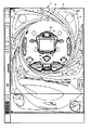
図1は、本実施例におけるパチンコ遊技機の正面図であり、主要部材の配置レイアウトを示す。パチンコ遊技機(遊技機)1は、大別して、遊技盤面を構成する遊技盤(ゲージ盤)2と、遊技盤2を支持固定する遊技機用枠(台枠)3とから構成されている。遊技盤2にはガイドレールによって囲まれた、ほぼ円形状の遊技領域が形成されている。この遊技領域のほぼ中央位置には、各々が識別可能な識別情報として特別図柄及び飾り図柄を変動可能に表示する変動表示装置となる表示装置4が設けられている。表示装置4は、例えばLCD等からなる。この表示装置4の下側には、電動チューリップ型役物(普通電動役物)5を兼用する普通可変入賞球装置(始動入賞口)6が配置されている。普通可変入賞球装置6の下側には、特別可変入賞球装置(大入賞口)7が配置されている。
【0020】
特別可変入賞球装置7は、ソレノイドによって入賞領域を開成・閉成制御する開閉板を備える。この開閉板は、通常時には閉成し、普通可変入賞球装置6への遊技球の入賞に基づいて表示装置4による可変表示ゲームが行われた結果、特定遊技状態となった場合に、ソレノイドによって入賞領域を所定期間(例えば、29秒)あるいは所定個数(例えば、10個)の入賞球が発生するまで開成(開成サイクル)する状態となるように設定され、その開成している間に遊技領域を落下する遊技球を受け止める。そして、この開成サイクルを例えば最高16回繰り返すことができるようになっている。特別可変入賞球装置7に入賞した遊技球は、所定の検出部により検出される。入賞球の検出に応答し、後述する主基板11と払出制御基板15(図2、図3)とにより、所定数の賞球の払い出しが行われる。
【0021】
また、遊技盤2の表面には、上記した構成以外にも、ランプを内蔵した風車、アウト口等が設けられている。また、パチンコ遊技機1には、点灯又は点滅する遊技効果ランプ9や効果音を発生するスピーカ8L、8Rが設けられている。
【0022】
図2は、パチンコ遊技機1の背面図であり、主要基板の配置レイアウトを示す。また、図3は、主基板を中心としたシステム構成例を示すブロック図である。図2及び図3に示すように、本実施例におけるパチンコ遊技機1は、主として、電源基板10と、主基板11と、表示制御基板12と、音声制御基板13と、ランプ制御基板14と、払出制御基板15と、情報端子基板16とを備え、それぞれ適所に配設されている。
【0023】
電源基板10は、パチンコ遊技機1内の各回路に所定の電源電圧を供給するものである。
【0024】
主基板11は、メイン側の制御基板であり、パチンコ遊技機1における遊技の進行を制御するための各種回路が搭載されている。主基板11は、主として、可変表示ゲームにおいて用いる乱数の生成機能、所定位置に配設されたスイッチ等からの信号の入力を行う機能、表示制御基板12、音声制御基板13、ランプ制御基板14及び払出制御基板15に対してそれぞれ指令情報の一例となる制御コマンドを出力して送信する機能、ホールの管理コンピュータに対して各種情報を出力する機能などを備えている。
【0025】
主基板11から表示制御基板12へ送信される制御コマンドは表示制御コマンドである。図4は、主基板11と表示制御基板12における回路構成、及び主基板11から表示制御基板12に送信される表示制御コマンドの信号線を示す図である。図4に示すように、この実施の形態では、表示制御コマンドは、表示制御信号CD0〜CD7の8本の信号線で主基板11から表示制御基板12に送信される。また、主基板11と表示制御基板12との間には、ストローブ信号を送信するための表示制御INT信号の信号線も配線されている。主基板11には、普通可変入賞球装置6や特別可変入賞球装置7、その他の入賞口への遊技球の入賞を検出するための各入賞口スイッチ70からの配線も接続されている。
【0026】
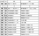
図5は、この実施の形態で用いられる主基板11から表示制御基板12に送信される表示制御コマンドの内容の一例を示す説明図である。表示制御コマンドは2バイト構成であり、1バイト目はMODE(コマンドの分類)を表し、2バイト目はEXT(コマンドの種類)を表す。MODEデータの先頭ビット(ビット7)は必ず「1」とされ、EXTデータの先頭ビットは「0」とされる。なお、図5に示されたコマンド形態は一例であって、他のコマンド形態を用いてもよい。また、この例では、制御コマンドが2つの制御信号で構成されることになるが、制御コマンドを構成する制御信号数は、1であってもよいし、3以上の複数であってもよい。
【0027】
図5に示す例において、コマンド8000(H)〜80XX(H)は、表示装置4における特別図柄及び飾り図柄の変動表示の開始を指令する変動開始コマンドである。変動開始コマンドは、図6に示すように、図柄の変動期間(総変動時間)を特定可能な表示制御コマンド、すなわち、表示に使用する変動パターンを決定するための変動パターンコマンドであり、通常ハズレ、リーチハズレ及び大当りのいずれとするかを示す情報を含んでいる。
【0028】
コマンド8F00(H)及び8F01(H)は、電源投入時に送出される特別図柄電源投入時指定コマンド及び普通図柄電源投入時指定コマンドである。なお、普通図柄電源投入時指定コマンドは、表示制御基板12が普通図柄変動制御を行う場合に用いられ、普通図柄表示器40がランプ制御基板14で制御される場合には、表示制御基板12には送出されない。
【0029】
コマンド90XX(H)は、特別図柄の予定停止図柄(最終停止図柄であるが、以下では、単に「停止図柄」ともいう)を指定する図柄指定コマンドである。後述するように、特別図柄には通常大当り図柄と確変大当り図柄とが含まれており、特別図柄の停止図柄を指定することにより、通常大当りとするか確変大当りとするかを識別することができる。すなわち、図柄指定コマンドは、確変大当りとするか否かを示す情報を含んでる。確変大当りとなると、パチンコ遊技機1が特別遊技状態となり、特別図柄の停止図柄が当り図柄となる確率が向上するとともに、普通可変入賞球装置6の開放時間と開放回数が高められる。
【0030】
コマンドA000(H)は、特別図柄の変動表示の停止を指示する確定コマンドである。また、コマンドD000(H)〜D400(H)は、普通図柄の変動パターンに関する表示制御コマンドである。ただし、普通図柄表示器40がランプ制御基板14で制御される場合には、それらのコマンドは、表示制御基板12には送出されない。
【0031】
また、主基板11には、図4に示すように、ゲーム制御用のプログラム等を記憶するROM101、ワークメモリとして使用されるRAM102、制御用のプログラムに従って制御動作を行うCPU103及びI/Oポート104を含んだ遊技制御用マイクロコンピュータ100が搭載されている。RAM102の全部又は一部は、電源基板10からのバックアップ電源でバックアップされている。
【0032】
遊技制御用マイクロコンピュータ100は、図7に示すように、特図保留メモリ120と、コマンド送信テーブルメモリ121と、ランダムカウンタ122と、変動パターンテーブルメモリ123と、特別図柄選択テーブルメモリ124と、フラグメモリ125と、変動時間タイマ126とを備えている。
【0033】
特図保留メモリ120は、遊技球が普通可変入賞球装置6に入賞して特別図柄及び飾り図柄の変動表示を開始するための条件である実行条件が成立したが、従前の変動表示を実行中である等の理由のために変動を実際に開始するための条件である開始条件が成立していない保留状態を記憶するためのメモリである。この特図保留メモリ120は、図7に示すように、4つのエントリを備え、各エントリには、普通可変入賞球装置6への入賞順に始動開始記憶番号とその入賞により抽出された乱数値(後述するランダムR1の値)が対応付けて格納される。特別図柄及び飾り図柄の変動表示が1回終了すると、最上位の情報に基づいた変動表示が実行され、第2位以下の登録情報が1位ずつ繰り上がる。また、特別図柄及び飾り図柄の変動表示中等に遊技球が普通可変入賞球装置6に新たに入賞した場合には、その入賞による乱数値が最上位の空エントリに登録される。
【0034】
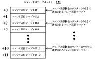
コマンド送信テーブルメモリ121には、主基板11からサブ側の各制御基板(表示制御基板12、音声制御基板13、ランプ制御基板14、及び払出制御基板15)に出力する各制御コマンドについて、複数のコマンド送信テーブルが設けられている。図8は、コマンド送信テーブルメモリ121の構成の一例として、表示制御コマンドについてのコマンド送信テーブルを示す図である。図8に示す例では、12個のコマンド送信テーブルが設けられており、使用すべきコマンド送信テーブルは、コマンド送信個数カウンタで指定される。各コマンド送信テーブルは、例えば3バイトで構成され、1バイト目にはコマンドの送り先となるサブ側の制御基板を識別するためのINTデータが設定される。また、2バイト目には、制御コマンドの1バイト目のMODEデータが設定される。そして、3バイト目には、制御コマンドの2バイト目のEXTデータが設定される。
【0035】
また、複数のコマンド送信テーブルはリングバッファとして使用される。例えば、遊技制御用マイクロコンピュータ100は、表示制御基板12に表示制御コマンドを送信する場合、コマンド送信カウンタが指しているコマンド送信テーブルに、表示制御コマンドであることを示すINTデータや、表示制御コマンドの1バイト目のMODEデータ、2バイト目のEXTデータを設定する。そして、コマンド送信個数カウンタの値を更新する。コマンド送信個数カウンタの値が12になった場合には、その値を0に戻す。
【0036】
ランダムカウンタ122は、遊技制御に用いられる判定用乱数や表示用乱数のカウントを行うものである。図9は、ランダムカウンタ122によりカウントされる各乱数を示す説明図である。ランダムカウンタ122は、図9に示すように、ランダムR1〜R5のカウントを行う。ランダムR1は、大当りを発生させてパチンコ遊技機1を特定遊技状態とするか否かを決定する大当り判定用の乱数であり、0〜299の範囲の値をとる。ランダムR2は、ハズレ時にリーチするか否かを決定するリーチ判定用の乱数であり、0〜1530の範囲の値をとる。ランダムR3は、リーチの種類を決定するための表示用の乱数であり、変動パターンの種類数XXによって定められる0〜XX−1の範囲の値をとる。ランダムR4は、ハズレ時における特別図柄の停止図柄を決定するための表示用の乱数であり、0〜5の範囲の値をとる。ランダムR5は、大当りを生じさせる確率が向上している高確率状態(特別遊技状態)とするか否かを決定する確変判定用の乱数であり、0〜9の範囲の値をとる。なお、遊技効果を高めるために、ランダムR1〜R5以外の乱数が用いられてもよい。
【0037】
変動パターンテーブルメモリ123は、表示装置4における特別図柄及び飾り図柄の変動表示で使用される複数の変動パターンの情報を示す変動パターンテーブルを記憶する。変動パターンテーブルには、例えば、ランダムカウンタ122から抽出されるランダムR1〜R3の値に基づいて、図6に示す変動パターンコマンドのいずれかを特定可能に設定されている。すなわち、変動パターンテーブルは、通常ハズレ、リーチハズレ、及び大当りのうちのいずれかの停止図柄を導出する各種の変動パターンを選択可能にする。
【0038】
特別図柄選択テーブルメモリ124は、例えば図10に示すようなハズレ時特別図柄決定用テーブル140を記憶する。ハズレ時特別図柄決定用テーブル140は、後述する特別図柄の図柄番号と、ランダムカウンタ122から抽出されるランダムR4の値とを対応付けて格納することにより、ハズレ時における特別図柄の停止図柄を特定可能とする。
【0039】
フラグメモリ125には、パチンコ遊技機1において遊技の進行を制御するために用いられる各種のフラグが設定される。例えば、フラグメモリ125には、後述する特別図柄プロセス処理(図21)において選択・実行すべき処理を示す特別図柄プロセスフラグが設けられている。また、I/Oポート104に入力される各種信号の状態や各入賞口スイッチ70から入力される検出信号の状態等に応じて各々セットあるいはクリアされる複数ビットからなる入力状態フラグや、パチンコ遊技機1において各種のエラーが発生したときに、発生したエラーの種類に対応するビットがセットされる複数ビットからなるエラーフラグが設けられている。この他、所定時間が経過してタイマ割込が発生するごとにセットされるタイマ割込フラグ等の各種のフラグが設けられている。
【0040】
変動時間タイマ126は、表示装置4における特別図柄及び飾り図柄の変動表示を開始してからの経過時間(変動時間)をメイン側で計測するためのダウンカウンタであり、主基板11が表示制御基板12に変動開始コマンドを送信するに際して、変動パターンで指定される総変動時間に対応したカウント値が初期値として設定される。
【0041】
表示制御基板12は、主基板11とは独立して可変表示ゲームにおける画像処理のための表示制御を行うものである。表示制御基板12は、主基板11から出力される表示制御コマンドに基づいて可変表示ゲームに用いられる画像を表示装置4上に表示させる。図11は、表示装置4における画像表示例を示す図である。この実施形態では、表示装置4上に、特別図柄と、装飾図柄となる左中右の飾り図柄と、始動入賞記憶数とが表示されるものとする。特別図柄は特別図柄表示エリア41において変動表示される。飾り図柄は飾り図柄表示エリア42において変動表示される。飾り図柄表示エリア42は、特別図柄表示エリア41よりも表示面積が大きく、左中右の各飾り図柄は、特別図柄よりも大きく表示されるものとする。始動入賞記憶数は、始動記憶表示エリア43において、特図保留メモリ120に保留されている入賞球数が識別可能となるように表示される。
【0042】
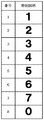
図12は、この実施の形態で用いられる特別図柄の例を示す図である。この実施の形態では、特別図柄として表示される図柄は、8図柄であり、各図柄には1〜8の図柄番号が付されている。特別図柄表示エリア41には、図12に示すような8種類の特別図柄が可変表示される。ここで、図柄番号が「8」の特別図柄「0」が表示されると、次に、図柄番号が「1」の特別図柄「1」が表示される。そして、例えば、図柄番号が「3」である特別図柄「3」を通常大当り図柄とし、図柄番号が「7」である特別図柄「7」を確変大当り図柄とする。
【0043】
すなわち、特別図柄表示エリア41における変動表示の表示結果として特別図柄「3」が導出された場合には、パチンコ遊技機1は特定遊技状態となる。また、表示結果として特別図柄「7」が導出表示された場合には、パチンコ遊技機1は特別遊技状態となる。この特別遊技状態においては、特別図柄表示エリア41における停止図柄が当り図柄になる確率が高められるとともに、普通可変入賞球装置6の開放時間と開放回数が高められる。
【0044】
図13は、この実施の形態で用いられる左中右の各飾り図柄の例を示す図である。この実施の形態では、左中右の飾り図柄として表示される各図柄は、左中右で同一の12図柄であり、各図柄には1〜12の図柄番号が付されている。飾り図柄表示エリア42には、左中右の3つの表示領域があり、各々の表示領域に図13に示すような12種類の飾り図柄が変動表示される。ここで、図柄番号が「12」の図柄が表示されると、次に、図柄番号が「1」の図柄が表示される。そして、特別図柄の停止図柄が当り図柄である場合すなわち大当り発生時には、左中右の飾り図柄が同一図柄で停止する。具体的には、特別図柄の停止図柄が「7」である確変大当りの場合には、左中右の各飾り図柄における停止図柄を「三」、「五」、「七」、「春」、「夏」、「秋」又は「冬」の同一図柄とする。また、特別図柄の停止図柄が「3」である通常大当りの場合には、左中右の各飾り図柄における停止図柄をその他の同一図柄とする。
【0045】
図4に示すように、表示制御基板12には、表示制御用のプログラム等を記憶するROM111、ワークメモリとして使用されるRAM112、制御用のプログラムに従って制御動作を行うCPU113及びI/Oポート114を含んだ表示制御用マイクロコンピュータ110が搭載されている。表示制御用マイクロコンピュータ110は、図14に示すように、受信コマンドバッファメモリ130と、ランダムカウンタ131と、プロセステーブルメモリ132と、各種タイマ133と、飾り図柄選択テーブルメモリ134と、フラグメモリ135とを備えている。
【0046】
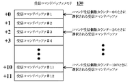
受信コマンドバッファメモリ130には、主基板11から受信した表示制御コマンドを格納するための受信コマンドバッファが複数設けられている。図15は、表示制御コマンドについての受信コマンドバッファの一構成例を示す図である。図15に示す例では、12個の受信コマンドバッファが設けられており、受信したコマンドを格納する受信コマンドバッファは、コマンド受信個数カウンタで指定される。コマンド受信個数カウンタは、0〜11の値をとる。各受信コマンドバッファは、例えば1バイトで構成され、複数の受信コマンドバッファをリングバッファとして使用することにより、2バイト構成の表示制御コマンドを6個格納することができる。
【0047】
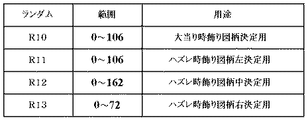
ランダムカウンタ131は、飾り図柄の停止図柄を決定するために用いられる乱数のカウントを行うものである。図16は、ランダムカウンタ131によりカウントされる各乱数を示す説明図である。ランダムカウンタ131は、図16に示すように、ランダムR10〜R13のカウントを行う。ランダムR10は、大当り時における飾り図柄の停止図柄を決定する乱数である。ランダムR11は、ハズレ時に左の飾り図柄における停止図柄を決定する乱数である。ランダムR12は、ハズレ時に中の飾り図柄における停止図柄を決定する乱数である。ランダムR13は、リーチとしない通常ハズレ時に右の飾り図柄における停止図柄を決定する乱数である。
【0048】
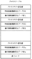
プロセステーブルメモリ132は、特別図柄及び飾り図柄の変動パターンにおける変動状態を示すデータからなるプロセステーブルを、変動パターンごとに複数記憶するためのものである。それぞれの変動パターンに対応した各プロセステーブルには、図17に示すように、時系列的に特別図柄及び飾り図柄の変動速度やその速度での変動期間、背景やキャラクタの切替タイミング等が設定されている。また、ある速度での変動期間を決めるためのプロセスタイマ値も設定されている。
【0049】
各種タイマ133は、表示装置4の表示制御に用いられる複数種類のタイマを含んで構成される。具体的には、各種タイマ133は、プロセスタイマ、変動時間タイマ、及び監視タイマを含んでいる。プロセスタイマは、プロセステーブルメモリ132から読み出されたプロセステーブルに設定されているプロセスタイマ値をカウントダウンすることにより、特別図柄及び飾り図柄をプロセステーブルに設定されている態様で変動させる変動期間を計測する。変動時間タイマは、表示装置4における特別図柄及び飾り図柄の変動表示を開始してからの経過時間(変動時間)をサブ側で計測するためのダウンカウンタであり、主基板11から受信した変動開始コマンドで指定される総変動時間に対応したカウント値が初期値として設定される。監視タイマは、変動時間タイマがタイムアウトしてからの経過時間を計測するためのものであり、主基板11から表示制御コマンドを所定時間以上受信しなかったときにタイムアウトする。
【0050】
飾り図柄選択テーブルメモリ134は、表示装置4にて変動表示される飾り図柄の停止図柄を決定するために用いられる図柄決定用テーブルを記憶する。具体的には、飾り図柄選択テーブルメモリ134は、図18(A)に示す確変大当り図柄決定用テーブル141、図18(B)に示す通常大当り図柄決定用テーブル142、図19(A)に示すハズレ時左図柄決定用テーブル143、図19(B)に示すハズレ時中図柄決定用テーブル144、及び図19(C)に示すハズレ時右図柄決定用テーブル145を格納する。
【0051】
図18(A)に示す確変大当り図柄決定用テーブル141は、確変大当りとしてパチンコ遊技機1を特別遊技状態とするとき、すなわち特別図柄の停止図柄を「7」とするときに、左中右で同一となる飾り図柄の停止図柄を決定するためのテーブルである。例えば、確変大当り図柄決定用テーブル141には、飾り図柄における停止図柄の図柄番号と、ランダムR11の値とが対応付けて格納されている。すなわち、確変大当り図柄決定用テーブル141は、ランダムカウンタ131から抽出されるランダムR11の値に基づいて、確変大当り時における飾り図柄の停止図柄を決定可能に構成されている。
【0052】
図18(B)に示す通常大当り図柄決定用テーブル142は、通常大当りとしてパチンコ遊技機1を特定遊技状態とするとき、すなわち特別図柄の停止図柄を「3」とするときに、左中右で同一となる飾り図柄の停止図柄を決定するためのテーブルである。例えば、通常大当り図柄決定用テーブル142には、確変大当り図柄決定用テーブル141と同様に、飾り図柄における停止図柄の図柄番号と、ランダムR11の値とが対応付けて格納されている。
【0053】
図19(A)に示すハズレ時左図柄決定用テーブル143は、大当りとすることなくハズレの停止図柄を導出するとき、すなわち特別図柄の停止図柄を「3」及び「7」以外の図柄とするときに、左側の飾り図柄の停止図柄を決定するためのテーブルである。例えば、ハズレ時左図柄決定用テーブル143には、左側の飾り図柄における停止図柄の図柄番号と、ランダムR12の値とが対応付けて格納されている。すなわち、ハズレ時左図柄決定用テーブル143は、ランダムカウンタ131から抽出されるランダムR12の値に基づいて、ハズレ時における左側の飾り図柄の停止図柄を決定可能に構成されている。なお、リーチとした後に大当りとすることなくハズレの停止図柄を導出するときには、右側の飾り図柄の停止図柄を、ハズレ時左図柄決定用テーブル143を用いて決定された左側の飾り図柄の停止図柄と同一のものに設定すればよい。
【0054】
図19(B)に示すハズレ時中図柄決定用テーブル144は、ハズレの停止図柄を導出するときに、中央の飾り図柄の停止図柄を決定するためのテーブルである。例えば、ハズレ時中図柄決定用テーブル144は、左側の飾り図柄の最終停止図柄番号に対する加算値と、ランダムR13の値とが対応付けて格納されている。すなわち、ハズレ時中図柄決定用テーブル144を用いてランダムR13の値に基づいて決定された加算値を、左側の飾り図柄における停止図柄の図柄番号に加算することで、ハズレ時における中央の飾り図柄の停止図柄を決定することができる。なお、リーチとした後に大当りとすることなくハズレの停止図柄を導出するときに、ハズレ時中図柄決定用テーブル144を用いて決定された加算値が「0」である場合には、導出される表示結果をハズレとするために、加算値を「1」に変更するなどしてもよい。
【0055】
図19(C)に示すハズレ時右図柄決定用テーブル145は、リーチとすることなくハズレの停止図柄を導出する通常ハズレ時に、右側の飾り図柄の停止図柄を決定するためのテーブルである。例えば、ハズレ時右図柄決定用テーブル145は、左側の飾り図柄の最終停止図柄番号に対する加算値と、ランダムR14の値とが対応付けて格納されている。図19(C)に示すように、ハズレ時右図柄決定用テーブル145に格納される加算値は1〜11の範囲の値をとり、左側の飾り図柄とは異なる図柄が停止図柄となるように設定されている。
【0056】
フラグメモリ135は、表示制御基板12が表示装置4の表示制御を行うために用いられる各種のフラグが設定される。例えば、フラグメモリ135には、後述する表示制御プロセス処理(図28)において選択・実行すべき処理を示す表示制御プロセスフラグが設けられている。また、I/Oポート114に入力される表示制御信号CD0〜CD7の状態等に応じて各々セットあるいはクリアされる複数ビットからなるコマンド受信フラグが設けられている。コマンド受信フラグの各ビットは、変動パターンコマンドとしての変動開始コマンドを受信したことを示す変動パターン受信フラグや、図柄指定コマンドを受信したことを示す有効フラグなどに割り付けられている。さらに、フラグメモリ135には、変動開始コマンドを受信したと判別した後、所定時間が経過する前に確定コマンドを受信したときにセットされるエラーフラグが設けられている。この他、所定時間が経過してタイマ割込が発生するごとにセットされるタイマ割込フラグ等の各種のフラグが設けられている。
【0057】
図2及び図3に示す音声制御基板13、ランプ制御基板14は、主基板11から送信される制御コマンドに基づいて、音声出力制御、ランプ出力制御を、それぞれ主基板11とは独立して実行するサブ側の制御基板である。なお、表示制御基板12、音声制御基板13及びランプ制御基板14は、それぞれ独立した基板として、例えば、パチンコ遊技機1の裏面において、1つのボックスに収容された状態で設置されてもよい。さらに、表示制御基板12、音声制御基板13及びランプ制御基板14を、まとめて1つの基板として構成してもよい。払出制御基板15は、遊技球の貸出や賞球等の払出制御を行うものである。情報端子基板16は、各種遊技関連情報を外部に出力するためのものである。
【0058】
次に、本実施例におけるパチンコ遊技機1の動作(作用)を説明する。図20は、主基板11に搭載された遊技制御用マイクロコンピュータ100が実行する遊技制御メイン処理を示すフローチャートである。パチンコ遊技機1に対する電源が投入されると、遊技制御メイン処理が開始され、まず、遊技制御用マイクロコンピュータ100のCPU103は、初期設定処理を実行する(ステップS101)。この初期設定処理において、割込モードやスタックポインタの設定が行われ、内蔵デバイスレジスタが初期化される。また、CTC(カウンタ/タイマ回路)及びPIO(パラレル入出力ポート)の初期化を行った後、RAM102をアクセス可能状態に設定する。
【0059】
この後、前回の電源断時にRAM102の全部又は一部について所定のデータ保護処理が行われることにより、バックアップがなされたか否かを判別する(ステップS102)。パチンコ遊技機1では、不測の電源断が生じたときに、RAM102に記憶されたデータの全部又は一部を保護するための処理が行われる。このような保護処理が行われていた場合には、バックアップありと判別される。
【0060】
ステップS102にてバックアップありと判別したときには(ステップS102;Yes)、バックアップデータのチェックとしてパリティチェックを行い、チェック結果が正常であるか否かを判別する(ステップS103)。チェック結果が正常であれば(ステップS103;Yes)、主基板11の内部状態とサブ側の各制御基板(表示制御基板12、音声制御基板13、ランプ制御基板14、及び払出制御基板15)の制御状態を電源断時の状態に戻すための遊技状態復旧処理を実行する(ステップS104)。そして、バックアップ保存されていたPC(プログラムカウンタ)の退避値が設定され、そのアドレスに復帰する。
【0061】
ステップS102にてバックアップなしと判別したときや(ステップS102;No)、ステップS103にてチェック結果が正常ではなかったときには(ステップS103;No)、ステップS105に進み、所定の初期化処理が実行される。この初期化処理では、RAM102のクリアや、所定の作業領域に対する初期値設定、サブ側の各制御基板に対する初期設定用のコマンド送出などが行われる。また、CPU103に内蔵されたCTCのレジスタ設定を行うことにより、以後、所定時間(例えば2ミリ秒)ごとにタイマ割込が発生する。
【0062】
この後、ランダムカウンタ122によりカウントされる表示用乱数であるランダムR3及びR4を更新する表示用乱数更新処理を実行するとともに(ステップS106)、フラグメモリ125に設けられたタイマ割込フラグをチェックするなどして、タイマ割込が発生したか否かを確認する(ステップS107)。フラグメモリ125に設けられたタイマ割込フラグは、CTCのレジスタ値が0となってタイマ割込が発生したときにセットされる。CPU103は、タイマ割込フラグがセットされているか否かを判別することにより、タイマ割込が発生したか否かを確認することができる。タイマ割込が発生していないときには(ステップS107;No)、ステップS106及びS107を繰り返し実行するループ処理が行われる。
【0063】
ステップS107にてタイマ割込の発生が確認されたときには(ステップS107;Yes)、所定のスイッチ処理を実行することにより、各入賞口スイッチ70から入力される検出信号の状態を判定する(ステップS108)。続いて、所定のエラー処理を実行することにより、パチンコ遊技機1の異常診断を行い、その診断結果に応じて必要ならば警告を発生可能とする(ステップS109)。この後、ランダムカウンタ122によりカウントされる判定用乱数であるランダムR1、R2及びR5を更新する判定用乱数更新処理(ステップS110)と、表示用乱数であるランダムR3及びR4を更新する表示用乱数更新処理(ステップS111)とを、順次実行する。
【0064】
次に、特別図柄プロセス処理を実行する(ステップS112)。図21は、ステップS112の特別図柄プロセス処理を示すフローチャートである。特別図柄プロセス処理を開始すると、CPU103は、まず、遊技球が普通可変入賞球装置6に入賞したか否かを、各入賞口スイッチ70に含まれる始動球検出スイッチから入力される検出信号や、フラグメモリ125に設けられた入力状態フラグなどをチェックすることにより、判別する(ステップS121)。遊技球が入賞して始動球検出スイッチからの検出信号がオン状態となった場合(ステップS121;Yes)、入賞処理を実行し(ステップS122)、遊技球が入賞していない場合(ステップS121;No)、入賞処理(ステップS122)をスキップする。
【0065】
図22は、ステップS122の入賞処理を示すフローチャートである。この入賞処理において、CPU103は、まず、特図保留メモリ120が記憶している始動入賞記憶数が最大値の4であるか否かを判別する(ステップS141)。ここで、特図保留メモリ120において、始動入賞記憶番号「4」に対応した乱数値が記憶されている場合には、始動入賞記憶数が4であると判別される。
【0066】
始動入賞記憶数が4であるときには(ステップS141;Yes)、今回の入賞による始動検出は無効として、そのまま入賞処理が終了する。一方、始動入賞記憶数が4未満であるときには(ステップS141;No)、始動入賞記憶数を1加算し(ステップS142)、ランダムカウンタ122より大当り判定用のランダムR1の値を抽出する(ステップS143)。そして、抽出した乱数値を特図保留メモリ120の空エントリの先頭にセットする(ステップS144)。
【0067】
この後、CPU103は、フラグメモリ125に格納されている特別図柄プロセスフラグの値に基づいて、図21に示すステップS130〜S136の7個の処理のいずれかを選択する。以下に、ステップS130〜S136の各処理について説明する。
【0068】
ステップS130の特別図柄通常処理は、特別図柄プロセスフラグの値が初期値「0」のときに実行される処理である。この処理において、CPU103は、特図保留メモリ120が記憶している始動入賞記憶数が0か否かを判別する。ここで、特図保留メモリ120において、始動入賞記憶番号「1」に対応した乱数値が記憶されていない場合には、始動入賞記憶数が0であると判別される。始動入賞記憶数が0であれば、表示制御基板12を介して表示装置4上にデモンストレーション画面を表示するなどして、処理を終了する。一方、始動入賞記憶数が0ではないと判別すると、特別図柄プロセスフラグの値を当り/ハズレ判定設定処理に対応した値である「1」に更新する。
【0069】
ステップS131の当り/ハズレ判定設定処理は、特別図柄プロセスフラグの値が「1」のときに実行される処理である。この処理において、CPU103は、図23に示すように、まず、特図保留メモリ120から始動入賞記憶番号「1」に対応して格納されている乱数値を読み出す(ステップS151)。この際、始動入賞記憶数を1減算し、かつ、特図保留メモリ120の第2〜第4エントリ(始動入賞記憶番号「2」〜「4」)に格納された乱数値を1エントリずつ上位にシフトする(ステップS152)。
【0070】
その後、CPU103は、ステップS151で読み出した値、すなわち抽出されているランダムR1の値に基づいて大当りとするか否かを決定する(ステップS153)。例えば、低確率時には、ランダムR1の値が「3」である場合に「大当り」と決定し、それ以外の値である場合には「ハズレ」と決定する。また、例えば、高確率時には、ランダムR1の値が「3」、「7」、「79」、「103」、「107」のいずれかである場合に「大当り」と決定し、それ以外の値である場合には「ハズレ」と決定する。
【0071】
ステップS153にて「ハズレ」と決定した場合には(ステップS153;No)、CPU103は、ランダムカウンタ122よりランダムR4の値を抽出し(ステップS154)、特別図柄選択テーブルメモリ124に記憶されたハズレ時特別図柄決定用テーブル140を用いて、特別図柄の停止図柄を決定する(ステップS155)。
【0072】
ステップS155に続いて、CPU103は、ランダムカウンタ122よりランダムR2の値を抽出し(ステップS156)、リーチとするか否かを決定する(ステップS157)。例えば、抽出したランダムR2の値が「105」〜「1530」のいずれかである場合には、リーチとしないことを決定する。一方、ランダムR2の値が「0」〜「104」のいずれかである場合には、リーチとすることを決定する。
【0073】
ステップS157にてリーチとすることを決定したときには(ステップS157;Yes)、CPU103は、ランダムカウンタ122よりランダムR3の値を抽出する(ステップS158)。そして、抽出したランダムR3の値に基づいて、変動パターンテーブルメモリ123に記憶された変動パターンテーブルを参照するなどして、リーチ種類に対応したリーチハズレ用の変動パターンを決定する(ステップS159)。
【0074】
ステップS157にてリーチとしないと決定したときには(ステップS157;No)、CPU103は、変動パターンテーブルメモリ123に記憶された変動パターンテーブルを参照するなどして通常ハズレ用の変動パターンを決定する(ステップS160)。
【0075】
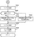
また、ステップS153にて「大当り」と決定したときには(ステップS153;Yes)、CPU103は、ランダムカウンタ122よりランダムR5の値を抽出し(図24のステップS161)、確変大当りとするか否かを決定する(ステップS162)。例えば、ランダムR5の値が奇数であるときには、確変大当りとすることを決定する。一方、ランダムR5の値が偶数であるときには、通常大当りとすることを決定する。
【0076】
ステップS162にて通常大当りとすることを決定したときには(ステップS162;No)、特別図柄の停止図柄を通常大当り用の図柄である「3」とすることを決定し(ステップS163)、確変大当りとすることを決定したときには(ステップS162;Yes)、特別図柄の停止図柄を確変大当り用の図柄である「7」とすることを決定する(ステップS164)。
【0077】
ステップS163及びS164の後、CPU103は、ランダムR3の値を抽出し(ステップS165)、該抽出されたランダムR3の値に基づいて、変動パターンテーブルメモリ123に記憶された変動パターンテーブルを参照するなどして、リーチ当り用の変動パターンを決定する(ステップS166)。こうしてステップS159、S160、及びS166のいずれかが実行された後、当り/ハズレ判定設定処理が終了するときには、特別図柄プロセスフラグの値が、特別図柄変動処理に対応した値である「2」に更新される。
【0078】
図21に示すステップS132の特別図柄変動処理は、特別図柄プロセスフラグの値が「2」のときに実行される処理である。この処理において、CPU103は、表示装置4において特別図柄及び飾り図柄の全図柄が変動開始されるように制御する。具体的には、上述した当り/ハズレ判定設定処理にて決定した特別図柄の停止図柄や変動パターンに対応する制御データを、コマンド送信テーブルメモリ121にて、コマンド送信個数カウンタにより指定されるコマンド送信テーブルに設定するなどして、変動開始コマンドと図柄指定コマンドを送信可能に設定する。そして、変動パターンに対応する総変動時間を変動時間タイマ126に設定し、変動開始コマンドが送信されるとともにカウントダウンを開始する。変動時間タイマ126がタイムアウトすると、特別図柄プロセスフラグの値を特別図柄停止時処理に対応した値である「3」に更新する。
【0079】
ステップS133の特別図柄停止時処理は、特別図柄プロセスフラグの値が「3」のときに実行される処理である。この処理において、CPU103は、主基板11から表示制御基板12に確定コマンドを送信するための設定を行う。具体的には、確定コマンドに対応する制御データを、コマンド送信テーブルメモリ121にて、コマンド送信個数カウンタにより指定されるコマンド送信テーブルに設定するなどして、確定コマンドを送信可能に設定する。そして、停止図柄が大当りに相当するときには、特別図柄プロセスフラグの値を大入賞口開放前処理に対応した値である「4」に更新し、ハズレに相当するときには、特別図柄プロセスフラグの値を「0」に更新する。
【0080】
ステップS134の大入賞口開放前処理は、特別図柄プロセスフラグの値が「4」のときに実行される処理である。この処理において、CPU103は、大入賞口としての特別可変入賞球装置7を開放する制御を開始するための設定を行う。そして、特別可変入賞球装置7を開放する制御を開始するとともに、特別図柄プロセスフラグの値を大入賞口開放中処理に対応した値である「5」に更新する。
【0081】
ステップS135の大入賞口開放中処理は、特別図柄プロセスフラグの値が「5」のときに実行される処理である。この処理において、CPU103は、開成された特別可変入賞球装置7への遊技球の入賞検出、賞球の払出指令、開成時間の計測、及び開成サイクルのラウンド数表示のための表示制御コマンド設定等を行う。CPU103は、入賞球数が所定数に達するか開成時間が所定時間に達すると、特別図柄プロセスフラグの値を更新する。具体的には、1回の大当りについて、特別可変入賞球装置7の開成回数をカウントし、開成回数が例えば16回に達していれば、特定遊技状態(大当り状態)を終了する条件が終了したとして特別図柄プロセスフラグの値を「6」に更新する。一方、開成回数が16回に達していなければ、特別可変入賞球装置7を一旦閉成した後、所定時間が経過するのを待って再度開成する。
【0082】
ステップS136の大当り終了処理は、特別図柄プロセスフラグの値が「6」のときに実行される処理であり、CPU103は、特定遊技状態を終了させる処理を行い、特別図柄プロセスフラグの値を「0」に更新する。
【0083】
以上説明したような特別図柄プロセス処理が終了すると、図20のステップS113に進み、普通図柄プロセス処理を実行する。この普通図柄プロセス処理において、CPU103は、普通図柄表示器40の表示制御内容を指示する制御データを、コマンド送信テーブルメモリ121にて、コマンド送信個数カウンタにより指定されるコマンド送信テーブルに設定するなどして、主基板11から表示制御基板12に普通図柄用の表示制御コマンドを送信可能に設定する。表示制御基板12では、主基板11から送られた表示制御コマンドに基づいた普通図柄表示器40の表示制御が行われる。具体的には、所定の実行条件が成立したときに普通図柄表示器40を制御して所定の普通図柄を所定の変動時間が経過するまで変動表示させた後、当り又はハズレの普通図柄が確定表示される。
【0084】
普通図柄プロセス処理が終了すると、所定のコマンド制御処理が実行されることにより、主基板11から表示制御基板12、音声制御基板13、ランプ制御基板14等に対して、コマンド送信テーブルに格納されている制御コマンドを送出する(ステップS114)。また、CPU103は、所定の情報出力処理を実行することにより、各種出力データの格納領域の内容をI/Oポート104に含まれる各出力ポートに出力する(ステップS115)。この情報出力処理では、主基板11から情報端子基板16に、大当り情報、始動情報、確率変動情報などをホール管理用コンピュータに対して出力する指令の送出も行われる。
【0085】
続いて、CPU103は、所定のソレノイド出力処理を実行することにより、所定の条件が成立したときに普通電動役物5や特別可変入賞球装置7の開閉駆動を行う(ステップS116)。そして、CPU103は、所定の賞球処理を実行することにより、各入賞口スイッチ70から入力された検出信号に基づく賞球数の設定などを行い、払出制御基板15に対して払出制御コマンドを出力可能とする(ステップS117)。
【0086】
次に、表示制御基板12に搭載された表示制御用マイクロコンピュータ110の動作を説明する。図25は、表示制御用マイクロコンピュータ110が実行する表示制御メイン処理を示すフローチャートである。表示制御メイン処理を開始すると、まず、CPU113が初期化処理を実行することにより、RAM112のクリアや各種初期値の設定、また表示制御の起動間隔を決めるための33ミリ秒タイマの初期設定等が行われる(ステップS201)。その後、CPU113は、フラグメモリ135に設けられたタイマ割込フラグを監視し、タイマ割込フラグがセットされるまでループ処理を実行する(ステップS202;No)。このループ処理では、ランダムカウンタ131がカウントするランダムR10〜R13を更新する乱数更新処理が実行される。この実施の形態では、CPU113にて33ミリ秒ごとにタイマ割込が発生し、このタイマ割込が発生すると、所定のタイマ割込処理を実行することにより、フラグメモリ135に設けられたタイマ割込フラグがセットされる。
【0087】
CPU113では、33ミリ秒ごとに発生するタイマ割込とは別に、主基板11からの表示制御コマンドを受信するための割込が発生する。この割込は、主基板11からの表示制御INT信号がオン状態となることにより発生する割込である。表示制御INT信号がオン状態となることによる割込が発生すると、CPU113は、自動的に割込禁止状態に設定するが、自動的に割込禁止状態にならないCPUを用いている場合には、割込禁止命令(DI命令)を発行することが好ましい。
【0088】
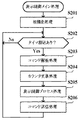
主基板11からの表示制御INT信号がオン状態となることによりCPU113において割込がかかることで、図26のフローチャートに示すコマンド受信割込処理の実行が開始される。このコマンド受信割込処理において、CPU113は、まず、各レジスタの値をスタックに退避する(ステップS211)。続いて、I/Oポート114のうちで表示制御コマンドデータの入力に割り当てられている入力ポートから、データを読み込む(ステップS212)。そして、2バイト構成の表示制御コマンドのうちの1バイト目であるか否かを判別する(ステップS213)。ここで、表示制御コマンドの1バイト目(MODE)と2バイト目(EXT)とは、受信側で直ちに区別可能に構成されている。すなわち、先頭ビットによって、MODEとしてのデータを受信したのかEXTとしてのデータを受信したのかを、受信側において直ちに検出できる。受信したコマンドの先頭ビットが「1」である場合には、2バイト構成である表示制御コマンドのうちの有効な1バイト目(MODEデータ)を受信したと判別される。
【0089】
ステップS213にて1バイト目のMODEデータであると判別したときには(ステップS213;Yes)、受信コマンドバッファメモリ130にて、コマンド受信個数カウンタにより指定される受信コマンドバッファに、受信したコマンドを格納する(ステップS214)。ステップS214を実行した後には、ステップS220に進む。一方、表示制御コマンドの1バイト目でなければ(ステップS213;No)、1バイト目のMODEデータを既に受信したか否かを判別する(ステップS215)。1バイト目のMODEデータを既に受信したか否かは、受信コマンドバッファに格納されているコマンドデータを確認することにより、判別することができる。
【0090】
1バイト目を既に受信している場合には(ステップS215;Yes)、今回受信した1バイトのうちの先頭ビットが「0」であるか否かを判別し、先頭ビットが「0」であれば、有効な2バイト目を受信したとして、コマンド受信個数カウンタにより指定される次の受信コマンドバッファに、受信したコマンドを格納する(ステップS216)。なお、ステップS216にて表示制御コマンドの1バイト目を受信していないと判別した場合や(ステップS216;No)、2バイト目として受信したデータのうちの先頭ビットが「0」でない場合には、ステップS220に進む。
【0091】
ステップS216にて2バイト目のコマンドデータを格納すると、コマンド受信個数カウンタの値を2加算し(ステップS217)、その値が12以上であるか否かを判別する(ステップS218)。12以上であれば(ステップS218;Yes)、コマンド受信個数カウンタをクリアして、その値を0に戻す(ステップS219)。一方、12未満のときには(ステップS218;No)、ステップS219をスキップする。その後、ステップS211にて退避されていたレジスタを復帰し(ステップS220)、割込許可に設定する(ステップS221)。
【0092】
こうしてコマンド受信割込処理により、主基板11から送られた表示制御コマンドが受信コマンドバッファメモリ130に設けられた受信コマンドバッファに格納される一方で、図25に示すステップS202にてタイマ割込の発生が確認される。このタイマ割込の発生が確認されると(ステップS202;Yes)、CPU113は、所定のコマンド解析処理を実行することにより、受信した表示制御コマンドを解析する(ステップS203)。
【0093】
図27は、ステップS203のコマンド解析処理を示すフローチャートである。このコマンド解析処理を開始すると、CPU113は、まず、受信コマンドバッファメモリ130に設けられた受信コマンドバッファに、主基板11から受信した表示制御コマンドが格納されているか否かを確認する(ステップS231)。コマンドが格納されているか否かは、コマンド受信個数カウンタの値と読出ポインタとを比較することによって判定される。両者が一致しているときには、受信コマンドが格納されていない。受信コマンドバッファに受信コマンドが格納されているときには(ステップS231;Yes)、CPU113が受信コマンドバッファから受信コマンドを読み出す(ステップS232)。なお、読み出したら読出ポインタの値を+1しておく。
【0094】
CPU113は、読み出した受信コマンドが図柄指定コマンドであるか否かを判別する(ステップS233)。図柄指定コマンドであれば(ステップS233;Yes)、そのコマンドのEXTデータをRAM112に確保された特別図柄用の停止図柄格納エリアに格納するとともに(ステップS234)、対応する有効フラグをセットする(ステップS235)。図柄指定コマンドのEXTデータは、特別図柄の図柄番号を示すデータとなっている。これに対して、ステップS232にて読み出した受信コマンドが図柄指定コマンドではないときには(ステップS233;No)、ステップS234及びS235をスキップする。
【0095】
続いて、CPU113は、ステップS232にて読み出した受信コマンドが変動パターンコマンドとなる変動開始コマンドであるか否かを判別する(ステップS236)。変動パターンコマンドであれば(ステップS236;Yes)、そのコマンドのEXTデータをRAM112に確保された変動パターン格納エリアに格納してセーブするとともに(ステップS237)、フラグメモリ135に設けられた変動パターン受信フラグをセットする(ステップS238)。これに対して、ステップS232にて読み出した受信コマンドが変動パターンコマンドではないときには(ステップS236;No)、ステップS237及びS238をスキップする。
【0096】
また、読み出した受信コマンドがその他の表示制御コマンドであるときには、フラグメモリ135に設けられたコマンド受信フラグにて、受信した表示制御コマンドに対応するビットをセットし(ステップS239)、ステップS231にリターンする。こうして受信コマンドバッファに格納された全ての受信コマンドに対応した各種の処理が実行され、全ての受信コマンドが読み出されると、コマンド解析処理が終了する。
【0097】
このようなコマンド解析処理が終了すると、図25に示すステップS205に進み、表示制御プロセス処理を実行する。図28は、ステップS205の表示制御プロセス処理を示すフローチャートである。この表示制御プロセス処理において、CPU113は、フラグメモリ135に設けられている表示制御プロセスフラグの値に基づいて、図28に示すステップS240〜S245の6個の処理のいずれかを選択する。以下に、ステップS240〜S245の各処理について説明する。
【0098】
ステップS240の変動パターンコマンド受信待ち処理は、表示制御プロセスフラグの値が初期値「0」のときに実行される処理である。この処理において、CPU113は、図29に示すように、まず、フラグメモリ135に設けられた変動パターン受信フラグがセットされているか否かを判別する(ステップS251)。上述したコマンド受信割込処理において、変動時間を特定可能な変動パターンコマンドとしての変動開始コマンドを受信したときには、変動パターン受信フラグがセットされる。
【0099】
ステップS251にて変動パターン受信フラグがセットされているときには(ステップS251;Yes)、変動パターンフラグをクリアし(ステップS252)、表示制御プロセスフラグの値を飾り図柄演出設定処理に対応した値である「1」に更新する(ステップS253)。一方、変動パターン受信フラグがセットされていないときには(ステップS251;No)、そのまま変動パターンコマンド受信待ち処理が終了する。
【0100】
図28に示すステップS241の飾り図柄演出設定処理は、表示制御プロセスフラグの値が「1」のときに実行される処理である。図30〜図32は、ステップS241の飾り図柄演出設定処理を示すフローチャートである。この飾り図柄演出設定処理を開始すると、CPU113は、まず、RAM112の変動パターン格納エリアに格納されているデータを読み出すなどして、主基板11から受信した変動パターンコマンドに基づいて飾り図柄の変動パターンを決定する(ステップS261)。続いて、フラグメモリ135に設けられたコマンド受信フラグにて確定コマンドに対応するビットをチェックするなどして、確定コマンドを受信しているか否かを判別する(ステップS262)。
【0101】
ここで、上述したステップS240の変動パターンコマンド受信待ち処理にて変動開始コマンドを受信したことが確認されると、表示制御プロセスフラグの値が「1」に更新され、次のタイマ割込が発生したときに実行される表示制御プロセス処理にて、ステップS241の飾り図柄演出設定処理が実行されることとなる。この実施例では、CPU113にてタイマ割込が33ミリ秒ごとに発生することから、CPU113は、変動開始コマンドを受信したことを確認した後、33ミリ秒が経過するより前に確定コマンドを受信したときには、ステップS262にて確定コマンドを受信していると判別する。これに対して、変動開始コマンドの受信が確認された後、33ミリ秒が経過しても確定コマンドを受信していないときには、ステップS262にて確定コマンドを受信していないと判別する。
【0102】
ステップS262にて確定コマンドを受信していると判別したときには(ステップS262;Yes)、フラグメモリ135に設けられたエラーフラグをセットするとともに(ステップS263)、変動パターンコマンドに基づいて表示結果を判定する(ステップS264)。変動パターンコマンドとしての変動開始コマンドは、通常ハズレ、リーチハズレ及び大当りのいずれとするかを示す情報を含んでおり、CPU113は、この変動パターンコマンドに基づいて表示結果を判定することができる。この判定の結果として、大当りとするか否かを決定する(ステップS265)。
【0103】
大当りとしないことを決定したときには(ステップS265;No)、初期指定のハズレ図柄を飾り図柄の停止図柄とすることを決定する(ステップS266)。なお、初期指定のハズレ図柄は、リーチとなることのない通常ハズレ図柄であり、予めROM111あるいはRAM112の初期指定ハズレ図柄格納エリアに格納されており、電源投入時に初期表示結果として表示装置4の飾り図柄表示エリア42に表示される。
【0104】
一方、ステップS265にて大当りとすることを決定したときには(ステップS265;Yes)、所定の通常大当り図柄を飾り図柄の停止図柄とすることを決定する(ステップS267)。具体的には、図柄番号が最小(例えば、「1」)の図柄を、左中右の飾り図柄における停止図柄として設定する。ステップS266あるいはS267を実行した後には、表示プロセスフラグの値を図柄停止待ち処理に対応した値である「4」に更新し(ステップS284)、飾り図柄演出設定処理を終了する。
【0105】
また、ステップS262にて確定コマンドを受信していないと判別したときには(ステップS262;No)、フラグメモリ135に設けられたコマンド受信フラグにて有効フラグをチェックし、その有効フラグがセットされているか否かを判別する(ステップS268)。有効フラグがセットされているときには(ステップS268;Yes)、RAM112に確保された特別図柄用の停止図柄格納エリアに格納されているデータを読み出す(ステップS269)。有効フラグがセットされているとき、RAM112の特別図柄用の停止図柄格納エリアには、図柄指定コマンドのEXTデータが格納されているので、この停止図柄格納エリアの格納データを読み出すことにより、図柄指定コマンドの内容を特定することができる。
【0106】
ステップS269にて格納データを読み出したCPU113は、変動パターンコマンドと図柄指定コマンドの内容が合致しているか否かを判別する(ステップS270)。例えば、変動パターンコマンドが通常ハズレとすることを示す情報を含んでいる一方で、図柄指定コマンドにより指定された特別図柄の停止図柄が「3」あるいは「7」であるときには、変動パターンコマンドと図柄指定コマンドの内容に不一致が生じている。
【0107】
ステップS270にて変動パターンコマンドと図柄指定コマンドの内容が合致しているときには(ステップS270;Yes)、図柄指定コマンドに基づいて表示結果を判定する(図31に示すステップS271)。この判定の結果として、まず、大当りとするか否かを決定し(ステップS272)、大当りとすることを決定したときには(ステップS272;Yes)、さらに、確変大当りとするか否かを決定する(ステップS273)。図柄指定コマンドは、確変大当りとするか否かを示す情報を含んでおり、CPU113は、この図柄指定コマンドに基づいて確変大当りとするか否かを決定することができる。
【0108】
ステップS273にて確変大当りとすることを決定したときには(ステップS273;Yes)、飾り図柄の停止図柄を決定するためのテーブルとして、飾り図柄選択テーブルメモリ134に格納されている図柄決定用テーブルのうちから確変大当り図柄決定用テーブル141を選択する(ステップS274)。一方、ステップS273にて確変大当りとしない、すなわち通常大当りとすることを決定したときには(ステップS273;No)、飾り図柄の停止図柄を決定するためのテーブルとして、通常大当り図柄決定用テーブル142を選択する(ステップS275)。この後、CPU113は、ランダムカウンタ131からランダムR10の値を抽出し、ステップS274あるいはS275にて選択した図柄決定用テーブルを参照することにより、抽出されたランダムR10の値に基づいて左中右の飾り図柄における停止図柄を決定する(ステップS276)。ステップS276を実行した後には、表示プロセスフラグの値を図柄変動開始処理に対応した値である「2」に更新し(ステップS285)、飾り図柄演出設定処理を終了する。
【0109】
図30に示すステップS268にて有効フラグがセットされていないときや(ステップS268;No)、ステップS270にて変動パターンコマンドと図柄指定コマンドの内容が合致しないときには(ステップS270;No)、変動パターンコマンドに基づいて表示結果を判定する(図32に示すステップS277)。この判定結果として、CPU113は、大当りとするか否かを決定する(ステップS278)。ステップS278にて大当りとすることを決定したときには(ステップS278;Yes)、所定の通常大当り図柄を飾り図柄の停止図柄とすることを決定し(ステップS286)、ステップS285に進んで表示プロセスフラグの値を「2」に更新する。
【0110】
ステップS278にて大当りとしないことを決定したとき(ステップS278;No)、あるいは図31に示すステップS272にて大当りとしないことを決定したときには(ステップS272;No)、左側の飾り図柄における停止図柄を決定するためのテーブルとして、飾り図柄選択テーブルメモリ134に格納されている図柄決定用テーブルのうちからハズレ時左図柄決定用テーブル143を選択する(ステップS279)。この後、CPU113は、ランダムカウンタ131からランダムR11の値を抽出し、ステップS279にて選択したハズレ時左図柄決定用テーブル143を参照することにより、抽出されたランダムR11の値に基づいて左側の飾り図柄における停止図柄を決定する(ステップS280)。
【0111】
続いて、CPU113は、リーチとするか否かを決定する(ステップS281)。変動パターンコマンドには、通常ハズレ、リーチハズレ及び大当りのいずれとするかを示す情報を含んでいることから、CPU113は、この変動パターンコマンドに基づいてリーチとするか否かを決定することができる。リーチとしないことを決定したときには(ステップS281;No)、ランダムカウンタ131からランダムR12及びR13の値を抽出し、ハズレ時中図柄決定用テーブル144及びハズレ時右図柄決定用テーブル145を参照するなどして、右側の飾り図柄における停止図柄を左側の飾り図柄とは異なるものとすることを決定し、中央の飾り図柄として任意の図柄を決定する(ステップS282)。一方、リーチとすることを決定したときには(ステップS281;Yes)、右側の飾り図柄における停止図柄を左側の飾り図柄と同一のものとすることを決定するとともに、ランダムカウンタ131からランダムR12の値を抽出し、ハズレ時中図柄決定用テーブル144を参照するなどして、抽出されたランダムR12の値に基づいて左右の飾り図柄とは異なる図柄を中央の飾り図柄における停止図柄とすることを決定する(ステップS283)。ステップS282あるいはS283を実行した後には、ステップS285に進み、表示プロセスフラグの値を「2」に更新する。
【0112】
このような飾り図柄演出設定処理が実行されることにより、飾り図柄の停止図柄配列は、変動パターンの内容、変動開始コマンドを受信したことが確認されてから確定コマンドを受信するまでの経過時間、及び図柄指定コマンドの内容の組み合わせに基づいて、決定される。図33は、飾り図柄演出設定処理を実行することにより選択される飾り図柄の停止図柄配列を示す説明図である。
【0113】
図33に示すように、変動パターンコマンドとしての変動開始コマンドが通常ハズレあるいはリーチハズレとすることを示す情報を含んでおり(「変動パターン」が「ハズレ」)、変動開始コマンドの受信を確認してから33ミリ秒が経過する前に確定コマンドを受信したときには(「変動開始からの経過時間」が「33ms未満」)、図柄指定コマンドの内容に関係なく、初期指定のハズレ図柄を飾り図柄の停止図柄とすることが決定される。また、変動開始コマンドが大当りとすることを示す情報を含んでおり(「変動パターン」が「当り」)、変動開始コマンドの受信を確認してから33ミリ秒が経過する前に確定コマンドを受信したときには(「変動開始からの経過時間」が「33ms未満」)、図柄指定コマンドの内容に関係なく、所定の通常大当り図柄を飾り図柄の停止図柄とすることが決定される。このように、変動開始コマンドを受信したと判別してから所定時間が経過する前に確定コマンドを受信したときには、変動開始コマンドに対応した表示結果を、導出する表示結果として選択する。これにより、確定コマンドを正しく受信できないときでも、変動開始コマンドにより指示された表示態様に対応する遊技状態に近い表示結果を確実に導出することが可能となる。
【0114】
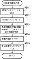
図28に示すステップS242の図柄変動開始処理は、表示制御プロセスフラグの値が「2」のときに実行される処理である。この処理において、CPU113は、図34に示すように、まず、主基板11から送出された変動開始コマンドに基づいて決定した変動パターンに対応するプロセステーブルを使用するための設定を行う(ステップS291)。具体的には、プロセステーブルメモリ132の読出ポインタに、使用するプロセステーブルの先頭アドレスを設定するなどして、プロセステーブルに設定された情報を順次読み出すことができるように設定する。また、CPU113は、各種タイマ133に含まれる変動時間タイマに、変動開始コマンドにて指示された特別図柄及び飾り図柄の総変動時間に対応するカウント初期値をセットする。
【0115】
このとき、CPU113は、特別図柄の停止図柄が確変大当り図柄であるか、通常大当り図柄であるかに応じて、使用するプロセステーブルの種類を異ならせるようにしてもよい。すなわち、特別図柄及び飾り図柄の変動表示に使用するプロセステーブルを、主基板11から送信された変動開始コマンドなどから特定される変動パターンだけでなく、特別図柄の停止図柄とも対応づけ、特別図柄の停止図柄が異なれば使用するプロセステーブルも異なるものとなるように設定してもよい。ただし、主基板11における制御との整合性を保つため、それぞれの変動パターンに対応したプロセステーブルによる特別図柄及び飾り図柄の総変動時間は、対応づけられた特別図柄の停止図柄が異なるものであっても、同一となるように設定される。このような構成によれば、変動パターンが同一であっても、特別図柄の停止図柄が確変大当り図柄であるか、通常大当り図柄であるかに応じて、特別図柄及び飾り図柄の変動表示における変動態様を異ならせることができる。
【0116】
続いて、CPU113は、使用することが決定されたプロセステーブルの先頭に設定されているプロセスタイマ値を各種タイマ133に含まれるプロセスタイマにセットして、カウントダウンをスタートさせる(ステップS292)。また、プロセスタイマ値と対応付けられた特別図柄表示制御データ及び飾り図柄表示制御データに従って表示装置4を制御することにより、特別図柄と飾り図柄の変動表示を開始する(ステップS293)。そして、特別図柄及び飾り図柄の総変動時間がセットされた変動時間タイマのカウントダウンをスタートさせる(ステップS294)。この後、表示制御プロセスフラグの値を図柄変動中処理に対応した値である「3」に更新する(ステップS295)。
【0117】
図28に示すステップS243の図柄変動中処理は、表示制御プロセスフラグの値が「3」のときに実行される処理である。この処理において、CPU113は、図35に示すように、まず、この時点で確定コマンドを受信しているか否かを判別する(ステップS301)。確定コマンドを受信していると判別したときには(ステップS301;Yes)、確定コマンドを正規のタイミングで受信できなかったことを示すエラーフラグをセットする(ステップS302)。このエラーフラグは、フラグメモリ135に設けられている。ステップS302にてエラーフラグをセットしたときには、ステップS309に進み、表示プロセスフラグの値を図柄停止待ち処理に対応する値である「4」に更新する。
【0118】
一方、ステップS301にて確定コマンドを受信していないときには(ステップS301;No)、CPU113は、各種タイマ133に含まれるプロセスタイマがタイムアウトしたか否かを判別する(ステップS303)。プロセスタイマがタイムアウトしたときには(ステップS303;Yes)、プロセステーブルメモリ132における読出ポインタの値を更新することにより、プロセステーブルの読出位置を切り替える(ステップS304)。CPU113は、このようにして切り替えられた読出位置からプロセスタイマ値、特別図柄表示制御データ、及び飾り図柄表示制御データを読み出し、該読み出されたプロセスタイマ値を、プロセスタイマにセットする。新たなプロセスタイマ値をセットされたプロセスタイマが再びカウントダウンを開始するとともに(ステップS305)、CPU113は、そのプロセスタイマ値と対応付けられた特別図柄表示制御データ及び飾り図柄表示制御データに従って、表示装置4の制御を変更する(ステップS306)。プロセスタイマがタイムアウトしていないときには(ステップS303;No)、ステップS304〜S306をスキップする。
【0119】
続いて、各種タイマ133に含まれる変動時間タイマがタイムアウトしたか否かを判別する(ステップS307)。変動時間タイマがタイムアウトしたときには(ステップS307;Yes)、各種タイマ133に含まれる監視タイマに対して予め定められたタイマ初期値を設定し、その監視タイマのカウントダウンをスタートさせるとともに(ステップS308)、表示制御プロセスフラグの値を図柄停止待ち処理に対応する値である「4」に更新する(ステップS309)。変動時間タイマがタイムアウトしていないときには(ステップS307;No)、ステップS308及びS309をスキップする。
【0120】
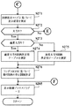
図28に示すステップS244の図柄停止待ち処理は、表示制御プロセスフラグの値が「4」のときに実行される処理である。この処理において、CPU113は、図36に示すように、まず、確定コマンドを表示制御コマンドとして受信したか否かを判別する(ステップS311)。確定コマンドを受信しているときには(ステップS311;Yes)、さらに、フラグメモリ135に設けられたエラーフラグがセットされてオンとなっている否かを判別する(ステップS312)。このエラーフラグは、確定コマンドを正規のタイミングで受信できなかったときにセットされる。
【0121】
ステップS312にてエラーフラグがオフであると判別したときには(ステップS312;No)、正規のタイミングで確定コマンドを受信したとして、表示装置4において実行中である特別図柄及び飾り図柄の変動表示を停止させ、各図柄における停止図柄を確定表示する制御を行い(ステップS313)、停止図柄が大当り図柄であるか否かを判別する(ステップS314)。大当り図柄であるときには(ステップS314;Yes)、表示制御プロセスフラグの値を大当り表示処理に対応した値である「5」に更新し(ステップS315)、大当り図柄ではないときには(ステップS314;No)、表示制御プロセスフラグの値を「0」に更新する(ステップS316)。
【0122】
ステップS312にてエラーフラグがオンであると判別したときには(ステップS312;Yes)、正規のタイミングで確定コマンドを受信できなかったとして、表示装置4で特別図柄表示エリアにて変動表示されている特別図柄をエラーが生じた旨の表示結果に切り替えて表示するとともに、左中右の各飾り図柄における停止図柄を確定表示する制御を行う(ステップS317)。この後、ステップS316に進み、表示制御プロセスフラグの値を「0」に更新する。
【0123】
また、ステップS311にて確定コマンドを受信していないと判別したときには(ステップS311;No)、監視タイマがタイムアウトしたか否かを判別し(ステップS318)、タイムアウトしているときには(ステップS318;Yes)何らかの異常が発生したと判断して、表示装置4上に所定のエラー画面を表示する制御を行う(ステップS319)。ステップS319を実行した後は、ステップS316に進み、表示制御プロセスフラグの値を「0」に更新する。
【0124】
一方、監視タイマがタイムアウトしていないと判別したときには(ステップS318;No)、監視タイマのタイマ値を1減算するなどした後に、表示制御プロセスフラグの値を変更することなく、図柄停止待ち処理が終了する。
【0125】
図28に示すステップS245の大当り表示処理は、表示制御プロセスフラグの値が「5」のときに実行される処理である。この処理において、CPU113は、表示装置4を制御することにより、確変大当りにより発生する特別遊技状態や、通常大当りにより発生する特定遊技状態に応じた画像を表示する制御を行う。そして、特別遊技状態や特定遊技状態が終了すると、表示制御プロセスフラグの値を「0」に更新する。
【0126】
図37は、この実施の形態における図柄の表示例を示す図である。図37(A)は、初期指定のハズレ図柄となる図柄の表示例を示す。図37(A)に示す例では、特別図柄表示エリア41に表示されるハズレ時の特別図柄が「4」である。また、飾り図柄表示エリア42に表示される左側の飾り図柄が「一」、中央の飾り図柄が「二」、右側の飾り図柄が「三」である。
【0127】
図37(B)は、通常大当り図柄の表示例を示す。図37(B)に示す例では、特別図柄表示エリア41に表示される特別図柄が「3」であり、飾り図柄の停止図柄として「一」が表示される。この実施例では、図30に示す飾り図柄演出設定処理のステップS267にて、左中右の各飾り図柄における停止図柄を、図37(B)に示す図柄とすることが決定されるものとする。
【0128】
図37(C)は、図30に示す飾り図柄演出設定処理のステップS266にて飾り図柄の停止図柄を初期指定のハズレ図柄とすることを決定したときの停止図柄の表示例を示す。図37(C)に示す例では、エラーを報知するための表示結果として、特別図柄表示エリア41にエラー報知用の図柄「E」が表示される。
【0129】
図37(D)は、図30に示す飾り図柄演出設定処理にてステップS267が実行された場合の表示例を示す。図37(D)に示す例でも、図37(C)の場合と同様に、特別図柄表示エリア41にエラー報知用の図柄「E」が表示される。フラグメモリ135に設けられたエラーフラグがセットされているときには、図36に示す図柄停止待ち処理のステップS317にて、図37(C)及び(D)に示すようなエラー報知用の図柄「E」を特別図柄表示エリア41に表示する制御が行われる。このように、表示制御基板12にて主基板11からの表示制御コマンド(具体的には、確定コマンド)を正しく受信できない場合には、通常使用される特別図柄とは異なる図柄が特別図柄表示エリア41に表示される。これにより、遊技者は、エラーが発生したことを容易に認識することができる。
【0130】
以上説明したように、この実施の形態によれば、表示制御用マイクロコンピュータ110のCPU113が変動開始コマンドを受信したと判別してから所定時間が経過するより前に確定コマンドを受信したときには、変動開始コマンドに対応した表示結果が選択される。これにより、表示制御基板12にて表示装置4における表示を制御するためのコマンドを正しく受信できない場合でも、特別図柄及び飾り図柄の変動表示を行うことができ、遊技状態に近い表示を行うことができる。
【0131】
ここで、変動開始コマンドは、通常ハズレ、リーチハズレ及び大当りのいずれとするかを示す情報を含んでいる。また、図柄指定コマンドは、確変大当りとするか否かを示す情報を含んでいる。これにより、1つのコマンドが受信できない場合でも極力遊技状態に近い表示結果を導出することができる。
【0132】
また、表示制御用マイクロコンピュータ110のCPU113は、変動開始コマンドが大当りとすることを示す情報を含んでおり、変動開始コマンドを受信したと判別してから33ミリ秒が経過する前に確定コマンドを受信したときには、図30のステップS267にて、所定の通常大当り図柄を飾り図柄の停止図柄として選択する。これにより、確定コマンドを正しく受信できない場合でも、変動開始コマンドにより指定された「大当り」に対応する表示結果を導出することができる。
【0133】
また、表示制御用マイクロコンピュータ110のCPU113は、変動開始コマンドが通常ハズレあるいはリーチハズレを示す情報を含んでおり、変動開始コマンドを受信したと判別してから33ミリ秒が経過する前に確定コマンドを受信したときには、図30のステップS266にて、初期指定のハズレ図柄を飾り図柄の停止図柄として選択する。これにより、確定コマンドを正しく受信できない場合でも、変動開始コマンドにより指定された「ハズレ」に対応する表示結果を導出することができる。さらに、初期指定のハズレ図柄は電源投入時に表示される初期表示結果であることから、データの共用が可能となり、データ量を低減することができる。
【0134】
CPU113は、確定コマンドを正規のタイミングで受信できないときに、図30のステップS263あるいは図35のステップS302にて、フラグメモリ135に設けられたエラーフラグをセットする。そして、図36のステップS312にてエラーフラグがセットされていると判別したときに、ステップS317にてエラー報知用の図柄を特別図柄表示エリア41に表示する制御を行う。これにより、コマンドエラー発生時に、その旨を遊技者等に知らせることができる。
【0135】
ここで、飾り図柄表示エリア42は、特別図柄表示エリア41よりも表示面積が大きい。また、CPU113は、図35のステップS317にて、飾り図柄表示エリア42に左中右の各飾り図柄における停止図柄を表示するとともに、特別図柄表示エリア41にエラー報知用の図柄を表示する制御を行う。これにより、エラー発生時に特別図柄が当り図柄となることを防止して、遊技者の不快感を減少させることができるとともに、エラーが発生したことを遊技者等に知らせることができる。
【0136】
なお、上記実施の形態では、変動開始コマンドを受信したと判別してから33ミリ秒が経過する前に確定コマンドを受信したときに、変動開始コマンドに対応した表示結果を選択するものとして説明した。しかしながら、この発明はこれに限定されるものではなく、任意の所定時間を予め設定し、該所定時間が経過する前に確定コマンドを受信したときに、変動開始コマンドに対応した表示結果を選択するようにしてもよい。
【0137】
また、図30のステップS266にて停止図柄とすることが決定される初期指定のハズレ図柄は、ハズレ図柄となる任意の図柄であればよい。同様に、図30のステップS267にて停止図柄とすることが決定される通常大当り図柄は、通常大当り図柄となる任意の図柄であればよい。
【0138】
また、上記実施の形態では、エラー報知用の図柄を特別図柄表示エリア41に表示することで、コマンドが正しく受信できなかった旨を遊技者等に知らせるものとして説明したが、これに限定されるものではない。例えば、表示制御基板12は、音声制御基板13やランプ制御基板14により音声出力やランプ出力を制御するようにし、警告音の出力や所定のランプの点灯あるいは点滅を行わせることで、コマンドが正しく受信できなかった旨を遊技者等に知らせるようにしてもよい。ここで、エラー報知用の図柄の表示による報知、警告音の出力による報知、ランプの点灯あるいは点滅による報知は、別々に行うようにしてもよいし、複数種類の報知を互いに組み合わせて行うようにしてもよい。
【0139】
上記実施の形態では、図29に示す変動パターンコマンド受信待ち処理にて変動パターン受信フラグがセットされていると判別したときに、図30〜図32に示す飾り図柄演出設定処理を実行した後、図34に示す図柄変動開始処理を実行することで特別図柄と飾り図柄の変動表示を開始するものとして説明した。しかしながら、この発明は、これに限定されるものではなく、変動開始コマンドを受信した時点で直ちに特別図柄及び飾り図柄の変動表示を開始するようにしてもよい。この場合、プロセステーブルメモリ132には、所定の記憶領域を設け、その記憶領域に、予め所定時間(例えば、33ミリ秒)に対応する変動表示の変動態様を示すデータからなるプロセステーブルを記憶しておく。
【0140】
また、この場合、CPU113は、図29に示す変動パターンコマンド受信待ち処理に代えて、図38に示す処理を実行する。図38に示す処理では、図29に示すステップS252に続いて、ステップS400〜S403が実行される。すなわち、CPU113は、ステップS252に続いて、プロセステーブルメモリ132に記憶されている変動開始コマンド受信時用のプロセステーブルを使用するための設定を行う(ステップS400)。このプロセステーブルには、表示制御基板12が主基板11から送信された変動開始コマンドを受信したときから所定時間(例えば、33ミリ秒)が経過するまでの変動表示の表示態様が設定されている。そして、ステップS400にて設定したプロセステーブルに基づき、図34に示すステップS292〜S294と同様にして、特別図柄と飾り図柄の変動表示を開始する(ステップS401〜S403)。なお、図38に示す処理を実行するときには、図34に示すステップS292〜S294はスキップするようにすればよい。
【0141】
このように、変動開始コマンドを受信してから所定時間が経過するまでの変動表示の変動態様を示すプロセステーブルを使用することで、変動開始コマンドを受信したときに直ちに変動表示を開始し、コマンドを正しく受信できるか否かに関わらず、所定時間が経過するまでは一定の表示態様で変動表示を行うことができる。これにより、コマンドが正しく受信できずに変動パターンを決定できないときでも、変動表示を途切れさせることなく制御することができ、遊技者に不信感を与えない表示を行うことができる。
【0142】
図1及び図2に示した装置構成、図3、図4、図7及び図14に示すブロック構成や、図20〜図32及び図34〜図36に示すフローチャートの構成は、発明の趣旨を逸脱しない範囲で任意に変更及び修正が可能である。
【0143】
さらに、パチンコ遊技機1の動作をシミュレーションするゲーム機などにも本発明を適用することができる。本発明を実現するためのプログラム及びデータは、コンピュータ装置等に対して、着脱自在の記録媒体により配布・提供される形態に限定されるものではなく、予めコンピュータ装置等の有する記憶装置にプリインストールしておくことで配布される形態を採っても構わない。さらに、本発明を実現するためのプログラム及びデータは、通信処理部を設けておくことにより、通信回線等を介して接続されたネットワーク上の、他の機器からダウンロードすることによって配布する形態を採っても構わない。
【0144】
そして、ゲームの実行形態も、着脱自在の記録媒体を装着することにより実行するものだけではなく、通信回線等を介してダウンロードしたプログラム及びデータを、内部メモリ等にいったん格納することにより実行可能とする形態、通信回線等を介して接続されたネットワーク上における、他の機器側のハードウェア資源を用いて直接実行する形態としてもよい。さらには、他のコンピュータ装置等とネットワークを介してデータの交換を行うことによりゲームを実行するような形態とすることもできる。
【0145】
【発明の効果】
以上説明したように本発明は、以下に示す効果を有する。
【0146】
請求項1に記載の遊技機によれば、変動開始判別手段が変動開始コマンドを受信したと判別してから所定時間が経過する前に確定コマンドを受信したときには、識別情報指定コマンドの種類によらずに、変動開始コマンドの種類のみに基づいて表示結果を選択決定する。これにより、変動表示装置における表示を制御するコマンドを正しく受信できないときでも、識別情報の変動表示を行うことができ、遊技状態に近い表示を行うことができる。
【0147】
請求項2に記載の遊技機においては、識別情報指定コマンドが特別遊技状態を発生させるか否かを示す情報を含んでいるので、1つのコマンドが受信できない場合でも極力遊技状態に近い表示結果を導出することができ、遊技者に不快感を与えない表示を行うことができる。
【0148】
請求項3に記載の遊技機においては、変動開始コマンドにより特定表示結果とすることが指定されており、かつ、所定時間が経過する前に確定コマンドを受信したときには、装飾識別情報の表示結果として特別表示結果以外で特定表示結果と整合する表示結果を選択決定するので、確定コマンドを正しく受信できないときでも、変動開始コマンドにより指定された特定表示状態に極力近づけた表示結果を導出することができる。
【0149】
請求項4に記載の遊技機においては、変動開始コマンドにより特別識別情報の表示結果を特定表示結果としないことが指定されており、所定時間が経過する前に確定コマンドを受信したときには、装飾識別情報の表示結果として特定表示結果及びリーチ表示態様以外の初期表示結果を選択するので、確定コマンドを正しく受信できないときでも、変動開始コマンドにより指定された表示態様に極力近づけて、ハズレとなる表示結果を確実に導出することができる。また、表示結果を電源投入時に表示される初期表示結果とすることで、データの共用を可能とし、データ量を低減することができる。
【0150】
請求項5に記載の遊技機においては、表示制御手段は、所定時間が経過する前に確定コマンドを受信したときには所定の報知を行うので、コマンドを正しく受信できなかった旨を遊技者等に知らせることができる。
【0151】
請求項6に記載の遊技機においては、変動表示装置が特別表示部と、特別表示部よりも表示面積が大きい装飾表示部とを含み、所定時間が経過する前に確定コマンドを受信したときに、特別表示部を用いて所定の報知としての報知表示を行う。これにより、コマンドを正しく受信できないときに特別識別情報が特定表示結果となることを防止して、遊技者の不快感を減少させることができるとともに、コマンドを正しく受信できなかった旨を遊技者等に知らせることができる。
【図面の簡単な説明】
【図1】本発明の実施の形態におけるパチンコ遊技機の正面図である。
【図2】本発明の実施の形態におけるパチンコ遊技機の背面図である。
【図3】主基板を中心としたシステム構成例を示すブロック図である。
【図4】主基板と表示制御基板の間を接続する信号線等を示すブロック図である。
【図5】表示制御コマンドの内容の一例を示す図である。
【図6】変動開始コマンドの内容の一例を示す図である。
【図7】遊技制御用マイクロコンピュータの構成例を示す図である。
【図8】コマンド送信テーブルメモリの構成例を示す図である。
【図9】遊技制御用マイクロコンピュータのランダムカウンタによりカウントされる各乱数の例を示す図である。
【図10】ハズレ時特別図柄決定用テーブルの例を示す図である。
【図11】表示装置における画像表示例を示す図である。
【図12】この実施の形態で用いられる特別図柄の例を示す図である。
【図13】この実施の形態で用いられる左中右の飾り図柄の例を示す図である。
【図14】表示制御用マイクロコンピュータの構成例を示す図である。
【図15】受信コマンドバッファメモリの構成例を示す図である。
【図16】表示制御用マイクロコンピュータのランダムカウンタによりカウントされる各乱数の例を示す図である。
【図17】プロセステーブルの構成例を示す図である。
【図18】確変大当り図柄決定用テーブル及び通常大当り図柄決定用テーブルの例を示す図である。
【図19】ハズレ時左図柄決定用テーブル、ハズレ時中図柄決定用テーブル及びハズレ時右図柄決定用テーブルの例を示す図である。
【図20】遊技制御メイン処理を示すフローチャートである。
【図21】特別図柄プロセス処理を示すフローチャートである。
【図22】図21における入賞処理の詳細を示すフローチャートである。
【図23】図21における当り/ハズレ判定設定処理の詳細を示すフローチャートである。
【図24】図21における当り/ハズレ判定設定処理の詳細を示すフローチャートである。
【図25】表示制御メイン処理を示すフローチャートである。
【図26】コマンド受信割込処理を示すフローチャートである。
【図27】コマンド解析処理を示すフローチャートである。
【図28】表示制御プロセス処理を示すフローチャートである。
【図29】図28における変動パターンコマンド受信待ち処理の詳細を示すフローチャートである。
【図30】図28における飾り図柄演出設定処理の詳細を示すフローチャートである。
【図31】図28における飾り図柄演出設定処理の詳細を示すフローチャートである。
【図32】図28における飾り図柄演出設定処理の詳細を示すフローチャートである。
【図33】飾り図柄演出設定処理を実行することにより選択される飾り図柄の停止図柄配列を示す説明図である。
【図34】図28における図柄変動開始処理の詳細を示すフローチャートである。
【図35】図28における図柄変動中処理の詳細を示すフローチャートである。
【図36】図28における図柄停止待ち処理の詳細を示すフローチャートである。
【図37】この実施の形態における図柄の表示例を示す図である。
【図38】本発明の変形例における変動パターンコマンド受信待ち処理を示すフローチャートである。
【符号の説明】
1 … パチンコ遊技機(遊技機)
2 … 遊技盤(ゲージ盤)
3 … 遊技機用枠(台枠)
4 … 表示装置
5 … 電動チューリップ型役物(普通電動役物)
6 … 普通可変入賞球装置(始動入賞口)
7 … 特別可変入賞球装置(大入賞口)
8L、8R … スピーカ
9 … 遊技効果ランプ
10 … 電源基板
11 … 主基板
12 … 表示制御基板
13 … 音声制御基板
14 … ランプ制御基板
15 … 払出制御基板
16 … 情報端子基板
40 … 普通図柄表示器
41 … 特別図柄表示エリア
42 … 飾り図柄表示エリア
43 … 始動記憶表示エリア
70 … 各入賞口スイッチ
100 … 遊技制御用マイクロコンピュータ
101、111 … ROM
102、112 … RAM
103、113 … CPU
104、114 … I/Oポート
110 … 表示制御用マイクロコンピュータ
120 … 特図保留メモリ
121 … コマンド送信テーブルメモリ
122、131 … ランダムカウンタ
123 … 変動パターンテーブルメモリ
124 … 特別図柄選択テーブルメモリ
125、135 … フラグメモリ
126 … 変動時間タイマ
130 … 受信コマンドバッファメモリ
132 … プロセステーブルメモリ
133 … 各種タイマ
134 … 飾り図柄選択テーブルメモリ
140 … ハズレ時特別図柄決定用テーブル
141 … 確変大当り図柄決定用テーブル
142 … 通常大当り図柄決定用テーブル
143 … ハズレ時左図柄決定用テーブル
144 … ハズレ時中図柄決定用テーブル
145 … ハズレ時右図柄決定用テーブル[0001]
TECHNICAL FIELD OF THE INVENTION
The present invention relates to a pachinko gaming machine, and more particularly, to a gaming machine that performs a game using a variable display of identification information.
[0002]
[Prior art]
In a gaming machine such as a pachinko gaming machine, a display device such as a liquid crystal display device (hereinafter, LCD: Liquid Crystal Display) displays predetermined identification information (hereinafter referred to as a display symbol) in an updated manner, thereby performing a variable display. There have been provided a number of games in which a so-called variable display game is used to determine whether or not a predetermined game value is to be given based on the result, thereby enhancing the interest in the game.
[0003]
The variable display game mainly uses the above-described display device as an image display device, and shifts to a jackpot game state which is advantageous to the player when the display result becomes a predetermined specific display result. There is. When shifting to the jackpot gaming state, a special winning combination or a special electric accessory called an attacker is opened to continuously provide the player with a state in which winning of the game ball is extremely easy for a certain period of time.
[0004]
In recent gaming machines, in order to reduce the burden of control on game control means (circuits) for controlling the progress and control of games, control of effects relating to display symbols is separated from the game control means and formed on a sub-board. Image information displayed on the display device is controlled by display control means operating according to display control command data from the game control means. Since the game control means and the display control means are separated as described above, an error may occur in the display control command due to noise or the like. Therefore, when the display control means cannot correctly receive a command from the game control means, as a gaming machine that performs display as close as possible to the normal fluctuation display, a plurality of commands to be received during one fluctuation are correctly set. When it is determined that there is a command that cannot be received, there has been a concept of performing display control according to the command that has been correctly received (for example, Patent Document 1).
[0005]
[Patent Document 1]
JP 2000-317093
[0006]
Here, as a plurality of commands to be received in order to control one variation display, a variation start command instructing a variation start of a display symbol, a symbol designation command designating a stop symbol derived as a display result, and Some use a symbol confirmation command for instructing derivation of a display result.
[0007]
[Problems to be solved by the invention]
However, if the content of the display control is determined only according to the command that has been correctly received, the progress of the game may not match the display on the display device. For example, when determining the display mode of the variable display of the display symbol based on the variable start command and the symbol designating command, conventionally, when any command could not be correctly received, the display is performed based only on the correctly received command. Since only the control is performed, the progress of the game does not match the display on the display device so much that a problem occurs between the player and the game store.
[0008]
The present invention has been made in view of the above situation, and provides a gaming machine capable of performing a display closer to a gaming state even when the display control means cannot properly receive a command from the game control means. The purpose is to provide.
[0009]
[Means for Solving the Problems]
In order to achieve the above object, a gaming machine according to
[0010]
According to the configuration of the first aspect, when a change command is received before a predetermined time elapses after the change start determining unit determines that the change start command transmitted from the game control unit has been received, the display is performed. The result determining means selects and determines the display result based only on the type of the change start command, regardless of the type of the identification information specifying command. Thus, even when the display control unit cannot correctly receive a command for controlling the display on the variable display device, the variable display of the identification information can be performed, and a display close to a game state can be performed.
[0011]
In the gaming machine according to
[0012]
4. The gaming machine according to
[0013]
In the gaming machine according to
[0014]
In the gaming machine according to the fifth aspect, the display control means performs a predetermined notification when a determination command is received before the predetermined time has elapsed. Thereby, it is possible to notify a player or the like that the command has not been correctly received. Note that the display control means performs error notification by, for example, performing display of a symbol for error notification, output of a warning sound, and lamp output by the variable display device separately or in combination with each other. You may.
[0015]
7. The gaming machine according to
[0016]
BEST MODE FOR CARRYING OUT THE INVENTION
Hereinafter, an embodiment of the present invention will be described in detail with reference to the drawings. In the following description, the term “reach” means that a stopped symbol (called a “reach symbol”) constitutes a part of a big hit symbol and a symbol that has not been stopped yet (a “reach variable symbol”) is displayed in a variable manner. Or a state in which all or some of the symbols constitute all or part of the big hit symbol and are synchronously displayed in a variable manner. Specifically, in a plurality of predetermined display areas, an effective line that becomes a big hit when the predetermined symbol stops is determined, and a predetermined symbol is displayed in a part of the display area on the effective line. Is in a state where the variable display is performed in the display area on the activated line that has not been stopped when the display is stopped (for example, the left, middle display area of the left, middle, and right display areas has a big hit symbol). (For example, “7”), the display area on the right is in a state where the variable display is still being performed in a state where the display is stopped, or all or a part of the display area on the activated line Are displayed in a synchronized manner while forming all or a part of the big hit symbol (for example, the same is applied to all of the left, middle, and right display areas, regardless of which state is displayed. Variation display is performed when the symbols are aligned And is that state). At the time of the reach, an unusual effect may be performed by a lamp or sound. This production is called reach production. In addition, at the time of the reach, a character (an effect display imitating a person or the like, which is different from the design) may be displayed, or the display mode of the background may be changed. This change in the display of the character and the display of the background is called reach effect display.
[0017]
The gaming machine in the present embodiment is a gaming machine for performing a special map game using an image display device such as an LCD, and a card reader (CR: Card Reader) type first-type pachinko gaming machine for lending a ball with a prepaid card. And a gaming machine such as a slot machine equipped with an LCD.
[0018]
In addition, even if it is a ball and ball game machine such as a pachinko game machine, as long as it has an image display device, for example, a pachinko game machine classified into the second or third type, a general electric machine, or A ball game machine with a probability setting function called a pachicon may be used. Further, the present invention is applicable not only to a CR-type pachinko gaming machine that lends a ball using a prepaid card, but also to a pachinko gaming machine that lends a ball using cash. That is, any game machine having an image display device such as an LCD and capable of variably displaying symbols as identification information may be used.
[0019]
FIG. 1 is a front view of a pachinko gaming machine according to the present embodiment, and shows an arrangement layout of main members. The pachinko gaming machine (gaming machine) 1 is roughly divided into a gaming board (gauge board) 2 constituting a gaming board surface, and a gaming machine frame (base frame) 3 for supporting and fixing the
[0020]
The special variable winning
[0021]
In addition to the above-described configuration, a windmill with a built-in lamp, an outlet, and the like are provided on the surface of the
[0022]
FIG. 2 is a rear view of the
[0023]
The
[0024]
The
[0025]
The control command transmitted from the
[0026]
FIG. 5 is an explanatory diagram showing an example of the content of a display control command transmitted from the
[0027]
In the example shown in FIG. 5, commands 8000 (H) to 80XX (H) are variation start commands for instructing the
[0028]
Commands 8F00 (H) and 8F01 (H) are a special symbol power-on designation command and a normal symbol power-on designation command which are sent out when the power is turned on. The normal symbol power-on designation command is used when the
[0029]
The command 90XX (H) is a symbol designation command for designating a scheduled stop symbol of a special symbol (which is a final stop symbol, but is also simply referred to as a “stop symbol” below). As described later, the special symbol includes a normal big hit symbol and a probable big hit symbol. By designating the stop symbol of the special symbol, it is possible to identify whether the normal big hit or the probable big hit is specified. . That is, the symbol designating command includes information indicating whether or not to make a probability change big hit. When the probability change big hit occurs, the
[0030]
The command A000 (H) is a confirmation command for instructing the stop of the special symbol change display. The commands D000 (H) to D400 (H) are display control commands relating to a variation pattern of a normal symbol. However, when the
[0031]
As shown in FIG. 4, the
[0032]
As shown in FIG. 7, the
[0033]
In the special
[0034]
In the command
[0035]
Also, a plurality of command transmission tables are used as a ring buffer. For example, when the
[0036]
The
[0037]
The variation
[0038]
The special symbol
[0039]
In the
[0040]
The
[0041]
The
[0042]
FIG. 12 is a diagram showing an example of a special symbol used in this embodiment. In this embodiment, the symbols displayed as special symbols are eight symbols, and each symbol is assigned a symbol number of 1 to 8. In the special
[0043]
That is, when the special symbol “3” is derived as a display result of the variable display in the special
[0044]
FIG. 13 is a diagram showing an example of each of the left, middle, and right decorative patterns used in this embodiment. In this embodiment, the symbols displayed as the left-middle-right decorative symbols are the same twelve symbols in the left-middle-right, and each symbol is assigned a symbol number of 1 to 12. The decorative
[0045]
As shown in FIG. 4, the
[0046]
The reception
[0047]
The
[0048]
The
[0049]
The
[0050]
The decorative symbol
[0051]
When the
[0052]
The normal jackpot symbol determination table 142 shown in FIG. 18 (B) indicates that when the
[0053]
The loss-time left symbol determination table 143 shown in FIG. 19 (A) is used to derive a stop symbol of a loss without making a big hit, that is, a stop symbol of a special symbol is a symbol other than “3” and “7”. Sometimes, it is a table for determining a stop symbol of the left decorative symbol. For example, in the loss-time left symbol determination table 143, the symbol number of the stop symbol in the left decorative symbol and the value of the random R12 are stored in association with each other. In other words, the loss-time left symbol determination table 143 is configured to be able to determine the stop symbol of the left-side decorative symbol at the time of the loss based on the value of the random R12 extracted from the
[0054]
The loss-time middle symbol determination table 144 shown in FIG. 19B is a table for determining the stop symbol of the central decorative symbol when deriving the loss symbol. For example, the loss-time middle symbol determination table 144 stores an added value to the last stop symbol number of the left decorative symbol and the value of the random R13 in association with each other. That is, by adding the added value determined based on the value of the random R13 using the loss-time middle symbol determination table 144 to the symbol number of the stop symbol in the left-side decorative symbol, the central decorative symbol at the time of the loss. Stop symbols can be determined. In addition, when deriving the stop symbol of the loss without reaching the big hit after the reach, when the added value determined by using the symbol determination table 144 during the loss is "0", it is derived. The added value may be changed to “1” in order to change the display result.
[0055]
The loss-time right symbol determination table 145 shown in FIG. 19C is a table for determining the stop symbol of the right decorative symbol at the time of a normal loss in which a stop symbol of the loss is derived without reaching. For example, the loss-time right symbol determination table 145 stores an added value to the last stop symbol number of the left decorative symbol and the value of the random R14 in association with each other. As shown in FIG. 19 (C), the added value stored in the loss-time right symbol determination table 145 takes a value in the range of 1 to 11, and a symbol different from the decorative symbol on the left becomes a stop symbol. Is set.
[0056]
In the
[0057]
The
[0058]
Next, an operation (action) of the
[0059]
Thereafter, when a predetermined data protection process is performed on all or a part of the
[0060]
When it is determined in step S102 that there is a backup (step S102; Yes), a parity check is performed as a check of the backup data, and it is determined whether the check result is normal (step S103). If the check result is normal (step S103; Yes), the internal state of the
[0061]
When it is determined in step S102 that there is no backup (step S102; No), or when the check result is not normal in step S103 (step S103; No), the process proceeds to step S105, and a predetermined initialization process is executed. You. In this initialization processing, clearing of the
[0062]
Thereafter, display random number updating processing for updating the random numbers R3 and R4, which are display random numbers counted by the
[0063]
When the occurrence of the timer interruption is confirmed in step S107 (step S107; Yes), the state of the detection signal input from each winning
[0064]
Next, a special symbol process is executed (step S112). FIG. 21 is a flowchart showing the special symbol process of step S112. When the special symbol process process is started, the
[0065]
FIG. 22 is a flowchart showing the winning process of step S122. In this prize processing, the
[0066]
When the number of start winning prizes stored is four (step S141; Yes), the start detection based on the current prize is invalidated, and the prize processing ends as it is. On the other hand, when the number of stored start winnings is less than 4 (Step S141; No), the number of stored started winnings is incremented by 1 (Step S142), and the value of the random R1 for big hit determination is extracted from the random counter 122 (Step S143). ). Then, the extracted random number value is set at the head of an empty entry in the special figure holding memory 120 (step S144).
[0067]
Thereafter, based on the value of the special symbol process flag stored in the
[0068]
The special symbol normal process of step S130 is a process executed when the value of the special symbol process flag is the initial value “0”. In this process, the
[0069]
The hit / loss determination setting process in step S131 is a process executed when the value of the special symbol process flag is “1”. In this process, as shown in FIG. 23, the
[0070]
Thereafter, the
[0071]
If "losing" is determined in step S153 (step S153; No), the
[0072]
Subsequent to step S155, the
[0073]
When the reach is determined in step S157 (step S157; Yes), the
[0074]
When it is determined in step S157 that the reach is not to be reached (step S157; No), the
[0075]
Further, when it is determined as “big hit” in step S153 (step S153; Yes), the
[0076]
If it is determined in step S162 that a normal big hit is to be made (step S162; No), it is determined that the stop symbol of the special symbol is "3" which is a symbol for a normal big hit (step S163). When it is determined that the special symbol is to be performed (step S162; Yes), it is determined that the stop symbol of the special symbol is "7" which is a symbol for the probability change big hit (step S164).
[0077]
After steps S163 and S164, the
[0078]
The special symbol change process of step S132 shown in FIG. 21 is a process executed when the value of the special symbol process flag is “2”. In this processing, the
[0079]
The special symbol stop-time process of step S133 is a process executed when the value of the special symbol process flag is “3”. In this process, the
[0080]
The special winning opening pre-processing of step S134 is processing executed when the value of the special symbol process flag is “4”. In this process, the
[0081]
The special winning opening opening process in step S135 is a process executed when the value of the special symbol process flag is “5”. In this process, the
[0082]
The big hit end process in step S136 is a process executed when the value of the special symbol process flag is “6”. The
[0083]
When the special symbol process as described above is completed, the process proceeds to step S113 in FIG. 20, and the normal symbol process is executed. In the ordinary symbol processing, the
[0084]
When the normal symbol process processing is completed, a predetermined command control processing is executed, whereby the
[0085]
Subsequently, the
[0086]
Next, the operation of the
[0087]
In the
[0088]
The
[0089]
If it is determined in step S213 that the received data is the first byte MODE data (step S213; Yes), the received command is stored in the reception
[0090]
If the first byte has already been received (step S215; Yes), it is determined whether or not the first bit of the one byte received this time is “0”, and if the first bit is “0”. For example, assuming that the valid second byte has been received, the received command is stored in the next received command buffer designated by the command reception number counter (step S216). If it is determined in step S216 that the first byte of the display control command has not been received (step S216; No), or if the first bit of the data received as the second byte is not “0”, , And the process proceeds to step S220.
[0091]
When the command data of the second byte is stored in step S216, the value of the command reception number counter is incremented by 2 (step S217), and it is determined whether or not the value is 12 or more (step S218). If it is 12 or more (step S218; Yes), the command reception number counter is cleared and its value is returned to 0 (step S219). On the other hand, if it is less than 12 (Step S218; No), Step S219 is skipped. Thereafter, the register saved in step S211 is restored (step S220), and interrupt permission is set (step S221).
[0092]
As a result of the command reception interruption processing, the display control command sent from the
[0093]
FIG. 27 is a flowchart showing the command analysis processing in step S203. When this command analysis processing is started, the
[0094]
The
[0095]
Subsequently, the
[0096]
If the read reception command is another display control command, a bit corresponding to the received display control command is set by a command reception flag provided in the flag memory 135 (step S239), and the process returns to step S231. I do. In this way, various processes corresponding to all the received commands stored in the received command buffer are executed, and when all the received commands are read, the command analysis process ends.
[0097]
Upon completion of such a command analysis process, the process proceeds to step S205 shown in FIG. 25 to execute a display control process process. FIG. 28 is a flowchart showing the display control process in step S205. In this display control process, the
[0098]
The fluctuation pattern command reception waiting process in step S240 is a process executed when the value of the display control process flag is the initial value “0”. In this process, as shown in FIG. 29, the
[0099]
When the variation pattern reception flag is set in step S251 (step S251; Yes), the variation pattern flag is cleared (step S252), and the value of the display control process flag is a value corresponding to the decorative symbol effect setting processing. It is updated to "1" (step S253). On the other hand, when the variation pattern reception flag has not been set (step S251; No), the variation pattern command reception waiting process ends as it is.
[0100]
The decorative symbol effect setting process of step S241 shown in FIG. 28 is a process executed when the value of the display control process flag is “1”. FIG. 30 to FIG. 32 are flowcharts showing the decorative symbol effect setting processing in step S241. When the decoration design effect setting process is started, the
[0101]
Here, when it is confirmed that the fluctuation start command has been received in the fluctuation pattern command reception waiting processing in step S240 described above, the value of the display control process flag is updated to “1”, and the next timer interrupt occurs. In the display control process process executed when this is done, the decorative symbol effect setting process of step S241 is executed. In this embodiment, since the timer interrupt occurs in the
[0102]
When it is determined in step S262 that the confirmation command has been received (step S262; Yes), an error flag provided in the
[0103]
When it is determined not to make a big hit (Step S265; No), it is determined that the initially specified losing symbol is a stop symbol of the decorative symbol (Step S266). Note that the initially specified losing symbol is a normal losing symbol that does not become a reach, and is stored in advance in the initially specified losing symbol storage area of the
[0104]
On the other hand, when it is determined that a big hit is to be made in step S265 (step S265; Yes), it is determined that a predetermined normal big hit symbol is a stop symbol of the decorative symbol (step S267). Specifically, the symbol with the smallest symbol number (for example, “1”) is set as the stop symbol in the left middle right decorative symbol. After executing step S266 or S267, the value of the display process flag is updated to “4” corresponding to the symbol stop waiting process (step S284), and the decorative symbol effect setting process ends.
[0105]
When it is determined in step S262 that the confirmation command has not been received (step S262; No), the validity flag is checked with the command reception flag provided in the
[0106]
The
[0107]
When the contents of the fluctuation pattern command and the symbol designation command match in step S270 (step S270; Yes), the display result is determined based on the symbol designation command (step S271 shown in FIG. 31). As a result of this determination, first, it is determined whether or not to make a big hit (step S272), and when it is determined to make a big hit (step S272; Yes), it is further determined whether or not to make a big change big hit (step S272). Step S273). The symbol designating command includes information indicating whether or not to make the probability change big hit, and the
[0108]
If it is determined in step S273 that it is a probability change big hit (step S273; Yes), the symbol determining table stored in the decorative symbol
[0109]
When the valid flag is not set in step S268 shown in FIG. 30 (step S268; No), or when the contents of the fluctuation pattern command and the symbol designation command do not match in step S270 (step S270; No), the fluctuation pattern The display result is determined based on the command (step S277 shown in FIG. 32). As a result of this determination, the
[0110]
When it is determined not to make a big hit in step S278 (step S278; No), or when it is determined not to make a big hit in step S272 shown in FIG. 31 (step S272; No), the stop symbol in the decorative symbol on the left side. Is selected from the symbol determination tables stored in the decorative symbol selection table memory 134 (step S279). Thereafter, the
[0111]
Subsequently, the
[0112]
By executing such a decorative symbol effect setting process, the stop symbol array of the decorative symbol, the content of the variation pattern, the elapsed time from when it is confirmed that the variation start command is received to when the finalization command is received, And it is determined based on a combination of the contents of the symbol designating command. FIG. 33 is an explanatory diagram showing a stop symbol arrangement of a decorative symbol selected by executing the decorative symbol effect setting process.
[0113]
As shown in FIG. 33, the variation start command as the variation pattern command includes information indicating that the loss is a normal loss or a reach loss (“variation pattern” is “loss”), and the reception of the variation start command is confirmed. If the confirmation command is received before the elapse of 33 milliseconds from the start ("Elapsed time since the start of fluctuation" is "less than 33 ms"), the initial design of the lost design is stopped regardless of the content of the design specification command. It is determined to be a symbol. In addition, information indicating that the fluctuation start command is a big hit is included (“variation pattern” is “hit”), and a confirmation command is received before 33 milliseconds elapse after confirming the reception of the fluctuation start command. When this is done (“the elapsed time from the start of the change” is “less than 33 ms”), it is determined that the predetermined normal big hit symbol is the stop symbol of the decorative symbol regardless of the content of the symbol designating command. As described above, when the determination command is received before the predetermined time elapses after determining that the fluctuation start command has been received, the display result corresponding to the fluctuation start command is selected as the derived display result. This makes it possible to reliably derive a display result close to the gaming state corresponding to the display mode specified by the change start command even when the confirmation command cannot be correctly received.
[0114]
The symbol change start process in step S242 shown in FIG. 28 is a process executed when the value of the display control process flag is “2”. In this process, as shown in FIG. 34, first, the
[0115]
At this time, the
[0116]
Subsequently, the
[0117]
The symbol change process in step S243 shown in FIG. 28 is a process executed when the value of the display control process flag is “3”. In this process, as shown in FIG. 35, the
[0118]
On the other hand, when the determination command has not been received in step S301 (step S301; No), the
[0119]
Next, it is determined whether or not the variable time timer included in the
[0120]
The symbol stop waiting process in step S244 shown in FIG. 28 is a process executed when the value of the display control process flag is “4”. In this process, as shown in FIG. 36, the
[0121]
When it is determined in step S312 that the error flag is off (step S312; No), the display of the special symbol and the decoration symbol being executed on the
[0122]
When it is determined in step S312 that the error flag is ON (step S312; Yes), it is determined that the confirmation command could not be received at regular timing, and the special display variablely displayed in the special symbol display area on the
[0123]
If it is determined in step S311 that the confirmation command has not been received (step S311; No), it is determined whether or not the monitoring timer has timed out (step S318). If it has timed out (step S318; Yes) ) It determines that some abnormality has occurred, and performs control to display a predetermined error screen on the display device 4 (step S319). After executing step S319, the process advances to step S316 to update the value of the display control process flag to “0”.
[0124]
On the other hand, when it is determined that the monitoring timer has not timed out (step S318; No), the symbol stop waiting process is performed without changing the value of the display control process flag after subtracting 1 from the timer value of the monitoring timer. finish.
[0125]
The big hit display process in step S245 shown in FIG. 28 is a process executed when the value of the display control process flag is “5”. In this process, by controlling the
[0126]
FIG. 37 is a diagram showing a display example of a symbol in this embodiment. FIG. 37 (A) shows a display example of a symbol that will be an initially specified losing symbol. In the example shown in FIG. 37 (A), the special symbol at the time of the loss displayed in the special
[0127]
FIG. 37 (B) shows a display example of a normal big hit symbol. In the example shown in FIG. 37B, the special symbol displayed in the special
[0128]
FIG. 37 (C) shows a display example of a stop symbol when it is determined in step S266 of the decorative symbol effect setting process shown in FIG. 30 that the stop symbol of the decorative symbol is to be the initially specified loss symbol. In the example shown in FIG. 37 (C), a symbol “E” for error notification is displayed in the special
[0129]
FIG. 37D shows a display example in the case where step S267 is executed in the decorative symbol effect setting processing shown in FIG. In the example shown in FIG. 37 (D), a symbol “E” for error notification is displayed in the special
[0130]
As described above, according to this embodiment, when the
[0131]
Here, the change start command includes information indicating which of a normal loss, a reach loss, and a big hit. Further, the symbol designating command includes information indicating whether or not to make a probability change big hit. This makes it possible to derive a display result as close to the gaming state as possible even when one command cannot be received.
[0132]
Further, the
[0133]
In addition, the
[0134]
The
[0135]
Here, the decorative
[0136]
Note that, in the above embodiment, the display result corresponding to the change start command is selected when the determination command is received before the elapse of 33 milliseconds after the determination that the change start command has been received. . However, the present invention is not limited to this, and an arbitrary predetermined time is set in advance, and when a confirmation command is received before the predetermined time has elapsed, a display result corresponding to the fluctuation start command is selected. You may do so.
[0137]
Further, the initially-designated losing symbol determined to be the stop symbol in step S266 in FIG. 30 may be any symbol that is a losing symbol. Similarly, the normal jackpot symbol determined to be the stop symbol in step S267 of FIG. 30 may be any symbol that is a normal jackpot symbol.
[0138]
Further, in the above embodiment, the symbol for error notification is displayed in the special
[0139]
In the above embodiment, when it is determined that the variation pattern reception flag is set in the variation pattern command reception waiting process shown in FIG. 29, the decoration symbol effect setting process shown in FIGS. The description has been given on the assumption that the variable display of the special symbol and the decorative symbol is started by executing the symbol variation start process shown in FIG. However, the present invention is not limited to this, and the variation display of the special symbol and the decoration symbol may be started immediately upon receiving the variation start command. In this case, a predetermined storage area is provided in the
[0140]
In this case, the
[0141]
As described above, by using the process table indicating the variation mode of the variation display from when the variation start command is received until the predetermined time elapses, the variation display is started immediately when the variation start command is received, and the command is displayed. Irrespective of whether or not it can be correctly received, the variable display can be performed in a fixed display mode until a predetermined time elapses. Thereby, even when the variation pattern cannot be determined because the command cannot be received correctly, the variation display can be controlled without interruption, and a display that does not give the player distrust can be performed.
[0142]
The apparatus configuration shown in FIGS. 1 and 2, the block configuration shown in FIGS. 3, 4, 7, and 14, and the configuration of the flowcharts shown in FIGS. 20 to 32 and 34 to 36 denote the purpose of the invention. Any changes and modifications can be made without departing from the scope of the present invention.
[0143]
Further, the present invention can be applied to a game machine or the like that simulates the operation of the
[0144]
The game can be executed not only by attaching a detachable recording medium, but also by storing programs and data downloaded via a communication line or the like in an internal memory or the like. Alternatively, the program may be directly executed using hardware resources of another device on a network connected via a communication line or the like. Furthermore, the game may be executed by exchanging data with another computer device or the like via a network.
[0145]
【The invention's effect】
As described above, the present invention has the following effects.
[0146]
According to the gaming machine of the first aspect, when a change command is received before a predetermined time elapses after the change start determining means determines that the change start command has been received, the change in the type of the identification information designation command is performed. Instead, the display result is selected and determined based only on the type of the fluctuation start command. Thus, even when a command for controlling the display on the variable display device cannot be correctly received, the variable display of the identification information can be performed, and a display close to a gaming state can be performed.
[0147]
In the gaming machine according to the second aspect, since the identification information designation command includes information indicating whether or not to generate a special gaming state, even if one command cannot be received, a display result as close to the gaming state as possible is obtained. It can be derived, and a display that does not cause discomfort to the player can be performed.
[0148]
In the gaming machine according to the third aspect, it is specified that the specific display result is to be obtained by the change start command, and when the confirmation command is received before the predetermined time has elapsed, the display result of the decoration identification information is displayed. Since the display result that matches the specific display result other than the special display result is selected and determined, the display result that is as close as possible to the specific display state specified by the fluctuation start command can be derived even when the finalization command cannot be correctly received. .
[0149]
In the gaming machine according to the fourth aspect, it is specified by the change start command that the display result of the special identification information is not to be the specific display result, and when the confirmation command is received before the predetermined time has elapsed, the decoration identification is performed. Since the initial display result other than the specific display result and the reach display mode is selected as the information display result, even when the finalization command cannot be received correctly, the display result that is as close as possible to the display mode specified by the fluctuation start command and loses the display result. Can be reliably derived. Further, by using the display result as the initial display result displayed when the power is turned on, data can be shared, and the data amount can be reduced.
[0150]
In the gaming machine according to the fifth aspect, the display control means performs a predetermined notification when the confirmation command is received before the predetermined time has elapsed, so that the display control means notifies the player or the like that the command was not correctly received. be able to.
[0151]
In the gaming machine according to
[Brief description of the drawings]
FIG. 1 is a front view of a pachinko gaming machine according to an embodiment of the present invention.
FIG. 2 is a rear view of the pachinko gaming machine according to the embodiment of the present invention.
FIG. 3 is a block diagram illustrating an example of a system configuration centering on a main board.
FIG. 4 is a block diagram showing signal lines and the like connecting between a main board and a display control board.
FIG. 5 is a diagram showing an example of the content of a display control command.
FIG. 6 is a diagram illustrating an example of the content of a change start command.
FIG. 7 is a diagram showing a configuration example of a game control microcomputer.
FIG. 8 is a diagram illustrating a configuration example of a command transmission table memory.
FIG. 9 is a diagram showing an example of each random number counted by a random counter of the game control microcomputer.
FIG. 10 is a diagram showing an example of a special symbol determination table at the time of a loss.
FIG. 11 is a diagram illustrating an example of image display on a display device.
FIG. 12 is a diagram showing an example of a special symbol used in this embodiment.
FIG. 13 is a diagram showing an example of a left-middle-right decorative pattern used in this embodiment.
FIG. 14 is a diagram illustrating a configuration example of a display control microcomputer.
FIG. 15 is a diagram illustrating a configuration example of a reception command buffer memory.
FIG. 16 is a diagram illustrating an example of each random number counted by a random counter of the display control microcomputer.
FIG. 17 is a diagram illustrating a configuration example of a process table.
FIG. 18 is a diagram showing an example of a probability changing big hit symbol determining table and a normal big hit symbol determining table.
FIG. 19 is a diagram showing an example of a left symbol determination table at the time of loss, a medium symbol determination table at the time of loss, and a right symbol determination table at the time of loss.
FIG. 20 is a flowchart showing a game control main process.
FIG. 21 is a flowchart showing a special symbol process process.
FIG. 22 is a flowchart showing details of a winning process in FIG. 21.
FIG. 23 is a flowchart showing details of a hit / loss determination setting process in FIG. 21.
FIG. 24 is a flowchart showing details of a hit / loss determination setting process in FIG. 21.
FIG. 25 is a flowchart showing a display control main process.
FIG. 26 is a flowchart showing a command reception interrupt process.
FIG. 27 is a flowchart illustrating a command analysis process.
FIG. 28 is a flowchart showing a display control process.
FIG. 29 is a flowchart showing details of a fluctuation pattern command reception waiting process in FIG. 28;
30 is a flowchart showing details of a decorative symbol effect setting process in FIG. 28.
31 is a flowchart showing details of a decorative symbol effect setting process in FIG. 28.
32 is a flowchart showing details of a decoration symbol effect setting process in FIG. 28.
FIG. 33 is an explanatory diagram showing a stop symbol arrangement of a decorative symbol selected by executing a decorative symbol effect setting process.
FIG. 34 is a flowchart showing details of a symbol change start process in FIG. 28.
FIG. 35 is a flowchart showing details of a symbol change process in FIG. 28;
36 is a flowchart showing details of a symbol stop waiting process in FIG. 28.
FIG. 37 is a diagram showing a display example of a symbol in this embodiment.
FIG. 38 is a flowchart showing a variation pattern command reception waiting process in a modification of the present invention.
[Explanation of symbols]
1… Pachinko machine (game machine)
2 ... game board (gauge board)
3 ... frame for machine (base frame)
4 Display device
5… electric tulip-type accessory (ordinary electric accessory)
6 ... Ordinary variable winning ball device (start winning port)
7… Special variable winning ball device (large winning opening)
8L, 8R ... speaker
9 ... Game effect lamp
10 Power supply board
11 Main board
12 Display control board
13 Voice control board
14… Lamp control board
15 ... payout control board
16 Information terminal board
40… Ordinary symbol display
41… Special symbol display area
42… decoration pattern display area
43 ... Start memory display area
70 ... each winning switch
100 ... microcomputer for game control
101, 111 ... ROM
102, 112 ... RAM
103, 113 ... CPU
104, 114 ... I / O port
110… Display control microcomputer
120… Special figure reservation memory
121: Command transmission table memory
122, 131 ... random counter
123 ... fluctuation pattern table memory
124… Special design selection table memory
125, 135 ... Flag memory
126 ... fluctuation time timer
130… Receive command buffer memory
132… Process table memory
133 ... various timers
134… decoration design selection table memory
140… Table for deciding a special symbol when losing
141 ... Probable change big hit symbol decision table
142… normal jackpot design decision table
143… table for determining the left symbol when losing
144… Table for deciding the middle symbol
145… table for deciding the right symbol when losing
Claims (6)
遊技の進行を制御する遊技制御手段と、
前記遊技制御手段から送信されたコマンドに基づいて前記変動表示装置の表示制御を行い、前記特別識別情報の表示結果と整合するように前記装飾識別情報の表示結果を制御する表示制御手段、とを備え、
前記遊技制御手段は、
前記変動表示装置における表示を制御するためのコマンドとして少なくとも、前記特別識別情報の変動表示の開始を指定するためのコマンドであって前記特別識別情報の表示結果を前記特定表示結果とするか否かを特定可能な変動開始コマンド、前記特別識別情報の表示結果を指定するための識別情報指定コマンド、及び前記特別識別情報の変動表示の終了を指定するための確定コマンドを、送信する機能を有し、
前記表示制御手段は、
前記遊技制御手段が送信したコマンドを格納するコマンド格納手段と、
前記遊技制御手段が送信した前記変動開始コマンドを受信したか否かを判別する変動開始判別手段と、
前記変動開始判別手段が変動開始コマンドを受信したと判別したとき、所定時間が経過した後に、前記コマンド格納手段から識別情報指定コマンドの読み出しを行うコマンド処理手段と、
前記変動開始コマンドの種類と前記識別情報指定コマンドの種類に基づいて前記装飾識別情報の表示結果を複数の表示結果のうちより選択決定する表示結果決定手段と、を含み、
前記表示結果決定手段は、前記所定時間が経過する前に確定コマンドを受信したときには、前記識別情報指定コマンドの種類によらずに、前記変動開始コマンドの種類のみに基づいて表示結果を選択決定する、
ことを特徴とする遊技機。A variable display device for performing variable display of special identification information and decoration identification information, each of which is identifiable, when the display result of the special identification information becomes a predetermined specific display result, a specification that is advantageous to the player; A gaming machine controllable to a gaming state,
Game control means for controlling the progress of the game,
Display control means for performing display control of the variable display device based on a command transmitted from the game control means, and controlling a display result of the decorative identification information so as to match a display result of the special identification information. Prepare,
The game control means,
At least as a command for controlling the display on the variable display device, a command for specifying the start of the variable display of the special identification information, and whether or not the display result of the special identification information is the specific display result. Has a function of transmitting a change start command capable of specifying the information, an identification information designation command for designating the display result of the special identification information, and a confirmation command for designating the end of the variation display of the special identification information. ,
The display control means,
Command storage means for storing a command transmitted by the game control means,
A change start determining unit that determines whether or not the change start command transmitted by the game control unit is received;
When the variation start determining unit determines that the variation start command has been received, after a predetermined time has elapsed, a command processing unit that reads an identification information designation command from the command storage unit,
Display result determination means for selecting and determining a display result of the decoration identification information from a plurality of display results based on the type of the change start command and the type of the identification information designation command,
The display result determining means, when receiving a confirmation command before the predetermined time elapses, selects and determines a display result based only on the type of the change start command, regardless of the type of the identification information designation command. ,
A gaming machine characterized by that:
前記遊技制御手段から送信される識別情報指定コマンドは、前記特別遊技状態を発生させるか否かを示す情報を含む、
ことを特徴とする請求項1に記載の遊技機。The game control means, when a predetermined special display result among the specific display results is derived, generates a special game state advantageous to a player different from the specific game state based on the derived special display result,
The identification information designation command transmitted from the game control means includes information indicating whether to generate the special game state,
The gaming machine according to claim 1, wherein:
ことを特徴とする請求項2に記載の遊技機。The display result determination means, it has been specified that the display result of the special identification information as the specific display result by the change start command, and, when the fixed command is received before the predetermined time has elapsed, Selecting and determining a display result that matches the specific display result other than the special display result as a display result of the decoration identification information;
The gaming machine according to claim 2, wherein:
前記表示結果決定手段は、変動開始コマンドにより前記特別識別情報の表示結果を前記特定表示結果としないことが指定されており、かつ、前記所定時間が経過する前に確定コマンドを受信したときには、前記装飾識別情報の表示結果として前記初期表示結果を選択決定する、
ことを特徴とする請求項1、2又は3に記載の遊技機。The display result selected and determined by the display result determination means includes the specific display result displayed when the power of the gaming machine is turned on and an initial display result other than the reach display mode,
The display result determining means is specified by the change start command that the display result of the special identification information is not to be the specific display result, and when the determination command is received before the predetermined time elapses, Selecting and determining the initial display result as a display result of the decoration identification information,
The gaming machine according to claim 1, 2 or 3, wherein:
ことを特徴とする請求項1から4のいずれか1項に記載の遊技機。The display control means, when receiving a confirmation command before the predetermined time has elapsed, performs a predetermined notification,
The gaming machine according to any one of claims 1 to 4, wherein:
前記特別識別情報を表示する特別表示部と、
前記特別表示部よりも表示面積が大きく、前記装飾識別情報を表示する装飾表示部、とを含み、
前記表示結果決定手段は、前記所定時間が経過する前に確定コマンドを受信したときには、前記特別表示部を用いて所定の報知としての報知表示を行う、
ことを特徴とする請求項5に記載の遊技機。The variable display device,
A special display unit for displaying the special identification information,
A decoration display unit having a display area larger than the special display unit and displaying the decoration identification information,
The display result determination means, when receiving a confirmation command before the predetermined time has elapsed, performs a notification display as a predetermined notification using the special display unit,
The gaming machine according to claim 5, wherein:
Priority Applications (1)
| Application Number | Priority Date | Filing Date | Title |
|---|---|---|---|
| JP2003012876A JP2004222875A (en) | 2003-01-21 | 2003-01-21 | Game machine |
Applications Claiming Priority (1)
| Application Number | Priority Date | Filing Date | Title |
|---|---|---|---|
| JP2003012876A JP2004222875A (en) | 2003-01-21 | 2003-01-21 | Game machine |
Publications (1)
| Publication Number | Publication Date |
|---|---|
| JP2004222875A true JP2004222875A (en) | 2004-08-12 |
Family
ID=32901348
Family Applications (1)
| Application Number | Title | Priority Date | Filing Date |
|---|---|---|---|
| JP2003012876A Pending JP2004222875A (en) | 2003-01-21 | 2003-01-21 | Game machine |
Country Status (1)
| Country | Link |
|---|---|
| JP (1) | JP2004222875A (en) |
Cited By (45)
| Publication number | Priority date | Publication date | Assignee | Title |
|---|---|---|---|---|
| JP2006149617A (en) * | 2004-11-29 | 2006-06-15 | Takeya Co Ltd | Game machine |
| JP2006326010A (en) * | 2005-05-27 | 2006-12-07 | Okumura Yu-Ki Co Ltd | Game machine |
| JP2007268167A (en) * | 2006-03-31 | 2007-10-18 | Samii Kk | Pinball game machine |
| JP2007313106A (en) * | 2006-05-26 | 2007-12-06 | Sankyo Kk | Game machine |
| JP2007313222A (en) * | 2006-05-29 | 2007-12-06 | Sankyo Kk | Game machine |
| JP2007319556A (en) * | 2006-06-02 | 2007-12-13 | Sankyo Kk | Game machine |
| JP2007319518A (en) * | 2006-06-02 | 2007-12-13 | Sankyo Kk | Game machine |
| JP2007330598A (en) * | 2006-06-16 | 2007-12-27 | Sankyo Kk | Game machine |
| JP2007330600A (en) * | 2006-06-16 | 2007-12-27 | Sankyo Kk | Game machine |
| JP2007330408A (en) * | 2006-06-13 | 2007-12-27 | Sankyo Kk | Game machine |
| JP2007330599A (en) * | 2006-06-16 | 2007-12-27 | Sankyo Kk | Game machine |
| JP2008000369A (en) * | 2006-06-22 | 2008-01-10 | Sankyo Kk | Game machine |
| JP2008000370A (en) * | 2006-06-22 | 2008-01-10 | Sankyo Kk | Game machine |
| JP2008000368A (en) * | 2006-06-22 | 2008-01-10 | Sankyo Kk | Game machine |
| JP2008000408A (en) * | 2006-06-23 | 2008-01-10 | Sankyo Kk | Game machine |
| JP2008005972A (en) * | 2006-06-28 | 2008-01-17 | Sankyo Kk | Game machine |
| JP2008011936A (en) * | 2006-07-03 | 2008-01-24 | Sankyo Kk | Game machine |
| JP2008011937A (en) * | 2006-07-03 | 2008-01-24 | Sankyo Kk | Game machine |
| JP2008017960A (en) * | 2006-07-12 | 2008-01-31 | Sankyo Kk | Game machine |
| JP2008018019A (en) * | 2006-07-12 | 2008-01-31 | Sankyo Kk | Game machine |
| JP2008023198A (en) * | 2006-07-24 | 2008-02-07 | Sankyo Kk | Game machine |
| JP2008023001A (en) * | 2006-07-19 | 2008-02-07 | Sankyo Kk | Game machine |
| JP2008023197A (en) * | 2006-07-24 | 2008-02-07 | Sankyo Kk | Game machine |
| JP2008023130A (en) * | 2006-07-21 | 2008-02-07 | Sankyo Kk | Game machine |
| JP2008043605A (en) * | 2006-08-18 | 2008-02-28 | Sankyo Kk | Game machine |
| JP2008054793A (en) * | 2006-08-30 | 2008-03-13 | Sansei R & D:Kk | Game machine |
| JP2008054792A (en) * | 2006-08-30 | 2008-03-13 | Sansei R & D:Kk | Game machine |
| JP2008054894A (en) * | 2006-08-31 | 2008-03-13 | Sansei R & D:Kk | Game machine |
| JP2010110461A (en) * | 2008-11-06 | 2010-05-20 | Sansei R&D:Kk | Game machine |
| JP2010162364A (en) * | 2010-03-18 | 2010-07-29 | Sankyo Co Ltd | Game machine |
| JP2010253324A (en) * | 2010-08-20 | 2010-11-11 | Sankyo Co Ltd | Game machine |
| JP2010253325A (en) * | 2010-08-20 | 2010-11-11 | Sankyo Co Ltd | Game machine |
| JP2011015792A (en) * | 2009-07-08 | 2011-01-27 | Kyoraku Sangyo Kk | Pachinko game machine |
| JP2012081356A (en) * | 2012-02-02 | 2012-04-26 | Sankyo Co Ltd | Game machine |
| JP2012081359A (en) * | 2012-02-02 | 2012-04-26 | Sankyo Co Ltd | Game machine |
| JP2012081358A (en) * | 2012-02-02 | 2012-04-26 | Sankyo Co Ltd | Game machine |
| JP2012081357A (en) * | 2012-02-02 | 2012-04-26 | Sankyo Co Ltd | Game machine |
| JP2012081360A (en) * | 2012-02-02 | 2012-04-26 | Sankyo Co Ltd | Game machine |
| JP2012096064A (en) * | 2012-01-16 | 2012-05-24 | Sankyo Co Ltd | Game machine |
| JP2012106020A (en) * | 2012-02-02 | 2012-06-07 | Sankyo Co Ltd | Game machine |
| JP2012125651A (en) * | 2012-04-04 | 2012-07-05 | Sankyo Co Ltd | Game machine |
| JP2012148122A (en) * | 2012-03-30 | 2012-08-09 | Sankyo Co Ltd | Game machine |
| JP2015070889A (en) * | 2013-10-02 | 2015-04-16 | 株式会社三共 | Game machine |
| JP2019166175A (en) * | 2018-03-26 | 2019-10-03 | 株式会社三共 | Game machine |
| JP2020028612A (en) * | 2018-08-24 | 2020-02-27 | 株式会社三共 | Game machine |
-
2003
- 2003-01-21 JP JP2003012876A patent/JP2004222875A/en active Pending
Cited By (57)
| Publication number | Priority date | Publication date | Assignee | Title |
|---|---|---|---|---|
| JP2006149617A (en) * | 2004-11-29 | 2006-06-15 | Takeya Co Ltd | Game machine |
| JP2006326010A (en) * | 2005-05-27 | 2006-12-07 | Okumura Yu-Ki Co Ltd | Game machine |
| JP2007268167A (en) * | 2006-03-31 | 2007-10-18 | Samii Kk | Pinball game machine |
| JP2007313106A (en) * | 2006-05-26 | 2007-12-06 | Sankyo Kk | Game machine |
| JP2007313222A (en) * | 2006-05-29 | 2007-12-06 | Sankyo Kk | Game machine |
| JP4503558B2 (en) * | 2006-06-02 | 2010-07-14 | 株式会社三共 | Game machine |
| JP2007319556A (en) * | 2006-06-02 | 2007-12-13 | Sankyo Kk | Game machine |
| JP2007319518A (en) * | 2006-06-02 | 2007-12-13 | Sankyo Kk | Game machine |
| JP4652284B2 (en) * | 2006-06-02 | 2011-03-16 | 株式会社三共 | Game machine |
| JP2007330408A (en) * | 2006-06-13 | 2007-12-27 | Sankyo Kk | Game machine |
| JP2007330599A (en) * | 2006-06-16 | 2007-12-27 | Sankyo Kk | Game machine |
| JP2007330600A (en) * | 2006-06-16 | 2007-12-27 | Sankyo Kk | Game machine |
| JP4652286B2 (en) * | 2006-06-16 | 2011-03-16 | 株式会社三共 | Game machine |
| JP4652287B2 (en) * | 2006-06-16 | 2011-03-16 | 株式会社三共 | Game machine |
| JP2007330598A (en) * | 2006-06-16 | 2007-12-27 | Sankyo Kk | Game machine |
| JP4652288B2 (en) * | 2006-06-16 | 2011-03-16 | 株式会社三共 | Game machine |
| JP2008000369A (en) * | 2006-06-22 | 2008-01-10 | Sankyo Kk | Game machine |
| JP2008000370A (en) * | 2006-06-22 | 2008-01-10 | Sankyo Kk | Game machine |
| JP2008000368A (en) * | 2006-06-22 | 2008-01-10 | Sankyo Kk | Game machine |
| JP4731413B2 (en) * | 2006-06-22 | 2011-07-27 | 株式会社三共 | Game machine |
| JP4731411B2 (en) * | 2006-06-22 | 2011-07-27 | 株式会社三共 | Game machine |
| JP4731412B2 (en) * | 2006-06-22 | 2011-07-27 | 株式会社三共 | Game machine |
| JP2008000408A (en) * | 2006-06-23 | 2008-01-10 | Sankyo Kk | Game machine |
| JP4652289B2 (en) * | 2006-06-23 | 2011-03-16 | 株式会社三共 | Game machine |
| JP2008005972A (en) * | 2006-06-28 | 2008-01-17 | Sankyo Kk | Game machine |
| JP4731415B2 (en) * | 2006-06-28 | 2011-07-27 | 株式会社三共 | Game machine |
| JP2008011937A (en) * | 2006-07-03 | 2008-01-24 | Sankyo Kk | Game machine |
| JP2008011936A (en) * | 2006-07-03 | 2008-01-24 | Sankyo Kk | Game machine |
| JP2008017960A (en) * | 2006-07-12 | 2008-01-31 | Sankyo Kk | Game machine |
| JP2008018019A (en) * | 2006-07-12 | 2008-01-31 | Sankyo Kk | Game machine |
| JP2008023001A (en) * | 2006-07-19 | 2008-02-07 | Sankyo Kk | Game machine |
| JP2008023130A (en) * | 2006-07-21 | 2008-02-07 | Sankyo Kk | Game machine |
| JP2008023198A (en) * | 2006-07-24 | 2008-02-07 | Sankyo Kk | Game machine |
| JP2008023197A (en) * | 2006-07-24 | 2008-02-07 | Sankyo Kk | Game machine |
| JP4680145B2 (en) * | 2006-07-24 | 2011-05-11 | 株式会社三共 | Game machine |
| JP4680144B2 (en) * | 2006-07-24 | 2011-05-11 | 株式会社三共 | Game machine |
| JP2008043605A (en) * | 2006-08-18 | 2008-02-28 | Sankyo Kk | Game machine |
| JP2008054792A (en) * | 2006-08-30 | 2008-03-13 | Sansei R & D:Kk | Game machine |
| JP2008054793A (en) * | 2006-08-30 | 2008-03-13 | Sansei R & D:Kk | Game machine |
| JP2008054894A (en) * | 2006-08-31 | 2008-03-13 | Sansei R & D:Kk | Game machine |
| JP2010110461A (en) * | 2008-11-06 | 2010-05-20 | Sansei R&D:Kk | Game machine |
| JP2011015792A (en) * | 2009-07-08 | 2011-01-27 | Kyoraku Sangyo Kk | Pachinko game machine |
| JP2010162364A (en) * | 2010-03-18 | 2010-07-29 | Sankyo Co Ltd | Game machine |
| JP2010253324A (en) * | 2010-08-20 | 2010-11-11 | Sankyo Co Ltd | Game machine |
| JP2010253325A (en) * | 2010-08-20 | 2010-11-11 | Sankyo Co Ltd | Game machine |
| JP2012096064A (en) * | 2012-01-16 | 2012-05-24 | Sankyo Co Ltd | Game machine |
| JP2012081358A (en) * | 2012-02-02 | 2012-04-26 | Sankyo Co Ltd | Game machine |
| JP2012081359A (en) * | 2012-02-02 | 2012-04-26 | Sankyo Co Ltd | Game machine |
| JP2012081357A (en) * | 2012-02-02 | 2012-04-26 | Sankyo Co Ltd | Game machine |
| JP2012081360A (en) * | 2012-02-02 | 2012-04-26 | Sankyo Co Ltd | Game machine |
| JP2012081356A (en) * | 2012-02-02 | 2012-04-26 | Sankyo Co Ltd | Game machine |
| JP2012106020A (en) * | 2012-02-02 | 2012-06-07 | Sankyo Co Ltd | Game machine |
| JP2012148122A (en) * | 2012-03-30 | 2012-08-09 | Sankyo Co Ltd | Game machine |
| JP2012125651A (en) * | 2012-04-04 | 2012-07-05 | Sankyo Co Ltd | Game machine |
| JP2015070889A (en) * | 2013-10-02 | 2015-04-16 | 株式会社三共 | Game machine |
| JP2019166175A (en) * | 2018-03-26 | 2019-10-03 | 株式会社三共 | Game machine |
| JP2020028612A (en) * | 2018-08-24 | 2020-02-27 | 株式会社三共 | Game machine |
Similar Documents
| Publication | Publication Date | Title |
|---|---|---|
| JP2004222875A (en) | Game machine | |
| JP5750398B2 (en) | Game machine | |
| JP5702211B2 (en) | Game machine | |
| JP5547832B2 (en) | Game machine | |
| JP6373572B2 (en) | Game machine | |
| JP6283491B2 (en) | Game machine | |
| JP6214210B2 (en) | Game machine | |
| JP2012249687A (en) | Game machine | |
| JP2012110484A (en) | Game machine | |
| JP2008048917A (en) | Game machine | |
| JP2018089313A (en) | Game machine | |
| JP6243696B2 (en) | Game machine | |
| JP2014204870A (en) | Game machine | |
| JP2013078522A (en) | Game machine | |
| JP2006087740A (en) | Game machine | |
| JP5941897B2 (en) | Game machine | |
| JP2014057709A (en) | Game machine | |
| JP2014140568A (en) | Game machine | |
| JP2004242881A (en) | Game machine | |
| JP6545301B2 (en) | Gaming machine | |
| JP2004242880A (en) | Game machine | |
| JP6734056B2 (en) | Amusement machine | |
| JP2018192078A (en) | Game machine | |
| JP2018143424A (en) | Game machine | |
| JP6712974B2 (en) | Amusement machine |
Legal Events
| Date | Code | Title | Description |
|---|---|---|---|
| A621 | Written request for application examination |
Free format text: JAPANESE INTERMEDIATE CODE: A621 Effective date: 20051214 |
|
| A977 | Report on retrieval |
Free format text: JAPANESE INTERMEDIATE CODE: A971007 Effective date: 20090318 |
|
| A131 | Notification of reasons for refusal |
Free format text: JAPANESE INTERMEDIATE CODE: A131 Effective date: 20090407 |
|
| A521 | Written amendment |
Free format text: JAPANESE INTERMEDIATE CODE: A523 Effective date: 20090602 |
|
| A02 | Decision of refusal |
Free format text: JAPANESE INTERMEDIATE CODE: A02 Effective date: 20090714 |