JP2004165251A - Radiating device for electronic component - Google Patents
Radiating device for electronic component Download PDFInfo
- Publication number
- JP2004165251A JP2004165251A JP2002326567A JP2002326567A JP2004165251A JP 2004165251 A JP2004165251 A JP 2004165251A JP 2002326567 A JP2002326567 A JP 2002326567A JP 2002326567 A JP2002326567 A JP 2002326567A JP 2004165251 A JP2004165251 A JP 2004165251A
- Authority
- JP
- Japan
- Prior art keywords
- heat
- electronic component
- generating electronic
- circuit board
- heat radiating
- Prior art date
- Legal status (The legal status is an assumption and is not a legal conclusion. Google has not performed a legal analysis and makes no representation as to the accuracy of the status listed.)
- Pending
Links
Images


Abstract
Description
【0001】
【発明の属する技術分野】
本発明は、回路基板上に設けられたダイオードなどの発熱電子部品にて発生した熱を外部に放出する電子部品の放熱装置に関するものである。
【0002】
【従来の技術】
従来から、ACアダプタなどの電子機器においては、ACアダプタ内部に発熱電子部品を備えており、発熱電子部品にて発生した熱を例えば放熱板によって外部に放出するようになっている(例えば特許文献1参照)。このような構造の従来のACアダプタについて、以下、具体的に説明する。
【0003】
図10は、特許文献1をはじめとする従来のACアダプタの概略の構成を示している。このACアダプタは、プリント基板101と、発熱電子部品102と、放熱板103と、ケース104と、ACインレット105と、金属クリップ106と、出力ハーネス107と、電解コンデンサ108とを備えている。
【0004】
プリント基板101には、図示しない回路パターンが形成されている。発熱電子部品102は、プリント基板101の回路パターンに半田付け等で接続されることにより、プリント基板101に実装されるものであり、その動作時に発熱する。図10では、発熱電子部品102の例として、部品102a・102b・102cを図示している。
【0005】
放熱板103は、発熱電子部品102にて発生した熱を外部に放出するものであり、例えば熱伝導に優れたアルミニウムや銅等からなる板状のものである。図10では、放熱板103の例として、放熱板103a・103bを図示している。放熱板103aは、部品102aとビス(図示せず)等で固定されており、部品102aにて発生した熱を放熱する。放熱板103bは、部品102bと金属クリップ106で固定されており、部品102bにて発生した熱を放熱する。
【0006】
放熱板103a・103bは、プリント基板101に対して垂直にそれぞれ設けられている。このうち、放熱板103aは、断面がL字状となるように折り曲げられている。一方、放熱板103bは、略長方形状となっている。これら放熱板103a・103bは、プリント基板101方向に突出した取付脚部103cをそれぞれ有している。プリント基板101に設けられた各取付孔(図示せず)に各取付脚部103cを挿入し、プリント基板101の裏側で折り曲げたり、半田付けすることで、放熱板103a・103bがプリント基板101に固定される。
【0007】
ケース104は、発熱電子部品102とともにプリント基板101を覆う筐体であり、ケース天面104aと、ケース底面104bとで構成されている。ケース天面104aおよびケース底面104bには、それぞれを互いにビス(図示せず)等で固定するための複数の取付孔(図示せず)が設けられている。
【0008】
ケース天面104aおよびケース底面104bの四隅には、プリント基板101を固定するための孔(図示せず)が設けられている。これらの孔にビス(図示せず)等を挿入して、ケース天面104aおよびケース底面104bとプリント基板101とが固定される構造となっている。
【0009】
ACインレット105は、ACアダプタの入力部である。金属クリップ106は、放熱板103bと部品102bとを固定するための弾力性のある金属性のクリップである。出力ハーネス107は、ACアダプタの出力部である。電解コンデンサ108は、電荷を蓄積するものである。
【0010】
上述のように、従来のACアダプタでは、部品102a・102bは、放熱板103a・103bに固定されているため、動作時に部品102a・102bから発生する熱は、放熱板103a・103bに伝わり、放熱板103a・103bにて外部に放出される。これにより、部品102a・102bの温度上昇がある程度抑えられている。
【0011】
【特許文献1】
特開平9−130070号公報(1997年5月16日公開)
【0012】
【発明が解決しようとする課題】
ところが、上記従来のACアダプタの構成では、以下のような問題が生ずる。
【0013】
(1)ACアダプタの落下時など、ACアダプタに外部からの衝撃や圧力が加わると、ケース104の肉厚がある程度無ければ、ACアダプタが破損してしまう恐れがある。このため、ケース104の肉厚を厚くして補強する手法が考えられるが、このような手法は、ケース104の大型化ひいてはACアダプタの大型化につながるので好ましくはない。
【0014】
(2)ケース天面104aをケース底面104bに被せてビス等にて固定する前に、部品102a・102bと放熱板103a・103bとをそれぞれビスや金属クリップ106等で固定する工程が必要である。つまり、部品102a・102bと放熱板103a・103bとの固定工程と、ケース天面104aとケース底面104bとの固定工程との別々の工程が必要である。このため、ACアダプタの製造コストが上がるとともに、各工程に対応した製造期間をそれぞれ確保する必要がある。
【0015】
(3)発熱電子部品102が例えば半田付けによりプリント基板101に固定される場合、発熱電子部品102にて発生する熱は、部品リードを介して半田面に伝わる。その結果、半田面温度が上昇し、発熱電子部品102とプリント基板101上の回路パターンとの導通が不安定となるおそれがある。
【0016】
(4)発熱電子部品102のうち、例えばプリント基板101に対して立設されている部品102a・102bについては、放熱板103a・103bによって確実に放熱させることができる。しかし、プリント基板101の基板面と平行に延びるアキシャル形状の部品102cについては、その近辺に放熱板103を立設させていないため、部品102cの温度上昇を確実に抑えることができない。また、たとえ、部品102cの近辺にそのような放熱板103を立設させたとしても、アキシャル形状の部品102cは基板面からの高さがあまりないため、放熱板103による放熱効率が悪い。
【0017】
本発明は、上記の問題点を解決するためになされたものであり、その目的は、装置を大型化させることなく、外部からの衝撃等による装置の破損を防止するとともに、装置内部を確実に保護することができる電子部品の放熱装置を提供することにある。
【0018】
本発明の他の目的は、装置の製造工程を簡略化して製造コストを低減させるとともに、製造期間を短縮することができる電子部品の放熱装置を提供することにある。
【0019】
本発明のさらに他の目的は、発熱電子部品とプリント基板との導通状態を安定させながら、発熱電子部品にて発生する熱を放熱することができる電子部品の放熱装置を提供することにある。
【0020】
本発明のさらに他の目的は、アキシャル形状の発熱電子部品からの熱を効率よく放熱することができる電子部品の放熱装置を提供することにある。
【0021】
【課題を解決するための手段】
本発明によれば、発熱電子部品およびそれが設けられた回路基板が、筐体にて覆われる。この筐体は、放熱性を有する樹脂(例えば、空気よりも熱伝導率の高い樹脂)で形成されており、しかも、筐体内部に上記樹脂が充填されているので、落下等による外部からの衝撃や圧力が装置に加わったとしても、そのような衝撃等を当該樹脂にて確実に吸収することができる。したがって、外的な衝撃等による装置の破損を防止することができるとともに、装置内部の発熱電子部品および回路基板を確実に保護することができる。
【0022】
また、上記樹脂が充填された筐体は、発熱電子部品および回路基板を覆うことができる大きさであればよく、従来と同等の大きさもしくはそれ以下の大きさで形成することができる。したがって、装置自体が大型化することもない。
【0023】
また、本発明によれば、回路基板および放熱手段を覆う筐体の内面には、回路基板上の発熱電子部品を放熱部材に圧接する圧接部が設けられているので、装置の製造にあたり、発熱電子部品と放熱部材とを予めビスやクリップ等で固定する必要がなくなる。したがって、そのような固定工程を省いて、装置の製造工程を簡略化することができるので、装置の製造コストを低減することができるとともに、製造期間を短縮することができる。
【0024】
また、本発明によれば、発熱電子部品および回路基板を覆う筐体の内面には、回路基板上の発熱電子部品を挟持するように放熱部が設けられているので、この放熱部は、放熱機能のみならず、挟持により当該放熱部と発熱電子部品とを固定する機能をも有する。したがって、回路基板上に放熱部材を設けたり、筐体内面の放熱部と回路基板上の発熱電子部品とをビスやクリップなどで固定する必要もない。したがって、そのような固定工程を省いて、装置の製造工程を簡略化することができるので、装置の製造コストを低減することができるとともに、製造期間を短縮することができる。
【0025】
また、本発明によれば、回路基板上の発熱電子部品にて発生する熱は、発熱電子部品の部品リードを介して放熱部材に伝達され、当該放熱部材にて外部に放出される。これにより、例えば、発熱電子部品が半田付けにより回路基板の回路パターンと電気的に接続されている場合でも、発熱電子部品にて発生した熱が半田面に蓄積されず、部品リードを介して放熱部材へと伝達される。その結果、発熱電子部品の半田面温度の上昇を抑制して、発熱電子部品と回路基板との導通状態を安定化することができる。
【0026】
また、本発明によれば、回路基板には、基板面に対して平行に延びるアキシャル形状の発熱電子部品が設けられており、上記発熱電子部品と回路基板との間に(例えば基板面と対向する平板状の)放熱部材が設けられている。これにより、上記発熱電子部品から発生する熱は、放熱部材を介して回路基板に確実に伝導される。したがって、放熱部材を基板面に立設する場合に比べて、回路基板への放熱効率を上げることができ、上記発熱電子部品の温度上昇をある程度抑えることができる。
【0027】
また、上記アキシャル形状の発熱電子部品を挟んで、回路基板側とその反対側との両方に放熱部材を設ける構成とすれば、一方の放熱部材による回路基板への放熱効率のみならず、他方の放熱部材による空気中への放熱効率も上げることができる。これにより、上記発熱電子部品の温度上昇を大幅に抑えることができる。
【0028】
【発明の実施の形態】
〔実施の形態1〕
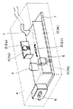
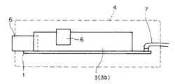
本発明の実施の一形態について、図面に基づいて説明すれば、以下の通りである。図1は、本実施形態に係る電子部品の放熱装置としてのACアダプタの概略の構成を示す透視斜視図である。また、図2は、上記ACアダプタの側面図である。
【0029】
上記ACアダプタは、プリント基板1(回路基板)と、発熱電子部品2と、放熱板3と、筐体4と、ACインレット5と、金属クリップ6と、出力ハーネス7と、電解コンデンサ8とを備えている。
【0030】
プリント基板1には、図示しない回路パターンが形成されている。発熱電子部品2は、プリント基板1の回路パターンに半田付け等で接続されることにより、プリント基板1に実装されるものであり、その動作時に発熱する。図1では、発熱電子部品2の例として、ダイオード等からなる部品2a・2bと、基板面に対して平行に延びるアキシャル形状の部品2cとを図示している。
【0031】
放熱板3は、発熱電子部品2にて発生した熱を外部に放出するものであり、例えば熱伝導に優れたアルミニウムや銅等からなる板状のものである。図1では、放熱板3の例として、放熱板3a・3bを図示している。放熱板3aは、部品2aとビス(図示せず)等で固定され、部品2aにて発生した熱を放熱する。放熱板3bは、部品2bと金属クリップ6で固定され、部品2bにて発生した熱を放熱する。
【0032】
放熱板3a・3bは、プリント基板1に対してそれぞれ垂直に設けられている。このうち、放熱板3aは、断面がL字状となるように折り曲げられている。一方、放熱板3bは、略長方形状となっている。これら放熱板3a・3bは、プリント基板1方向に突出した取付脚部(図示せず)をそれぞれ有している。プリント基板1に設けられた各取付孔(図示せず)に放熱板3a・3bの各取付脚部を挿入し、プリント基板1の裏側で折り曲げたり、半田付けすることで、放熱板3a・3bがプリント基板1に固定される。
【0033】
なお、本実施形態では、後述するように、発熱電子部品2およびプリント基板1が、放熱性(熱伝導性)を有する樹脂で形成された筐体4で覆われており、しかも、筐体4内部には上記樹脂が充填されているため、放熱板3を設けなくても発熱電子部品2にて発生した熱を筐体4を介して外部に放出することができる。つまり、本実施形態では、放熱板3は必須の構成要素ではない。しかし、放熱板3を設ければ、発熱電子部品2にて発生した熱を、放熱板3および筐体4を介して確実にかつ効率よく装置外部に放出することができる。
【0034】
ACインレット5は、ACアダプタの入力部である。金属クリップ6は、放熱板3bと部品2bとを固定するための弾力性のある金属性のクリップである。なお、放熱板3を設けない場合には、この金属クリップ6は不要である。出力ハーネス7は、ACアダプタの出力部である。電解コンデンサ8は、電荷を蓄積するものであるが、その寿命は一般的に短いものとなっている。
【0035】
筐体4は、発熱電子部品2およびプリント基板1を覆うものであり、本実施形態では、略直方体形状で形成されている。そして、この筐体4は、発熱電子部品2から発生する熱を外部に放出する樹脂で形成されている。しかも、筐体4内部には、当該樹脂が充填されている。
【0036】
上記樹脂は、熱伝導率の高い樹脂で構成されている。より具体的には、上記樹脂は、熱伝導率が例えば0.3W/m・kのウレタン樹脂やエポキシ樹脂で構成されている。これらの樹脂は、空気の熱伝導率が0.024W/m・kであることを考慮すると、空気よりも熱伝導率の高い樹脂で構成されていると言うことができる。また、上記樹脂は、プリント基板1よりも熱伝導率が高い樹脂で構成されていてもよい。
【0037】
本実施形態のACアダプタを製造する場合は、まず、プリント基板1に発熱電子部品2、電解コンデンサ8および必要に応じて放熱板3を取り付ける。なお、放熱板3を設ける場合は、発熱電子部品2と放熱板3とをビスや金属クリップ6で固定する。そして、プリント基板1にACインレット5および出力ハーネス7を取り付ける。
【0038】
続いて、上記各部品を取り付けたプリント基板1を、樹脂注型用の型(ケース形状)の内部に入れ、この型内に上記のウレタン樹脂またはエポキシ樹脂を流し込む。そして、上記樹脂を硬化させ、その後、型を取り外すことで、樹脂が充填された筐体4でプリント基板1が覆われたACアダプタが完成する。
【0039】
以上のように、本実施形態では、ACアダプタの外装を熱伝導率の高い樹脂で覆い、しかも、内部を空洞にするのではなく、図1および図2に示すように、ACアダプタの内部に熱伝導率の高い樹脂を充填させている。これにより、落下、踏み付け等、外部からの衝撃や圧力を上記樹脂にて確実に吸収することができるので、衝撃等に起因してACアダプタが破損するのを防止することができる。しかも、上記樹脂を空気よりも熱伝導率の高い樹脂で形成しているので、発熱電子部品2から発生した熱を、樹脂からなる筐体4を介して外部に確実に放出することができる。
【0040】
また、上記樹脂が充填された筐体4は、発熱電子部品2およびプリント基板1を覆うことができる大きさであればよく、従来と同等の大きさを確保したり、あるいは、従来のケースの厚み分だけ筐体4を小さく形成することが可能である。したがって、筐体4を上記樹脂で形成しても、ACアダプタ自体が大型化することはなく、むしろ、ACアダプタの小型化を図ることができる。
【0041】
なお、熱伝導率の高い樹脂でプリント基板1を覆ったときには、プリント基板1上の発熱電子部品2および電解コンデンサ8がこの樹脂にて覆われるので、ACアダプタ内部の熱が、例えば発熱電子部品2における半田面温度の上昇を招いたり、電解コンデンサ8の寿命を早めたりするなど、発熱電子部品2および電解コンデンサ8に悪影響を与えることが懸念される。
【0042】
しかし、ACアダプタ内部の熱のこもりが、熱伝導率の高い上記樹脂を介してアダプタ外部に確実に逃げるので、発熱電子部品2への悪影響はほとんどないと考えられる。また、電解コンデンサ8のスペック範囲(例えば許容温度範囲)内で樹脂注型することで、電解コンデンサ8への悪影響をも回避することができると考えられる。
【0043】
〔実施の形態2〕
本発明のさらに他の実施の形態について、図面に基づいて説明すれば、以下の通りである。なお、実施の形態1と同一の構成には同一の部材番号を付記し、その説明を省略する。
【0044】
図3は、本実施形態に係るACアダプタの概略の構成を示す断面図である。本実施形態では、実施の形態1で説明した筐体4の代わりに、ケース10を用いている。
【0045】
ケース10は、発熱電子部品2およびプリント基板1を覆う筐体であり、ケース天面10aと、ケース底面10bとで構成されている。ケース天面10aおよびケース底面10bには、それぞれを互いにビス(図示せず)等で固定するための複数の取付孔(図示せず)が設けられている。
【0046】
また、ケース天面10aおよびケース底面10bの四隅には、プリント基板1を固定するための孔(図示せず)が設けられている。これらの孔にビス(図示せず)等を挿入して、ケース天面10aおよびケース底面10bとプリント基板1とが固定される構造となっている。
【0047】
また、ケース天面10aの内面には、当該内面に密着して取り付けられ、発熱電子部品2(同図では部品2b)を放熱板3(同図では放熱板3b)に圧接する圧接部11が設けられている。この圧接部11は、ケース天面10aの内面から上記圧設する方向に向かって突出し、発熱電子部品2を圧接する突出部11aと、突出部11aを支持する支持部11bとで構成されている。このような圧接部11が設けられていることにより、発熱電子部品2は、ケース10内では、プリント基板1上で圧接部11と放熱板3とにより支持されることになる。
【0048】
なお、圧接部11は、ケース天面10aと一体的に成形されるものであってもよい。また、圧接部11の形成位置は、発熱電子部品2を放熱板3に圧接することができる位置であれば、ケース天面10aの内面のいずれの位置でもよい。
【0049】
発熱電子部品2と放熱板3との固定方式としては、従来では上記両者を金属製クリップ等によって挟み込む方式や、ビス締めによる方式であったが、本実施形態では、ケース10内面の圧接部11によって、発熱電子部品2を放熱板3に圧接する方式を採用している。したがって、上記両者の固定に際し、従来のようなクリップやビス等を用いる必要がなく、ケース天面10aとケース底面10bとを貼り合わせるだけで、発熱電子部品2を放熱板3に固定することができる。その結果、従来のようなクリップ等による固定工程が不要となるので、装置の製造工程を簡略化して、装置の製造コストを低減することができるとともに、装置の製造期間を短縮することができる。
【0050】
ところで、本実施形態では、熱伝導性を有する部材で圧接部11を構成してもよい。そのような熱伝導性部材としては、アルミニウムや銅などの金属や、(空気よりも)熱伝導率の高い樹脂(例えばウレタン樹脂やエポキシ樹脂)などを考えることができる。
【0051】
この場合、当該圧接部11によって発熱電子部品2を放熱板3に圧接したときに、発熱電子部品2にて発生した熱が、放熱板3にて放熱されるのみならず、圧接部11を介してケース天面10aに伝達され、外部に放出される。したがって、ACアダプタにおける放熱効果をより高めることができる。また、発熱電子部品2にて発生した熱は、圧接部11を介して迅速にケース天面10aに伝達されるので、ケース10内に当該熱がこもり、他の回路部品(例えば電解コンデンサ8)に悪影響(寿命を低下させる)を与えるのを回避することができる。
【0052】
以上のことから、本実施形態のACアダプタは、以下のように表現することもできる。すなわち、本実施形態の電子部品の放熱装置としてのACアダプタは、発熱電子部品が設けられた回路基板(プリント基板1)と、上記回路基板上に設けられ、上記発熱電子部品を支持する支持体(放熱板3)と、上記発熱電子部品、上記回路基板および上記支持体を覆う筐体(ケース10)と、上記筐体内面に設けられ、上記発熱電子部品を上記支持体に圧接するとともに、上記発熱電子部品から発生する熱を外部に放出する圧接放熱部(圧接部11)とを備えている構成である。
【0053】
〔実施の形態3〕
本発明のさらに他の実施の形態について、図面に基づいて説明すれば、以下の通りである。なお、実施の形態1・2と同一の構成には同一の部材番号を付記し、その説明を省略する。
【0054】
図4は、本実施形態に係るACアダプタの概略の構成を示す断面図である。本実施形態では、実施の形態2の圧接部11(図3参照)の代わりに、放熱部12をケース10内面に設けている一方で、プリント基板1上の放熱板3を省いた構成となっている。
【0055】
放熱部12は、発熱電子部品2(同図では部品2b)を挟持することにより、発熱電子部品2から発生する熱を外部に放出するものであり、熱伝導率の高い例えばアルミニウムや銅などの金属製の金具や、ウレタン樹脂やエポキシ樹脂などの空気よりも熱伝導率の高い樹脂で形成されている。この放熱部12は、ケース天面10aをケース底面10bに被せたときに、放熱部12が発熱電子部品2を挟み込むことができるように、発熱電子部品2の方向に複数箇所突出して、ケース天面10aの内面に設けられている。
【0056】
より具体的には、放熱部12は、2本の腕部12a・12bと、支持部12cとで構成されている。支持部12cは、腕部12a・12bを支持するものであり、ケース天面10aの内面に沿った形状で形成されている。腕部12a・12bは、発熱電子部品2を挟持するものであり、それぞれ、支持部12cによる支持側から発熱電子部品2との接触側に向かうにつれて若干折り曲がった形状となっている。また、腕部12a・12bは、プリント基板1の基板面に対する発熱電子部品2を通る垂直面に対して互いに線対称となる形状で形成されており、発熱電子部品2と接触する部分の互いの距離は、発熱電子部品2の厚さとほぼ同じ距離となっている。
【0057】
このように、本実施形態では、熱伝導性の高い、複数箇所突出させた放熱部12をケース天面10aの裏側へ密着して取り付けているので、ケース天面10aとケース底面10bとを貼り合わせるだけで、放熱部12の複数箇所突出させた部分、すなわち、腕部12a・12bにて発熱電子部品2を挟み込み、放熱部12と発熱電子部品2とを固定することができる。
【0058】
したがって、プリント基板1上に放熱板を設置する工程や、当該放熱板と発熱電子部品2とを金属製のクリップやビスで固定する工程が必要ない。その結果、装置の製造工程を簡略化して、装置の製造コストを低減することができるとともに、装置の製造期間を短縮することができる。
【0059】
しかも、放熱部12は熱伝導率の高い材料で形成されているため、発熱電子部品2が発する熱は、放熱部12にて放熱されるのみならず、放熱部12を介してケース天面10aへも伝達され、ケース天面10aにて放熱される。つまり、放熱部12とケース天面10aとで放熱の役目を果たすことになる。したがって、ACアダプタにおける放熱効果をより高めることができる。また、発熱電子部品2にて発生した熱は、放熱部12を介して迅速にケース天面10aに伝達されるので、ケース10内に当該熱がこもり、他の回路部品(例えば電解コンデンサ8)に悪影響(寿命を低下させる)を与えるのを回避することができる。
【0060】
〔実施の形態4〕
本発明のさらに他の実施の形態について、図面に基づいて説明すれば、以下の通りである。なお、実施の形態1〜3と同一の構成には同一の部材番号を付記し、その説明を省略する。
【0061】
図5は、本実施形態に係るACアダプタの概略の構成を示す断面図である。本実施形態では、実施の形態2または3の構成において、発熱電子部品2にて発生し、発熱電子部品2から部品リード13を介して伝達される熱を外部に放出する放熱シート14(放熱部材)を、プリント基板1の裏面(発熱電子部品2の設置面とは反対側の面)と所定の空隙を介してケース10内に設けている。
【0062】
放熱シート14としては、柔らかく、絶縁性を有しており、熱伝導性が高く、厚みのあるものが好適であり、例えば、熱伝導率1.5W/m・kの低硬度放熱シリコーンゴムシート(富士高分子工業株式会社製)を用いることができる。そして、この放熱シート14には、プリント基板1の回路パターンに半田付け等された発熱電子部品2の部品リード13が突き刺されている。
【0063】
このように、プリント基板1上に取付けられた発熱電子部品2の部品リード13を放熱シート14に突き刺すことにより、発熱電子部品2から半田面に伝達された熱(半田面熱)は、部品リード13を介して放熱シート14へと伝達されるの。その結果、発熱電子部品2の半田面温度の上昇を抑制することができ、発熱電子部品2とプリント基板1との回路パターンとの導通を安定化させることができる。
【0064】
また、放熱シート14をプリント基板1の裏側(半田面)に密着させるのではなく、プリント基板1の裏面と所定の空隙を介してケース10内に設けているので、イミニティ試験において、プリント基板1の回路パターンにて形成されている放電ギャップをも活用することができる。
【0065】
つまり、イミニティ試験の1つとして、例えばACライン(1次)と2次間に高電圧を印加する雷サージがある。雷サージを行う場合、雷サージの該当ラインのパターンを、安全規格に合致する距離以上を取った放電パターンとするために、該当部分の基板レジストを無くし、高電圧の印加によって該当部分(放電ギャップ)で沿面放電させる。なお、該当部分にスリットを設けて空中放電とする場合もある。
【0066】
したがって、放熱シート14がプリント基板1に密着していると、イミニティ試験において、上記該当部分で放電しなくなり、放電ギャップが活用できなくなるが、本実施形態では、放熱シート14とプリント基板1との間に所定の空隙が形成されているので、上記該当部分で確実に放電させることができ、イミニティ試験でも放電ギャップを活用することができる。
【0067】
以上のことから、実施の形態2または3に適用される本実施形態のACアダプタは、以下の構成であるとも言うことができる。
【0068】
すなわち、電子部品の放熱装置としてのACアダプタは、発熱電子部品が設けられた回路基板(プリント基板1)と、上記回路基板上に設けられ、上記発熱電子部品から発生する熱を外部に放出する放熱部材(放熱板3)と、上記発熱電子部品、上記回路基板および上記放熱手段を覆う筐体(ケース10)とを備えた電子部品の放熱装置であって、上記筐体内面に設けられ、上記発熱電子部品を上記放熱部材に圧接する圧接部(圧接部11)と、上記筐体内に設けられ、上記発熱電子部品から部品リード13を介して伝達される熱を外部に放出する放熱部材(放熱シート14)とを備えている構成である。
【0069】
また、電子部品の放熱装置としてのACアダプタは、発熱電子部品が設けられた回路基板(プリント基板1)と、上記発熱電子部品および上記回路基板を覆う筐体(ケース10)と、上記筐体内面に設けられ、上記発熱電子部品を挟持することにより、上記発熱電子部品から発生する熱を外部に放出する放熱部(放熱部12)と、上記筐体内に設けられ、上記発熱電子部品から部品リード13を介して伝達される熱を外部に放出する放熱部材(放熱シート14)とを備えている構成である。
【0070】
以上では、実施の形態2または3に適用されることを前提として、本実施形態のACアダプタについて説明したが、放熱シート14を設ける本実施形態の構成は、ケース10の内面に圧接部11(図3参照)や放熱部12(図4参照)を設けない場合にも、勿論適用することが可能である。
【0071】
〔実施の形態5〕
本発明の他の実施の形態について、図面に基づいて説明すれば、以下の通りである。なお、実施の形態1〜4と同一の構成には同一の部材番号を付記し、その説明を省略する。
【0072】
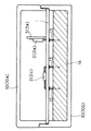
図6は、本実施形態に係るACアダプタ内部のプリント基板1上の概略の構成を示す斜視図である。また、図7は、プリント基板1の側面図である。なお、本実施形態では、発熱電子部品2および放熱板3が形成されたプリント基板1を、実施の形態2〜4と同様のケース10(図3〜図5参照)で覆っているが、図6では、そのケース10の図示を省略している。
【0073】
本実施形態では、実施の形態2ないし4のいずれかの構成において、アキシャル形状の発熱電子部品2(部品2c)とプリント基板1との間に、部品2cから発生する熱を外部に放出する放熱板3c(放熱部材)が設けられている。
【0074】
放熱板3cは、例えばアルミニウムや銅などの熱伝導率の高い金属からなる直方体型の平板放熱板である。この放熱板3cには、プリント基板1と部品2cとを結ぶ配線が通るための部品用孔20と、放熱板3cをプリント基板1に固定するための固定用孔21(図7参照)とが設けられている。この固定用孔21にビス22を挿入し、プリント基板1の裏側(放熱板3cの設置面とは反対側)からナット23で締め付けることにより、放熱板3cがプリント基板1上に密着して固定される。
【0075】
本実施形態の構成によれば、部品2cから発生する熱は、プリント基板1と反対側の空気中のみならず、熱伝導率の高い放熱板3cを介してプリント基板1に確実に伝導される。したがって、放熱板3cを設けずに、空気中もしくはプリント基板1へ直接放熱を行う従来に比べて、放熱効果を上げることができる。また、部品2cとプリント基板1との間の位置に放熱板3cを設けているので、放熱板3cをプリント基板1の基板面に立設する構成と比べても、プリント基板1への放熱効率を上げることができる。したがって、上記位置に放熱板3cを設ける本実施形態の構成によれば、部品2cの温度上昇をある程度抑え、半田面温度が急激に上昇するのを回避することができる。
【0076】
以上のことから、実施の形態2ないし4のいずれかに適用される本実施形態のACアダプタは、以下の構成であるとも言うことができる。
【0077】
すなわち、電子部品の放熱装置としてのACアダプタは、発熱電子部品が設けられた回路基板(プリント基板1)と、上記回路基板上に設けられ、上記発熱電子部品から発生する熱を外部に放出する第1の放熱部材(放熱板3a・3b)と、上記発熱電子部品、上記回路基板および上記第1の放熱部材を覆う筐体(ケース10)とを備えた電子部品の放熱装置であって、上記筐体内面に設けられ、上記発熱電子部品を上記第1の放熱部材に圧接する圧接部(圧接部11)と、上記筐体内に設けられ、上記発熱電子部品から部品リード13を介して伝達される熱を外部に放出する第2の放熱部材(放熱シート14)と、上記回路基板の基板面に対して平行に延びるアキシャル形状の発熱電子部品(部品2c)と上記回路基板との間に設けられ、上記アキシャル形状の発熱電子部品から発生する熱を外部に放出する第3の放熱部材(放熱板3c)とを備えている構成である。なお、上記第2の放熱部材(放熱シート14)は、構成要件として含んでいても、含んでいなくてもよい。
【0078】
また、電子部品の放熱装置としてのACアダプタは、発熱電子部品が設けられた回路基板(プリント基板1)と、上記発熱電子部品および上記回路基板を覆う筐体(ケース10)と、上記筐体内面に設けられ、上記発熱電子部品を挟持することにより、上記発熱電子部品から発生する熱を外部に放出する放熱部(放熱部12)と、上記筐体内に設けられ、上記発熱電子部品から部品リード13を介して伝達される熱を外部に放出する第2の放熱部材(放熱シート14)と、上記回路基板の基板面に対して平行に延びるアキシャル形状の発熱電子部品(部品2c)と上記回路基板との間に設けられ、上記アキシャル形状の発熱電子部品から発生する熱を外部に放出する第3の放熱部材(放熱板3c)とを備えている構成である。なお、上記第2の放熱部材(放熱シート14)は、構成要件として含んでいても、含んでいなくてもよい。
【0079】
以上では、実施の形態2ないし4のいずれかに適用されることを前提として、本実施形態のACアダプタについて説明したが、放熱板3cを設ける本実施形態の構成は、ケース10の内面に圧接部11(図3参照)や放熱部12(図4参照)を設けない場合にも、勿論適用することが可能である。
【0080】
〔実施の形態6〕
本発明のさらに他の実施の形態について、図面に基づいて説明すれば、以下の通りである。なお、実施の形態1〜5と同一の構成には同一の部材番号を付記し、その説明を省略する。
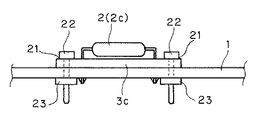
【0081】
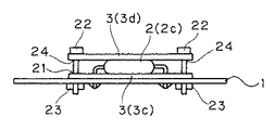
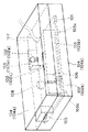
図8は、本実施形態に係るACアダプタ内部のプリント基板1上の概略の構成を示す斜視図である。また、図9は、プリント基板1の側面図である。なお、本実施形態では、発熱電子部品2および放熱板3が形成されたプリント基板1を、実施の形態2〜5と同様のケース10(図3〜図5参照)で覆っているが、図8では、そのケース10の図示を省略している。
【0082】
本実施形態では、実施の形態2ないし4のいずれかの構成において、部品2cに対してプリント基板1とは反対側に、放熱板3d(放熱部材)を設けている。つまり、本実施形態では、アキシャル形状の発熱電子部品2(部品2c)を挟んで、プリント基板1側とその反対側との両方に、互いに対向するように放熱板3c・3dを設けている。
【0083】
放熱板3dは、部品2cから発生する熱を外部に放出するものであり、放熱板3cとほぼ同様の構成である。すなわち、放熱板3dは、例えばアルミニウムや銅などの熱伝導率の高い金属からなる直方体型の平板放熱板である。この放熱板3dには、放熱板3dをプリント基板1に固定するための固定用孔24(図9参照)が設けられている。放熱板3dの固定用孔24と放熱板3cの固定用孔21とにビス22を挿入し、放熱板3d・3c間に所定の隙間を確保しながらプリント基板1の裏側(放熱板3cの設置面とは反対側)からナット23で締め付けることにより、部品2cを間に挟んだ状態で放熱板3c・3dがプリント基板1に固定される。
【0084】
本実施形態の構成によれば、部品2cから発生する熱は、熱伝導率の高い放熱板3cを介してプリント基板1に確実に伝達されるだけでなく、熱伝導率の高い放熱板3dを介してプリント基板1と反対側の空気中にも放出される。したがって、プリント基板1側にのみ放熱板3cを設ける実施の形態5の構成に比べて、さらに放熱効果を上げることができる。その結果、実施の形態5の構成による効果をより確実に得ることができる。
【0085】
以上のことから、実施の形態2ないし4のいずれかに適用される本実施形態のACアダプタは、以下の構成であるとも言うことができる。
【0086】
すなわち、電子部品の放熱装置としてのACアダプタは、発熱電子部品が設けられた回路基板(プリント基板1)と、上記回路基板上に設けられ、上記発熱電子部品から発生する熱を外部に放出する第1の放熱部材(放熱板3a・3b)と、上記発熱電子部品、上記回路基板および上記第1の放熱部材を覆う筐体(ケース10)とを備えた電子部品の放熱装置であって、上記筐体内面に設けられ、上記発熱電子部品を上記第1の放熱部材に圧接する圧接部(圧接部11)と、上記筐体内に設けられ、上記発熱電子部品から部品リード13を介して伝達される熱を外部に放出する第2の放熱部材(放熱シート14)と、上記回路基板の基板面に対して平行に延びるアキシャル形状の発熱電子部品を挟んで、上記回路基板側とその反対側との両方に設けられる第3の放熱部材(放熱板3c・3d)とをさらに備えている構成である。なお、上記第2の放熱部材(放熱シート14)は、構成要件として含んでいても、含んでいなくてもよい。
【0087】
また、電子部品の放熱装置としてのACアダプタは、発熱電子部品が設けられた回路基板(プリント基板1)と、上記発熱電子部品および上記回路基板を覆う筐体(ケース10)と、上記筐体内面に設けられ、上記発熱電子部品を挟持することにより、上記発熱電子部品から発生する熱を外部に放出する放熱部(放熱部12)と、上記筐体内に設けられ、上記発熱電子部品から部品リード13を介して伝達される熱を外部に放出する第2の放熱部材(放熱シート14)と、上記回路基板の基板面に対して平行に延びるアキシャル形状の発熱電子部品(部品2c)を挟んで、上記回路基板側とその反対側との両方に設けられ、上記アキシャル形状の発熱電子部品から発生する熱を外部に放出する第3の放熱部材(放熱板3c・3d)とを備えている構成である。なお、上記第2の放熱部材(放熱シート14)は、構成要件として含んでいても、含んでいなくてもよい。
【0088】
以上では、実施の形態2ないし4のいずれかに適用されることを前提として、本実施形態のACアダプタについて説明したが、放熱板3c・3dを設ける本実施形態の構成は、ケース10の内面に圧接部11(図3参照)や放熱部12(図4参照)を設けない場合にも、勿論適用することが可能である。
【0089】
【発明の効果】
本発明の電子部品の放熱装置によれば、発熱電子部品およびそれが設けられた回路基板が、放熱性を有する樹脂にて形成される筐体にて覆われ、しかも、筐体内部に上記樹脂が充填されている。これにより、落下等による外部からの衝撃や圧力が装置に加わったとしても、そのような衝撃等を当該樹脂にて確実に吸収することができる。したがって、外的な衝撃等による装置の破損を防止することができるとともに、装置内部の発熱電子部品および回路基板を確実に保護することができるという効果を奏する。
【0090】
また、本発明によれば、回路基板および放熱手段を覆う筐体の内面には、回路基板上の発熱電子部品を放熱部材に圧接する圧接部材が設けられているので、装置の製造にあたり、発熱電子部品と放熱部材とを予めビスやクリップ等で固定する必要がなくなる。したがって、装置の製造工程を簡略化して、装置の製造コストの低減、製造期間の短縮化を図ることができるという効果を奏する。
【0091】
また、本発明によれば、発熱電子部品および回路基板を覆う筐体の内面には、回路基板上の発熱電子部品を挟持するように放熱部が設けられているので、この放熱部は、放熱機能のみならず、当該放熱部と発熱電子部品とを固定する機能をも有する。したがって、回路基板上に放熱部材を設けたり、筐体内面の放熱部と回路基板上の発熱電子部品とをビスやクリップなどで固定する必要もない。その結果、装置の製造工程を簡略化して、装置の製造コストの低減、製造期間の短縮化を図ることができるという効果を奏する。
【0092】
また、本発明によれば、回路基板上の発熱電子部品にて発生する熱は、発熱電子部品の部品リードを介して放熱部材に伝達され、当該放熱部材にて外部に放出される。これにより、発熱電子部品にて発生した熱が半田面に蓄積されず、部品リードを介して放熱部材へと伝達される。その結果、発熱電子部品の半田面温度の上昇を抑制して、発熱電子部品と回路基板との導通状態を安定化することができるという効果を奏する。
【0093】
また、本発明によれば、アキシャル形状の発熱電子部品と回路基板との間に放熱部材が設けられている。これにより、上記発熱電子部品から発生する熱は、放熱部材を介して回路基板に確実に伝達される。したがって、放熱部材を基板面に立設する場合に比べて、回路基板への放熱効率を上げることができ、上記発熱電子部品の温度上昇をある程度抑えることができるという効果を奏する。
【0094】
また、上記アキシャル形状の発熱電子部品を挟んで、回路基板側とその反対側との両方に放熱部材を設ける構成とすれば、一方の放熱部材による回路基板への放熱効率のみならず、他方の放熱部材による空気中への放熱効率も上げることができる。これにより、上記発熱電子部品の温度上昇を大幅に抑えることができるという効果を奏する。
【図面の簡単な説明】
【図1】本発明の実施の一形態に係るACアダプタの概略の構成を示す透視斜視図である。
【図2】上記ACアダプタの概略の構成を示す側面図である。
【図3】本発明の他の実施の形態に係るACアダプタの概略の構成を示す断面図である。
【図4】本発明のさらに他の実施の形態に係るACアダプタの概略の構成を示す断面図である。
【図5】本発明のさらに他の実施の形態に係るACアダプタの概略の構成を示す断面図である。
【図6】本発明のさらに他の実施の形態に係るACアダプタの概略の構成を示す斜視図である。
【図7】上記ACアダプタを基板側面から見たときの側面図である。
【図8】本発明のさらに他の実施の形態に係るACアダプタの概略の構成を示す斜視図である。
【図9】上記ACアダプタを基板側面から見たときの側面図である。
【図10】従来のACアダプタの概略の構成を示す斜視図である。
【符号の説明】
1 プリント基板(回路基板)
2 発熱回路部品
2a 部品(発熱回路部品)
2b 部品(発熱回路部品)
2c 部品(発熱回路部品、アキシャル形状の部品)
3、3a、3b、3d 放熱板(放熱部材)
4 筐体
10 ケース(筐体)
11 圧接部
12 放熱部
13 部品リード
14 放熱シート(放熱部材)[0001]
TECHNICAL FIELD OF THE INVENTION
The present invention relates to a heat radiating device for an electronic component that emits heat generated by a heat-generating electronic component such as a diode provided on a circuit board to the outside.
[0002]
[Prior art]
2. Description of the Related Art Conventionally, an electronic device such as an AC adapter includes a heat-generating electronic component inside the AC adapter, and the heat generated by the heat-generating electronic component is released to the outside by, for example, a radiator plate. 1). A conventional AC adapter having such a structure will be specifically described below.
[0003]
FIG. 10 shows a schematic configuration of a conventional AC adapter including
[0004]
A circuit pattern (not shown) is formed on the printed
[0005]
The
[0006]
The
[0007]
The
[0008]
Holes (not shown) for fixing the printed
[0009]
AC
[0010]
As described above, in the conventional AC adapter, since the
[0011]
[Patent Document 1]
JP-A-9-13070 (published May 16, 1997)
[0012]
[Problems to be solved by the invention]
However, the configuration of the above-described conventional AC adapter has the following problems.
[0013]
(1) When an external impact or pressure is applied to the AC adapter, such as when the AC adapter is dropped, the AC adapter may be damaged if the
[0014]
(2) Before the case
[0015]
(3) When the heat-generating
[0016]
(4) Of the heat-generating
[0017]
The present invention has been made in order to solve the above problems, and an object of the present invention is to prevent damage to the device due to an external impact or the like without increasing the size of the device, and to ensure the inside of the device. An object of the present invention is to provide a heat dissipation device for electronic components that can be protected.
[0018]
It is another object of the present invention to provide a heat radiating device for an electronic component, which simplifies the manufacturing process of the device, reduces the manufacturing cost, and shortens the manufacturing period.
[0019]
Still another object of the present invention is to provide a heat radiating device for an electronic component capable of radiating heat generated in the heat generating electronic component while stabilizing a conduction state between the heat generating electronic component and a printed circuit board.
[0020]
Still another object of the present invention is to provide a heat radiating device for an electronic component that can efficiently radiate heat from an axially-shaped heat generating electronic component.
[0021]
[Means for Solving the Problems]
According to the present invention, the heat-generating electronic component and the circuit board on which the heat-generating electronic component is provided are covered with the housing. This housing is formed of a resin having a heat radiation property (for example, a resin having a higher thermal conductivity than air), and further, since the inside of the housing is filled with the above-mentioned resin, the housing may be exposed to the outside due to a drop or the like. Even if an impact or pressure is applied to the device, such an impact or the like can be reliably absorbed by the resin. Therefore, damage to the device due to an external impact or the like can be prevented, and the heat-generating electronic components and the circuit board inside the device can be reliably protected.
[0022]
Further, the housing filled with the resin only needs to be large enough to cover the heat-generating electronic components and the circuit board, and can be formed in a size equal to or smaller than that of the related art. Therefore, the size of the device itself does not increase.
[0023]
Further, according to the present invention, the press-contact portion for pressing the heat-generating electronic components on the circuit board to the heat-dissipating member is provided on the inner surface of the housing covering the circuit board and the heat-dissipating means. It is not necessary to fix the electronic component and the heat radiating member with screws or clips in advance. Therefore, since such a fixing step can be omitted and the manufacturing process of the device can be simplified, the manufacturing cost of the device can be reduced and the manufacturing period can be shortened.
[0024]
Further, according to the present invention, since the heat radiating portion is provided on the inner surface of the housing covering the heat generating electronic component and the circuit board so as to sandwich the heat generating electronic component on the circuit board, the heat radiating portion is provided with the heat radiating portion. It has not only the function but also the function of fixing the heat radiating part and the heat-generating electronic component by sandwiching. Therefore, there is no need to provide a heat radiating member on the circuit board or to fix the heat radiating portion on the inner surface of the housing and the heat-generating electronic components on the circuit board with screws or clips. Therefore, since such a fixing step can be omitted and the manufacturing process of the device can be simplified, the manufacturing cost of the device can be reduced and the manufacturing period can be shortened.
[0025]
Further, according to the present invention, the heat generated by the heat-generating electronic components on the circuit board is transmitted to the heat radiating member via the component leads of the heat-generating electronic component, and is radiated to the outside by the heat radiating member. Thus, for example, even when the heat-generating electronic component is electrically connected to the circuit pattern of the circuit board by soldering, the heat generated by the heat-generating electronic component is not accumulated on the solder surface, and is radiated through the component leads. It is transmitted to the member. As a result, it is possible to suppress an increase in the temperature of the solder surface of the heat-generating electronic component and to stabilize the conduction state between the heat-generating electronic component and the circuit board.
[0026]
Further, according to the present invention, the circuit board is provided with an axially-shaped heat-generating electronic component extending parallel to the board surface, and is provided between the heat-generating electronic component and the circuit board (for example, facing the board surface). (A flat plate-shaped heat dissipating member). Thus, the heat generated from the heat-generating electronic component is reliably transmitted to the circuit board via the heat radiating member. Therefore, compared with the case where the heat radiating member is provided upright on the board surface, the heat radiating efficiency to the circuit board can be increased, and the temperature rise of the heat-generating electronic component can be suppressed to some extent.
[0027]
In addition, if the heat-generating electronic components having the axial shape are interposed, and the heat-dissipating members are provided on both the circuit board side and the opposite side, not only the heat-dissipating efficiency to the circuit board by one heat-dissipating member but also the other The efficiency of heat radiation into the air by the heat radiation member can also be improved. As a result, the temperature rise of the heat-generating electronic component can be significantly suppressed.
[0028]
BEST MODE FOR CARRYING OUT THE INVENTION
[Embodiment 1]
One embodiment of the present invention will be described below with reference to the drawings. FIG. 1 is a transparent perspective view showing a schematic configuration of an AC adapter as a heat radiating device for an electronic component according to the present embodiment. FIG. 2 is a side view of the AC adapter.
[0029]
The AC adapter includes a printed circuit board 1 (circuit board), a heat-generating
[0030]
A circuit pattern (not shown) is formed on the printed
[0031]
The
[0032]
The
[0033]
In the present embodiment, as will be described later, the heat-generating
[0034]
The AC inlet 5 is an input unit of the AC adapter. The
[0035]
The housing 4 covers the heat-generating
[0036]
The resin is made of a resin having high thermal conductivity. More specifically, the resin is made of a urethane resin or an epoxy resin having a thermal conductivity of, for example, 0.3 W / mk. Considering that the thermal conductivity of air is 0.024 W / m · k, these resins can be said to be composed of resins having higher thermal conductivity than air. Further, the resin may be made of a resin having a higher thermal conductivity than the printed
[0037]
When manufacturing the AC adapter according to the present embodiment, first, the heat-generating
[0038]
Subsequently, the printed
[0039]
As described above, in the present embodiment, the exterior of the AC adapter is covered with a resin having a high thermal conductivity, and the interior is not hollow, but as shown in FIG. 1 and FIG. Filled with resin with high thermal conductivity. This makes it possible to reliably absorb the external impact and pressure such as dropping and stepping on the resin, thereby preventing the AC adapter from being damaged due to the impact or the like. Moreover, since the resin is formed of a resin having higher thermal conductivity than air, the heat generated from the heat-generating
[0040]
The housing 4 filled with the resin only needs to be large enough to cover the heat-generating
[0041]
When the printed
[0042]
However, since the heat build-up inside the AC adapter surely escapes to the outside of the adapter via the resin having a high thermal conductivity, it is considered that the heat-generating
[0043]
[Embodiment 2]
The following will describe still another embodiment of the present invention with reference to the drawings. The same components as those of the first embodiment are denoted by the same reference numerals, and description thereof will be omitted.
[0044]
FIG. 3 is a cross-sectional view illustrating a schematic configuration of the AC adapter according to the present embodiment. In the present embodiment, a
[0045]
The
[0046]
Further, holes (not shown) for fixing the printed
[0047]
A
[0048]
The
[0049]
Conventionally, the method of fixing the heat-generating
[0050]
By the way, in the present embodiment, the
[0051]
In this case, when the heat-generating
[0052]
From the above, the AC adapter of the present embodiment can also be expressed as follows. That is, the AC adapter as the heat radiating device of the electronic component according to the present embodiment includes a circuit board (printed board 1) provided with the heat-generating electronic component, and a support member provided on the circuit board and supporting the heat-generating electronic component. (Heat radiating plate 3), a housing (case 10) covering the heat-generating electronic components, the circuit board, and the support, and provided on the inner surface of the housing to press the heat-generating electronic components against the support. The heat dissipating part (pressing part 11) for releasing the heat generated from the heat-generating electronic component to the outside is provided.
[0053]
[Embodiment 3]
The following will describe still another embodiment of the present invention with reference to the drawings. The same components as those of the first and second embodiments are denoted by the same reference numerals, and the description thereof will be omitted.
[0054]
FIG. 4 is a cross-sectional view illustrating a schematic configuration of the AC adapter according to the present embodiment. In the present embodiment, instead of the pressure contact portion 11 (see FIG. 3) of the second embodiment, the
[0055]
The
[0056]
More specifically, the
[0057]
As described above, in the present embodiment, the
[0058]
Therefore, there is no need for a step of installing a heat sink on the printed
[0059]
Moreover, since the
[0060]
[Embodiment 4]
The following will describe still another embodiment of the present invention with reference to the drawings. The same components as those in the first to third embodiments are denoted by the same reference numerals, and description thereof will be omitted.
[0061]
FIG. 5 is a sectional view illustrating a schematic configuration of the AC adapter according to the present embodiment. In the present embodiment, in the configuration of the second or third embodiment, a heat radiating sheet 14 (a heat radiating member) that radiates heat generated in the heat generating
[0062]
The
[0063]
Thus, by piercing the
[0064]
Further, since the
[0065]
That is, as one of the immunity tests, for example, there is a lightning surge for applying a high voltage between the AC line (primary) and the secondary. When performing a lightning surge, in order to make the pattern of the applicable line of the lightning surge a discharge pattern that is longer than the distance conforming to the safety standards, the substrate resist in the relevant part is removed, and the relevant part (discharge gap ) To cause surface discharge. In some cases, a slit is provided in the corresponding portion to cause air discharge.
[0066]
Therefore, if the
[0067]
From the above, it can be said that the AC adapter of the present embodiment applied to the second or third embodiment has the following configuration.
[0068]
That is, an AC adapter as a heat radiating device for an electronic component is provided on a circuit board (printed board 1) on which a heat-generating electronic component is provided, and is provided on the circuit board, and radiates heat generated from the heat-generating electronic component to the outside. A heat radiating device for an electronic component, comprising: a heat radiating member (a heat radiating plate 3); and a housing (a case 10) covering the heat-generating electronic component, the circuit board, and the heat radiating means, provided on an inner surface of the housing. A press-contact portion (press-contact portion 11) for pressing the heat-generating electronic component against the heat-dissipating member; and a heat-dissipating member provided in the housing and radiating heat transmitted from the heat-generating electronic component via component leads 13 to the outside. And a heat radiating sheet 14).
[0069]
An AC adapter as a heat radiating device for electronic components includes a circuit board (printed circuit board 1) on which heat-generating electronic components are provided, a housing (case 10) covering the heat-generating electronic components and the circuit board, A heat radiating portion (heat radiating portion 12) that is provided on the surface and radiates heat generated from the heat generating electronic component to the outside by sandwiching the heat generating electronic component; The heat dissipating member (heat dissipating sheet 14) that dissipates heat transmitted through the
[0070]
In the above, the AC adapter according to the present embodiment has been described on the assumption that the AC adapter is applied to the second or third embodiment. Of course, the present invention can also be applied to a case where the heat radiating section 12 (see FIG. 4) is not provided.
[0071]
[Embodiment 5]
The following will describe another embodiment of the present invention with reference to the drawings. Note that the same components as those in
[0072]
FIG. 6 is a perspective view showing a schematic configuration on the printed
[0073]
In the present embodiment, in any of the configurations of the second to fourth embodiments, the heat radiation that radiates the heat generated from the
[0074]
The
[0075]
According to the configuration of the present embodiment, heat generated from the
[0076]
From the above, it can be said that the AC adapter of this embodiment applied to any of
[0077]
That is, an AC adapter as a heat radiating device for an electronic component is provided on a circuit board (printed board 1) on which a heat-generating electronic component is provided, and is provided on the circuit board, and radiates heat generated from the heat-generating electronic component to the outside. A heat dissipating device for an electronic component, comprising: a first heat dissipating member (
[0078]
An AC adapter as a heat radiating device for electronic components includes a circuit board (printed circuit board 1) on which heat-generating electronic components are provided, a housing (case 10) covering the heat-generating electronic components and the circuit board, A heat radiating portion (heat radiating portion 12) that is provided on the surface and radiates heat generated from the heat generating electronic component to the outside by sandwiching the heat generating electronic component; A second heat-dissipating member (heat-dissipating sheet 14) for releasing heat transmitted through the
[0079]
In the above, the AC adapter according to the present embodiment has been described assuming that the AC adapter is applied to any of the second to fourth embodiments. Of course, the present invention can also be applied to a case where the unit 11 (see FIG. 3) and the heat radiating unit 12 (see FIG. 4) are not provided.
[0080]
[Embodiment 6]
The following will describe still another embodiment of the present invention with reference to the drawings. The same components as those in
[0081]
FIG. 8 is a perspective view showing a schematic configuration on the printed
[0082]
In this embodiment, in any of the configurations of the second to fourth embodiments, a
[0083]
The
[0084]
According to the configuration of the present embodiment, the heat generated from the
[0085]
From the above, it can be said that the AC adapter of this embodiment applied to any of
[0086]
That is, an AC adapter as a heat radiating device for an electronic component is provided on a circuit board (printed board 1) on which a heat-generating electronic component is provided, and is provided on the circuit board, and radiates heat generated from the heat-generating electronic component to the outside. A heat dissipating device for an electronic component, comprising: a first heat dissipating member (
[0087]
An AC adapter as a heat radiating device for electronic components includes a circuit board (printed circuit board 1) on which heat-generating electronic components are provided, a housing (case 10) covering the heat-generating electronic components and the circuit board, A heat radiating portion (heat radiating portion 12) that is provided on the surface and radiates heat generated from the heat generating electronic component to the outside by sandwiching the heat generating electronic component; A second heat-dissipating member (heat-dissipating sheet 14) that radiates heat transmitted through the
[0088]
In the above, the AC adapter according to the present embodiment has been described on the assumption that the AC adapter is applied to any of
[0089]
【The invention's effect】
According to the heat radiating device for an electronic component of the present invention, the heat-generating electronic component and the circuit board on which the heat-generating electronic component is provided are covered with a casing formed of a resin having a heat radiation property, and the resin is placed inside the casing. Is filled. Accordingly, even if an external impact or pressure due to a drop or the like is applied to the apparatus, such an impact or the like can be reliably absorbed by the resin. Therefore, it is possible to prevent the device from being damaged due to an external impact or the like, and it is possible to surely protect the heat-generating electronic components and the circuit board inside the device.
[0090]
Further, according to the present invention, since the press-contact member for pressing the heat-generating electronic components on the circuit board against the heat-dissipating member is provided on the inner surface of the casing that covers the circuit board and the heat-dissipating means, It is not necessary to fix the electronic component and the heat radiating member with screws or clips in advance. Therefore, there is an effect that the manufacturing process of the device can be simplified, the manufacturing cost of the device can be reduced, and the manufacturing period can be shortened.
[0091]
Further, according to the present invention, since the heat radiating portion is provided on the inner surface of the housing covering the heat generating electronic component and the circuit board so as to sandwich the heat generating electronic component on the circuit board, the heat radiating portion is provided with the heat radiating portion. It has not only the function but also the function of fixing the heat radiation part and the heat-generating electronic component. Therefore, there is no need to provide a heat radiating member on the circuit board or to fix the heat radiating portion on the inner surface of the housing and the heat-generating electronic components on the circuit board with screws or clips. As a result, there is an effect that the manufacturing process of the device can be simplified, the manufacturing cost of the device can be reduced, and the manufacturing period can be shortened.
[0092]
Further, according to the present invention, the heat generated by the heat-generating electronic components on the circuit board is transmitted to the heat radiating member via the component leads of the heat-generating electronic component, and is radiated to the outside by the heat radiating member. Thus, the heat generated by the heat-generating electronic component is not accumulated on the solder surface, but is transmitted to the heat radiation member via the component lead. As a result, it is possible to suppress an increase in the temperature of the soldering surface of the heat-generating electronic component, thereby stabilizing the conduction state between the heat-generating electronic component and the circuit board.
[0093]
Further, according to the present invention, the heat radiating member is provided between the axial-shaped heat-generating electronic component and the circuit board. Thus, the heat generated from the heat-generating electronic component is reliably transmitted to the circuit board via the heat radiating member. Therefore, compared with the case where the heat radiating member is provided upright on the board surface, the heat radiating efficiency to the circuit board can be improved, and the temperature rise of the heat-generating electronic component can be suppressed to some extent.
[0094]
In addition, if the heat-generating electronic components having the axial shape are interposed, and the heat-dissipating members are provided on both the circuit board side and the opposite side, not only the heat-dissipating efficiency to the circuit board by one heat-dissipating member but also the other The efficiency of heat radiation into the air by the heat radiation member can also be improved. Thereby, there is an effect that the temperature rise of the heat-generating electronic component can be significantly suppressed.
[Brief description of the drawings]
FIG. 1 is a perspective view showing a schematic configuration of an AC adapter according to an embodiment of the present invention.
FIG. 2 is a side view showing a schematic configuration of the AC adapter.
FIG. 3 is a cross-sectional view illustrating a schematic configuration of an AC adapter according to another embodiment of the present invention.
FIG. 4 is a cross-sectional view illustrating a schematic configuration of an AC adapter according to still another embodiment of the present invention.
FIG. 5 is a sectional view showing a schematic configuration of an AC adapter according to still another embodiment of the present invention.
FIG. 6 is a perspective view showing a schematic configuration of an AC adapter according to still another embodiment of the present invention.
FIG. 7 is a side view of the AC adapter when viewed from the side of the board.
FIG. 8 is a perspective view showing a schematic configuration of an AC adapter according to still another embodiment of the present invention.
FIG. 9 is a side view when the AC adapter is viewed from the side of the board.
FIG. 10 is a perspective view showing a schematic configuration of a conventional AC adapter.
[Explanation of symbols]
1 Printed circuit board (circuit board)
2 Heating circuit parts
2a parts (heating circuit parts)
2b parts (heating circuit parts)
2c parts (heating circuit parts, axial parts)
3, 3a, 3b, 3d Heat sink (heat sink)
4 Case
10. Case (housing)
11 Pressure welding part
12 Heat radiation part
13 Component lead
14. Heat dissipation sheet (heat dissipation member)
Claims (9)
上記発熱電子部品および上記回路基板を覆う筐体とを備え、
上記筐体は、上記発熱電子部品から発生する熱を外部に放出する樹脂で形成されており、上記筐体内部に当該樹脂が充填されていることを特徴とする電子部品の放熱装置。A circuit board on which heat-generating electronic components are provided;
A housing that covers the heat-generating electronic component and the circuit board,
The heat radiating device for an electronic component, wherein the housing is formed of a resin that emits heat generated from the heat-generating electronic component to the outside, and the resin is filled in the housing.
上記回路基板上に設けられ、上記発熱電子部品から発生する熱を外部に放出する放熱部材と、
上記発熱電子部品、上記回路基板および上記放熱手段を覆う筐体とを備えた電子部品の放熱装置であって、
上記筐体内面に設けられ、上記発熱電子部品を上記放熱部材に圧接する圧接部をさらに備えていることを特徴とする電子部品の放熱装置。A circuit board on which heat-generating electronic components are provided;
A heat dissipating member provided on the circuit board, for releasing heat generated from the heat generating electronic component to the outside,
A heat dissipating device for an electronic component, comprising: the heat generating electronic component, a housing that covers the circuit board and the heat dissipating means,
A heat dissipating device for an electronic component, further comprising a press-contact portion provided on an inner surface of the housing and pressing the heat-generating electronic component against the heat dissipating member.
上記発熱電子部品および上記回路基板を覆う筐体と、
上記筐体内面に設けられ、上記発熱電子部品を挟持することにより、上記発熱電子部品から発生する熱を外部に放出する放熱部とを備えていることを特徴とする電子部品の放熱装置。A circuit board on which heat-generating electronic components are provided;
A housing that covers the heat-generating electronic components and the circuit board;
A heat radiating device for an electronic component, comprising: a heat radiating portion provided on an inner surface of the housing and configured to radiate heat generated from the heat generating electronic component to the outside by sandwiching the heat generating electronic component.
上記発熱電子部品および上記回路基板を覆う筐体と、
上記筐体内に設けられ、上記発熱電子部品から部品リードを介して伝達される熱を外部に放出する放熱部材とを備えていることを特徴とする電子部品の放熱装置。A circuit board on which heat-generating electronic components are provided;
A housing that covers the heat-generating electronic components and the circuit board;
A heat radiating member provided in the housing and radiating heat transmitted from the heat-generating electronic component via a component lead to the outside.
上記発熱電子部品から発生する熱を外部に放出する放熱部材とを備え、
上記発熱電子部品は、上記回路基板の基板面に対して平行に延びるアキシャル形状の部品であり、
上記放熱部材は、上記アキシャル形状の発熱電子部品と上記回路基板との間に設けられていることを特徴とする電子部品の放熱装置。A circuit board on which heat-generating electronic components are provided;
A heat dissipating member that emits heat generated from the heat generating electronic component to the outside,
The heat-generating electronic component is an axial component that extends in parallel with the board surface of the circuit board,
The heat radiating device for an electronic component, wherein the heat radiating member is provided between the axial heat generating electronic component and the circuit board.
上記発熱電子部品から発生する熱を外部に放出する放熱部材とを備え、
上記発熱電子部品は、上記回路基板の基板面に対して平行に延びるアキシャル形状の部品であり、
上記放熱部材は、上記アキシャル形状の発熱電子部品を挟んで、上記回路基板側とその反対側との両方に設けられていることを特徴とする電子部品の放熱装置。A circuit board on which heat-generating electronic components are provided;
A heat dissipating member that emits heat generated from the heat generating electronic component to the outside,
The heat-generating electronic component is an axial component that extends in parallel with the board surface of the circuit board,
The heat radiating device for an electronic component, wherein the heat radiating member is provided on both the circuit board side and the opposite side with the axial heat generating electronic component interposed therebetween.
Priority Applications (1)
| Application Number | Priority Date | Filing Date | Title |
|---|---|---|---|
| JP2002326567A JP2004165251A (en) | 2002-11-11 | 2002-11-11 | Radiating device for electronic component |
Applications Claiming Priority (1)
| Application Number | Priority Date | Filing Date | Title |
|---|---|---|---|
| JP2002326567A JP2004165251A (en) | 2002-11-11 | 2002-11-11 | Radiating device for electronic component |
Publications (1)
| Publication Number | Publication Date |
|---|---|
| JP2004165251A true JP2004165251A (en) | 2004-06-10 |
Family
ID=32805455
Family Applications (1)
| Application Number | Title | Priority Date | Filing Date |
|---|---|---|---|
| JP2002326567A Pending JP2004165251A (en) | 2002-11-11 | 2002-11-11 | Radiating device for electronic component |
Country Status (1)
| Country | Link |
|---|---|
| JP (1) | JP2004165251A (en) |
Cited By (5)
| Publication number | Priority date | Publication date | Assignee | Title |
|---|---|---|---|---|
| KR101093142B1 (en) | 2011-08-25 | 2011-12-12 | (주)에코모바일 | A slim rectifier for outdoor type communication device |
| KR101846204B1 (en) * | 2016-11-29 | 2018-04-06 | 현대오트론 주식회사 | Elctronic control device having interior heat radiation fin |
| CN113490368A (en) * | 2021-07-07 | 2021-10-08 | 台达电子企业管理(上海)有限公司 | Power supply device and high-power lighting system |
| JP2022020761A (en) * | 2017-07-20 | 2022-02-01 | アモグリーンテック カンパニー リミテッド | Power relay assembly |
| JP2022146854A (en) * | 2021-03-22 | 2022-10-05 | 台達電子工業股▲ふん▼有限公司 | socket structure |
-
2002
- 2002-11-11 JP JP2002326567A patent/JP2004165251A/en active Pending
Cited By (8)
| Publication number | Priority date | Publication date | Assignee | Title |
|---|---|---|---|---|
| KR101093142B1 (en) | 2011-08-25 | 2011-12-12 | (주)에코모바일 | A slim rectifier for outdoor type communication device |
| KR101846204B1 (en) * | 2016-11-29 | 2018-04-06 | 현대오트론 주식회사 | Elctronic control device having interior heat radiation fin |
| JP2022020761A (en) * | 2017-07-20 | 2022-02-01 | アモグリーンテック カンパニー リミテッド | Power relay assembly |
| JP2022146854A (en) * | 2021-03-22 | 2022-10-05 | 台達電子工業股▲ふん▼有限公司 | socket structure |
| JP7225340B2 (en) | 2021-03-22 | 2023-02-20 | 台達電子工業股▲ふん▼有限公司 | socket structure |
| US11637395B2 (en) | 2021-03-22 | 2023-04-25 | Delta Electronics, Inc. | Socket structure |
| CN113490368A (en) * | 2021-07-07 | 2021-10-08 | 台达电子企业管理(上海)有限公司 | Power supply device and high-power lighting system |
| CN113490368B (en) * | 2021-07-07 | 2023-03-21 | 台达电子企业管理(上海)有限公司 | Power supply device and high-power lighting system |
Similar Documents
| Publication | Publication Date | Title |
|---|---|---|
| JP5388598B2 (en) | Element heat dissipation structure | |
| JP5936313B2 (en) | Electronic component mounting structure | |
| JP2002217343A (en) | Electronic device | |
| JP3711332B2 (en) | Electronics | |
| JP2006278941A (en) | Heat sink device and plug-in unit | |
| JP2010177404A (en) | Cooling structure for light-emitting device | |
| US20030021310A1 (en) | Method and apparatus for cooling electronic or opto-electronic devices | |
| US20080198557A1 (en) | Heat-dissipating module | |
| JP4207755B2 (en) | Electronic equipment | |
| JPH10313184A (en) | Heat-dissipating structure of electronic equipment | |
| CN112020266A (en) | Multipurpose radiator, manufacturing method thereof, board card and multipurpose radiator platform | |
| JP2004047311A (en) | Discharge lamp lighting device and projecting device using the same | |
| JP2004165251A (en) | Radiating device for electronic component | |
| JP2007019125A (en) | Electric power conversion device | |
| JP4452888B2 (en) | Electronic circuit equipment | |
| JPH11266090A (en) | Semiconductor device | |
| JP2009017624A (en) | Motor controller | |
| JPH11163564A (en) | Electronic apparatus and its manufacture | |
| JP2000252657A (en) | Heat dissipation unit for control apparatus | |
| JP2004031854A (en) | Heat radiation structure | |
| WO2023090102A1 (en) | Mounting board and electrical equipment having mounting board installed thereon | |
| WO2023085073A1 (en) | Mounting board, and electric apparatus equipped with mounting board | |
| KR20080004734A (en) | Radiating structure in exothermic element | |
| JPH09321467A (en) | Heat radiating structure for heat generating electronic part | |
| JP2012064705A (en) | Radiator attachment structure and electronic apparatus |