EP4580004A1 - Innenmagnetrotor und elektrische innenmagnetdrehmaschine - Google Patents
Innenmagnetrotor und elektrische innenmagnetdrehmaschine Download PDFInfo
- Publication number
- EP4580004A1 EP4580004A1 EP22931235.0A EP22931235A EP4580004A1 EP 4580004 A1 EP4580004 A1 EP 4580004A1 EP 22931235 A EP22931235 A EP 22931235A EP 4580004 A1 EP4580004 A1 EP 4580004A1
- Authority
- EP
- European Patent Office
- Prior art keywords
- magnet
- permanent magnet
- rotor
- housing hole
- permanent magnets
- Prior art date
- Legal status (The legal status is an assumption and is not a legal conclusion. Google has not performed a legal analysis and makes no representation as to the accuracy of the status listed.)
- Pending
Links
Images


Classifications
-
- H—ELECTRICITY
- H02—GENERATION; CONVERSION OR DISTRIBUTION OF ELECTRIC POWER
- H02K—DYNAMO-ELECTRIC MACHINES
- H02K1/00—Details of the magnetic circuit
- H02K1/06—Details of the magnetic circuit characterised by the shape, form or construction
- H02K1/22—Rotating parts of the magnetic circuit
- H02K1/27—Rotor cores with permanent magnets
- H02K1/2706—Inner rotors
- H02K1/272—Inner rotors the magnetisation axis of the magnets being perpendicular to the rotor axis
- H02K1/274—Inner rotors the magnetisation axis of the magnets being perpendicular to the rotor axis the rotor consisting of two or more circumferentially positioned magnets
- H02K1/2753—Inner rotors the magnetisation axis of the magnets being perpendicular to the rotor axis the rotor consisting of two or more circumferentially positioned magnets the rotor consisting of magnets or groups of magnets arranged with alternating polarity
- H02K1/276—Magnets embedded in the magnetic core, e.g. interior permanent magnets [IPM]
- H02K1/2766—Magnets embedded in the magnetic core, e.g. interior permanent magnets [IPM] having a flux concentration effect
-
- H—ELECTRICITY
- H02—GENERATION; CONVERSION OR DISTRIBUTION OF ELECTRIC POWER
- H02K—DYNAMO-ELECTRIC MACHINES
- H02K1/00—Details of the magnetic circuit
- H02K1/06—Details of the magnetic circuit characterised by the shape, form or construction
- H02K1/22—Rotating parts of the magnetic circuit
- H02K1/27—Rotor cores with permanent magnets
- H02K1/2706—Inner rotors
- H02K1/272—Inner rotors the magnetisation axis of the magnets being perpendicular to the rotor axis
- H02K1/274—Inner rotors the magnetisation axis of the magnets being perpendicular to the rotor axis the rotor consisting of two or more circumferentially positioned magnets
- H02K1/2753—Inner rotors the magnetisation axis of the magnets being perpendicular to the rotor axis the rotor consisting of two or more circumferentially positioned magnets the rotor consisting of magnets or groups of magnets arranged with alternating polarity
- H02K1/276—Magnets embedded in the magnetic core, e.g. interior permanent magnets [IPM]
-
- H—ELECTRICITY
- H02—GENERATION; CONVERSION OR DISTRIBUTION OF ELECTRIC POWER
- H02K—DYNAMO-ELECTRIC MACHINES
- H02K2213/00—Specific aspects, not otherwise provided for and not covered by codes H02K2201/00 - H02K2211/00
- H02K2213/03—Machines characterised by numerical values, ranges, mathematical expressions or similar information
-
- Y—GENERAL TAGGING OF NEW TECHNOLOGICAL DEVELOPMENTS; GENERAL TAGGING OF CROSS-SECTIONAL TECHNOLOGIES SPANNING OVER SEVERAL SECTIONS OF THE IPC; TECHNICAL SUBJECTS COVERED BY FORMER USPC CROSS-REFERENCE ART COLLECTIONS [XRACs] AND DIGESTS
- Y02—TECHNOLOGIES OR APPLICATIONS FOR MITIGATION OR ADAPTATION AGAINST CLIMATE CHANGE
- Y02T—CLIMATE CHANGE MITIGATION TECHNOLOGIES RELATED TO TRANSPORTATION
- Y02T10/00—Road transport of goods or passengers
- Y02T10/60—Other road transportation technologies with climate change mitigation effect
- Y02T10/64—Electric machine technologies in electromobility
Definitions
- Embodiments of the present invention relate to an interior magnet rotor and an interior magnet rotary electric machine including the same.
- each of the permanent magnets is formed in a rectangular parallelepiped shape.
- This permanent magnet is a brittle member and is likely to be chipped by an impact, and if a fragment comes off because of the chipping, the volume of the magnet reduces, leading to a decrease in the amount of magnetic flux and deterioration in properties. Further, if a fragment comes off because of chipping, the fallen fragment is caught in or clogs a gap in the synchronous machine, which causes a mechanically adverse effect such as the restriction of rotation or an electrically adverse effect such as a short circuit. Further, if chipping occurs and a fragment comes off after surface treatment is applied for rust prevention, the material is exposed, which may cause corrosion (generation of rust) from the chipped portion.
- the permanent magnet is formed in the shape having vertex portions (ridges), such as a substantially rectangular parallelepiped shape
- chamfering is performed at its four corners to remove the vertex portions and form slopes, thereby preventing chipping caused by contact between the vertex portions of magnets during the manufacture.
- a plurality of permanent magnets instead of a single permanent magnet are sometimes housed in a magnet hole of a rotor core, that is, the permanent magnet is practically divided into a plurality of pieces, whereby an eddy current generated in the permanent magnet is reduced.
- the plurality of permanent magnets are adjacent to and in contact with each other.
- the aforesaid chamfering is a work taking a lot of time and effort in the case where, for example, it is performed by barrel polishing or grinder polishing. Further, forming the slopes in advance using a die leads to an increase in the manufacturing cost.
- An object of the present invention is to provide an interior magnet rotor that achieves a reduction in a demagnetizing factor of its permanent magnet without causing an increase in an eddy current and without causing an increase in the risk of chipping of vertex portions in a plurality of permanent magnets housed in a row in a magnet housing hole.
- an interior magnet rotor includes: a rotor shaft extending in a rotation axis direction; a rotor core that has at least one magnet housing hole formed in each magnetic pole and sandwiched by a first wall and a second wall, and that is attached to the rotor shaft; and a plurality of permanent magnets housed in the magnet housing hole and arranged in a row in one direction in a cross section of the magnet housing hole, wherein the plurality of permanent magnets each have a substantially rectangular parallelepiped outer shape and have slopes formed over a longitudinal direction at two corners opposite to each other.
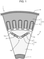
- FIG. 1 is a partial cross sectional view illustrating the structure of the interior magnet rotary electric machine 1 according to the embodiment.
- the interior magnet rotary electric machine 1 has the interior magnet rotor 10, a stator 30, and a frame 40.
- the stator 30 has a stator core 31 arranged on a radially outer side of a rotor core 12 with gap therebetween, and stator windings 32 wound around the stator core 31.
- the frame 40 houses the stator 30.
- the interior magnet rotor 10 has a rotor shaft 11, the rotor core 12 attached on the radially outer side of the rotor shaft 11, and a plurality of permanent magnets 20 housed in the rotor core 12.
- the permanent magnets 20 each have a first permanent magnet 21 and a second permanent magnet 22 arranged in series.
- FIG. 1 illustrates one magnetic pole 10a portion. Note that FIG. 1 illustrates, as an example, the case where the two permanent magnets 20 in the interior magnet rotor 10 are formed and arranged to make a pair, but this is not restrictive. For example, one of the permanent magnets 20 may form one magnetic pole.
- the feature of this embodiment relates to the plurality of permanent magnets of the permanent magnet 20 in the case where the permanent magnets 20 each have the plurality of permanent magnets arranged in series.
- the case where number of the plurality of permanent magnets that the permanent magnet 20 is two, first permanent magnet 21 and second permanent magnet 22, as illustrated in FIG. 1 will be described as an example, but they may be three permanent magnets or more.
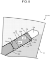
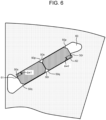
- FIG. 2 is a perspective view illustrating the permanent magnet 20 of the interior magnet rotor 10 according to the embodiment.
- FIG. 2 illustrates a state where the first permanent magnet 21 and the second permanent magnet 22 are arranged in a row.
- the first permanent magnet 21 has a substantially rectangular parallelepiped shape.
- the first permanent magnet 21 has four side faces, namely, a first side face 21a, a second side face 21b, a third side face 21c, and a fourth side face 21d each located along the longitudinal direction, that is, the axial direction of the rotor shaft 11.
- a first corner slope 21p is formed on a corner where the first side face 21a and the second side face 21b connect with each other.
- a second corner slope 21q is formed on a corner where the third side face 21c and the fourth side face 21d connect with each other.
- the first corner slope 21p makes a 45-degree angle with the first side face 21a and the second side face 21b.
- the second corner slope 21q makes a 45-degree angle with the third side face 21c and the fourth side face 21d.
- the first permanent magnet 21 and the second permanent magnet 22 are arranged with the first side face 21a of the first permanent magnet 21 and the first side face 22a of the second permanent magnet 22 facing the same direction, and with the second side face 21b of the first permanent magnet 21 and the third side face 22c of the second permanent magnet 22 facing and adjacent to each other. In other words, the first permanent magnet 21 and the second permanent magnet 22 are arranged in the same orientation.
- first corner slope 21p and the second corner slope 21q of the first permanent magnet 21 and the first corner slope 22p and the second corner slope 22q of the second permanent magnet 22 are each adjacent to any of the side faces. That is, corners not having the first corner slope 21p nor the second corner slope 21q of the first permanent magnet 21 and corners not having the first corner slope 22p nor the second corner slope 22q of the second permanent magnet 22 are not adjacent to each other.
Landscapes
- Engineering & Computer Science (AREA)
- Power Engineering (AREA)
- Permanent Field Magnets Of Synchronous Machinery (AREA)
Applications Claiming Priority (2)
| Application Number | Priority Date | Filing Date | Title |
|---|---|---|---|
| JP2022134141 | 2022-08-25 | ||
| PCT/JP2022/038530 WO2024042731A1 (ja) | 2022-08-25 | 2022-10-17 | 埋込磁石式回転子および埋込磁石式回転電機 |
Publications (2)
| Publication Number | Publication Date |
|---|---|
| EP4580004A1 true EP4580004A1 (de) | 2025-07-02 |
| EP4580004A4 EP4580004A4 (de) | 2026-04-01 |
Family
ID=88021751
Family Applications (1)
| Application Number | Title | Priority Date | Filing Date |
|---|---|---|---|
| EP22931235.0A Pending EP4580004A4 (de) | 2022-08-25 | 2022-10-17 | Innenmagnetrotor und elektrische innenmagnetdrehmaschine |
Country Status (4)
| Country | Link |
|---|---|
| US (1) | US20240072583A1 (de) |
| EP (1) | EP4580004A4 (de) |
| JP (1) | JP7346771B1 (de) |
| CN (1) | CN117941222A (de) |
Families Citing this family (2)
| Publication number | Priority date | Publication date | Assignee | Title |
|---|---|---|---|---|
| CN121058149A (zh) * | 2024-04-02 | 2025-12-02 | 烟台东星磁性材料股份有限公司 | 具有不规则多面体形状永磁体的转子 |
| DE102024119407A1 (de) * | 2024-07-09 | 2026-01-15 | Dr. Ing. H.C. F. Porsche Aktiengesellschaft | Befestigungsklammer und Rotorblechschnitt eines Elektromotors |
Family Cites Families (15)
| Publication number | Priority date | Publication date | Assignee | Title |
|---|---|---|---|---|
| US8525381B2 (en) * | 2008-11-19 | 2013-09-03 | Mitsubishi Electric Corporation | Rotor of electric motor and electric motor and ventilation fan and compressor |
| JP5328821B2 (ja) * | 2011-02-03 | 2013-10-30 | トヨタ自動車株式会社 | 回転電機用回転子 |
| KR101566047B1 (ko) * | 2011-03-29 | 2015-11-05 | 한양대학교 산학협력단 | 자속 집중형 영구자석 전동기 |
| JP5776275B2 (ja) * | 2011-03-31 | 2015-09-09 | Tdk株式会社 | 複合磁石構造体 |
| JP5936060B2 (ja) * | 2012-09-14 | 2016-06-15 | 株式会社デンソー | 回転電機のロータ |
| JP6110151B2 (ja) * | 2013-02-07 | 2017-04-05 | 本田技研工業株式会社 | 回転電機のロータ |
| JP5930994B2 (ja) * | 2013-03-22 | 2016-06-08 | 三菱電機株式会社 | 永久磁石埋込型電動機の回転子、圧縮機及び冷凍空調装置 |
| US9754719B2 (en) * | 2013-08-29 | 2017-09-05 | Nissan Motor Co., Ltd. | Cutting method and cutting device of manufacturing magnet piece forming magnet body for field pole to be arranged in rotating electric machine |
| JP5962632B2 (ja) * | 2013-11-15 | 2016-08-03 | 株式会社デンソー | 回転電機のロータ及びその製造方法 |
| JP2018164378A (ja) * | 2017-03-27 | 2018-10-18 | 本田技研工業株式会社 | Ipmロータ用磁石、ipmロータおよびipmロータ用磁石の製造方法 |
| CN110959244B (zh) * | 2017-08-01 | 2022-07-01 | 株式会社电装 | 电动机的磁产生装置、软磁性体铁芯及磁体的制造方法 |
| JP6852693B2 (ja) * | 2017-08-01 | 2021-03-31 | 株式会社デンソー | 電動機の磁気発生装置 |
| DE112018006694T5 (de) * | 2017-12-28 | 2020-09-10 | Denso Corporation | Rotierende elektrische Maschine |
| JP7594349B2 (ja) * | 2018-11-15 | 2024-12-04 | 株式会社デンソー | 回転電機 |
| JP7371361B2 (ja) * | 2019-06-20 | 2023-10-31 | 株式会社デンソー | 回転電機 |
-
2022
- 2022-10-17 JP JP2023520295A patent/JP7346771B1/ja active Active
- 2022-10-17 EP EP22931235.0A patent/EP4580004A4/de active Pending
- 2022-10-17 CN CN202280009180.2A patent/CN117941222A/zh active Pending
-
2023
- 2023-09-25 US US18/473,481 patent/US20240072583A1/en active Pending
Also Published As
| Publication number | Publication date |
|---|---|
| EP4580004A4 (de) | 2026-04-01 |
| JP7346771B1 (ja) | 2023-09-19 |
| JPWO2024042731A1 (de) | 2024-02-29 |
| US20240072583A1 (en) | 2024-02-29 |
| CN117941222A (zh) | 2024-04-26 |
Similar Documents
| Publication | Publication Date | Title |
|---|---|---|
| US7342338B2 (en) | Permanent magnet electric motor with reduced cogging torque | |
| US7042127B2 (en) | Permanent magnet embedded motor | |
| CN106165259B (zh) | 永磁体埋入型旋转电机 | |
| JP5537964B2 (ja) | 回転電機 | |
| US6717315B1 (en) | Permanent magnet type motor and method of producing permanent magnet type motor | |
| CN101461119B (zh) | 分割型定子铁心及其制造方法、定子铁心 | |
| JP6461381B2 (ja) | 回転電機の固定子、回転電機、および、回転電機の固定子の製造方法 | |
| US20120267975A1 (en) | Embedded permanent magnet electric motor | |
| EP4580004A1 (de) | Innenmagnetrotor und elektrische innenmagnetdrehmaschine | |
| JP5040988B2 (ja) | ステータおよびこのステータを備えるモータ | |
| JPWO2017090571A1 (ja) | モータおよびモータの製造方法 | |
| CN102754307A (zh) | 永久磁铁、用于马达的转子或定子、旋转电机 | |
| JP5313935B2 (ja) | 回転電機の固定子の製造方法および回転電機の固定子 | |
| US20130342065A1 (en) | Brushless motor and method for manufacturing brushless motor | |
| CN108496293B (zh) | 具有印刷的连接片的电工钢片 | |
| JPH06245419A (ja) | 電動機又は発電機のヨーク | |
| US11228226B2 (en) | Electric machine comprising a knurled rotor shaft and method of manufacturing such a machine | |
| KR100624381B1 (ko) | 영구자석 매립형 전동기의 회전자와 그 제조방법 | |
| US12388315B2 (en) | Electric rotating machine | |
| JP2003061319A (ja) | ステータの製造方法 | |
| CN113169596A (zh) | 转子及包括该转子的旋转电机 | |
| WO2024042731A1 (ja) | 埋込磁石式回転子および埋込磁石式回転電機 | |
| EP4300773A1 (de) | Stator und bürstenloser motor | |
| US20110121679A1 (en) | Motor | |
| JP6900790B2 (ja) | 回転電機 |
Legal Events
| Date | Code | Title | Description |
|---|---|---|---|
| STAA | Information on the status of an ep patent application or granted ep patent |
Free format text: STATUS: UNKNOWN |
|
| STAA | Information on the status of an ep patent application or granted ep patent |
Free format text: STATUS: THE INTERNATIONAL PUBLICATION HAS BEEN MADE |
|
| PUAI | Public reference made under article 153(3) epc to a published international application that has entered the european phase |
Free format text: ORIGINAL CODE: 0009012 |
|
| STAA | Information on the status of an ep patent application or granted ep patent |
Free format text: STATUS: REQUEST FOR EXAMINATION WAS MADE |
|
| 17P | Request for examination filed |
Effective date: 20230920 |
|
| AK | Designated contracting states |
Kind code of ref document: A1 Designated state(s): AL AT BE BG CH CY CZ DE DK EE ES FI FR GB GR HR HU IE IS IT LI LT LU LV MC ME MK MT NL NO PL PT RO RS SE SI SK SM TR |
|
| RAP1 | Party data changed (applicant data changed or rights of an application transferred) |
Owner name: KABUSHIKI KAISHA TOSHIBA |
|
| DAV | Request for validation of the european patent (deleted) | ||
| DAX | Request for extension of the european patent (deleted) | ||
| RIC1 | Information provided on ipc code assigned before grant |
Ipc: H02K 1/276 20220101AFI20251201BHEP |