EP4579161A2 - Haushaltsgerät - Google Patents
Haushaltsgerät Download PDFInfo
- Publication number
- EP4579161A2 EP4579161A2 EP25170110.8A EP25170110A EP4579161A2 EP 4579161 A2 EP4579161 A2 EP 4579161A2 EP 25170110 A EP25170110 A EP 25170110A EP 4579161 A2 EP4579161 A2 EP 4579161A2
- Authority
- EP
- European Patent Office
- Prior art keywords
- panel
- guide plate
- light guide
- panel assembly
- door
- Prior art date
- Legal status (The legal status is an assumption and is not a legal conclusion. Google has not performed a legal analysis and makes no representation as to the accuracy of the status listed.)
- Pending
Links
Images


Classifications
-
- F—MECHANICAL ENGINEERING; LIGHTING; HEATING; WEAPONS; BLASTING
- F25—REFRIGERATION OR COOLING; COMBINED HEATING AND REFRIGERATION SYSTEMS; HEAT PUMP SYSTEMS; MANUFACTURE OR STORAGE OF ICE; LIQUEFACTION SOLIDIFICATION OF GASES
- F25D—REFRIGERATORS; COLD ROOMS; ICE-BOXES; COOLING OR FREEZING APPARATUS NOT OTHERWISE PROVIDED FOR
- F25D23/00—General constructional features
- F25D23/02—Doors; Covers
- F25D23/028—Details
-
- F—MECHANICAL ENGINEERING; LIGHTING; HEATING; WEAPONS; BLASTING
- F21—LIGHTING
- F21V—FUNCTIONAL FEATURES OR DETAILS OF LIGHTING DEVICES OR SYSTEMS THEREOF; STRUCTURAL COMBINATIONS OF LIGHTING DEVICES WITH OTHER ARTICLES, NOT OTHERWISE PROVIDED FOR
- F21V33/00—Structural combinations of lighting devices with other articles, not otherwise provided for
- F21V33/0004—Personal or domestic articles
- F21V33/0044—Household appliances, e.g. washing machines or vacuum cleaners
-
- F—MECHANICAL ENGINEERING; LIGHTING; HEATING; WEAPONS; BLASTING
- F25—REFRIGERATION OR COOLING; COMBINED HEATING AND REFRIGERATION SYSTEMS; HEAT PUMP SYSTEMS; MANUFACTURE OR STORAGE OF ICE; LIQUEFACTION SOLIDIFICATION OF GASES
- F25D—REFRIGERATORS; COLD ROOMS; ICE-BOXES; COOLING OR FREEZING APPARATUS NOT OTHERWISE PROVIDED FOR
- F25D11/00—Self-contained movable devices, e.g. domestic refrigerators
- F25D11/02—Self-contained movable devices, e.g. domestic refrigerators with cooling compartments at different temperatures
-
- F—MECHANICAL ENGINEERING; LIGHTING; HEATING; WEAPONS; BLASTING
- F25—REFRIGERATION OR COOLING; COMBINED HEATING AND REFRIGERATION SYSTEMS; HEAT PUMP SYSTEMS; MANUFACTURE OR STORAGE OF ICE; LIQUEFACTION SOLIDIFICATION OF GASES
- F25D—REFRIGERATORS; COLD ROOMS; ICE-BOXES; COOLING OR FREEZING APPARATUS NOT OTHERWISE PROVIDED FOR
- F25D27/00—Lighting arrangements
- F25D27/005—Lighting arrangements combined with control means
-
- G—PHYSICS
- G02—OPTICS
- G02B—OPTICAL ELEMENTS, SYSTEMS OR APPARATUS
- G02B6/00—Light guides; Structural details of arrangements comprising light guides and other optical elements, e.g. couplings
- G02B6/0001—Light guides; Structural details of arrangements comprising light guides and other optical elements, e.g. couplings specially adapted for lighting devices or systems
- G02B6/0011—Light guides; Structural details of arrangements comprising light guides and other optical elements, e.g. couplings specially adapted for lighting devices or systems the light guides being planar or of plate-like form
- G02B6/0081—Mechanical or electrical aspects of the light guide and light source in the lighting device peculiar to the adaptation to planar light guides, e.g. concerning packaging
- G02B6/0086—Positioning aspects
- G02B6/0088—Positioning aspects of the light guide or other optical sheets in the package
-
- G—PHYSICS
- G02—OPTICS
- G02B—OPTICAL ELEMENTS, SYSTEMS OR APPARATUS
- G02B6/00—Light guides; Structural details of arrangements comprising light guides and other optical elements, e.g. couplings
- G02B6/0001—Light guides; Structural details of arrangements comprising light guides and other optical elements, e.g. couplings specially adapted for lighting devices or systems
- G02B6/0011—Light guides; Structural details of arrangements comprising light guides and other optical elements, e.g. couplings specially adapted for lighting devices or systems the light guides being planar or of plate-like form
- G02B6/0081—Mechanical or electrical aspects of the light guide and light source in the lighting device peculiar to the adaptation to planar light guides, e.g. concerning packaging
- G02B6/0095—Light guides as housings, housing portions, shelves, doors, tiles, windows, or the like
-
- F—MECHANICAL ENGINEERING; LIGHTING; HEATING; WEAPONS; BLASTING
- F21—LIGHTING
- F21V—FUNCTIONAL FEATURES OR DETAILS OF LIGHTING DEVICES OR SYSTEMS THEREOF; STRUCTURAL COMBINATIONS OF LIGHTING DEVICES WITH OTHER ARTICLES, NOT OTHERWISE PROVIDED FOR
- F21V2200/00—Use of light guides, e.g. fibre optic devices, in lighting devices or systems
- F21V2200/20—Use of light guides, e.g. fibre optic devices, in lighting devices or systems of light guides of a generally planar shape
-
- F—MECHANICAL ENGINEERING; LIGHTING; HEATING; WEAPONS; BLASTING
- F21—LIGHTING
- F21Y—INDEXING SCHEME ASSOCIATED WITH SUBCLASSES F21K, F21L, F21S and F21V, RELATING TO THE FORM OR THE KIND OF THE LIGHT SOURCES OR OF THE COLOUR OF THE LIGHT EMITTED
- F21Y2113/00—Combination of light sources
- F21Y2113/10—Combination of light sources of different colours
-
- F—MECHANICAL ENGINEERING; LIGHTING; HEATING; WEAPONS; BLASTING
- F25—REFRIGERATION OR COOLING; COMBINED HEATING AND REFRIGERATION SYSTEMS; HEAT PUMP SYSTEMS; MANUFACTURE OR STORAGE OF ICE; LIQUEFACTION SOLIDIFICATION OF GASES
- F25D—REFRIGERATORS; COLD ROOMS; ICE-BOXES; COOLING OR FREEZING APPARATUS NOT OTHERWISE PROVIDED FOR
- F25D2327/00—Lighting arrangements not provided for in other groups of this subclass
- F25D2327/001—Lighting arrangements on the external side of the refrigerator, freezer or cooling box
-
- F—MECHANICAL ENGINEERING; LIGHTING; HEATING; WEAPONS; BLASTING
- F25—REFRIGERATION OR COOLING; COMBINED HEATING AND REFRIGERATION SYSTEMS; HEAT PUMP SYSTEMS; MANUFACTURE OR STORAGE OF ICE; LIQUEFACTION SOLIDIFICATION OF GASES
- F25D—REFRIGERATORS; COLD ROOMS; ICE-BOXES; COOLING OR FREEZING APPARATUS NOT OTHERWISE PROVIDED FOR
- F25D2400/00—General features of, or devices for refrigerators, cold rooms, ice-boxes, or for cooling or freezing apparatus not covered by any other subclass
- F25D2400/18—Aesthetic features
Definitions
- the present disclosure relates to a panel assembly for a home appliance, in particular for a door of a home appliance and to a home appliance including the same, e.g. a refrigerator, a dish washer, a laundry machine such as a clothing manager or a washing and/or drying machine, or a cooking device, e.g. an oven.
- a home appliance including the same, e.g. a refrigerator, a dish washer, a laundry machine such as a clothing manager or a washing and/or drying machine, or a cooking device, e.g. an oven.
- a refrigerator is a home appliance for storing food at low temperature in an internal storage space that is shielded by a refrigerator door, and is configured to store the stored food in an optimal state by cooling the inside of the storage space using cold air generated through heat exchange with a refrigerant circulating through the refrigeration cycle.
- the panel assembly, the home appliance and/or the refrigerator may include one or more of the following features:
- Directional indications such as front, rear, upper, lower, etc. are to be understood with respect to an operational orientation of the home appliance in a state where the panel assembly is mounted on or at its door.
- the panel assembly may be configured to form an outer appearance of the door, e.g. a front surface of the door.
- the panel assembly may be mountable or mounted on the door, e.g. on a front surface of the door and/or on a door body of the door.
- the home appliance may be any home appliance including a door for opening and closing a space formed in the home appliance.
- the home appliance may be a refrigerator, a cooking device, a dish washer, a laundry machine, a clothing manager, or the like.
- the lighting device may include an LED assembly.
- the lighting device may be disposed on or at a side or an edge of the light guide plate.
- the member may be disposed between the panel and the light guide plate for assembling the panel and the light guide plate.
- the member may receive or hold the light guide plate and/or the panel may be attached on or at the member.
- a light transmission path may be formed from the lighting device through the light guide plate, the member and the panel to an outside of the door.
- the light guide plate and/or the member may have a size and/or surface area corresponding to that of the panel.
- the panel may have a size and/or surface area corresponding to that of the (front surface of the) door. That is, the panel may solely form the front surface of the door. In other words, the panel may form a uniform front surface of the door configured to emit light.
- a reflective sheet may be disposed behind (i.e. at a rear surface of) the light guide plate.
- the reflective sheet may be in surface contact with the light guide, e.g. with a surface of the light guide facing away from the member and/or from the plate.
- the reflective sheet may be configured to reflect light towards the light guide and/or the member and/or the plate.
- the panel assembly may include a back cover forming a rear surface of the panel assembly. Then, the reflective sheet may be disposed between the light guide plate and the back cover.
- a reflective member may be disposed at at least one side surface of the light guide plate, e.g. at at least one of an upper side surface, a lower side surface, and lateral side surfaces (a left side surface and a right side surface).
- the reflective member may be configured to prevent light from being transmitted from a corresponding side of the door.
- the member may be transparent and/or made of plastic.
- the panel may be transparent and/or made of glass or plastic.
- the member may include a front part on which the panel is mounted.
- the front part may have a size and/or surface area corresponding to that of the panel.
- the panel may be attached and/or adhered on the front part of the member.
- the member may include a side part extending rearward, or towards the door body and/or the back cover, from both or opposite ends of the front part to form a space into which the light guide plate is inserted.
- the side part may be formed at right and left side ends of the front part, and right and left side ends of the light guide plate are inserted into the side part to be fixed to the member.
- the side part may include a first part extending towards the door body and a second part extending from the first part.
- the second part may extend from the first part towards a center of the member and/or to face a rear surface of the front part and/or to form a first space with the front part.
- the first part and the second part may form a bracket with the front part to receive the light guide plate therein.
- a first space recessed to allow both ends of the light guide plate to be inserted thereinto may be formed in the side part.
- the side part may extend vertically along the front part.
- the first space may have open upper and lower surfaces through which the light guide plate is inserted vertically.
- the member may be formed with the same cross-sectional shape in a vertical direction.
- the side part may include first parts extending rearward from right and left side ends of the front part. That is, the side part may include first parts extending from opposite sides thereof towards the door body.
- the side part may include further second parts protruding on or from the first parts at both sides in a direction to face each other. That is, the side part may include second parts extending from the first parts towards each other, i.e. towards a center of the member.
- An end of the light guide plate may be inserted into a space formed by the front part, the first part, and the second part. In other words, lateral ends of the light guide plate may be inserted between the second parts and the front part and covered by the first parts.
- the front part and the second part may be spaced apart from each other by a distance corresponding to, e.g. equal to or larger than, a thickness of the light guide plate and/or such that the light guide plate is insertable therebetween.
- the light guide plate may have a uniform thickness.
- the front part may be in contact with a front surface of the light guide plate, and/or the second part may be in contact with a rear surface of the light guide plate, and/or the first part may be in contact with a side surface of the light guide plate.
- the panel assembly may further include an upper bracket forming an upper surface of the panel assembly, and/or a lower bracket forming a lower surface of the panel assembly.
- the upper bracket and the lower bracket may be mounted at upper and lower ends of the member, respectively.
- the upper bracket and the lower bracket may fix a position of the light guide plate mounted on the member.
- the panel assembly or the refrigerator may further include third parts protruding in a direction to face each other from extending ends of the first parts at both sides.
- the upper bracket and the lower bracket may be inserted and mounted in a second space formed by the first part, the second part, and the third part.
- the third part may protrude compared with the second part. That is, each of the third part may protrude further towards a center of the member and/or from the first part than the corresponding second part, i.e. the second part extending from the first part in parallel with said third part.
- the panel assembly may further include a back cover forming a rear surface of the panel assembly.
- the back cover may be mounted on the side part or on a rear surface of the side part, e.g. on the third parts.
- Right and left side ends, i.e. lateral ends, of the back cover may be in contact with the side part and/or upper and lower ends of the back cover may be mounted to be in contact with the upper bracket and the lower bracket, respectively, to cover the light guide plate from a rear.
- the front part may partition a space between a rear surface of the panel and a front surface of the light guide plate.
- a direction toward a door is defined as a front direction with respect to a cabinet shown in FIGS. 1 and 2
- a direction toward the cabinet with respect to the door is defined as a rear direction
- a direction toward a bottom on which a refrigerator is installed is defined as a downward direction
- a direction away from the bottom is defined as an upward direction.
- the cabinet 10 may form the storage space partitioned in a vertical direction, a refrigerating compartment may be formed at an upper part, and a freezing compartment may be formed at a lower part.
- the refrigerating compartment may be referred to as an upper storage space
- the freezing compartment may be referred to as a lower storage space.
- the door 20 may be configured to open and close each of the refrigerating compartment and the freezing compartment.
- the door may be rotatably mounted on the cabinet, and the refrigerating compartment and the freezing compartment may each be opened and closed by rotation. Needless to say, the door may also be withdrawn to open and close each of the refrigerating compartment and the freezing compartment.
- the door may include a refrigerating compartment door 201 for opening and closing the refrigerating compartment, and a freezing compartment door 202 for opening and closing the freezing compartment.
- the refrigerating compartment door 201 may be referred to as an upper door
- the freezing compartment door 202 may be referred to as a lower door.
- the refrigerating compartment door 201 may include a pair of a left refrigerating compartment door and a right refrigerating compartment door that are arranged side by side.
- the left refrigerating compartment door and the right refrigerating compartment door may open and close the refrigerating compartment while being independently rotated.
- the left refrigerating compartment door and the right refrigerating compartment door may be disposed adjacent to each other and may have the same size.
- the freezing compartment door 202 may include a pair of a left freezing compartment door and a right freezing compartment door that are arranged side by side.
- the left freezing compartment door and the right freezing compartment door may open and close the freezing compartment while being independently rotated.
- the left freezing compartment door and the right freezing compartment door may be disposed adjacent to each other and may have the same size.
- a refrigerator having a structure in which a refrigerating compartment is disposed at an upper part and a freezing compartment is disposed at a lower part is described as an example in the embodiment, the present disclosure may be applied to all types of refrigerators equipped with a door without being limited to a type of a refrigerator.
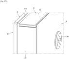
- a front appearance of the refrigerator 1 may be formed in the state in which the door 20 is closed and may form the out appearance of the refrigerator 1 viewed from the front in the state in which the refrigerator 1 is installed.
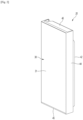
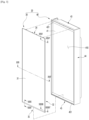
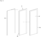
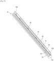
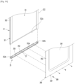
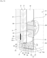
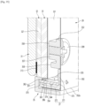
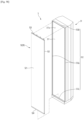
- FIG. 2 is a perspective view of a refrigerator door according to an embodiment present disclosure.
- FIG. 3 is an exploded perspective view of the refrigerator door.
- the door body 40 may include a body plate 41 forming a front surface and a door liner 42 forming a rear surface.
- the body plate 41 may be formed of a metal material and may be formed in a plate shape having a size corresponding to the panel assembly 30.
- the door liner 42 may be formed of a plastic material and may form a bottom sshape of the door 20.
- the door body 40 may include a side deco 44 forming right and left side surfaces of the door body 21.
- the side deco 44 may connect right and left side ends of the body plate 41 and right and left side ends of the door liner 42.
- a rear surface of the panel assembly 30 may be fixed in contact with the body plate 41.
- a lower end of the panel assembly 30 may be caught and restrained with a lower end of the lower cap deco 45, and an upper end of the panel assembly 30 may be coupled to an upper end of a front surface of the upper cap deco 43 to firmly couple the panel assembly 30 to the door body 40.
- the panel assembly 30 may be detachably mounted from the door body 40 for services and maintenance.
- a front surface of the panel assembly 30 may be exposed forward in the state in which the panel assembly 30 is mounted on the door body 40, and the panel assembly 30 may substantially form the front appearance of the door 20.
- the panel assembly 30 may be configured to emit light from an entire front thereof and may be configured to glow with various colors.
- a lighting device 36 may be provided inside the panel assembly 30.
- a wire 381 may be connected to the lighting device 36 in order to supply and control power.
- the wire 381 may be exposed outside the rear surface of the panel assembly 30, and a connector 382 may be provided on an end of the wire 381.
- a structure connected to the connector 382 of the wire 381 to supply power to the lighting device 36 may be provided on a front surface of the door body 40.
- the wire 381 and the connector 382 may be configured to supply power to the lighting device 36 and thus may be referred to as a power supply.
- the power supply may also have a structure that is exposed in the form of a terminal and comes into smooth contact with a mating terminal disposed on the door body 40 to supply power to the lighting device 36.
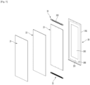
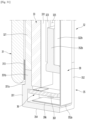
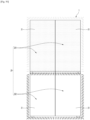
- FIG. 4 is a perspective view of a panel assembly viewed from the rear according to an embodiment of the present disclosure.
- FIG. 5 is an exploded perspective view of the panel assembly viewed from the front.
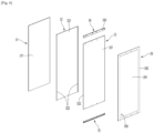
- FIG. 6 is an exploded perspective view of the panel assembly viewed from the rear.
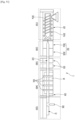
- the panel assembly 30 may include a panel 31 forming a front appearance, the lighting device 36 for emitting light to cause the panel 31 to glow, a light guide plate 33 for guiding light emitted from the lighting device 36, and a member 32 on which the panel 31 is mounted.
- the panel assembly 30 may include an upper bracket 34 forming an upper surface of the panel assembly 30 and a lower bracket 35 forming a lower surface of the panel assembly 30.
- the lighting device 36 may be mounted on the lower bracket 35.
- the panel assembly 30 may further include a back cover 39 forming a rear surface.
- the panel 31 may be formed in a rectangular plate shape and may be formed of a material that transmits light therethrough.
- the panel 31 may be formed of a glass material such as blue glass, white glass, and vapor deposition glass or may be formed of other materials for transmitting light therethrough, such as ABS, PMMA, or PC.
- the panel 31 may be formed with a set thickness for preventing the panel 31 from breaking easily due to the features of the panel 31 that forms an outer appearance.
- the panel 31 may be formed with a larger thickness than the light guide plate 33.
- the panel 31 may be formed with a thickness of about 3 mm to 5 mm.
- the panel 31 may be referred to as a transparent plate or an out plate.
- the panel 31 may be formed to be transparent to allow light reflected by the light guide plate 33 to be transmitted.
- the transparency may be defined as a degree to which the light reflected by the light guide plate 33 is transmitted and irradiated to the outside to identify that the panel 31 glows with specific color.
- the "transparency” and “transmittance” may be defined as the state in which it is possible to cause light to pass through the panel 31 and to represent set color through the panel 31.
- the panel 31 may be formed to have color and may be formed to represent different colors depending on an operation or on and off states of the lighting device 36.
- a specific design or pattern may be printed on the panel 31 to have specific color.
- a film with a specific design or pattern printed thereon may be added to the panel 31, surface treatment such as imprinting, etching, and glass printing may be performed on the panel 21, or a coating or deposition layer having specific color and texture may be formed to form an outer appearance of the panel 31.
- the front plate 31 may be configured to transmit light emitted from the lighting device 36 but components behind the front plate 31 may not be seen therethrough. That is, in the state in which the lighting device 36 is turned off, components inside the panel assembly 30 may be prevented from being seen to the outside through the panel 31 due to the color of the panel 31.
- a color layer 311 having color may be formed on the panel 31.
- the color layer 311 may be formed to have at least color having brightness equal to or greater than 0 other than black. That is, in a state in which the refrigerator 1 is installed, the front surface of the refrigerator 1 may be displayed in a color other than black, and the front color of the refrigerator may be changed according to an operation of the lighting device 36.
- the panel 31 may be formed to correspond to a size of a portion of a front surface of the panel assembly 30, which is exposed to the outside.
- an upper end and right and left side ends of the panel 31 except for a lower end may be formed to have the same size as those of the panel assembly 30.
- the lower end of the panel 31 may be positioned somewhat higher than the lower end of the panel assembly 30, that is, the lower end of the lower bracket 35, but the exposed portion of the lower bracket 35 may be shielded by the lower cap deco 45 in the state in which the panel assembly 30 is mounted.
- the entire front surface of the panel 31 which is exposed to the outside in the state in which the panel assembly 30 is mounted may be formed by the panel 31.
- the panel 31 may be formed to be larger than the light guide plate 33.
- a rear surface of the panel 31 may be coupled to a front surface of the member 32.
- a separate component is not present at the perimeter of the panel 31, and the panel 31 may form the front appearance of the panel assembly 30.
- the light guide plate 33 may be positioned at a rear spaced apart from the panel 31 and may be configured to guide light emitted from the lighting device 36 disposed at the upper end of the light guide plate 33 forward.
- the light guide plate 33 may be formed of transparent acrylic, plastic, or a transparent polymer material.
- the light guide plate 33 may have a light diffuser added thereto for diffusing light incident on the light guide plate 33 or a pattern for diffusing light may be further formed on the light guide plate 33.
- light may be transferred to the panel 31 by the light guide plate 33, and in this case, a pattern of the light guide plate 33 may be set to cause the entire front surface of the panel 31 to glow with uniform brightness.
- the light guide plate 33 may be entirely formed in a rectangular plate shape and may be formed with a somewhat smaller size than that of the panel 31.
- the light guide plate 33 may be supported by the back cover 39 from the rear and may be fixed to be maintained at a predetermined interval from the panel 31 by the member 32.
- the light guide plate 33 may be formed with a set thickness to reflect light emitted from the lighting device 36 toward the panel 31.
- the light guide plate 33 may have a thickness for providing the amount of light to cause the entire panel 31 to sufficiently glow.
- the panel 31 is formed with a thickness of about 3.2 mm
- the light guide plate 33 may be formed with a thickness of about 2 mm.
- the member 32 may be disposed between the panel 31 and the light guide plate 33.
- the member 32 may be used to fixedly mount the light guide plate 33 and the panel 31, and in particular, may maintain the light guide plate 33 at a predetermined interval from the panel 31.
- the member 32 may include the front part 321 shaped like a plate, and the side part 322 that protrudes rearward from the right and left side ends of the front part 321.
- the front part 321 may be disposed between the panel 31 and the light guide plate 33, the front surface may support the panel 31, and the rear surface may support the light guide plate 33.
- the sealant 313 may be compressed. That is, the sealant 313 may be uniformly distributed on a surface of the panel 31 in a state in which the panel 31 and the member 32 are coupled, and thus light emitted from the lighting device 36 may be uniformly transmitted.
- a liquefied sealant may be compressed and spread while the front plate and the support member are fixed, and a boundary between the sealant 313 and the panel 31 may become unclear. Accordingly, advantageously, a boundary line between the sealant 313 and the panel 31 may not be visible from the front of the panel 31.
- the sealant 313 may be cured in a state of being coupled to the member 32.
- the sealant 313 may be formed with a width W of about 4 to 9 mm, in detail, 5 to 7 mm.
- the width may refer to a distance W between outer and inner edges of the sealant 313.
- the width of the sealant 313 is less than 4 mm, coupling force between the panel 31 and the member 32 by the sealant 313 is lowered, and thus it may be possible to prevent the panel 31 from being separated from the member 32 or to prevent the panel 31 from flowing and being provided in a correct position.
- the width of the sealant 313 is greater than 9 mm, the amount of light transmitted through the panel 31 may be reduced by the sealant 313, and a portion coated with the sealant 313 may be darker than a portion that is not coated with the sealant 313.
- the sealant 313 may be coated on an area of about 1 to 5%, in detail, 2 to 4% based on 100% of the total area of a rear surface of the panel 31 or a front surface of the member 32. Within this range, it may be possible to prevent the panel 31 and the member 32 from being separated and to prevent light transmission from being blocked by the sealant 313.
- a difference in light transmission between a portion of the panel 31, which is coated with the sealant 313, and a portion of the panel 31, which is not coated with the sealant 313, may be less than 10%, in detail, less than 5%, in more detail, less than 3%.
- a difference in brightness between a portion of the panel 31, which is coated with the sealant 313, and a portion of the panel 31, which is coated with the sealant 313, may be less than 10%, in detail, less than 5%, in more detail, less than 3%.
- An inner end of the sealant 313 coated on both side surfaces of the panel 31 or the member 32 may be positioned between a second part 323 and a third part 322b of the member 32.
- the inner end of the sealant 313 may extend more inward than the inner end of the second part 323.
- the inner end of the sealant 313 may be positioned outside the inner end of the third part 322b of the member 32.
- the term 'inner' may refer to an end corresponding to a direction in which the sealant 313 extends from the member 32 based on a view of the member 32 from the front.
- a horizontal length of the sealant 313 coated on both side surfaces of the panel 31 or the member 32 may be approximately shorter than a length by which the third part 322b of the member 32 extends more inward than the first part 322a.
- a difference in light transmittance between a portion coated with the sealant 313 and a portion that is not coated with the sealant 313 may be 10% or less.
- the sealant 313 may be coated along upper and lower ends of the member 32.
- the sealant 313 coated on an upper end of the member 32 may be positioned above an upper end of a support rib 347.
- An upper end of the sealant 313 coated along the upper end of the member 32 may be positioned below the upper end of the upper bracket 34 and may be positioned below an upper end of the panel 31.
- the sealant 313 coated on a lower end of the member 32 may be coated up to, for example, a position at which the lower end of the sealant 313 corresponds to the lower end of the lower bracket 35.
- the sealant 313 coated on the lower end of the panel 31 may be positioned above, for example, an upper end of the light source.
- the panel 31 or the member 32 may not require a concave groove for guiding a position to which the sealant 313 is applied or for preventing the sealant 313 from being moved after being attached to the panel 31 or the member 32.
- an operation of assembling the panel 31 and the member 32 may be advantageously simplified.
- the rear surface of the front part 321 may be maintained in the state of being in contact with the front surface of the light guide plate.
- the light guide plate 33 may always be maintained at a predetermined interval and may direct light of an entire part of the light guide plate 33 toward the panel 31 without being interfered.
- the front part 321 may be molded to maintain a set flatness, and thus when the light guide plate 33 is mounted, the front part 321 may be in contact with the entire front surface of the light guide plate 33. Thus, it may be important to mold the front part 321 and the light guide plate 33 to prevent an irregular interval or gap from being formed therebetween.
- the panel 31 may be adhered to the front part 321 by the adhesive member 313.
- the panel 31 may be indirectly coupled to the front part 321 by the front part 321 and the adhesive member 313, and this may be considered as the state of being spaced apart from the front part 321.
- the light guide plate 33 may be disposed to be in contact with the rear surface of the front part 321.
- the front surface of the light guide plate 33 and the rear surface of the front part 321 may be in contact with each other, but may be in simple contact with each other rather than being completely adhered or attached to each other.
- the side part 322 may be formed along the right and left side ends of the light guide plate 33.
- the side part 322 may be stepped with upper and lower ends of the light guide plate 33 and may be formed to match with side ends of the upper bracket 34 and the lower bracket 35.
- the side part 322 may include a first part 322a extending rearward from the right and left side ends of the front part 321 and a second part 323 protruding to face each other in an internal surface of the first part 322a at both ends.
- the side part 322 may further include a third part 322b at an end of the first part 322a. That is, the side part 322 may include the first part 322a and the second part 323, and as necessary, may further include the third part 322b.
- the first part 322a may extend perpendicularly to the front part 321 from the right and left side ends of the front part 321 and may form a side surface of the panel assembly 30.
- An internal space of the panel assembly 30 may be defined by the first part 322a and may form a space for mounting at least the light guide plate 33 therein.
- the side part 322 may further form a space for mounting the upper bracket 34 and the lower bracket 35 therein.
- the third part 322b may be bent inward from an extending end of the first part 322a. That is, one pair of the third parts 322b that are formed on one pair of the first parts 322a, respectively, may extend to face each other.
- a second part 323 may be further formed on an internal surface of the first part 322a.
- the second part 323 may be formed between the front part 321 and the third part 322b and may extend perpendicularly to the first part 322a.
- the second part 323 may extend from an upper end of the first part 322a to a lower end thereof.
- the right and left width of the second part 323 may be shorter than that of the third part 322b.
- the second part 323 may be positioned between the right and left side ends of the light guide plate 33 and the right and left side ends of the lower bracket 35. That is, the second part 323 may be provided at the rear based on the light guide plate 33 and may be positioned at the front based on the right and left side ends of the upper bracket 34 and the lower bracket 35.
- the second part 323 may be positioned between the front part 321 and the third part 322b and may be formed in parallel to the front part 321 and the third part 322b.
- the second part 323 may partition a space between the front part 321 and the third part 322b to form a first space 324 into which the light guide plate 33 is inserted, and a second space 325 into which the upper bracket 34 and the lower bracket 35 are inserted.
- the first space 324 may be formed between the front part 321 and the second part 323.
- a front-to-rear distance of the first space 324 may be formed with a size corresponding to the thickness of the light guide plate 33.
- the light guide plate 33 may be slidably inserted along the side part 322, and thus may not be in close contact with the rear surface of the front part 321, and accordingly, a fine gap may be formed and the light guide plate 33 may be slidably inserted thereinto. That is, the front part 321 and the light guide plate 33 may be in contact with each other without being limited thereto, and at least a portion of the light guide plate 33 may be spaced apart from the front part 321.
- the lower end of the light guide plate 33 may be positioned to face the lighting device 36.
- the light guide plate 33 may be disposed on the same extension line as the light source 362 of the lighting device 36, and in the state in which the light guide plate 33 is fixedly inserted into the first space 324, movement in forward and backward directions of the light guide plate 33 may be restrained.
- the light guide plate 33 may be in contact with the front part 321, may be maintained at a predetermined interval from the panel 31, and may not deviate from a position at which the light guide plate 33 is originally installed.
- the state in which the light guide plate 33 is disposed on the same extension line as the light source 362 included in the lighting device 36 may be maintained, and thus it may be possible to ensure that light emitted from the light source 362 is directed toward an end of the light guide plate 33.
- the second space 325 may be formed between the second part 323 and the third part 322b.
- the front-to-rear distance of the second space 325 may correspond to the thickness of an upper bracket front part 341 and a lower bracket front part 351.
- the upper bracket 34 and the lower bracket 35 may be inserted into the second space 325 from above and below and may be fixedly mounted on the upper and lower ends of the member 32.
- an upper end protrusion 321b and a lower end protrusion 321a that further protrude compared with the upper and lower ends of the side part 322 may be formed on the upper and lower ends of the front part 321.
- the upper bracket 34 and the lower bracket 35 that are mounted on the upper and lower ends of the member 32 may be assembled with directivity to prevent misassembly, and the upper bracket 34 and the lower bracket 35 may be more firmly and fixedly mounted.
- the upper bracket 34 when the upper bracket 34 is mounted, right and left sides of the upper bracket 34 may be supported by the upper end of the side part 322, and a front end of the upper bracket 34 may be supported by the upper end protrusion 321b.
- the upper bracket 34 may be simultaneously supported by the side part 322 and the front part 321 and may also have a temporary fixed structure even before the screws 399 is coupled.
- the upper bracket 34 In the state in which the upper bracket 34 is completely mounted, the upper bracket 34 may be coupled to the front part 321 and the side part 322 to be prevented from being distorted or deformed.
- the right and left side ends of the lower bracket 35 may be supported by the lower end of the side part 322, and the front surface of the lower bracket 35 may be supported by the lower end protrusion 321a.
- the lower bracket 35 is simultaneously supported by the side part 322 and the front part 321 and may have a temporary fixed structure even before the screws 399 is coupled.
- the lower bracket 35 may be coupled to the front part 321 and the side part 322 to be prevented from being distorted and deformed.
- the upper bracket 34 and the lower bracket 35 may be inserted into the second space 325, and simultaneously, may be accommodated on a stepped portion of the upper and lower ends of the side part 322 and the front part 321 to be firmly coupled to the member 32.
- the upper and lower ends of the panel assembly 30 may be formed.
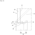
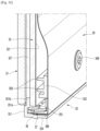
- FIG. 15 is a diagram showing a coupling structure of the member, the panel, and the light guide plate.
- FIG. 16 is an enlarged view of a part "E" of FIG. 15 .
- FIG. 17 is an exploded perspective view taken along XVII-XVII' of FIG. 3 .
- the member 32 may be used to mount the panel 31 on the front part 321 and to mount the light guide plate 33 on the side part 322. That is, it may be possible to mount the panel 31 and the light guide plate 33 by a single component of the member 32.
- the panel 31 and the light guide plate 33 may be spaced apart in forward and rearward directions across the member 32 therebetween, and in this case, an interval between the panel 31 and the light guide plate may be maintained by as much as the thickness of the front part 321.
- the member 32 may be formed of a light-transmissive material to transmit light reflected from the light guide plate 33 at the rear to the panel 31 in the front.
- the member 32 may be formed of a transparent or translucent material for transmitting light therethrough and may have color for transmitting light.
- the front part 321 may have a size corresponding to the panel 31, and at least an upper end and a right and left side ends of the front part 321 may be formed in a plate shape corresponding to the right and left side ends of the panel 31.
- the adhesive member 313 for adhering the panel 31 to the front part 321 may be provided on a perimeter of a bottom surface of the panel 31.
- the adhesive member 313 may be formed along an entire perimeter of the panel 31, and the panel 31 may be firmly fixed to the front surface of the front part 321.
- the front surface of the panel assembly 30 may be formed by the panel 31, and any structure for fixing the panel 31 and the light guide plate 33 may not be exposed. That is, the front surface of the panel assembly 30 may be formed by the panel 31, and the entire portion of the panel 31 may glow without a bezel or fixed structure to form an outer appearance of the entire front surface of the panel assembly 30 or the door 20.
- the adhesive member 313 may be formed of a transparent or translucent material to transmit light reflected from the light guide plate 33 therethrough.
- the adhesive member 313 may be formed by coating a transparent or translucent sealant and may be formed by an adhesive such as a transparent or translucent double-side tape.
- the side part 322 may protrude rearward from the right and left side ends of the front part 321, and one pair of the side parts 322 may be opened to face each other.
- the side part 322 may be opened in a vertical direction, and the light guide plate 33 may be inserted into the side part 322 through an insertion space while being slidably moved in a vertical direction.
- the insertion space of the light guide plate 33 may be formed between the rear surface of the front part 321 and the third part.
- the light guide plate 33 may be inserted into the side part 322 in the state being in contact with the rear surface of the front part 321, and in the state in which the light guide plate 33 is in completely contact with the rear surface, the front surface of the light guide plate 33 may be in contact with the rear surface of the front part 321.
- both ends of the reflective sheet 331 may be accommodated inside the first space 324, and the reflective sheet 331 at right and left side surfaces of the light guide plate 33 may be accommodated therein.
- the reflective sheet 331 may prevent light from leaking the outside through the side part 322.
- the pattern part 333 of the light guide plate 33 and the edge reflector 331a of the reflective sheet 331 may be arranged at a position corresponding to a region in which the adhesive member 313 is disposed. That is, at least the adhesive member 313 may be positioned in an internal region of the pattern part 333 and/or the edge reflector 331a.
- the panel 31 may glow with uniform brightness and color without shadow due to the adhesive member 313.
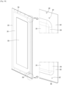
- FIG. 16 is a perspective view of a back cover as one component of the panel assembly.
- the back cover 39 may be formed in a rectangular plate shape to form a rear surface of the panel assembly 30.
- the back cover 39 may be formed of a metal material such as steel or aluminum and may form the overall shape by a foaming process.
- the cover protrusion 391 may form most of the area of the back cover 39 except for the cover perimeter part 392 and may protrude forward to support the light guide plate 33 from the rear.
- a protruding front surface of the cover protrusion 391 may be formed in a flat shape with a uniform height to support most of the area of the light guide plate 33.
- the cover protrusion 391 may protrude when the back cover 39 is molded and may be formed to be recessed forward viewed from the rear.
- a space may be formed between a rear surface of the panel assembly 30 and a front surface of the door body 40. That is, when heat generated during an operation of the lighting device 36 conducted along the rear surface of the panel assembly 30, i.e., the back cover 39 is transferred through the back cover 39, a space for heat dissipation through the rear surface of the panel assembly 30 may be formed.
- a buffer member 393 may be further provided on the cover protrusion 391.
- the buffer member 393 may be formed of an elastically deformable material and may be formed in the form of a sheet to be attached to the cover protrusion 391.
- the buffer member 393 may be formed of an expandable material or a foaming material and may be in close contact with the light guide plate 33 to support the light guide plate 33.
- the buffer member 393 may prevent the light guide plate 33 from shaking and alleviate impact transferred to the light guide plate 33 to protect the light guide plate 33. Even when the light guide plate 33 is deformed while being compressed or expanded by heat, a space in which the light guide plate 33 is deformable may be provided.
- the support ribs 347 may protrude with the same height as a protruding height of the upper bracket boss 346. Thus, when the panel assembly 30 is assembled, the support ribs 347 may support the light guide plate 33 from the rear with the upper bracket boss 346.
- the upper bracket upper part 342 may be formed on the upper end of the upper bracket front part 341.
- the upper bracket upper part 342 may extend in a direction perpendicular to the upper bracket front part 341.
- the upper bracket boss 346 may protrude at the same height as the upper support 347, and thus the upper bracket boss 346 may support the upper end of the light guide plate 33 from the rear with the upper support 347. As such, the upper part of the light guide plate 33 may be supported only by the structure in which the upper bracket 34 is inserted into the member 32.
- the screw 399 passing through the upper end of the back cover 39 may be coupled to the upper bracket boss 346 to firmly fix the upper bracket 34.
- the upper bracket 34 may be inserted into the member 32 to be primarily fixed thereto, and may be connected to the lower bracket 35 by the back cover 39 to be secondarily fixed thereto by the screw 399.
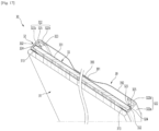
- FIG. 27 is a perspective view in which a lower bracket, a lighting device, and a right supporter as components of panel assembly are coupled.
- FIG. 28 is an exploded perspective view showing a coupling structure of the lower bracket, the lighting device, and the right supporter viewed from the rear.
- FIG. 29 is an exploded perspective view showing a coupling structure of the lower bracket, the lighting device, and the right supporter from the front.
- FIG. 30 is a partial exploded perspective view showing a coupling structure of the member, a lower bracket, and a back cover.
- FIG. 31 is an exploded perspective view taken along XXXI-XXXI' of FIG. 3 .
- FIG. 32 is an exploded perspective view taken along XXXII-XXXII' of FIG. 4 .
- FIG. 33 is an exploded perspective view taken along XXIII-XXXIII' of FIG. 3 .
- FIG. 34 is a perspective view taken along XXXIV-XXXIV'
- the lower bracket front part 351 form a shape of the front surface of the lower bracket 35 and may support the panel 31. A portion of the lower bracket front part 351 may protrude below the panel 31 and may be inserted into the lower end of the door body 40, that is, the lower cap deco 45 to fix the lower bracket 35.
- the lower bracket front part 351 may include a bracket stepped part.
- the bracket stepped part may include a first stepped part 351a for supporting a lower end of the panel 31 and a second stepped part 351b for supporting the panel 31 from the rear.
- the first stepped part 351a may be stepped rearward on the front surface of the lower bracket front part 351, and the second stepped part 351b may extend upward from the rear end of the first stepped part 351a.
- the adhesive member 313 may be coated on the second stepped part 351b, and thus the panel 31 may be firmly fixed.
- the upper end of the second stepped part 351b may be coupled to the lower end of the member 32, and thus the front surface of the second stepped part 351b and the front part 321 of the member 32 may be positioned on the same plane.
- the second stepped part 351b may support the panel 31, and simultaneously, may prevent the lighting device 36 or a lighting spot (which may also be referred to as light formation or a hot spot) generated by the lighting device 36 from being exposed.
- the lower bracket side part 353 may form a side surface of the lower bracket 35 and may protrude above the lower bracket front part 351.
- the lower bracket side part 353 may protrude above the second stepped part 351b, and thus a stepped portion of a lower end of the side surface of the member 32 may be coupled to engage each other with the lower bracket front part 351 and the lower bracket side part 353.
- the lower bracket rear part 352 may be formed on a rear end of the lower bracket side part 353.
- the lower bracket rear part 352 may form a rear surface of the lower bracket 35 and may fixedly mount the lower bracket 35 on the member 32.
- the lower bracket rear part 352 may be formed in parallel to the panel 31 and the light guide plate 33 and may extend in a vertical direction. A rear surface part of the lower bracket 35 may protrude above the lower bracket front part 351 and the lower bracket side part 353.
- a lower side part 352b stepped forward may be formed on right and left side ends of the lower bracket rear part 352.
- the lower side part 352b may be stepped with the lower bracket rear part 352 and may be positioned in the front of the lower bracket front part 351.
- the lower side part 352b may be formed with a thickness corresponding to the width of the second space 325 and may be slidably inserted upward from a lower part of the second space 325.
- the lower bracket 35 may be mounted at a lower end of the member 32.
- the lower bracket 35 may be inserted upward from a lower part through an open lower surface of the bracket insertion space 325.
- the lower bracket rear part 352 may be disposed inside the member 32 and may be disposed between the side parts 322 at both left and right sides.
- both left and right ends of the lower bracket rear part 352, that is, the lower side parts 352b may be inserted into the bracket insertion space 325 to fixedly mount the lower bracket 35 on the upper end of the member 32.
- the lower bracket side part 353 may be accommodated on the lower end of the side part 322.
- the lower bracket 35 may be stepped with a shape corresponding to a lower stepped surface of the member 32, and the lower bracket 35 and the member 32 may be coupled to each other.
- the lower side part 352b is inserted into the bracket insertion space 325 positioned behind the light guide plate 33, no shading may be generated on the panel 31 when light is reflected by the light guide plate 33. That is, the lower bracket 35 may not be exposed out of the panel 31 in the state of being fixedly mounted on the member 32 and may not block light reflected by the light guide plate 33.
- the lower support 358 protruding on the front surface of the lower bracket rear part 352 may support a lower end of the rear surface of the light guide plate 33 or a lower part close to the lower end.
- the right supporter 37 may be formed of a metal material and may be molded by extrusion to have the same cross-sectional structure in a longitudinal direction, and may be formed with a size to enter and exit through the bracket opening 352a.
- the lower bracket 35 may be mounted on the lower end of the member 32.
- the lower bracket 35 may extend downward based on the panel 31.
- the lighting device 36 may be disposed inside the lower bracket 35, and the upper end of the lighting device 36 may be disposed below the panel 31.
- the lighting device 36 may be disposed below the panel 31, thereby preventing a light source from being exposed or preventing a lighting spot from being formed on the panel 31.
- an outer appearance of the panel assembly 30 may be formed by the panel 31, and a side appearance of the panel assembly 30 may be formed by the member 32.
- the upper bracket 34 and the lower bracket 35 may be accommodated on the upper and lower ends of the member 32 to be shielded by the panel 31.
- an outer appearance of the panel assembly 30 may be entirely determined by the panel 31, and in particular, color of the panel assembly 30 may be determined according to a color change of the panel 31.
- the light guide plate 33 may be disposed within the member 32, and the lighting device 36 may be accommodated inside the lower bracket 35, and thus the panel assembly 30 may have a slim overall structure.
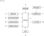
- FIG. 40 is a block diagram showing a flow of a control signal of the refrigerator.
- FIG. 41 is a cross-sectional view showing a lighting state of the panel assembly.
- FIG. 42 is an enlarged view of a part "F” of FIG. 41 .
- FIG. 43 is an enlarged view of a part "G” of FIG. 41 .
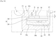
- FIG. 44 is an enlarged view of a part "H” of FIG. 41 .
- a front surface of the door 20 may glow via an operation of the lighting device 36.
- the front surface of the door 20 may be turned on or off and may glow with any one of a plurality of colors under control of the controller 13.
- the user may set the overall operation state of the lighting device 36, such as an operation time and an operation condition of the lighting device 36 and emission color of the light source 362 through manipulation of the manipulator 14.
- the manipulator 14 may be configured as a display for information display and manipulation.
- the lighting device 36 may also be manipulated and set through a remote device 2 spaced apart from the refrigerator 1.
- the refrigerator 1 may communicate with the remote device 2 through a communicator 17 connected to a controller 13, and the user may manipulate an operation of the lighting device 36 through the remote device 2.
- the communicator 17 may communicate with the remote device 2 using various methods.
- the communicator 17 may have a communicable structure using at least one method such as wired, wireless, or short distance communication (Bluetooth, Wi-Fi, Zigbee, and NFC).
- the remote device 2 may be various devices that are capable of communicating, such as a dedicated terminal, a mobile phone, a tablet, a portable PC, a desktop PC, a remote control, or a Bluetooth speaker.
- the user may manipulate and set the overall operation state of the lighting device 36, such as an operation time and an operation condition of the lighting device 36 and emission color through manipulation of the remote device 2.
- the lighting device 36 may be simply manipulated and set through an application or a dedicated program installed in a portable phone of the user.
- the lighting device 36 may also be operated by a sensor.
- the sensor may be, for example, a user detection sensor 151 for detecting proximity of the user.
- the user detection sensor 151 may use various devices for detecting user approaching near the refrigerator, such as an infrared sensor, an ultrasonic sensor, or a laser sensor.
- the sensors 15 may be disposed at various positions for detecting proximity of the user, such as one side of the cabinet or one side of the door 20, and may be disposed at various positions for detecting proximity of the user. A plurality of sensors may be disposed at different positions.
- the user detection sensor 151 may detect this and may transfer a signal to the controller 13 to turn on the lighting device 36.
- the user detection sensor 151 may detect this and may transfer a signal to the controller 13 to turn off the lighting device 35.
- the lighting device 36 may be turned off or the brightness may be gradually dimmed to prevent glare of the user.
- the lighting device 35 may be turned on again or may return to an original brightness.
- the lighting device 36 may be operated according to a detected illumination of the illumination sensor 152. For example, when the detected illumination of the illumination sensor 152 is equal to or less than a set illumination and the lighting device 36 is dimmed, the controller 13 may turn on the lighting device 36, and when the detected illumination of the illumination sensor 152 is equal to or greater than the set illumination and the lighting device 36 becomes brighter, the controller 13 may turn off the lighting device 36.
- the sensor may include both the illumination sensor 152 and the user detection sensor 151, and the illumination sensor 152 and the user detection sensor 151 may be operated in a complex way to cause the controller 13 to turn off the lighting device 36.
- the lighting device 36 may be maintained in an off state irrespective of whether the user detection sensor 151 detects this.
- the lighting device 36 may be turned on.
- the sensor may be an inside temperature sensor 153.
- the controller 13 may be connected to the inside temperature sensor 153.
- the inside temperature sensor 153 may detect a temperature inside the refrigerator and may transfer the detected temperature to the controller 13, and the controller 13 may cause the light source 362 to glow with set color according to the temperature inside the refrigerator and may intuitively display the temperature and state inside the refrigerator through front color of the door 20.
- the lighting device 36 may include the state in which brightness is adjusted in addition to an on state and an off state. That is, according to an operation state of the refrigerator 1, the controller 13 may adjust the operation state of the refrigerator 1 by changing brightness of the lighting device 36.
- the controller 13 may be connected to a microphone 18.
- the light source 362 may glow with set color according to a voice signal received from the microphone 18, and an input state of the voice signal or a setting state of a function may also be displayed through the front color of the door 20.
- the controller 13 may adjust a set temperature inside the refrigerator, and may operate the lighting device 36 to change color of the front surface of the door 20 to color corresponding to the corresponding temperature.
- the lighting device 36 may also be controlled to change the front color of the door 20 in response to play of music, and the front surface of the refrigerator the door 20 may be continuously changed in color with an equalizer while interacting with the played music.
- the lighting device 36 may be turned off at a time set by a timer 16. That is, the lighting device 36 may be turned on according to a time when the user is mainly active and may be maintained off outside the set time range. In addition, the lighting device 36 may be turned off during the day and on during night irrespective of actual illumination.
- the brightness and color of the front surface of the door 20 may be adjusted only according to user settings.
- the operation state of the lighting device operated by the controller is now described.
- the lighting device 36 when the lighting device 36 is turned on according to an instruction of the controller 13, light emitted from the light source 362 may be directed toward the lower end of the light guide plate 33.
- light emitted from the light source 362 may glow with color selected by the controller 13. That is, the light source 362 may be an RGB LED and may emit light with color determined by the controller 13 to cause a surface of the panel 31 to glow with specific color.
- Light incident through the lower end of the light guide plate 33 may be diffused and reflected along the light guide plate 33 and may be moved along the light guide plate 33.
- light guided by the light guide plate 33 may be reflected forward by the reflective sheet 331 and may be transmitted to the outside through the panel 31.
- Light may also be reflected by a perimeter surface the light guide plate 33 to maximize the reflection efficiency of the inside of the light guide plate 33 due to the reflective member 332 disposed on the perimeter of the light guide plate 33.
- light guided through the light guide plate 33 may be entirely emitted forward to cause the panel 31 to entirely glow, and the front surface of the door 20 may glow with set brightness or color.
- the lighting device 36 may be disposed on the lower end of the panel assembly 30, and the light source 362 may emit light upward.
- the lighting device 36 may be fixed to be prevented from being moved inside the lower bracket 35. Thus, even if the door 20 is repeatedly opened and closed, the lighting device 36 may be maintained at an exact position, and the panel 31 may be ensured to glow with set brightness by directing light emitted from the light source 362 toward the lower end of the light guide plate 33.
- an outer appearance of a refrigerator 1' may be formed by the cabinet 10 in which a storage space is formed, and the door 20 for opening and closing an open front surface of the cabinet 10.
- the first space may be formed on the side part, and thus the light guide plate may be slidably inserted and mounted without adding a separate component for coupling the light guide plate.
- the member since the member may be formed of a transparent material, light reflected by the light guide plate may not be hidden, and accordingly, light may be emitted through the entire panel to represent color desired by a user.
Landscapes
- Engineering & Computer Science (AREA)
- Physics & Mathematics (AREA)
- General Engineering & Computer Science (AREA)
- Chemical & Material Sciences (AREA)
- Combustion & Propulsion (AREA)
- Mechanical Engineering (AREA)
- Thermal Sciences (AREA)
- General Physics & Mathematics (AREA)
- Optics & Photonics (AREA)
- Refrigerator Housings (AREA)
- Devices That Are Associated With Refrigeration Equipment (AREA)
Applications Claiming Priority (4)
| Application Number | Priority Date | Filing Date | Title |
|---|---|---|---|
| KR1020210091835A KR20230011154A (ko) | 2021-07-13 | 2021-07-13 | 냉장고 및 가전기기 |
| KR1020210091832A KR20230011153A (ko) | 2021-07-13 | 2021-07-13 | 냉장고 및 가전기기 |
| KR1020210091825A KR20230011147A (ko) | 2021-07-13 | 2021-07-13 | 냉장고 및 가전기기 |
| EP22184627.2A EP4119873B1 (de) | 2021-07-13 | 2022-07-13 | Haushaltsgerät |
Related Parent Applications (1)
| Application Number | Title | Priority Date | Filing Date |
|---|---|---|---|
| EP22184627.2A Division EP4119873B1 (de) | 2021-07-13 | 2022-07-13 | Haushaltsgerät |
Publications (2)
| Publication Number | Publication Date |
|---|---|
| EP4579161A2 true EP4579161A2 (de) | 2025-07-02 |
| EP4579161A3 EP4579161A3 (de) | 2025-08-27 |
Family
ID=82594574
Family Applications (2)
| Application Number | Title | Priority Date | Filing Date |
|---|---|---|---|
| EP25170110.8A Pending EP4579161A3 (de) | 2021-07-13 | 2022-07-13 | Haushaltsgerät |
| EP22184627.2A Active EP4119873B1 (de) | 2021-07-13 | 2022-07-13 | Haushaltsgerät |
Family Applications After (1)
| Application Number | Title | Priority Date | Filing Date |
|---|---|---|---|
| EP22184627.2A Active EP4119873B1 (de) | 2021-07-13 | 2022-07-13 | Haushaltsgerät |
Country Status (4)
| Country | Link |
|---|---|
| US (2) | US12235036B2 (de) |
| EP (2) | EP4579161A3 (de) |
| CN (1) | CN115615115A (de) |
| AU (2) | AU2022205217B2 (de) |
Families Citing this family (6)
| Publication number | Priority date | Publication date | Assignee | Title |
|---|---|---|---|---|
| KR20230071579A (ko) * | 2021-11-16 | 2023-05-23 | 엘지전자 주식회사 | 가전 기기 |
| KR20230071624A (ko) * | 2021-11-16 | 2023-05-23 | 엘지전자 주식회사 | 가전 기기 |
| KR20230071580A (ko) * | 2021-11-16 | 2023-05-23 | 엘지전자 주식회사 | 가전 기기 |
| KR20230075701A (ko) * | 2021-11-23 | 2023-05-31 | 엘지전자 주식회사 | 가전 기기 |
| KR102900195B1 (ko) * | 2022-06-27 | 2025-12-15 | 엘지전자 주식회사 | 도어 업그레이드 키트 및 이를 포함하는 냉장고 |
| KR20240002821A (ko) * | 2022-06-30 | 2024-01-08 | 엘지전자 주식회사 | 냉장고 |
Citations (3)
| Publication number | Priority date | Publication date | Assignee | Title |
|---|---|---|---|---|
| CN103250018A (zh) | 2010-12-08 | 2013-08-14 | Bsh博世和西门子家用电器有限公司 | 具有被照明的门的冷却设备 |
| US8789900B2 (en) | 2005-05-10 | 2014-07-29 | Bsh Bosch Und Siemens Hausgerate Gmbh | Door for a household appliance |
| KR20180067382A (ko) | 2016-12-12 | 2018-06-20 | 엘지전자 주식회사 | 냉장고 |
Family Cites Families (47)
| Publication number | Priority date | Publication date | Assignee | Title |
|---|---|---|---|---|
| US6059420A (en) * | 1999-02-17 | 2000-05-09 | Rogers; Thomas | See through refrigerator door construction |
| KR101517230B1 (ko) * | 2008-02-21 | 2015-05-04 | 엘지전자 주식회사 | 냉장고 및 냉장고 도어 |
| KR101576672B1 (ko) * | 2008-02-21 | 2015-12-10 | 엘지전자 주식회사 | 냉장고 및 냉장고 도어 |
| KR101291798B1 (ko) * | 2008-06-10 | 2013-07-31 | 엘지디스플레이 주식회사 | 액정표시모듈 및 그 조립방법 |
| KR101602223B1 (ko) * | 2009-05-22 | 2016-03-10 | 엘지전자 주식회사 | 장식 판넬 및 이를 구비한 냉장고 |
| WO2011093614A2 (en) * | 2010-02-01 | 2011-08-04 | Lg Electronics Inc. | Refrigerator and method for controlling the same |
| KR101713333B1 (ko) * | 2010-09-01 | 2017-03-07 | 엘지전자 주식회사 | 냉장고 도어 |
| KR101843337B1 (ko) * | 2010-10-28 | 2018-03-30 | 삼성전자주식회사 | 디스플레이 모듈 및 디스플레이 시스템 |
| US9052536B2 (en) * | 2011-05-10 | 2015-06-09 | Anthony, Inc. | Display case door with transparent LCD panel |
| FR2978525B1 (fr) * | 2011-07-29 | 2018-05-18 | Saint-Gobain Glass France | Vitrage multiple lumineux de meuble |
| WO2013051473A1 (ja) * | 2011-10-06 | 2013-04-11 | シャープ株式会社 | 照明装置、表示装置、及びテレビ受信装置 |
| ES2533244B1 (es) * | 2013-10-03 | 2016-01-22 | Bsh Electrodomésticos España, S.A. | Aparato doméstico |
| JP6244195B2 (ja) * | 2013-12-19 | 2017-12-06 | 日立アプライアンス株式会社 | 冷蔵庫 |
| JP2015203525A (ja) * | 2014-04-14 | 2015-11-16 | 株式会社東芝 | 冷蔵庫 |
| FR3021093B1 (fr) * | 2014-05-13 | 2020-07-17 | Saint-Gobain Glass France | Ensemble vitre lumineux, porte et meuble refrigere avec cet ensemble et fabrication. |
| KR20160044721A (ko) * | 2014-10-16 | 2016-04-26 | 삼성전자주식회사 | 냉장고 |
| JP2017106637A (ja) * | 2014-12-26 | 2017-06-15 | 三星電子株式会社Samsung Electronics Co.,Ltd. | 冷蔵庫および照明装置 |
| KR101892794B1 (ko) * | 2015-08-25 | 2018-08-28 | 엘지전자 주식회사 | 냉장고 |
| CN107014145A (zh) * | 2016-01-27 | 2017-08-04 | 凌晖科技股份有限公司 | 电器的门板装置 |
| CN105627676A (zh) * | 2016-03-01 | 2016-06-01 | 上海九山电子科技有限公司 | 自带半透明液晶发光结构的冷柜门及其制造方法 |
| KR20170106575A (ko) * | 2016-03-11 | 2017-09-21 | 삼성전자주식회사 | 광원 모듈 및 이를 포함하는 조명 장치 |
| KR102661024B1 (ko) * | 2016-08-23 | 2024-04-26 | 주식회사 위니아 | 냉장고 도어 |
| KR102687627B1 (ko) * | 2016-08-29 | 2024-07-23 | 엘지전자 주식회사 | 냉장고 |
| KR102273092B1 (ko) * | 2016-12-12 | 2021-07-06 | 엘지전자 주식회사 | 냉장고 |
| JP6868401B2 (ja) * | 2017-01-18 | 2021-05-12 | 東芝ライフスタイル株式会社 | 冷蔵庫 |
| KR102733673B1 (ko) * | 2017-01-23 | 2024-11-26 | 엘지전자 주식회사 | 냉장고 및 냉장고용 패널 어셈블리 |
| KR102259753B1 (ko) * | 2017-03-24 | 2021-06-02 | 엘지전자 주식회사 | 냉장고 |
| KR102423822B1 (ko) * | 2017-04-25 | 2022-07-21 | 엘지전자 주식회사 | 냉장고 |
| CN108931100A (zh) * | 2017-05-26 | 2018-12-04 | 东芝生活电器株式会社 | 冰箱 |
| US10810914B2 (en) * | 2017-08-09 | 2020-10-20 | True Manufacturing Co., Inc. | Illuminating display window and merchandiser display unit comprising same |
| KR102499468B1 (ko) * | 2018-02-12 | 2023-02-15 | 엘지전자 주식회사 | 냉장고 |
| WO2019175978A1 (ja) * | 2018-03-13 | 2019-09-19 | 三菱電機株式会社 | 冷蔵庫及びその冷蔵庫の製造方法 |
| EP3575715B1 (de) * | 2018-05-28 | 2025-06-25 | LG Electronics Inc. | Kühlschrank |
| KR102126864B1 (ko) * | 2018-06-01 | 2020-06-25 | 엘지전자 주식회사 | 냉장고 |
| KR102071659B1 (ko) * | 2018-06-01 | 2020-03-11 | 엘지전자 주식회사 | 냉장고 |
| KR102096957B1 (ko) * | 2018-06-01 | 2020-04-03 | 엘지전자 주식회사 | 냉장고 및 이의 제어방법 |
| KR102187339B1 (ko) * | 2018-06-01 | 2020-12-07 | 엘지전자 주식회사 | 냉장고 |
| DE102018005481B4 (de) * | 2018-07-11 | 2023-03-09 | Emz-Hanauer Gmbh & Co. Kgaa | Haushalts-Kühlgerät mit Bodenbaugruppe und daran angebrachter Leuchtleiste |
| KR102149201B1 (ko) * | 2018-07-13 | 2020-08-28 | 엘지전자 주식회사 | 냉장고 및 냉장고의 제어 방법 |
| WO2020096258A1 (ko) * | 2018-11-08 | 2020-05-14 | 엘지전자 주식회사 | 패널 어셈블리, 냉장고 및 가전제품 |
| CN112797711A (zh) * | 2019-11-13 | 2021-05-14 | Lg电子株式会社 | 冰箱 |
| US12442584B2 (en) * | 2019-12-05 | 2025-10-14 | Lg Electronics Inc. | Refrigerator |
| DE102020109934A1 (de) * | 2020-02-19 | 2021-08-19 | Liebherr-Hausgeräte Ochsenhausen GmbH | Kühl- und/oder Gefriergerät mit Außenbeleuchtungskonzept |
| ES2961137T3 (es) * | 2020-02-21 | 2024-03-08 | Liebherr Hausgeraete Ochsenhausen Gmbh | Frigorífico y/o congelador con iluminación especial del espacio interior |
| KR20210130419A (ko) * | 2020-04-22 | 2021-11-01 | 삼성전자주식회사 | 냉장고 |
| KR20220005218A (ko) * | 2020-07-06 | 2022-01-13 | 엘지전자 주식회사 | 냉장고 |
| KR20220146241A (ko) * | 2021-04-23 | 2022-11-01 | 엘지전자 주식회사 | 냉장고 |
-
2022
- 2022-07-13 EP EP25170110.8A patent/EP4579161A3/de active Pending
- 2022-07-13 EP EP22184627.2A patent/EP4119873B1/de active Active
- 2022-07-13 AU AU2022205217A patent/AU2022205217B2/en active Active
- 2022-07-13 US US17/863,821 patent/US12235036B2/en active Active
- 2022-07-13 CN CN202210826267.0A patent/CN115615115A/zh active Pending
-
2024
- 2024-08-29 AU AU2024216423A patent/AU2024216423A1/en active Pending
-
2025
- 2025-01-23 US US19/035,019 patent/US20250164179A1/en active Pending
Patent Citations (3)
| Publication number | Priority date | Publication date | Assignee | Title |
|---|---|---|---|---|
| US8789900B2 (en) | 2005-05-10 | 2014-07-29 | Bsh Bosch Und Siemens Hausgerate Gmbh | Door for a household appliance |
| CN103250018A (zh) | 2010-12-08 | 2013-08-14 | Bsh博世和西门子家用电器有限公司 | 具有被照明的门的冷却设备 |
| KR20180067382A (ko) | 2016-12-12 | 2018-06-20 | 엘지전자 주식회사 | 냉장고 |
Also Published As
| Publication number | Publication date |
|---|---|
| EP4579161A3 (de) | 2025-08-27 |
| AU2024216423A1 (en) | 2024-09-19 |
| US12235036B2 (en) | 2025-02-25 |
| EP4119873A1 (de) | 2023-01-18 |
| US20250164179A1 (en) | 2025-05-22 |
| CN115615115A (zh) | 2023-01-17 |
| AU2022205217B2 (en) | 2024-05-30 |
| EP4119873B1 (de) | 2025-04-16 |
| US20230018403A1 (en) | 2023-01-19 |
| AU2022205217A1 (en) | 2023-02-02 |
Similar Documents
| Publication | Publication Date | Title |
|---|---|---|
| EP4119873B1 (de) | Haushaltsgerät | |
| US20250164180A1 (en) | Refrigerator and home appliance | |
| US20260016220A1 (en) | Refrigerator | |
| EP4119871B1 (de) | Haushaltsgerät mit einer plattenanordnung | |
| US20250189208A1 (en) | Home appliance | |
| KR20230011153A (ko) | 냉장고 및 가전기기 | |
| US12529512B2 (en) | Refrigerator and home appliance | |
| KR20230011150A (ko) | 냉장고 및 가전기기 | |
| EP4549857A2 (de) | Haushaltsgerät | |
| KR20230011147A (ko) | 냉장고 및 가전기기 | |
| US12215850B2 (en) | Home appliance | |
| KR20230011154A (ko) | 냉장고 및 가전기기 | |
| KR20230071625A (ko) | 가전 기기 | |
| KR20230011148A (ko) | 냉장고 및 가전기기 |
Legal Events
| Date | Code | Title | Description |
|---|---|---|---|
| PUAI | Public reference made under article 153(3) epc to a published international application that has entered the european phase |
Free format text: ORIGINAL CODE: 0009012 |
|
| STAA | Information on the status of an ep patent application or granted ep patent |
Free format text: STATUS: THE APPLICATION HAS BEEN PUBLISHED |
|
| AC | Divisional application: reference to earlier application |
Ref document number: 4119873 Country of ref document: EP Kind code of ref document: P |
|
| AK | Designated contracting states |
Kind code of ref document: A2 Designated state(s): AL AT BE BG CH CY CZ DE DK EE ES FI FR GB GR HR HU IE IS IT LI LT LU LV MC MK MT NL NO PL PT RO RS SE SI SK SM TR |
|
| PUAL | Search report despatched |
Free format text: ORIGINAL CODE: 0009013 |
|
| AK | Designated contracting states |
Kind code of ref document: A3 Designated state(s): AL AT BE BG CH CY CZ DE DK EE ES FI FR GB GR HR HU IE IS IT LI LT LU LV MC MK MT NL NO PL PT RO RS SE SI SK SM TR |
|
| RIC1 | Information provided on ipc code assigned before grant |
Ipc: F25D 27/00 20060101AFI20250724BHEP Ipc: F25D 23/02 20060101ALI20250724BHEP |
|
| STAA | Information on the status of an ep patent application or granted ep patent |
Free format text: STATUS: REQUEST FOR EXAMINATION WAS MADE |
|
| 17P | Request for examination filed |
Effective date: 20251107 |