EP4119873B1 - Haushaltsgerät - Google Patents
Haushaltsgerät Download PDFInfo
- Publication number
- EP4119873B1 EP4119873B1 EP22184627.2A EP22184627A EP4119873B1 EP 4119873 B1 EP4119873 B1 EP 4119873B1 EP 22184627 A EP22184627 A EP 22184627A EP 4119873 B1 EP4119873 B1 EP 4119873B1
- Authority
- EP
- European Patent Office
- Prior art keywords
- panel
- guide plate
- light guide
- panel assembly
- door
- Prior art date
- Legal status (The legal status is an assumption and is not a legal conclusion. Google has not performed a legal analysis and makes no representation as to the accuracy of the status listed.)
- Active
Links
Images


Classifications
-
- F—MECHANICAL ENGINEERING; LIGHTING; HEATING; WEAPONS; BLASTING
- F25—REFRIGERATION OR COOLING; COMBINED HEATING AND REFRIGERATION SYSTEMS; HEAT PUMP SYSTEMS; MANUFACTURE OR STORAGE OF ICE; LIQUEFACTION SOLIDIFICATION OF GASES
- F25D—REFRIGERATORS; COLD ROOMS; ICE-BOXES; COOLING OR FREEZING APPARATUS NOT OTHERWISE PROVIDED FOR
- F25D23/00—General constructional features
- F25D23/02—Doors; Covers
- F25D23/028—Details
-
- F—MECHANICAL ENGINEERING; LIGHTING; HEATING; WEAPONS; BLASTING
- F21—LIGHTING
- F21V—FUNCTIONAL FEATURES OR DETAILS OF LIGHTING DEVICES OR SYSTEMS THEREOF; STRUCTURAL COMBINATIONS OF LIGHTING DEVICES WITH OTHER ARTICLES, NOT OTHERWISE PROVIDED FOR
- F21V33/00—Structural combinations of lighting devices with other articles, not otherwise provided for
- F21V33/0004—Personal or domestic articles
- F21V33/0044—Household appliances, e.g. washing machines or vacuum cleaners
-
- F—MECHANICAL ENGINEERING; LIGHTING; HEATING; WEAPONS; BLASTING
- F25—REFRIGERATION OR COOLING; COMBINED HEATING AND REFRIGERATION SYSTEMS; HEAT PUMP SYSTEMS; MANUFACTURE OR STORAGE OF ICE; LIQUEFACTION SOLIDIFICATION OF GASES
- F25D—REFRIGERATORS; COLD ROOMS; ICE-BOXES; COOLING OR FREEZING APPARATUS NOT OTHERWISE PROVIDED FOR
- F25D11/00—Self-contained movable devices, e.g. domestic refrigerators
- F25D11/02—Self-contained movable devices, e.g. domestic refrigerators with cooling compartments at different temperatures
-
- F—MECHANICAL ENGINEERING; LIGHTING; HEATING; WEAPONS; BLASTING
- F25—REFRIGERATION OR COOLING; COMBINED HEATING AND REFRIGERATION SYSTEMS; HEAT PUMP SYSTEMS; MANUFACTURE OR STORAGE OF ICE; LIQUEFACTION SOLIDIFICATION OF GASES
- F25D—REFRIGERATORS; COLD ROOMS; ICE-BOXES; COOLING OR FREEZING APPARATUS NOT OTHERWISE PROVIDED FOR
- F25D27/00—Lighting arrangements
- F25D27/005—Lighting arrangements combined with control means
-
- G—PHYSICS
- G02—OPTICS
- G02B—OPTICAL ELEMENTS, SYSTEMS OR APPARATUS
- G02B6/00—Light guides; Structural details of arrangements comprising light guides and other optical elements, e.g. couplings
- G02B6/0001—Light guides; Structural details of arrangements comprising light guides and other optical elements, e.g. couplings specially adapted for lighting devices or systems
- G02B6/0011—Light guides; Structural details of arrangements comprising light guides and other optical elements, e.g. couplings specially adapted for lighting devices or systems the light guides being planar or of plate-like form
- G02B6/0081—Mechanical or electrical aspects of the light guide and light source in the lighting device peculiar to the adaptation to planar light guides, e.g. concerning packaging
- G02B6/0086—Positioning aspects
- G02B6/0088—Positioning aspects of the light guide or other optical sheets in the package
-
- G—PHYSICS
- G02—OPTICS
- G02B—OPTICAL ELEMENTS, SYSTEMS OR APPARATUS
- G02B6/00—Light guides; Structural details of arrangements comprising light guides and other optical elements, e.g. couplings
- G02B6/0001—Light guides; Structural details of arrangements comprising light guides and other optical elements, e.g. couplings specially adapted for lighting devices or systems
- G02B6/0011—Light guides; Structural details of arrangements comprising light guides and other optical elements, e.g. couplings specially adapted for lighting devices or systems the light guides being planar or of plate-like form
- G02B6/0081—Mechanical or electrical aspects of the light guide and light source in the lighting device peculiar to the adaptation to planar light guides, e.g. concerning packaging
- G02B6/0095—Light guides as housings, housing portions, shelves, doors, tiles, windows, or the like
-
- F—MECHANICAL ENGINEERING; LIGHTING; HEATING; WEAPONS; BLASTING
- F21—LIGHTING
- F21V—FUNCTIONAL FEATURES OR DETAILS OF LIGHTING DEVICES OR SYSTEMS THEREOF; STRUCTURAL COMBINATIONS OF LIGHTING DEVICES WITH OTHER ARTICLES, NOT OTHERWISE PROVIDED FOR
- F21V2200/00—Use of light guides, e.g. fibre optic devices, in lighting devices or systems
- F21V2200/20—Use of light guides, e.g. fibre optic devices, in lighting devices or systems of light guides of a generally planar shape
-
- F—MECHANICAL ENGINEERING; LIGHTING; HEATING; WEAPONS; BLASTING
- F21—LIGHTING
- F21Y—INDEXING SCHEME ASSOCIATED WITH SUBCLASSES F21K, F21L, F21S and F21V, RELATING TO THE FORM OR THE KIND OF THE LIGHT SOURCES OR OF THE COLOUR OF THE LIGHT EMITTED
- F21Y2113/00—Combination of light sources
- F21Y2113/10—Combination of light sources of different colours
-
- F—MECHANICAL ENGINEERING; LIGHTING; HEATING; WEAPONS; BLASTING
- F25—REFRIGERATION OR COOLING; COMBINED HEATING AND REFRIGERATION SYSTEMS; HEAT PUMP SYSTEMS; MANUFACTURE OR STORAGE OF ICE; LIQUEFACTION SOLIDIFICATION OF GASES
- F25D—REFRIGERATORS; COLD ROOMS; ICE-BOXES; COOLING OR FREEZING APPARATUS NOT OTHERWISE PROVIDED FOR
- F25D2327/00—Lighting arrangements not provided for in other groups of this subclass
- F25D2327/001—Lighting arrangements on the external side of the refrigerator, freezer or cooling box
-
- F—MECHANICAL ENGINEERING; LIGHTING; HEATING; WEAPONS; BLASTING
- F25—REFRIGERATION OR COOLING; COMBINED HEATING AND REFRIGERATION SYSTEMS; HEAT PUMP SYSTEMS; MANUFACTURE OR STORAGE OF ICE; LIQUEFACTION SOLIDIFICATION OF GASES
- F25D—REFRIGERATORS; COLD ROOMS; ICE-BOXES; COOLING OR FREEZING APPARATUS NOT OTHERWISE PROVIDED FOR
- F25D2400/00—General features of, or devices for refrigerators, cold rooms, ice-boxes, or for cooling or freezing apparatus not covered by any other subclass
- F25D2400/18—Aesthetic features
Definitions
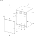
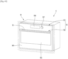
- the present disclosure relates to a home appliance, e.g. a refrigerator, a dish washer, a laundry machine such as a clothing manager or a washing and/or drying machine, or a cooking device, e.g. an oven, having a panel assembly.
- a home appliance e.g. a refrigerator, a dish washer, a laundry machine such as a clothing manager or a washing and/or drying machine, or a cooking device, e.g. an oven, having a panel assembly.
- a refrigerator is a home appliance for storing food at low temperature in an internal storage space that is shielded by a refrigerator door, and is configured to store the stored food in an optimal state by cooling the inside of the storage space using cold air generated through heat exchange with a refrigerant circulating through the refrigeration cycle.
- Such a refrigerator is gradually being enlarged and multi-functional according to a trend of changes in dietary life and high-quality products, and a refrigerator equipped with various structures and convenience devices in consideration of user convenience is being developed.
- U.S. Patent No. 8789900 discloses a structure in which a deco panel forming an outer appearance is installed on a door front of a refrigerator, and here, the outer appearance of the door front is formed according to a user's preference by detachably configuring the deco panel.
- the light emitting member is positioned inward compared with a panel forming a front surface of a door, and thus there is a problem in that an outer appearance is poor due to shadows generated at both ends of the door when a light emitting member is operated.
- Koran Patent No. 10-2018-0067382 discloses a refrigerator in which a light guide plate is provided inside a door and a light emitting diode (LED) is provided below the light guide plate to emit light toward a front surface of the door.
- LED light emitting diode
- An object of the present disclosure is to provide a panel assembly for a home appliance, in particular for a door of a home appliance, and to a home appliance including the same, e.g. a refrigerator, a dish washer, a laundry machine such as a clothing manager or a washing and/or drying machine, or a cooking device, e.g. an oven, wherein an appearance of an entire panel forming a front surface of a door of the home appliance can be modified by a user, e.g. it can glow with color set by a user.
- a refrigerator for causing an entire panel forming a front surface of a door to glow with color set by a user.
- An object of the present disclosure is to provide a panel assembly for a home appliance, in particular for a door of a home appliance, and to a home appliance including the same, e.g. a refrigerator, a dish washer, a laundry machine such as a clothing manager or a washing and/or drying machine, or a cooking device, e.g. an oven, with no bezel and/or with an invisible coupling region of a panel and a light guide plate.
- a refrigerator which include a coupling region of a panel and a light guide plate to transmit light therethrough.
- An object of the present disclosure is to provide a panel assembly for a home appliance, in particular for a door of a home appliance, and to a home appliance including the same, e.g. a refrigerator, a dish washer, a laundry machine such as a clothing manager or a washing and/or drying machine, or a cooking device, e.g. an oven, with a compact, stable and/or invisible mounting structure of a panel forming a front surface (i.e. outer surface) of the panel assembly.
- a refrigerator which include a member for preventing contact between a panel and a light guide plate.
- a home appliance includes: a cabinet forming or defining a space and a door for opening and closing the space, the door including a door body and a panel assembly mounted in front of and/or on and/or at the door body, wherein the panel assembly includes: a lighting device configured to emit light, a panel configured to form a front surface (or outer surface) of the panel assembly and/or of the door and to transmit light therethrough, a light guide plate disposed behind the panel, i.e. at a rear side of the panel, and configured to guide light emitted from the lighting device towards the panel (i.e. towards an entire surface of the panel), and a member disposed between the panel and the light guide plate and configured to transmit light from the light guide plate to or towards the panel.
- the panel assembly includes: a lighting device configured to emit light, a panel configured to form a front surface (or outer surface) of the panel assembly and/or of the door and to transmit light therethrough, a light guide plate disposed behind the panel, i.e. at a
- the panel assembly, the home appliance and/or the refrigerator may include one or more of the following features:
- Directional indications such as front, rear, upper, lower, etc. are to be understood with respect to an operational orientation of the home appliance in a state where the panel assembly is mounted on or at its door.
- the panel assembly may be configured to form an outer appearance of the door, e.g. a front surface of the door.
- the panel assembly may be mountable or mounted on the door, e.g. on a front surface of the door and/or on a door body of the door.
- the home appliance may be any home appliance including a door for opening and closing a space formed in the home appliance.
- the home appliance may be a refrigerator, a cooking device, a dish washer, a laundry machine, a clothing manager, or the like.
- the lighting device may include an LED assembly.
- the lighting device may be disposed on or at a side or an edge of the light guide plate.
- the member is disposed between the panel and the light guide plate for assembling the panel and the light guide plate.
- the member may receive or hold the light guide plate and/or the panel may be attached on or at the member.
- the light guide plate and/or the member may have a size and/or surface area corresponding to that of the panel.
- a reflective sheet may be disposed behind (i.e. at a rear surface of) the light guide plate.
- the reflective sheet may be in surface contact with the light guide, e.g. with a surface of the light guide facing away from the member and/or from the plate.
- the reflective sheet may be configured to reflect light towards the light guide and/or the member and/or the plate.
- the panel assembly may include a back cover forming a rear surface of the panel assembly. Then, the reflective sheet may be disposed between the light guide plate and the back cover.
- a reflective member may be disposed at at least one side surface of the light guide plate, e.g. at at least one of an upper side surface, a lower side surface, and lateral side surfaces (a left side surface and a right side surface).
- the reflective member may be configured to prevent light from being transmitted from a corresponding side of the door.
- the member may be transparent and/or made of plastic.
- the panel may be transparent and/or made of glass or plastic.
- the member includes a front part on which the panel is mounted.
- the front part may have a size and/or surface area corresponding to that of the panel.
- the panel may be attached and/or adhered on the front part of the member.
- the member includes a side part extending rearward, or towards the door body and/or the back cover, from both or opposite ends of the front part to form a space into which the light guide plate is inserted.
- the side part may be formed at right and left side ends of the front part, and right and left side ends of the light guide plate are inserted into the side part to be fixed to the member.
- the side part may include a first part extending towards the door body and a second part extending from the first part.
- the second part may extend from the first part towards a center of the member and/or to face a rear surface of the front part and/or to form a first space with the front part.
- the first part and the second part may form a bracket with the front part to receive the light guide plate therein.
- a first space recessed to allow both ends of the light guide plate to be inserted thereinto may be formed in the side part.
- the side part may extend vertically along the front part.
- the first space may have open upper and lower surfaces through which the light guide plate is inserted vertically.
- the member may be formed with the same cross-sectional shape in a vertical direction.
- the panel assembly or the refrigerator may further include third parts protruding in a direction to face each other from extending ends of the first parts at both sides.
- the upper bracket and the lower bracket may be inserted and mounted in a second space formed by the first part, the second part, and the third part.
- An upper end of the member in particular an upper end of the front part and/or of the side part, is stepped to receive the upper bracket.
- a lower end of the member in particular a lower end of the front part and/or of the side part, is stepped to receive the lower bracket.
- Upper and lower ends of the front part may be formed to be stepped with the side part, the upper bracket may be mounted at an upper end of the side part, and the lower bracket may be mounted at a lower end of the side part.
- the upper bracket may be mounted on an upper end of the side part and inserted into the second space.
- a n upper end of the upper bracket may be at level and/or flush with an upper end of the front part.
- the lower bracket may be mounted below a lower end of the side part and inserted into the second space.
- a lower end of the lower bracket may be at level and/or flush with a lower end of the front part.
- Lateral ends or sides of the upper bracket and/or of the lower bracket may be flush with lateral ends (i.e. outer sides) of the side part.
- the panel may be mounted in front of the front part to cover the front part.
- a light diffuser may be added to the member to diffuse light transmitted through the member and directed toward the panel.
- a direction toward a door is defined as a front direction with respect to a cabinet shown in FIGS. 1 and 2
- a direction toward the cabinet with respect to the door is defined as a rear direction
- a direction toward a bottom on which a refrigerator is installed is defined as a downward direction
- a direction away from the bottom is defined as an upward direction.
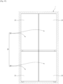
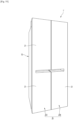
- the door may include a refrigerating compartment door 201 for opening and closing the refrigerating compartment, and a freezing compartment door 202 for opening and closing the freezing compartment.
- the refrigerating compartment door 201 may be referred to as an upper door
- the freezing compartment door 202 may be referred to as a lower door.
- the refrigerating compartment door 201 may include a pair of a left refrigerating compartment door and a right refrigerating compartment door that are arranged side by side.
- the left refrigerating compartment door and the right refrigerating compartment door may open and close the refrigerating compartment while being independently rotated.
- the left refrigerating compartment door and the right refrigerating compartment door may be disposed adjacent to each other and may have the same size.
- a refrigerator having a structure in which a refrigerating compartment is disposed at an upper part and a freezing compartment is disposed at a lower part is described as an example in the embodiment, the present disclosure may be applied to all types of refrigerators equipped with a door without being limited to a type of a refrigerator.
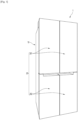
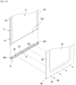
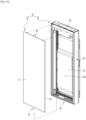
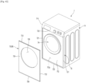
- a front appearance of the refrigerator 1 may be formed in the state in which the door 20 is closed and may form the out appearance of the refrigerator 1 viewed from the front in the state in which the refrigerator 1 is installed.
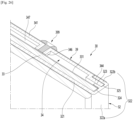
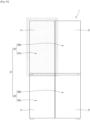
- the door 20 includes a door body 21 forming the overall shape of the door 20, and a panel assembly 30 forming a front appearance of the door 20. That is, the door 20 may be configured in such a way that the panel assembly 30 is mounted on a front surface of the door body 40.
- the door body 40 may include a side deco 44 forming right and left side surfaces of the door body 21.
- the side deco 44 may connect right and left side ends of the body plate 41 and right and left side ends of the door liner 42.
- the door body 40 may include an upper cap deco 43 and a lower cap deco 45 that form upper and lower surfaces of the door body 40.
- the upper cap deco 43 may be connected to an upper end of the side deco 44, an upper end of the body plate 41, and an upper end of the door liner 42.
- the lower cap deco 45 may be connected to a lower end of the side deco 44, a lower end of the body plate 41, and a lower end of the door liner 42.
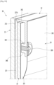
- a rear surface of the panel assembly 30 may be fixed in contact with the body plate 41.
- a lower end of the panel assembly 30 may be caught and restrained with a lower end of the lower cap deco 45, and an upper end of the panel assembly 30 may be coupled to an upper end of a front surface of the upper cap deco 43 to firmly couple the panel assembly 30 to the door body 40.
- the panel assembly 30 may be detachably mounted from the door body 40 for services and maintenance.
- a front surface of the panel assembly 30 may be exposed forward in the state in which the panel assembly 30 is mounted on the door body 40, and the panel assembly 30 may substantially form the front appearance of the door 20.
- the panel assembly 30 may be configured to emit light from an entire front thereof and may be configured to glow with various colors.
- a lighting device 36 may be provided inside the panel assembly 30.
- a wire 381 may be connected to the lighting device 36 in order to supply and control power.
- the wire 381 may be exposed outside the rear surface of the panel assembly 30, and a connector 382 may be provided on an end of the wire 381.
- a structure connected to the connector 382 of the wire 381 to supply power to the lighting device 36 may be provided on a front surface of the door body 40.
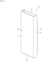
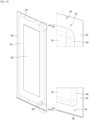
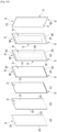
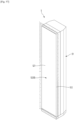
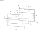
- FIG. 4 is a perspective view of a panel assembly viewed from the rear according to an embodiment of the present disclosure.
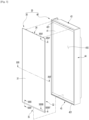
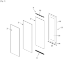
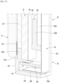
- FIG. 5 is an exploded perspective view of the panel assembly viewed from the front.
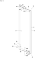
- FIG. 6 is an exploded perspective view of the panel assembly viewed from the rear.
- the panel assembly 30 includes a panel 31 forming a front appearance, the lighting device 36 for emitting light to cause the panel 31 to glow, a light guide plate 33 for guiding light emitted from the lighting device 36, and a member 32 on which the panel 31 is mounted.
- the panel assembly 30 includes an upper bracket 34 forming an upper surface of the panel assembly 30 and a lower bracket 35 forming a lower surface of the panel assembly 30.
- the lighting device 36 may be mounted on the lower bracket 35.
- the panel assembly 30 may further include a back cover 39 forming a rear surface.
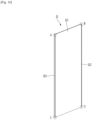
- the panel 31 may be formed in a rectangular plate shape and may be formed of a material that transmits light therethrough.
- the panel 31 may be formed of a glass material such as blue glass, white glass, and vapor deposition glass or may be formed of other materials for transmitting light therethrough, such as ABS, PMMA, or PC.
- the panel 31 may be formed with a set thickness for preventing the panel 31 from breaking easily due to the features of the panel 31 that forms an outer appearance.
- the panel 31 may be formed with a larger thickness than the light guide plate 33.
- the panel 31 may be formed with a thickness of about 3 mm to 5 mm.
- the panel 31 may be referred to as a transparent plate or an out plate.
- the panel 31 is formed to be transparent to allow light reflected by the light guide plate 33 to be transmitted.
- the transparency may be defined as a degree to which the light reflected by the light guide plate 33 is transmitted and irradiated to the outside to identify that the panel 31 glows with specific color.
- the "transparency” and “transmittance” may be defined as the state in which it is possible to cause light to pass through the panel 31 and to represent set color through the panel 31.
- the panel 31 may be formed to have color and may be formed to represent different colors depending on an operation or on and off states of the lighting device 36.
- a specific design or pattern may be printed on the panel 31 to have specific color.
- a film with a specific design or pattern printed thereon may be added to the panel 31, surface treatment such as imprinting, etching, and glass printing may be performed on the panel 21, or a coating or deposition layer having specific color and texture may be formed to form an outer appearance of the panel 31.
- a color layer 311 having color may be formed on the panel 31.
- the color layer 311 may be formed to have at least color having brightness equal to or greater than 0 other than black. That is, in a state in which the refrigerator 1 is installed, the front surface of the refrigerator 1 may be displayed in a color other than black, and the front color of the refrigerator may be changed according to an operation of the lighting device 36.
- the panel 31 may be formed to correspond to a size of a portion of a front surface of the panel assembly 30, which is exposed to the outside.
- an upper end and right and left side ends of the panel 31 except for a lower end may be formed to have the same size as those of the panel assembly 30.
- the lower end of the panel 31 may be positioned somewhat higher than the lower end of the panel assembly 30, that is, the lower end of the lower bracket 35, but the exposed portion of the lower bracket 35 may be shielded by the lower cap deco 45 in the state in which the panel assembly 30 is mounted.
- the entire front surface of the panel 31 which is exposed to the outside in the state in which the panel assembly 30 is mounted may be formed by the panel 31.
- the panel 31 may be formed to be larger than the light guide plate 33.
- a rear surface of the panel 31 may be coupled to a front surface of the member 32.
- a separate component is not present at the perimeter of the panel 31, and the panel 31 may form the front appearance of the panel assembly 30.
- the light guide plate 33 may be positioned at a rear spaced apart from the panel 31 and may be configured to guide light emitted from the lighting device 36 disposed at the upper end of the light guide plate 33 forward.
- the light guide plate 33 may be formed of transparent acrylic, plastic, or a transparent polymer material.
- the light guide plate 33 may have a light diffuser added thereto for diffusing light incident on the light guide plate 33 or a pattern for diffusing light may be further formed on the light guide plate 33.
- light may be transferred to the panel 31 by the light guide plate 33, and in this case, a pattern of the light guide plate 33 may be set to cause the entire front surface of the panel 31 to glow with uniform brightness.
- the light guide plate 33 may be entirely formed in a rectangular plate shape and may be formed with a somewhat smaller size than that of the panel 31.
- the light guide plate 33 may be supported by the back cover 39 from the rear and may be fixed to be maintained at a predetermined interval from the panel 31 by the member 32.
- the light guide plate 33 may be formed with a set thickness to reflect light emitted from the lighting device 36 toward the panel 31.
- the light guide plate 33 may have a thickness for providing the amount of light to cause the entire panel 31 to sufficiently glow.
- the panel 31 is formed with a thickness of about 3.2 mm
- the light guide plate 33 may be formed with a thickness of about 2 mm.
- the member 32 is disposed between the panel 31 and the light guide plate 33.
- the member 32 may be used to fixedly mount the light guide plate 33 and the panel 31, and in particular, may maintain the light guide plate 33 at a predetermined interval from the panel 31.
- the front surface of the member 32 may support the panel 31 and opposite side surfaces of the member 32 may restrain both ends of the light guide plate 33.
- the front surface of the member 32 may be somewhat larger than the size of the light guide plate 33, and in the state in which the light guide plate 33 is mounted, the front surface of the member 32 and the light guide plate 33 may be maintained in the state of surface-contacting each other.
- the member 32 includes a front part 321 shaped like a plate on which the panel 31 is mounted, and a side part 322 that is formed at right and left side ends of the front part 321 and on which the light guide plate 33 is mounted.
- the front part 321 may be formed like a plate corresponding to the panel 31, and a front surface of the light guide plate 33 may be disposed on a rear surface of the front part 321.
- the side part 322 extends may extend rearward from right and left side ends of the front part 321 and may be formed to restrain right and left side ends of the light guide plate 33.
- the member 32 is used to mount the panel 31 and the light guide plate 33 thereon and may be referred to as a support member, the member 32 may transmit light therethrough and may be referred to as a transmissive plate, and the member 32 may form a structure containing a side surface of the panel assembly 340 and may also be referred to as a frame.
- the member 32 is formed of a material for transmitting light therethrough and may be entirely formed by injection or extrusion as a single component. That is, the member may be formed of a material having a property of transmitting light and having moldability. For example, the member 32 may be formed of an optically transparent ABS material. The member may be formed of various transparent plastic materials, that is, a material such as polycarbonate (PC), or acrylic. The member may transmit light reflected by the light guide plate 33 therethrough to make the light pass through the panel 31.
- PC polycarbonate
- the light transmission capability and transparency of the member 32 may refer to a degree to which light emitted from the light guide plate 33 at the rear is capable of passing through the member 32 to illuminate the panel 31.
- the member 32 may have corrosion or a pattern formed on the front part 321 through which light is transmitted, and such corrosion or pattern may be formed when viewed from the front of the panel assembly 30.
- a light diffuser may be added during molding of the member 32.
- the light diffuser may diffuse light passing through the member 32 and may allow the light to be emitted more evenly to the entire front of the panel 31. In particular, it may be possible to prevent a lower portion of the panel 31, adjacent to the lighting device 36, from locally brightening or a hot spot from appearing.
- the member 32 may make the entire panel 31 brighter through light diffusion, but the transparency of the member 32 may be slightly lowered, and transmission of light reflected from the light guide plate 33 may be sufficient.
- an outline of the light guide plate 33 disposed behind the member 32, a boundary of the side part 322 of the member 32, and the like may be hidden and may not be exposed to the outside. That is, due to the member 32, a rear appearance of the panel assembly 30 may be formed by the panel 31 and an internal boundary or hidden parts may not be seen to the outside.
- the upper bracket 34 is provided at an upper end of the panel assembly 30.
- the upper bracket 34 forms an upper surface of the panel assembly 30.
- the upper bracket 34 may be injection-molded with a plastic material, and may form a structure coupled to the member 32 and a structure coupled to the back cover 39.
- the back cover 39 may be coupled to the rear surface of the upper bracket 34.
- the back cover 39 may be coupled to the upper bracket 34 by fastening a screw.
- the rear surface of the light guide plate 33 may be supported by the front surface of the upper bracket 34. That is, when the back cover 39 is coupled, the upper bracket 34 may support the light guide plate 33 from the rear.
- the lower bracket 35 is provided at the lower end of the panel assembly 30.
- the lower bracket 35 forms a lower surface of the panel assembly 30.
- the lower bracket 35 may be injection-molded with a plastic material and may form a structure coupled to the member 32 and a structure coupled to the back cover 39.
- the back cover 39 may be coupled to the rear surface of the lower bracket 35.
- the back cover 39 may be coupled to the lower bracket 35 by fastening a screw.
- the rear surface of the light guide plate 33 may be supported by the front surface of the lower bracket 35. That is, when the back cover 39 is coupled, the lower bracket 35 may support the light guide plate 33 from the rear.
- right and left side ends of the light guide plate 33 may be fixed by the member 32, and the upper and lower ends of the light guide plate 33 may be supported by the upper bracket 34 and the lower bracket 35 from the rear.
- the lighting device 36 may be mounted on the lower bracket 35.
- the lighting device 36 may be configured to emit for determining the front color and brightness of the panel assembly and to emit light toward the light guide plate 33.
- the lighting device 36 may be provided inside the lower bracket 35 and may be assembled and mounted with the lower bracket 35 in the state of being mounted on the lower bracket 35.
- a cover perimeter part 392 which form a perimeter of the back cover 39, may be in contact with the side part 322 of the member 32, and upper and lower ends of the cover perimeter part 392 may be in contact with the upper bracket 34 and the lower bracket 35, respectively.
- a plurality of screws 399 may be coupled to the upper and lower ends of the cover perimeter part 392 and may be coupled to the upper bracket 34 and the lower bracket 35 through the back cover 39 to fixedly mount the back cover 39.
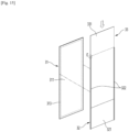
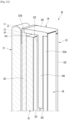
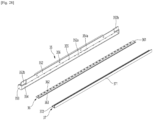
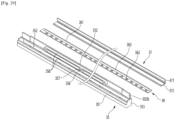
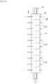
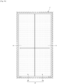
- FIG. 7 is an exploded perspective view showing a coupling structure of a light guide plate, a reflective sheet, and a reflective member as one component of the panel assembly.
- the light guide plate 33 may be formed in a rectangular plate shape.
- the light guide plate 33 may be formed with a size corresponding to or somewhat smaller than the size of the front part 321 of the panel 31 and the member 32.
- the light guide plate 33 may be formed with a thickness to be inserted into a side surface of the member 32, and in the state in which the light guide plate 33 is mounted on the member 32, a front surface of the light guide plate 33 may be in completely in contact with a rear surface of the front part 321 of the member 32, and thus a gap may not be generated therebetween.
- the light guide plate 33 may be formed to reflect light of the lighting device 36, emitted from below, along the light guide plate 33 and to uniformly transfer the light forward, that is, to an entire surface of the panel 31.
- a pattern for reflecting light emitted along the light guide plate 33 forward may be formed on the light guide plate 33.
- the light guide plate 33 may be formed in such a way that the density of the pattern increases upward based on the center of the light guide plate 33 and the density of the pattern increases to the right and left sides from the center, and thus the overall brightness may be uniform.
- the pattern may be formed with a width of about 10 mm to 20 mm at an upper end and both side ends of the light guide plate 33 except for a lower end thereof.
- Pattern of a perimeter of the light guide plate 33 may have a different shape from a pattern of a central part of the light guide plate 33, thereby further improving light collection capability at the perimeter of the light guide plate 33.
- the reflective sheet 331 may be coated or patterned to cause a front surface thereof to reflect light, and the front surface of the reflective sheet 331 may be in contact with the rear surface of the light guide plate 33. Thus, light moved along the reflective sheet 331 may be reflected by the front surface of the reflective sheet 331 to be directed forward and may be reflected to the panel 31.
- An edge reflector 331a may be further formed on the reflective sheet 331.
- the edge reflector 331a may be formed along a position corresponding to the adhesive member 313.
- the edge reflector 331a may be formed along the right and left side ends and the upper end of the reflective sheet 331, and the adhesive member 313 may be disposed in a region of the edge reflector 331a.
- the region of the edge reflector 331a may have higher reflectance than the other part of the reflective sheet 331.
- a pattern with higher density or a pattern with higher reflectance than the other part of the reflective sheet 331 may be formed on the edge reflector 331a.
- the edge reflector 331a of the reflective sheet 331 may have higher light collection capability and reflectance than the other part and may allow light to be transmitted through the adhesive member 313 to illuminate the panel 31. That is, although the adhesive member 313 is provided, the panel 31 may entirely glow with uniform brightness.
- the edge reflector 331a and the pattern part 333 may be formed together, and in this case, the edge reflector 331a and the pattern part 333 may have the same arrangement and the same width. As necessary, only any one of the edge reflector 331a and the pattern part 333 may be formed.
- a reflective member 332 may be further provided along an outer perimeter of the light guide plate 33.
- the reflective member 332 may be formed of the same material as that of the reflective sheet 331 and may direct light leaking through a perimeter surface of the light guide plate 33 again into the light guide plate 33 to further increase the reflection efficiency of the light guide plate 33.
- Light leaking to the outside through a perimeter of the light guide plate 33 may be blocked by the reflective member 332, and thus light may also be prevented from leaking to the outside through the side part 322 of the member 32 formed of a transparent or translucent material, which is adjacent to an end of the light guide plate 33.
- the reflective member 332 may be adhered to a perimeter of an outer surface of the light guide plate 33 by a tape or an adhesive, and a surface on which a pattern for reflecting light into the light guide plate 33 is formed may be adhered to a perimeter surface of the light guide plate 33.
- the member 32 may be entirely formed by injection molding of a resin material and may be formed of a transparent material, and thus light reflected forward through the light guide plate 33 may be transmitted and directed toward the panel 31.
- the front part 321 may be formed like a plate having a size corresponding to the panel 31, and the adhesive member 313 may be coated on the perimeter of the front part 321 to adhere the panel 31 to the member 32.
- the adhesive member 313 may be formed of a transparent or light-transmissive material, and the entire region of the panel 31, which contains a region on which the adhesive member 313 is coated, may glow.
- the right and left width of the front part 321 may be formed to have the same width as the right and left width of the panel 31.
- An upper end of the front part 321 may be positioned at a position corresponding to an upper end of the panel 31, and a lower end of the front part 321 may be positioned at a higher position than a lower end of the panel 31. That is, the remaining end of the front part 321 except for a lower end may be formed to correspond to a shape of the panel 31 and thus may entirely correspond to the size and shape of the panel 31.
- the sealant 313 may be formed of a transparent or light-transmissible material, and the panel 31 may be configured in such a way that an entire area including an area to which the sealant 313 is applied shines.
- the sealant 313 may be formed of a polyurethane resin having excellent thermal insulation performance as a main resin.
- the main resin means that the polyurethane resin exceeds 50% by weight based on the total weight of components forming the sealant as 100% by weight.
- the sealant 313 may have a density measured according to ASTM D 972 of 0.5 to 1.5 g/cm3, in detail, 1.1 to 1.3 g/cm3.
- the sealant 313 may be coated on the panel 31 or the member 32, and may be transparent or opaque in a cured state, and a color may also use a white series or a black series, but is not limited thereto.
- the panel 31 may be formed to implement a specific color or pattern. That is, the panel 31 may be formed in such a way that light emitted from the lighting device 36 passes through the panel 31 to realize a color and that a specific color is also realized even when the lighting device 36 is turned off.
- the sealant 313 may be advantageously hidden by the color of the panel 31.
- the sealant 313 may be compressed. That is, the sealant 313 may be uniformly distributed on a surface of the panel 31 in a state in which the panel 31 and the member 32 are coupled, and thus light emitted from the lighting device 36 may be uniformly transmitted.
- a liquefied sealant may be compressed and spread while the front plate and the support member are fixed, and a boundary between the sealant 313 and the panel 31 may become unclear. Accordingly, advantageously, a boundary line between the sealant 313 and the panel 31 may not be visible from the front of the panel 31.
- the sealant 313 may be cured in a state of being coupled to the member 32.
- the width of the sealant 313 is greater than 9 mm, the amount of light transmitted through the panel 31 may be reduced by the sealant 313, and a portion coated with the sealant 313 may be darker than a portion that is not coated with the sealant 313.
- the sealant 313 may be coated on an area of about 1 to 5%, in detail, 2 to 4% based on 100% of the total area of a rear surface of the panel 31 or a front surface of the member 32. Within this range, it may be possible to prevent the panel 31 and the member 32 from being separated and to prevent light transmission from being blocked by the sealant 313.
- a difference in light transmission between a portion of the panel 31, which is coated with the sealant 313, and a portion of the panel 31, which is not coated with the sealant 313, may be less than 10%, in detail, less than 5%, in more detail, less than 3%.
- a difference in brightness between a portion of the panel 31, which is coated with the sealant 313, and a portion of the panel 31, which is coated with the sealant 313, may be less than 10%, in detail, less than 5%, in more detail, less than 3%.
- An inner end of the sealant 313 coated on both side surfaces of the panel 31 or the member 32 may be positioned between a second part 323 and a third part 322b of the member 32.
- the inner end of the sealant 313 may extend more inward than the inner end of the second part 323.
- the inner end of the sealant 313 may be positioned outside the inner end of the third part 322b of the member 32.
- the term 'inner' may refer to an end corresponding to a direction in which the sealant 313 extends from the member 32 based on a view of the member 32 from the front.
- a horizontal length of the sealant 313 coated on both side surfaces of the panel 31 or the member 32 may be approximately larger than a length by which the second part 323 of the member 32 extends more inward than a first part 322a.
- a horizontal length of the sealant 313 coated on both side surfaces of the panel 31 or the member 32 may be approximately shorter than a length by which the third part 322b of the member 32 extends more inward than the first part 322a.
- the front of the door 20 may glow uniformly when the lighting device 36 is turned on.
- a difference in light transmittance between a portion coated with the sealant 313 and a portion that is not coated with the sealant 313 may be 10% or less.
- the sealant 313 coated on an upper end of the member 32 may be positioned above an upper end of a support rib 347.
- An upper end of the sealant 313 coated along the upper end of the member 32 may be positioned below the upper end of the upper bracket 34 and may be positioned below an upper end of the panel 31.
- the sealant 313 coated on a lower end of the member 32 may be coated up to, for example, a position at which the lower end of the sealant 313 corresponds to the lower end of the lower bracket 35.
- the panel 31 and the upper end of the member 32 may be firmly adhered while an area coated with the sealant 313 is minimized.
- the panel 31 or the member 32 may not require a concave groove for guiding a position to which the sealant 313 is applied or for preventing the sealant 313 from being moved after being attached to the panel 31 or the member 32.
- an operation of assembling the panel 31 and the member 32 may be advantageously simplified.
- sealant 313 is coated only on the rear surface of the panel 31, a separate coupling member and coupling structure such as a screw may not be required in order to mount the panel 31 on the door body 40.
- an entire front surface of the panel 31, which is exposed to the outside in the state in which the panel assembly 30 is mounted, may be defined by the panel 31.
- an edge of the front surface of the panel assembly 30 may be positioned to correspond to an edge of the panel 31. That is, the panel 31 may define a front appearance of the door 20, and when a user views the door 20 from the front, there is no portion covering a periphery of the door 20, and thus an improved outer appearance may be provided.
- the sealant 313 is coated between the panel 31 and the member 32
- the present disclosure is not limited thereto.
- the sealant 313 may be directly coated between the panel 31 and the light guide plate 33.
- the front part 321 may have a structure for connecting the side parts 322 at right and left sides. That is, the front part 321 may be continuously formed between the side parts 322, and the side part 322 at one side may extend to the side part 322 at the other side.
- the panel 31 may be adhered to the front part 321 by the adhesive member 313.
- the panel 31 may be indirectly coupled to the front part 321 by the front part 321 and the adhesive member 313, and this may be considered as the state of being spaced apart from the front part 321.
- the light guide plate 33 may be disposed to be in contact with the rear surface of the front part 321.
- the front surface of the light guide plate 33 and the rear surface of the front part 321 may be in contact with each other, but may be in simple contact with each other rather than being completely adhered or attached to each other.
- the side part 322 may be formed along the right and left side ends of the light guide plate 33.
- the side part 322 may be stepped with upper and lower ends of the light guide plate 33 and may be formed to match with side ends of the upper bracket 34 and the lower bracket 35.
- the side part 322 may include a first part 322a extending rearward from the right and left side ends of the front part 321 and a second part 323 protruding to face each other in an internal surface of the first part 322a at both ends.
- the side part 322 may further include a third part 322b at an end of the first part 322a. That is, the side part 322 may include the first part 322a and the second part 323, and as necessary, may further include the third part 322b.
- the third part 322b may be bent inward from an extending end of the first part 322a. That is, one pair of the third parts 322b that are formed on one pair of the first parts 322a, respectively, may extend to face each other.
- the second part 323 may be positioned between the right and left side ends of the light guide plate 33 and the right and left side ends of the lower bracket 35. That is, the second part 323 may be provided at the rear based on the light guide plate 33 and may be positioned at the front based on the right and left side ends of the upper bracket 34 and the lower bracket 35.
- the second part 323 may be positioned between the front part 321 and the third part 322b and may be formed in parallel to the front part 321 and the third part 322b.
- the second part 323 may partition a space between the front part 321 and the third part 322b to form a first space 324 into which the light guide plate 33 is inserted, and a second space 325 into which the upper bracket 34 and the lower bracket 35 are inserted.
- the first space 324 may be formed between the front part 321 and the second part 323.
- a front-to-rear distance of the first space 324 may be formed with a size corresponding to the thickness of the light guide plate 33.
- the light guide plate 33 may be slidably inserted along the side part 322, and thus may not be in close contact with the rear surface of the front part 321, and accordingly, a fine gap may be formed and the light guide plate 33 may be slidably inserted thereinto. That is, the front part 321 and the light guide plate 33 may be in contact with each other without being limited thereto, and at least a portion of the light guide plate 33 may be spaced apart from the front part 321.
- the lower end of the light guide plate 33 may be positioned to face the lighting device 36.
- the light guide plate 33 may be disposed on the same extension line as the light source 362 of the lighting device 36, and in the state in which the light guide plate 33 is fixedly inserted into the first space 324, movement in forward and backward directions of the light guide plate 33 may be restrained.
- the light guide plate 33 may be in contact with the front part 321, may be maintained at a predetermined interval from the panel 31, and may not deviate from a position at which the light guide plate 33 is originally installed.
- the state in which the light guide plate 33 is disposed on the same extension line as the light source 362 included in the lighting device 36 may be maintained, and thus it may be possible to ensure that light emitted from the light source 362 is directed toward an end of the light guide plate 33.
- the upper and lower ends of the side part 322 may be formed lower than the upper and lower ends of the front part 321, and the upper and lower ends of the side part 322 may be stepped based on the upper end of the front part 321.
- an upper end protrusion 321b and a lower end protrusion 321a that further protrude compared with the upper and lower ends of the side part 322 may be formed on the upper and lower ends of the front part 321.
- the upper bracket 34 and the lower bracket 35 that are mounted on the upper and lower ends of the member 32 may be assembled with directivity to prevent misassembly, and the upper bracket 34 and the lower bracket 35 may be more firmly and fixedly mounted.
- the upper bracket 34 when the upper bracket 34 is mounted, right and left sides of the upper bracket 34 may be supported by the upper end of the side part 322, and a front end of the upper bracket 34 may be supported by the upper end protrusion 321b.
- the upper bracket 34 may be simultaneously supported by the side part 322 and the front part 321 and may also have a temporary fixed structure even before the screws 399 is coupled.
- the upper bracket 34 In the state in which the upper bracket 34 is completely mounted, the upper bracket 34 may be coupled to the front part 321 and the side part 322 to be prevented from being distorted or deformed.
- the upper bracket 34 and the lower bracket 35 may be inserted into the second space 325, and simultaneously, may be accommodated on a stepped portion of the upper and lower ends of the side part 322 and the front part 321 to be firmly coupled to the member 32.
- the upper and lower ends of the panel assembly 30 may be formed.
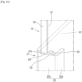
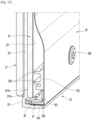
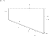
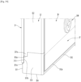
- FIG. 15 is a diagram showing a coupling structure of the member, the panel, and the light guide plate.
- FIG. 16 is an enlarged view of a part "E" of FIG. 15 .
- FIG. 17 is an exploded perspective view taken along XVII-XVII' of FIG. 3 .
- the member 32 may be used to mount the panel 31 on the front part 321 and to mount the light guide plate 33 on the side part 322. That is, it may be possible to mount the panel 31 and the light guide plate 33 by a single component of the member 32.
- the panel 31 and the light guide plate 33 may be spaced apart in forward and rearward directions across the member 32 therebetween, and in this case, an interval between the panel 31 and the light guide plate may be maintained by as much as the thickness of the front part 321.
- the member 32 may have the same cross-sectional structure in a vertical direction and thus may be simply molded by extrusion. Simultaneously, provided may be a structure for mounting the panel 31 and the light guide plate 33 using the front part 321 and the side part 322 that are formed by extrusion. Through the structure of the side part 322, even the upper bracket 34 and the lower bracket 35 may be mounted.
- the front part 321 may have a size corresponding to the panel 31, and at least an upper end and a right and left side ends of the front part 321 may be formed in a plate shape corresponding to the right and left side ends of the panel 31.
- the adhesive member 313 for adhering the panel 31 to the front part 321 may be provided on a perimeter of a bottom surface of the panel 31.
- the adhesive member 313 may be formed along an entire perimeter of the panel 31, and the panel 31 may be firmly fixed to the front surface of the front part 321.
- the front surface of the panel assembly 30 may be formed by the panel 31, and any structure for fixing the panel 31 and the light guide plate 33 may not be exposed. That is, the front surface of the panel assembly 30 may be formed by the panel 31, and the entire portion of the panel 31 may glow without a bezel or fixed structure to form an outer appearance of the entire front surface of the panel assembly 30 or the door 20.
- the adhesive member 313 may be formed of a transparent or translucent material to transmit light reflected from the light guide plate 33 therethrough.
- the adhesive member 313 may be formed by coating a transparent or translucent sealant and may be formed by an adhesive such as a transparent or translucent double-side tape.
- the side part 322 may protrude rearward from the right and left side ends of the front part 321, and one pair of the side parts 322 may be opened to face each other.
- the side part 322 may be opened in a vertical direction, and the light guide plate 33 may be inserted into the side part 322 through an insertion space while being slidably moved in a vertical direction.
- the insertion space of the light guide plate 33 may be formed between the rear surface of the front part 321 and the third part.
- the light guide plate 33 may be inserted into the side part 322 in the state being in contact with the rear surface of the front part 321, and in the state in which the light guide plate 33 is in completely contact with the rear surface, the front surface of the light guide plate 33 may be in contact with the rear surface of the front part 321.
- the reflective sheet 331 may be disposed on a rear surface of the light guide plate 33, and in the state in which the reflective member 332 is attached to the remaining perimeter surface except for a bottom surface, the light guide plate 33 may be inserted into the first space 324.
- both ends of the reflective sheet 331 may be accommodated inside the first space 324, and the reflective sheet 331 at right and left side surfaces of the light guide plate 33 may be accommodated therein.
- the reflective sheet 331 may prevent light from leaking the outside through the side part 322.
- the pattern part 333 of the light guide plate 33 and the edge reflector 331a of the reflective sheet 331 may be arranged at a position corresponding to a region in which the adhesive member 313 is disposed. That is, at least the adhesive member 313 may be positioned in an internal region of the pattern part 333 and/or the edge reflector 331a.
- the panel 31 may glow with uniform brightness and color without shadow due to the adhesive member 313.
- the back cover 39 may include the cover protrusion 391 that entirely protrudes forward, and the cover perimeter part 392 formed along a perimeter of the cover protrusion 391.
- a space may be formed between a rear surface of the panel assembly 30 and a front surface of the door body 40. That is, when heat generated during an operation of the lighting device 36 conducted along the rear surface of the panel assembly 30, i.e., the back cover 39 is transferred through the back cover 39, a space for heat dissipation through the rear surface of the panel assembly 30 may be formed.
- a buffer member 393 may be further provided on the cover protrusion 391.
- the buffer member 393 may be formed of an elastically deformable material and may be formed in the form of a sheet to be attached to the cover protrusion 391.
- the buffer member 393 may be formed of an expandable material or a foaming material and may be in close contact with the light guide plate 33 to support the light guide plate 33.
- the buffer member 393 may prevent the light guide plate 33 from shaking and alleviate impact transferred to the light guide plate 33 to protect the light guide plate 33. Even when the light guide plate 33 is deformed while being compressed or expanded by heat, a space in which the light guide plate 33 is deformable may be provided.
- a wire entrance 398 through which the wire 381 connected to the lighting device 36 enters and exits may be formed at one corner of the cover protrusion 391.
- the cover perimeter part 392 may be formed along the perimeter of the cover protrusion 391.
- the cover perimeter part 392 may form a perimeter surface of the back cover 39, that is, upper and lower ends and right and left side ends of the back cover 39.
- a width of the cover perimeter part 392 may be formed to be longer than at least a width of the third part 322b and lengths of the upper bracket front part 341 and the lower bracket front part 351.
- right and left side ends of the cover perimeter part 392 may be supported by the third part 322b of the member 32, and the upper end and the lower end may be coupled to the upper bracket 34 and the lower bracket 35, respectively.
- the cover perimeter part 392 and the cover protrusion 391 may be conned to each other by a cover connector 394.
- the cover connector 394 may be inclined or rounded in a forward direction from the cover perimeter part 392 toward the cover protrusion 391. Load applied to the cover protrusion 391 may be distributed by the cover connector 394.
- a cover screw hole 397 may be formed in upper and lower ends of the cover perimeter part 392.
- the cover screw holes 397 may be coupled to fasten the screws 399 for mounting the back cover 39, and the plurality of cover screw holes 397 may formed at a predetermined interval along the upper and lower ends of the cover perimeter part 392.
- the cover screw holes 397 may be formed at positions corresponding to bracket screw holes 346 and 356 formed in the upper bracket 34 and the lower bracket 35.
- a protrusion opening 395 may be formed on an upper end of the cover perimeter part 392, that is, an upper end of the back cover 39.
- the protrusion opening 395 may be formed to cause a mounting protrusion 343 protruding on the upper bracket 34 to pass therethrough in order to mount the panel assembly 30.
- the protrusion opening may be formed to be recessed downward from the upper end of the back cover 39 and may be cut to cause the mounting protrusion 343 to pass therethrough.
- the protrusion openings 395 may be formed with the number corresponding to the positions of the mounting protrusions 343, and the plurality of protrusion openings 395 may be arranged at a predetermined interval along the upper end of the back cover 39.
- a cover bent part 396 may be formed on a lower end of the cover perimeter part 392, that is, a lower end of the back cover 39.
- the cover bent part 396 may be inserted into the lower cap deco 45 and may be in contact with a right supporter 37 that supports the lighting device 36. Heat of the lighting device 36 transferred through the right supporter 37 may be transferred to the entire of the back cover 39.
- the cover bent part 396 may extend forward vertically from the lower end of the cover perimeter part 392 and may extend from a left side end of the back cover 39 to a right side end thereof.
- the cover bent part 396 may extend with an extension length to be in contact with a lower surface of the right supporter 37.
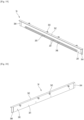
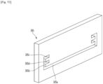
- FIG. 19 is a perspective view of an upper bracket as one component of the panel assembly viewed from the front.
- FIG. 20 is a perspective view of the upper bracket viewed from the rear.
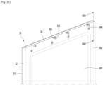
- FIG. 21 is a partial enlarged view showing a shape of an upper part of a panel assembly in the state in which the upper bracket is coupled to the panel assembly.
- FIG. 22 is an exploded perspective view showing a coupling structure of the member, an upper bracket, and a back cover.
- FIG. 23 is a perspective view taken along XXIII-XXIII' of FIG. 21 .
- FIG. 24 is an exploded perspective view taken along XXIV-XXIV' of FIG. 3 .
- FIG. 25 is an exploded perspective view taken along XXV-XXV' of FIG. 4 .
- FIG. 26 is an exploded perspective view taken along XXVI-XXVI' of FIG. 3 .
- the upper bracket 34 may have a length corresponding to the right and left direction length of the panel assembly 30.
- the upper bracket 34 may broadly include the upper bracket front part 341 and an upper bracket upper part 342.
- An upper side part 344 stepped forward may be formed on right and left side ends of the upper bracket front part 341.
- the upper side part 344 may be stepped with a front part of the upper bracket and may be positioned at the front based on the upper bracket front part 341.
- the mounting protrusion 343 protruding rearward may be formed on the rear surface of the upper bracket front part 341.
- the mounting protrusion 343 may be used to mount the panel assembly 30 and may protrude by a predetermined length on the upper bracket front part 341 to be coupled to a protrusion mount 431 of the upper cap deco 43.
- the plurality of mounting protrusions 343 may be formed at a predetermined interval along the upper bracket 34 and may be formed at positions corresponding to the protrusion openings 395.
- the mounting protrusion 343 may protrude from an upper end of the rear surface of the upper bracket front part 341. Thus, when the back cover 39 is mounted, the mounting protrusion 343 may protrude through the protrusion opening 395 of the back cover 39.
- the upper bracket boss 346 may protrude forward and may protrude to a position that is in contact with the rear surface of the light guide plate 33. Thus, when the upper bracket 34 is mounted, a protruding end of the upper bracket boss 346 may support the light guide plate 33 from the rear. That is, when the panel assembly 30 is assembled, the upper bracket 34 may support the upper end of the light guide plate 33 from the rear.
- the support rib 347 at an upper part among one pair of the support ribs 347 may extend to connect upper ends of the plurality of upper bracket bosses 346, and the support rib 347 at a lower part among one pair of the support ribs 347 may extend to connect lower ends of the plurality of upper bracket bosses 346.
- the support ribs 347 may protrude with the same height as a protruding height of the upper bracket boss 346. Thus, when the panel assembly 30 is assembled, the support ribs 347 may support the light guide plate 33 from the rear with the upper bracket boss 346.
- the upper bracket upper part 342 may extend forward on the upper end of the upper bracket front part 341.
- the front end of the upper bracket upper part 342 may extend to be in contact with the front part 321 of the member 32.
- the right and left side ends of the upper bracket upper part 342 may be accommodated on the stepped upper end of the side part 322 of the member 32.
- the upper end of the upper bracket 34 may be positioned at the same height L2 as the upper end of the member 32.
- upper ends of the upper bracket 34 and the member 32 may be formed lower than a height L1 of the upper end of the panel 31.
- components behind the panel 31 may not protrude toward the upper end of the panel 31 and an front appearance may be formed by the panel 31. That is, an outer appearance of the entire front surface of the door 20 may be formed by color represented by the panel 31.
- the upper bracket 34 may be inserted downward from an upper part through an open upper surface of the bracket insertion space 325.
- the upper bracket front part 341 may be positioned inside the member 32 and may be positioned between the side parts 322 at both left and right sides.
- both left and right ends of the upper bracket front part 341, that is, the upper side parts 344 may be inserted into the bracket insertion space 325 to fixedly mount the upper bracket 34 to the upper end of the member 32.
- the upper bracket upper part 342 may be accommodated on the upper end of the side part 322.
- the front end of the upper bracket upper part 342 may be hidden by the upper end protrusion 321b protruding upward from the upper end of the front part 321.
- the upper side part 344 is inserted into the bracket insertion space 325 positioned behind the light guide plate 33, no shading may be generated on the panel 31 when light is reflected by the light guide plate 33. That is, the upper bracket 34 may not be exposed out of the panel 31 in the state of being fixedly mounted on the member 32 and may not block light reflected by the light guide plate 33.
- the lower bracket 35 may have a corresponding to the right and left direction length of the panel assembly 30.
- the lower bracket 35 may broadly include the lower bracket front part 351, a lower bracket rear part 352, a lower bracket side part 353, and a lower bracket lower part 354.
- the lower bracket front part 351 form a shape of the front surface of the lower bracket 35 and may support the panel 31. A portion of the lower bracket front part 351 may protrude below the panel 31 and may be inserted into the lower end of the door body 40, that is, the lower cap deco 45 to fix the lower bracket 35.
- the lower bracket front part 351 may include a bracket stepped part.
- the bracket stepped part may include a first stepped part 351a for supporting a lower end of the panel 31 and a second stepped part 351b for supporting the panel 31 from the rear.
- the first stepped part 351a may be stepped rearward on the front surface of the lower bracket front part 351, and the second stepped part 351b may extend upward from the rear end of the first stepped part 351a.
- the adhesive member 313 may be coated on the second stepped part 351b, and thus the panel 31 may be firmly fixed.
- the upper end of the second stepped part 351b may be coupled to the lower end of the member 32, and thus the front surface of the second stepped part 351b and the front part 321 of the member 32 may be positioned on the same plane.
- the second stepped part 351b may support the panel 31, and simultaneously, may prevent the lighting device 36 or a lighting spot (which may also be referred to as light formation or a hot spot) generated by the lighting device 36 from being exposed.
- the second stepped part 351b may protrude above an upper end of a light source of the lighting device 36 and may protrude with a set height to prevent the lighting device 36 from being exposed forward.
- the second stepped part 351b may hide a region generated due to intensive light irradiation at the lower end of the light guide plate 33 and the lower end of the panel 31, which are very adjacent to the lighting device 36, to prevent a lighting spot from being formed on the panel 31.
- the second stepped part 351b may be formed to be transparent or translucent, and as necessary, may be formed with specific color. Thus, the second stepped part 351b may also be referred to as a shield.
- the lower bracket side part 353 may form a side surface of the lower bracket 35 and may protrude above the lower bracket front part 351.
- the lower bracket side part 353 may protrude above the second stepped part 351b, and thus a stepped portion of a lower end of the side surface of the member 32 may be coupled to engage each other with the lower bracket front part 351 and the lower bracket side part 353.
- the lower bracket rear part 352 may be formed on a rear end of the lower bracket side part 353.
- the lower bracket rear part 352 may form a rear surface of the lower bracket 35 and may fixedly mount the lower bracket 35 on the member 32.
- the lower bracket rear part 352 may be formed in parallel to the panel 31 and the light guide plate 33 and may extend in a vertical direction. A rear surface part of the lower bracket 35 may protrude above the lower bracket front part 351 and the lower bracket side part 353.
- a lower side part 352b stepped forward may be formed on right and left side ends of the lower bracket rear part 352.
- the lower side part 352b may be stepped with the lower bracket rear part 352 and may be positioned in the front of the lower bracket front part 351.
- the lower side part 352b may be formed with a thickness corresponding to the width of the second space 325 and may be slidably inserted upward from a lower part of the second space 325.
- the lower support 358 protruding on the front surface of the lower bracket rear part 352 may support a lower end of the rear surface of the light guide plate 33 or a lower part close to the lower end.
- the lower bracket boss 357 may protrude forward and may protrude to be in contact with the rear surface of the light guide plate 33. Thus, when the lower bracket 35 is mounted, a protruding end of the lower bracket boss 357 may support the light guide plate 33 from the rear. That is, when the panel assembly 30 is assembled, the lower bracket 35 may support the upper end of the light guide plate 33 from the rear.
- the lower support 358 may be formed to connect the plurality of lower bracket bosses 357, and thus may entirely support the lower end of the light guide plate 33.
- the lower support 358 may be formed as a pair of ribs spaced apart up and down to more stably support the light guide plate 33 from the rear.
- the lower support 358 may connect the plurality of lower bracket bosses 357 to reinforce the strength of the lower bracket 35.
- the lower bracket boss 357 may protrude at the same height as the lower support 358, and thus the lower bracket boss 357 may support the lower end of the light guide plate 33 from the rear with the lower support 358. As such, the lower part of the light guide plate 33 may be supported only by the structure in which the lower bracket 35 is inserted into the member 32.
- a bracket opening may be formed in the lower bracket rear part 352.
- the bracket opening 352a may extend from a left side end of the lower bracket rear part 352 to a right side end and may be formed at a position facing the lower bracket front part 351.
- a bracket rib 354a for supporting the lighting device 36 or the right supporter 37 from below may be formed on the lower bracket lower part 354.
- the bracket rib 354a may extend rearward from the lower bracket front part 351 and may protrude upward to support the right supporter 37 on which the lighting device 36 is mounted.
- the light source 362 may be disposed to emit light toward the lower end of the light guide plate 33.
- the substrate 361 may provide a space in which the light source 362 extends from a left side end of the light guide plate 33 to the other side end.
- the left side end and the right side end of the substrate 361 may be in contact with the lower bracket side part 353 within the lower bracket 35 and may restrain right and left movement.
- Devices 364 protruding downward may be further provided on the lower surface of the substrate 361.
- the first supporting part 372 may be disposed on the lower bracket lower part 354 within the lower bracket 35.
- the first supporting part 372 may be supported by the bracket rib 354a from below.
- Substrate supports 373 for supporting a front end and a rear end of the substrate 361 may be formed on a front end and a rear end of the first supporting part 372.
- the lower bracket 35 may have a structure in which the shield, that is, the second stepped part 351b is not formed, and hereinafter, another example of the lower bracket 35 will be described with reference to drawings.
- the lower bracket 35 may be provided on a lower end of the panel assembly 30.
- the lower bracket 35 may be mounted on a lower end of the member 32 and may protrude below the lower end of the panel 31.
- the lighting device 36 including the substrate 361 and the light source 362 may be provided within the lower bracket 35.
- the lighting device 36 may be supported by the right supporter 37, and the lighting device 36 may be fixed to the inside of the lower bracket 35 to emit light to an end of the light guide plate 33.
- the light source 362 may be positioned below the lower end of the panel 31, thereby preventing the lower end of the panel 31, adjacent to the light source 362, from being excessively brightened.
- the light guide plate 33 may be disposed behind the front part 321.
- the light guide plate 33 may be in contact with a rear surface of the front part 321.
- the light guide plate 33 may be inserted along the side part 322 of the member 32, and thus may be spaced apart from the front part 321 at a fine gap rather than being in close contact with the front part 321.
- the lower end of the light guide plate 33 may be supported by the light guide plate support 355 protruding rearward from the lower bracket front part 351. Thus, the lower end of the light guide plate 33 may be maintained to be spaced apart from the upper surface of the light source 362 by a set interval G.
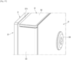
- an outer appearance of the front surface may be formed by the panel 31 viewed from the front. There may be no component exposed forward other than the panel 31 among components of the panel assembly 30, and thus the entire panel assembly 30 may be seen as formed by the panel 31.
- the front appearance of the refrigerator 1 or a home appliance may be formed by color of the panel 31 or color glowing on the panel 31.
- the upper bracket 34 may be mounted on the upper end of the member 32.
- a side surface of the upper bracket 34 may be accommodated on the upper end of the front part 321 and the upper end of the side part 322.
- the upper surface of the upper bracket 34 may be formed with a height corresponding to the upper end protrusion 321b.
- the upper surface of the upper bracket 34 may form an upper surface of the panel assembly 30 with the upper end protrusion 321b. Viewed from the front, the upper bracket 34 may not be exposed to the outside by being hidden by the panel 31 and the upper end protrusion 321b.
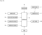
- the operation of the lighting device 36 may be performed by manipulation of a manipulator 14 of a user.
- the manipulator 14 may be disposed at one side of the refrigerator 1, and for example, may be disposed at one side of the cabinet 10. Needless to say, as necessary, the manipulator 14 may be included in the door 20 or manipulation may be input by touching and manipulating the panel 31. That is, the user may directly manipulate the manipulator 14 to set an operation of the lighting device 36 and may turn on or off the lighting device 36.
- the communicator 17 may communicate with the remote device 2 using various methods.
- the communicator 17 may have a communicable structure using at least one method such as wired, wireless, or short distance communication (Bluetooth, Wi-Fi, Zigbee, and NFC).
- the remote device 2 may be various devices that are capable of communicating, such as a dedicated terminal, a mobile phone, a tablet, a portable PC, a desktop PC, a remote control, or a Bluetooth speaker.
- the sensors 15 may be disposed at various positions for detecting proximity of the user, such as one side of the cabinet or one side of the door 20, and may be disposed at various positions for detecting proximity of the user. A plurality of sensors may be disposed at different positions.
- the lighting device 36 may be turned off or the brightness may be gradually dimmed to prevent glare of the user.
- the lighting device 35 may be turned on again or may return to an original brightness.
- the controller 13 may adjust a set temperature inside the refrigerator, and may operate the lighting device 36 to change color of the front surface of the door 20 to color corresponding to the corresponding temperature.
- the lighting device 36 may also be controlled to change the front color of the door 20 in response to play of music, and the front surface of the refrigerator the door 20 may be continuously changed in color with an equalizer while interacting with the played music.
- the lighting device 36 may be positioned below the upper end of the lower bracket 35. Thus, viewed from the front, the lighting device 36 may be prevented from being exposed, and a lighting spot (a hot spot) may be prevented from being formed adjacent to the light source 362, thereby improving the quality of a front appearance of the door 20 and preventing glare of the user.
- the front surface of the door 20 may glow brightly.
- a difference in light transmittance between a portion of the panel 31, which is not coated with the sealant 313, and a portion coated with the sealant 313 may not be recognized by a user.
- the sealant 313 may maintain a transparent or opaque state in the state in which the panel 31 and the member 32 are adhered.
- the sealant 313 may be spread thinly between the panel 31 and the member 32. Due to this spreadability, the sealant 313 may transmit light guided through the light guide plate 33.
- the lighting device 36 when the lighting device 36 is turned on, light may also be transmitted through the portion coated with the sealant 313, and the front surface of the door 20 may be implemented with set color.
- left and right ends of the light guide plate 33 may be fixed to the side parts 322 at both left and right side surfaces of the member 32.
- the left and right both ends of the light guide plate 33 may be slidably inserted into the light guide plate insertion space 324 to constrain the light guide plate 33.
- the front surface of the light guide plate 33 may be in close contact with the rear surface of the front part 321.
- the lighting device 36 In the state in which the lighting device 36 and the right supporter 37 are mounted inside the lower bracket 35, the lighting device 36 may be positioned at a set position, and the light source 362 may be positioned to face the lower end of the light guide plate 33. [(c) of FIG. 45 ]
- the back cover 39 may be mounted.
- the back cover 39 may be in contact with the upper bracket 34, the lower bracket 35, and the side parts 322 at both left and right sides of the member 32 and may define the rear surface of the panel assembly 30. [(e) of FIG. 45 ]
- the screw 399 may be coupled to fixedly mount the back cover 39.
- the screw 399 may be coupled along the upper bracket 34 and the lower bracket 35 to constrain the upper end of the back cover 39 and the lower end of the back cover 39. [(f) of FIG. 45 ]
- the panel 31 may be finally mounted on the front surface of the member 32, that is, the front part 321.
- the panel 31 may be supported by the front part 321 and a portion of a front surface of the lower bracket 35.
- the panel 31 may have a rear surface adhered to the member 32 and the lower bracket 35 in such a way that an entire front surface of the panel 31 is exposed.
- the sealant 313 may be formed of a transparent or translucent material, and thus light reflected forward from the light guide plate 33 may pass through the sealant 313 to illuminate the end of the panel 31.
- the panel assembly 30 When the panel 31 is completely adhered, the panel assembly 30 may be completely assembled. Since the panel 31 is mounted at a final stage of an assembly process, the panel 31 with a high weight may be easily managed. Since movement and processing of the panel 31 may be minimized, the panel 31 may also be prevented from being damaged. Handling of other components under assembly may be easily performed by assembling the panel 31 last. [(g) of FIG. 45 ]
- the front color of the door 20 may be seen as color of the panel 31, and the texture and pattern formed on the panel 31 may be seen.
- the color of the panel 31 may be color with a brightness greater than 0 and may be formed in a color other than black.
- the color of the front surface of the door 20 in the state in which the lighting device 36 is turned may also be referred to as a first color.
- the lighting device 36 may be turned on, and when the lighting device 36 is turned on, the front surface of the door 20 may glow with color set by the controller 13.
- Some of the plurality of doors 20 forming the front appearance of the refrigerator 1 may emit light or the plurality of doors 20 may independently emit light to form the front appearance of the refrigerator 1 with set color.
- the refrigerator 1 may be operated to cause some doors 20 of a plurality of doors to glow or glow with specific color. That is, all the lighting devices 36 included in the doors 20 may not be operated, but instead, only some of all the doors 20 may glow.
- any one door 201a of the refrigerating compartment door 201 may glow. That is, the left refrigerating compartment door 201a among the left refrigerating compartment door 201a and the right refrigerating compartment door 201b may glow. Needless to say, any one of the freezing compartment doors 202 may glow.
- the lighting device 36 included in the panel assembly 30 may be controlled by the controller 13 according to the aforementioned various conditions.
- the controller 13 may control the lighting device 36 to cause one pair of the refrigerating compartment doors 201 to be seen with the first color.
- the controller 13 may control the lighting device 36 to cause one pair of the refrigerating compartment doors 201 to be seen with the second color.
- the refrigerating compartment door 201 and the freezing compartment door 202 may be distinguished therebetween with colors, and according to a temperature change inside the refrigerator, the colors of the refrigerating compartment door 201 and the freezing compartment door 202 may also be changed.
- the user may intuitively recognize an operation state of each storage space as well as may distinguish between the refrigeration compartment and the freezing compartment.
- the member 32 may be formed by injection, but in the case of injection molding, the structure of the mold becomes complicated due to the shape of the side part 322 of the right and left side ends of the member 32, and thus productivity may be degraded.
- the extrusion molding device 3 for molding the member 32 may include a material feeding device 301, a primary mold 302a, a secondary mold 302b, a tertiary mold 303, a cooling device 304, and a cutting device 306.
- a material for molding the member 32 may be fed to the material feeding device 301.
- the used material may be, for example, a transparent ABS material.
- the material feeding device 301 may include a screw 301a for moving the fed material, and a heater 301b for heating the material, and may continuously feed the material toward a mold after melting the material.
- the secondary mold 302b may be placed consecutively with the primary mold 302a.
- the material uniformly distributed and fed through the primary mold 302a may be injected into the secondary mold 302b and may primarily form an overall shape of the outer appearance of the member 32 while passing through the secondary mold 302b.
- the primary mold 302a and the secondary mold 302b may be in contact with each other, and the material passing through the primary mold 302a may be input to the secondary mold 302b to pass through the secondary mold 302b. Needless to say, as necessary, the primary mold 302a and the secondary mold 302b may also be formed as a single mold 302. [S200]
- the material passing through the secondary mold 302b may pass through the tertiary mold 303 after being molded to have a similar basic shape and size to the member 32.
- the shape of the inside of the tertiary mold 303 may be close to the size and shape of the member 32 compared with the secondary mold 302b.
- a dimension of the material molded while passing through the tertiary mold 303 may be corrected and may be almost similar to a dimension of the member 32.
- the tertiary mold 303 may be configured in a plural number, and a dimension of the material may be more precisely corrected while the material passes through the plurality of tertiary molds 303.
- only one secondary mold 302b may be provided or two or more secondary molds 302b may be provided.
- the material molded while passing through the tertiary mold 303 may be cooled while passing through the cooling device 304.
- the inside of the cooling device 304 may be filled with cooling water W and may be in a vacuum state.
- a plurality of cooling molds 305 may be further provided inside the cooling device 304.
- the plurality of cooling molds 305 may be provided inside the cooling device 304.
- the plurality of cooling molds 305 may be arranged along a moving direction of the extruded material 320.
- the cooling mold 305 may partition the inside of the cooling device 304, and the water inlet 304a and the water outlet 304b may be connected to the cooling mold 305 to inject and discharge the cooling water W to and from each partitioned space.
- the extruded material 320 moving along the cooling device 304 may sequentially pass through the plurality of cooling molds 305.
- a dimension of the extruded material 320 may be precisely corrected again while the extruded material 320 passes through the cooling molds 305, and when the extruded material 320 passes through the lastly placed cooling mold 305 among the plurality of cooling molds 305, the extruded material 320 may be molded with the same dimension as the dimension of the last member 32.
- the opening may be formed to correspond to the dimension and shape of the member 32. That is, the opening may include a front part opening 305a forming the front part 321, and a first part opening 305b, a second part opening 305c, and a third part opening 305d that form a first part 322a, the third part 322b, and the second part 323 of the side part 322.
- the extruded material 320 may have the same cross-sectional shape as the member 32.
- the extruded material 320 passing through the cooling device 304 may have the same cross-sectional shape as the member 32, and the extruded material 320 may be cooled while passing through the cooling device 304 and the shape of the extruded material 320 may be completed actually.
- the extruded material 320 passing through the cooling device 304 may be cut to a length corresponding to one member 32 by the cutting device 306.
- the member 32 may be continuously molded.
- a cut surface cut by the cutting device 306 may be further processed or a part of the upper and lower ends of the side part 322 may be further cut.
- the panel assembly may be shield an open front surface of the door body.
- Another embodiment of the present disclosure may have the same structure as the aforementioned embodiment except for some components of the door body, and thus the same components as in the aforementioned embodiment use the same reference numeral, and a detailed description thereof may be omitted.
- FIG. 43 is an exploded perspective view of a refrigerator door according to another embodiment of the present disclosure.
- the overall structure of the panel assembly 30 may be the same as the aforementioned embodiment. That is, the panel assembly 30 may include the panel 31, the member 32, the light guide plate 33, the upper bracket 34, the lower bracket 35, the lighting device 36, the right supporter 37, and the back cover 39, which are the same as those of the aforementioned embodiment, and thus a detailed description thereof will be omitted and may refer to the drawings of the aforementioned embodiments.
- the door body 40' may include the door liner 42 forming a bottom surface of the door 20, the upper cap deco 43 disposed on upper and lower ends of the door liner 42, and the side deco 44 disposed on right and left side ends of the door liner 42.
- the upper cap deco 43 and the lower cap deco 45 may form upper and lower surfaces of the door 20, and the side deco 44 may form right and left side surfaces of the door 20.
- the panel assembly 30 may be coupled to the upper cap deco 43, the lower cap deco 45, and a front end of the side deco 44, and a space in which an insulator is filled may be formed with the door liner 42 inside the door 20.
- a bottom surface of the panel assembly 30, i.e., a rear surface of the back cover 39 may be in contact with the insulator.
- the insulator may not penetrate into a space inside the panel assembly 30 and may be protected by the back cover 39.
- the rear surface of the back cover 39 may be in contact with the insulator, and the panel assembly 30 may be firmly fixed to the door 20.
- the storage space may be partitioned into right and left sides, and the door includes a refrigerating compartment door and a freezing compartment door at right and left sides.
- Another embodiment of the present disclosure may have the same structure as the aforementioned embodiment except for arrangement of a storage space and a door, and thus the same components as in the aforementioned embodiment use the same reference numeral, and a detailed description thereof may be omitted.
- the door 20 may include a freezing compartment door 203 for opening and closing the freezing compartment and a refrigerating compartment door 204 for opening and closing the refrigerating compartment.
- the freezing compartment door 203 and the refrigerating compartment door 204 may be arranged in parallel to each other at right and left sides, and the refrigerating compartment and the freezing compartment may be configured to be opened and closed via rotation.
- a panel assembly forming the exterior may be applied to other home appliances other than a refrigerator to change color of an outer appearance of the home appliance.
- Another embodiment of the present disclosure may have the same structure as the aforementioned embodiment except for the size and shape of a panel and an application target of the panel, and thus the same components as in the aforementioned embodiment use the same reference numeral, and a detailed description thereof may be omitted.
- the case border 512 may include one pair of side borders 512a forming both side surfaces, an upper border 512b for connecting upper ends of the pair of side borders 512a, and a lower border 512c for connecting lower ends of the pair of side borders 512a.
- the panel assembly 52 may have the same structure as the panel assembly 30 according to the aforementioned embodiment, and thus the front surface of the panel assembly 52 may glow with various colors under control of the controller 13.
- the entire panel 521 may glow due to light emitted from the lighting device 36, and the front appearance of the indoor unit 5 may be formed by color corresponding to the color of the light emitted from the lighting device 36.
- An operation of the lighting device 36 may be controlled according to control of the controller 13.
- the panel 521 may glow with various colors, and thus the front appearance of the indoor unit 5 may also correspond to various colors.
- FIG. 59 is a perspective view of a clothing manager according to another embodiment of the present disclosure.
- FIG. 60 is an exploded perspective view of a door of the clothing manager.
- an outer appearance of a clothing manager 6 may be formed by a case 61 forming a clothing accommodation space, and a door 62 for opening and closing an open front surface of the case 61.
- a discharge port for discharging steam generated from the steam generator and dried air heated by the heat pump, and an absorption port for absorbing air from the clothing accommodation space may be formed inside the clothing accommodation space.
- the door 62 may be rotatably mounted on the case 61, and in the state in which the door 62 is closed, the door 62 may form a front appearance of the clothing manager 6.
- the door 62 may include a door body 63 for opening and closing the clothing accommodation space, and a panel assembly 64 mounted on the door body 63 to form a front surface of the door 62.
- the side deco 632, the upper cap deco 633, and the lower cap deco 634 may protrude compared with the front surface of the body plate 631, and a panel accommodation space 631a in which the panel assembly 64 is accommodated may be formed in front of the body plate 631.
- the panel assembly 64 may have the same structure as the panel assembly 30 according to the aforementioned embodiment, and thus the front surface of the panel assembly 64 may glow with various colors under control of the controller 13.
- the entire panel 541 may glow due to light emitted from the lighting device 36, and the front appearance of the clothing manager 6 may be formed by color corresponding to the color of the light emitted from the lighting device 36.
- outer color of the front surface of the clothing manager 6 may be freely changed under control of the lighting device 36 in the state in which the panel assembly 64 is maintained to be assembled and mounted without replacement of the panel assembly 64.
- the outer appearance of the clothing manager 6 may be changed according to surrounding furniture or environments, and according to an operation state of the clothing manager 6, the operation state may be intuitively represented by changing the outer appearance of the clothing manager 6.
- FIG. 61 is a perspective view of a washer according to another embodiment of the present disclosure.
- FIG. 62 is an exploded perspective view of a dissembled panel assembly of the washer.
- a washer 7 may include a case 71 forming an outer shape, and a panel assembly 73 mounted on a front surface of the case 71 to form a front appearance of the washer 7.
- the case border 72 may include one pair of side borders 721 forming both side surfaces, an upper border 722 for connecting upper ends of the pair of side borders 721, and a lower border 723 for connecting lower ends of the pair of side borders 721.
- the panel assembly 73 may include a panel 731 forming a front surface, a member 732 on which the panel 731 is mounted, an upper bracket 733 mounted on an upper end of the member 732 to form an upper surface of the panel assembly 73, and a lower bracket 734 mounted on a lower end of the member 732 to form a lower surface of the panel assembly 73.
- the entire panel 731 may glow due to light emitted from the lighting device 36, and the front appearance of the washer 7 may be formed by color corresponding to the color of the light emitted from the lighting device 36.
- An operation of the lighting device 36 may be controlled according to control of the controller 13.
- the panel 731 may glow with various colors, and thus the front appearance of the washer 7 may also correspond to various colors.
- a drier having the same structure of the outer appearance of the washer 7 may also have the same structure of the panel assembly thereof.
- a structure configured by the drier and the washer are vertically stacked and a structure configured by disposing the drier and the washer in one case may also have the same panel assembly.
- an outer appearance of a dish washer 8 may be formed by a case 81 forming a space for accommodating and washing dishes, and a door 82 for opening and closing an open front surface of the case 81.
- a lower end of the door 82 may be rotatably mounted on the case 81, and in the state in which the door 82 is closed, the door 82 may form the front appearance of a dish washer 8.
- the door 82 may include a door body 83 for opening and closing the washing space, and a panel assembly 84 mounted on the door body 83 to form a front surface of the door 82.
- a body plate 831 may be provided on a front surface of the door body 83 to form a front surface of the door body 83.
- a side deco 832 extending in a vertical direction may be provided along right and left side ends of the door body 83, and right and left side surfaces of the door body 83 may be formed by the side deco 832.
- An upper cap deco 833 for connecting upper ends of the side deco 832 at right and left sides, and a lower cap deco 834 for connecting lower ends of the side deco 832 at right and left sides may be provided.
- a lower end of the panel assembly 84 may be inserted into the lower cap deco 834, and an upper end of the panel assembly 84 may be coupled to the upper cap deco 833 to be fixedly mounted inside the panel accommodation space 831a.
- a perimeter of the panel assembly 84 may be supported by the side deco 832, the upper cap deco 833, and the lower cap deco 834.
- the panel assembly 84 may include a panel 841 forming a front surface thereof, a member 842 on which the panel 841 is mounted, an upper bracket 843 mounted on an upper end of the member 842 to form an upper surface of the panel assembly 84, and a lower bracket 844 mounted on a lower end of the member 842 to form a lower surface of the panel assembly 84.
- the entire panel 841 may glow due to light emitted from the lighting device 36, and the front appearance of the dish washer 8 may be formed by color corresponding to the color of the light emitted from the lighting device 36.
- a manipulator for manipulating an operation of the cooking device 9 may be formed above the door body 93.
- the manipulator may include a display 936, and a knob 936 or a button for manipulation.
- a sight window 935 for seeing the cooking space therethrough may be formed almost at the center of the door body 93.
- Components of the panel assembly 94 may have the same structure as the panel assembly 30 according to the aforementioned embodiment except for the panel openings 945, 946, and 947, and thus the front surface of the panel assembly 94 may glow with various colors under control of the controller 13.
- the panel assembly 94 may include a panel 941 forming a front surface thereof, a member 942 on which the panel 941 is mounted, an upper bracket 943 mounted on an upper end of the member 942 to form an upper surface of the panel assembly 94, and a lower bracket 944 mounted on a lower end of the member 942 to form a lower surface of the panel assembly 94.
- a handle 95 for manipulation to open and close the door 92 may be further provided on a front surface of the panel assembly 94.
- Outer appearances of the refrigerator according to the embodiments of the present disclosure may be formed by a panel assembly forming a front appearance.
- color of the panel assembly itself may be represented to the outside, and the refrigerator and the home appliance may have an outer appearance with a first color.
- the panel assembly may have an outer appearance with a second color by changing the color of the panel assembly by the lighting device.
- the outer appearance of the refrigerator in particular, color thereof may be freely changed without replacement of panel assembly, and dramatic improvement in the outer appearance of the refrigerator may be expected.
- the lighting device may emit light with various colors, and thus outer color of the refrigerator and the home appliance may be advantageously changed.
- a panel forming an outer appearance of a front surface of the panel assembly may be simply adhered to a member via an adhesive member, and thus an outer appearance of the entire door as well as an outer appearance of the panel assembly may be formed by a front plate without exposure of a separate fixing structure to expect improvement in an entire outer appearance of the refrigerator and the home appliance.
- the member may include a front part to which the panel is to be adhered, and a perimeter of the panel may be adhered to the front part of the member via an adhesive member.
- the adhesive member may be formed of a material for transmitting light therethrough, and thus, light may also be transmitted in a region of the panel, in which the adhesive member is disposed, to cause the entire panel to glow.
- a pattern part having patterns with higher density may be further formed on a portion of the light guide plate, which corresponds to a position of the adhesive member.
- light may be more concentrated on a portion in which the adhesive member is disposed, and thus even if the panel is adhered by an adhesive member, the entire front surface of the panel may glow with uniform brightness without shadow on the panel.
- An edge reflector with higher reflectance may be formed on a portion of a reflective sheet, which corresponds to a position of the adhesive member.
- light may be more concentrated on a portion in which the adhesive member is disposed, and thus even if the panel is adhered by an adhesive member, the entire front surface of the panel may glow with uniform brightness without shadow on the panel.
- side parts may be formed on both side surfaces of the member, and the light guide plate may be slidably inserted through the side part.
- the light guide plate In the state in which the light guide plate is slidably inserted along the side part, the light guide plate may be in contact with a front part of the member.
- the member may be formed of a material for transmitting light therethrough to simultaneously support the member and the light guide plate.
- the light guide plate may be maintained to be spaced apart from the panel by a constant interval, and thus the panel may glow with uniform brightness.
- the light guide plate may be maintained to be in contact with the front part of the member, thereby preventing a dark part such as stain from being formed on the panel.
- a second space into which an upper bracket and a lower bracket are inserted may be further formed on the side part, and thus the upper bracket and the lower bracket may be simply assembled and mounted, thereby improving assembly workability.
- the upper bracket, the lower bracket, and the light guide plate may be decoupled without a separate coupling and dissembling operation, thereby advantageously improving serviceability.
- the member may be integrally formed with the front part, and a structure for mounting the panel and the light guide plate may be advantageously provided by simply molding the member.
- the member may be formed with the same or similar cross-sectional shape in a vertical direction to be molded by extrusion, and thus the formability of the member and the productivity of the entire panel assembly may be advantageously improved.
- a light diffuser may be added to the member, light that is transmitted through the member and is directed toward the panel may be diffused to cause the panel to glow brightly, and accordingly, the entire surface of the panel may glow uniformly and brightly.
- the transparency of the member may be lowered in the state in which the lighting device is turned off to prevent components disposed behind the member from being exposed to the outside, thereby advantageously preventing an outer appearance from being adversely affected in the state in which the lighting device is turned off.
- the front plate and the support member may be adhered by the sealant and may be firmly fixed, thereby advantageously simplifying an assembly operation.
- a light guide plate disposed behind the panel may be fixed by a simple coupling structure of a member, an upper bracket, and a lower bracket. A component for fixing the light guide plate may be prevented being exposed to the front of the panel assembly.
- the both left and right ends of the light guide plate may be constrained by side parts of the member, and the upper and lower ends of the light guide plate may be constrained by the upper and lower brackets, and thus upper, lower, left, and right peripheries of the light guide plate may entirely fixed. Therefore, even if the door is repeatedly opened and closed, the light guide plate may be stably maintained at an initial mounting position, and the panel may glow with uniform brightness.
- the upper bracket and the lower bracket may have a simple coupling structure by being inserted into the upper and lower ends of the member, and the upper and lower ends of the light guide plate may also be advantageously supported through such a coupling structure.
Landscapes
- Engineering & Computer Science (AREA)
- Physics & Mathematics (AREA)
- General Engineering & Computer Science (AREA)
- Chemical & Material Sciences (AREA)
- Combustion & Propulsion (AREA)
- Mechanical Engineering (AREA)
- Thermal Sciences (AREA)
- General Physics & Mathematics (AREA)
- Optics & Photonics (AREA)
- Refrigerator Housings (AREA)
- Devices That Are Associated With Refrigeration Equipment (AREA)
Claims (12)
- Haushaltsgerät, das Folgendes enthält:ein Gehäuse (10), das einen Raum bildet, undeine Tür (20) zum Öffnen und Schließen des Raums, die konfiguriert ist, Licht abzustrahlen, wobei die Tür (20) einen Türkörper (40) und eine Tafelanordnung (30), die am Türkörper (40) montiert ist, umfasst,wobei die Tafelanordnung (30) Folgendes enthält:eine Beleuchtungsvorrichtung (36), die konfiguriert ist, Licht abzustrahlen;eine Tafel (31), die eine Frontoberfläche der Tür (20) bildet und konfiguriert ist, Licht durchzuleiten;eine Lichtführungsplatte (33), die hinter der Tafel (31) angeordnet ist und konfiguriert ist, Licht, das von der Beleuchtungsvorrichtung (36) abgestrahlt wird, zur Tafel (31) zu führen; undein Element (32), das zwischen der Tafel (31) und der Lichtführungsplatte (33) angeordnet ist und konfiguriert ist, Licht von der Lichtführungsplatte (33) zur Tafel (31) zu leiten;wobei das Element (32) Folgendes enthält: einen Frontteil (321), an dem die Tafel (31) montiert ist, und einen Seitenteil (322), der von Seiten, die dem Frontteil (321) gegenüberliegen, zum Türkörper (40) verläuft, um einen Raum zu bilden, in den die Lichtführungsplatte (33) eingesetzt ist; und/oderdie Tafelanordnung (30) ferner Folgendes enthält: einen oberen Haltebügel (34), der eine obere Oberfläche der Tafelanordnung (30) bildet, und einen unteren Haltebügel (35), der eine untere Oberfläche der Tafelanordnung (30) bildet, wobei der obere Haltebügel (34) und der untere Haltebügel (35) bei oberen bzw. unteren Enden des Elements (32) montiert sind und ein oberes Ende und/oder ein unteres Ende des Elements (32) abgestuft sind, um den entsprechenden des oberen Haltebügels (34) und des unteren Haltebügels (35) daran aufzunehmen.
- Haushaltsgerät nach Anspruch 1, wobei der Seitenteil (322) einen ersten Teil (322a), der zum Türkörper (40) verläuft, und einen zweiten Teil (323), der vom ersten Teil (322a) parallel zum Frontteil (321) verläuft, um einen ersten Raum (324) zu bilden, in den die Lichtführungsplatte (33) eingesetzt ist, enthält.
- Haushaltsgerät nach Anspruch 2, wobeider erste Raum (324) eine offene obere und eine offene untere Oberfläche aufweist, durch die die Lichtführungsplatte (33) in vertikaler Richtung einsetzbar und entnehmbar ist, und/oderhorizontale Querschnitte des Elements (32) durch verschiedene Punkte in vertikaler Richtung dieselbe Form aufweisen.
- Haushaltsgerät nach Anspruch 2 oder 3, wobei der Frontteil (321) und jeder der zweiten Teile (323) um eine Entfernung voneinander beabstandet sind, die einer Dicke der Lichtführungsplatte (33) entspricht.
- Haushaltsgerät nach Anspruch 2, 3 oder 4, wobei der Frontteil (321) mit einer Frontoberfläche der Lichtführungsplatte (33), die in den ersten Raum (324) eingesetzt ist, in Kontakt ist und der zweite Teil (323) mit einer Rückoberfläche der Lichtführungsplatte (33), die in den ersten Raum (324) eingesetzt ist, in Kontakt ist und/oder der erste Teil (322a) mit einer Seitenoberfläche der Lichtführungsplatte (33), die in den ersten Raum (324) eingesetzt ist, in Kontakt ist.
- Haushaltsgerät nach einem der Ansprüche 2 bis 5, das ferner Folgendes umfasst:dritte Teile (322b), die von den ersten Teilen (322a) parallel zu den zweiten Teilen (323) vorstehen und von ihnen beabstandet sind, um einen zweiten Raum (325) dazwischen zu bilden,wobei der obere Haltebügel (34) und der untere Haltebügel (35) in den zweiten Raum (325) eingesetzt sind, der durch die ersten Teile (322a), die zweiten Teile (323) und die dritten Teile (322b) gebildet ist.
- Haushaltsgerät nach Anspruch 6, wobei jeder der dritten Teile (322b) im Vergleich zum entsprechenden zweiten Teil (323) weiter zum Zentrum des Elements (32) vorsteht.
- Haushaltsgerät nach einem der vorhergehenden Ansprüche, wobei die Beleuchtungsvorrichtung (36) an mindestens einem des oberen Haltebügels (34) und des unteren Haltebügels (35) montiert ist.
- Haushaltsgerät nach einem der vorhergehenden Ansprüche, wobeidie Tafelanordnung (30) ferner eine rückwärtige Abdeckung (39) enthält, die eine Rückoberfläche der Tafelanordnung (30) bildet; unddie rückwärtige Abdeckung an einer Rückoberfläche des Seitenteils (322) montiert ist.
- Haushaltsgerät nach einem der vorhergehenden Ansprüche, wobei
die Tafel (31) und das Element (32) dieselbe Breite und/oder dieselbe Höhe und/oder denselben Flächeninhalt aufweisen. - Haushaltsgerät nach einem der vorhergehenden Ansprüche, wobei ein Lichtdiffusor zum Element (32) hinzugefügt ist, um Licht, das durch das Element (32) geleitet wird und zur Tafel (31) gerichtet ist, zu streuen.
- Haushaltsgerät nach einem der vorhergehenden Ansprüche, wobei das Haushaltsgerät eine Kühlvorrichtung, ein Geschirrspüler, eine Waschmaschine, ein Kleidungsmanager, eine Wasch- und/oder Trockenmaschine, eine Kochvorrichtung oder ein Ofen ist.
Priority Applications (1)
| Application Number | Priority Date | Filing Date | Title |
|---|---|---|---|
| EP25170110.8A EP4579161A3 (de) | 2021-07-13 | 2022-07-13 | Haushaltsgerät |
Applications Claiming Priority (3)
| Application Number | Priority Date | Filing Date | Title |
|---|---|---|---|
| KR1020210091835A KR20230011154A (ko) | 2021-07-13 | 2021-07-13 | 냉장고 및 가전기기 |
| KR1020210091832A KR20230011153A (ko) | 2021-07-13 | 2021-07-13 | 냉장고 및 가전기기 |
| KR1020210091825A KR20230011147A (ko) | 2021-07-13 | 2021-07-13 | 냉장고 및 가전기기 |
Related Child Applications (1)
| Application Number | Title | Priority Date | Filing Date |
|---|---|---|---|
| EP25170110.8A Division EP4579161A3 (de) | 2021-07-13 | 2022-07-13 | Haushaltsgerät |
Publications (2)
| Publication Number | Publication Date |
|---|---|
| EP4119873A1 EP4119873A1 (de) | 2023-01-18 |
| EP4119873B1 true EP4119873B1 (de) | 2025-04-16 |
Family
ID=82594574
Family Applications (2)
| Application Number | Title | Priority Date | Filing Date |
|---|---|---|---|
| EP25170110.8A Pending EP4579161A3 (de) | 2021-07-13 | 2022-07-13 | Haushaltsgerät |
| EP22184627.2A Active EP4119873B1 (de) | 2021-07-13 | 2022-07-13 | Haushaltsgerät |
Family Applications Before (1)
| Application Number | Title | Priority Date | Filing Date |
|---|---|---|---|
| EP25170110.8A Pending EP4579161A3 (de) | 2021-07-13 | 2022-07-13 | Haushaltsgerät |
Country Status (4)
| Country | Link |
|---|---|
| US (2) | US12235036B2 (de) |
| EP (2) | EP4579161A3 (de) |
| CN (1) | CN115615115A (de) |
| AU (2) | AU2022205217B2 (de) |
Families Citing this family (6)
| Publication number | Priority date | Publication date | Assignee | Title |
|---|---|---|---|---|
| KR20230071579A (ko) * | 2021-11-16 | 2023-05-23 | 엘지전자 주식회사 | 가전 기기 |
| KR20230071624A (ko) * | 2021-11-16 | 2023-05-23 | 엘지전자 주식회사 | 가전 기기 |
| KR20230071580A (ko) * | 2021-11-16 | 2023-05-23 | 엘지전자 주식회사 | 가전 기기 |
| KR20230075701A (ko) * | 2021-11-23 | 2023-05-31 | 엘지전자 주식회사 | 가전 기기 |
| KR102900195B1 (ko) * | 2022-06-27 | 2025-12-15 | 엘지전자 주식회사 | 도어 업그레이드 키트 및 이를 포함하는 냉장고 |
| KR20240002821A (ko) * | 2022-06-30 | 2024-01-08 | 엘지전자 주식회사 | 냉장고 |
Citations (2)
| Publication number | Priority date | Publication date | Assignee | Title |
|---|---|---|---|---|
| US20100295425A1 (en) * | 2009-05-22 | 2010-11-25 | Lg Electronics Inc. | Decorative panel and refrigerator having the same |
| US20100313592A1 (en) * | 2008-02-21 | 2010-12-16 | Lg Electronics Inc. | Refrigerator and door thereof |
Family Cites Families (48)
| Publication number | Priority date | Publication date | Assignee | Title |
|---|---|---|---|---|
| US6059420A (en) * | 1999-02-17 | 2000-05-09 | Rogers; Thomas | See through refrigerator door construction |
| DE102005021607A1 (de) | 2005-05-10 | 2006-11-23 | BSH Bosch und Siemens Hausgeräte GmbH | Tür für ein Haushaltsgerät |
| KR101576672B1 (ko) * | 2008-02-21 | 2015-12-10 | 엘지전자 주식회사 | 냉장고 및 냉장고 도어 |
| KR101291798B1 (ko) * | 2008-06-10 | 2013-07-31 | 엘지디스플레이 주식회사 | 액정표시모듈 및 그 조립방법 |
| WO2011093614A2 (en) * | 2010-02-01 | 2011-08-04 | Lg Electronics Inc. | Refrigerator and method for controlling the same |
| KR101713333B1 (ko) * | 2010-09-01 | 2017-03-07 | 엘지전자 주식회사 | 냉장고 도어 |
| KR101843337B1 (ko) * | 2010-10-28 | 2018-03-30 | 삼성전자주식회사 | 디스플레이 모듈 및 디스플레이 시스템 |
| TR201010199A2 (tr) | 2010-12-08 | 2012-06-21 | Bsh Ev Aletleri̇ San. Ve Ti̇c. A.Ş. | Işiklandırılmış kapıya sahip bir soğutucu cihaz |
| US9052536B2 (en) * | 2011-05-10 | 2015-06-09 | Anthony, Inc. | Display case door with transparent LCD panel |
| FR2978525B1 (fr) * | 2011-07-29 | 2018-05-18 | Saint-Gobain Glass France | Vitrage multiple lumineux de meuble |
| WO2013051473A1 (ja) * | 2011-10-06 | 2013-04-11 | シャープ株式会社 | 照明装置、表示装置、及びテレビ受信装置 |
| ES2533244B1 (es) * | 2013-10-03 | 2016-01-22 | Bsh Electrodomésticos España, S.A. | Aparato doméstico |
| JP6244195B2 (ja) * | 2013-12-19 | 2017-12-06 | 日立アプライアンス株式会社 | 冷蔵庫 |
| JP2015203525A (ja) * | 2014-04-14 | 2015-11-16 | 株式会社東芝 | 冷蔵庫 |
| FR3021093B1 (fr) * | 2014-05-13 | 2020-07-17 | Saint-Gobain Glass France | Ensemble vitre lumineux, porte et meuble refrigere avec cet ensemble et fabrication. |
| KR20160044721A (ko) * | 2014-10-16 | 2016-04-26 | 삼성전자주식회사 | 냉장고 |
| JP2017106637A (ja) * | 2014-12-26 | 2017-06-15 | 三星電子株式会社Samsung Electronics Co.,Ltd. | 冷蔵庫および照明装置 |
| KR101892794B1 (ko) * | 2015-08-25 | 2018-08-28 | 엘지전자 주식회사 | 냉장고 |
| CN107014145A (zh) * | 2016-01-27 | 2017-08-04 | 凌晖科技股份有限公司 | 电器的门板装置 |
| CN105627676A (zh) * | 2016-03-01 | 2016-06-01 | 上海九山电子科技有限公司 | 自带半透明液晶发光结构的冷柜门及其制造方法 |
| KR20170106575A (ko) * | 2016-03-11 | 2017-09-21 | 삼성전자주식회사 | 광원 모듈 및 이를 포함하는 조명 장치 |
| KR102661024B1 (ko) * | 2016-08-23 | 2024-04-26 | 주식회사 위니아 | 냉장고 도어 |
| KR102687627B1 (ko) * | 2016-08-29 | 2024-07-23 | 엘지전자 주식회사 | 냉장고 |
| KR102627962B1 (ko) * | 2016-12-12 | 2024-01-23 | 엘지전자 주식회사 | 냉장고 |
| KR102273092B1 (ko) * | 2016-12-12 | 2021-07-06 | 엘지전자 주식회사 | 냉장고 |
| JP6868401B2 (ja) * | 2017-01-18 | 2021-05-12 | 東芝ライフスタイル株式会社 | 冷蔵庫 |
| KR102733673B1 (ko) * | 2017-01-23 | 2024-11-26 | 엘지전자 주식회사 | 냉장고 및 냉장고용 패널 어셈블리 |
| KR102259753B1 (ko) * | 2017-03-24 | 2021-06-02 | 엘지전자 주식회사 | 냉장고 |
| KR102423822B1 (ko) * | 2017-04-25 | 2022-07-21 | 엘지전자 주식회사 | 냉장고 |
| CN108931100A (zh) * | 2017-05-26 | 2018-12-04 | 东芝生活电器株式会社 | 冰箱 |
| US10810914B2 (en) * | 2017-08-09 | 2020-10-20 | True Manufacturing Co., Inc. | Illuminating display window and merchandiser display unit comprising same |
| KR102499468B1 (ko) * | 2018-02-12 | 2023-02-15 | 엘지전자 주식회사 | 냉장고 |
| WO2019175978A1 (ja) * | 2018-03-13 | 2019-09-19 | 三菱電機株式会社 | 冷蔵庫及びその冷蔵庫の製造方法 |
| EP3575715B1 (de) * | 2018-05-28 | 2025-06-25 | LG Electronics Inc. | Kühlschrank |
| KR102126864B1 (ko) * | 2018-06-01 | 2020-06-25 | 엘지전자 주식회사 | 냉장고 |
| KR102071659B1 (ko) * | 2018-06-01 | 2020-03-11 | 엘지전자 주식회사 | 냉장고 |
| KR102096957B1 (ko) * | 2018-06-01 | 2020-04-03 | 엘지전자 주식회사 | 냉장고 및 이의 제어방법 |
| KR102187339B1 (ko) * | 2018-06-01 | 2020-12-07 | 엘지전자 주식회사 | 냉장고 |
| DE102018005481B4 (de) * | 2018-07-11 | 2023-03-09 | Emz-Hanauer Gmbh & Co. Kgaa | Haushalts-Kühlgerät mit Bodenbaugruppe und daran angebrachter Leuchtleiste |
| KR102149201B1 (ko) * | 2018-07-13 | 2020-08-28 | 엘지전자 주식회사 | 냉장고 및 냉장고의 제어 방법 |
| WO2020096258A1 (ko) * | 2018-11-08 | 2020-05-14 | 엘지전자 주식회사 | 패널 어셈블리, 냉장고 및 가전제품 |
| CN112797711A (zh) * | 2019-11-13 | 2021-05-14 | Lg电子株式会社 | 冰箱 |
| US12442584B2 (en) * | 2019-12-05 | 2025-10-14 | Lg Electronics Inc. | Refrigerator |
| DE102020109934A1 (de) * | 2020-02-19 | 2021-08-19 | Liebherr-Hausgeräte Ochsenhausen GmbH | Kühl- und/oder Gefriergerät mit Außenbeleuchtungskonzept |
| ES2961137T3 (es) * | 2020-02-21 | 2024-03-08 | Liebherr Hausgeraete Ochsenhausen Gmbh | Frigorífico y/o congelador con iluminación especial del espacio interior |
| KR20210130419A (ko) * | 2020-04-22 | 2021-11-01 | 삼성전자주식회사 | 냉장고 |
| KR20220005218A (ko) * | 2020-07-06 | 2022-01-13 | 엘지전자 주식회사 | 냉장고 |
| KR20220146241A (ko) * | 2021-04-23 | 2022-11-01 | 엘지전자 주식회사 | 냉장고 |
-
2022
- 2022-07-13 EP EP25170110.8A patent/EP4579161A3/de active Pending
- 2022-07-13 EP EP22184627.2A patent/EP4119873B1/de active Active
- 2022-07-13 AU AU2022205217A patent/AU2022205217B2/en active Active
- 2022-07-13 US US17/863,821 patent/US12235036B2/en active Active
- 2022-07-13 CN CN202210826267.0A patent/CN115615115A/zh active Pending
-
2024
- 2024-08-29 AU AU2024216423A patent/AU2024216423A1/en active Pending
-
2025
- 2025-01-23 US US19/035,019 patent/US20250164179A1/en active Pending
Patent Citations (2)
| Publication number | Priority date | Publication date | Assignee | Title |
|---|---|---|---|---|
| US20100313592A1 (en) * | 2008-02-21 | 2010-12-16 | Lg Electronics Inc. | Refrigerator and door thereof |
| US20100295425A1 (en) * | 2009-05-22 | 2010-11-25 | Lg Electronics Inc. | Decorative panel and refrigerator having the same |
Also Published As
| Publication number | Publication date |
|---|---|
| EP4579161A3 (de) | 2025-08-27 |
| AU2024216423A1 (en) | 2024-09-19 |
| US12235036B2 (en) | 2025-02-25 |
| EP4119873A1 (de) | 2023-01-18 |
| US20250164179A1 (en) | 2025-05-22 |
| CN115615115A (zh) | 2023-01-17 |
| AU2022205217B2 (en) | 2024-05-30 |
| EP4579161A2 (de) | 2025-07-02 |
| US20230018403A1 (en) | 2023-01-19 |
| AU2022205217A1 (en) | 2023-02-02 |
Similar Documents
| Publication | Publication Date | Title |
|---|---|---|
| EP4119873B1 (de) | Haushaltsgerät | |
| US20250164180A1 (en) | Refrigerator and home appliance | |
| US20260016220A1 (en) | Refrigerator | |
| EP4119871B1 (de) | Haushaltsgerät mit einer plattenanordnung | |
| US20250189208A1 (en) | Home appliance | |
| KR20230011153A (ko) | 냉장고 및 가전기기 | |
| US12529512B2 (en) | Refrigerator and home appliance | |
| KR20230011150A (ko) | 냉장고 및 가전기기 | |
| EP4549857A2 (de) | Haushaltsgerät | |
| KR20230011147A (ko) | 냉장고 및 가전기기 | |
| KR20230071625A (ko) | 가전 기기 | |
| KR20230011154A (ko) | 냉장고 및 가전기기 | |
| KR20230011148A (ko) | 냉장고 및 가전기기 | |
| KR20230173566A (ko) | 냉장고 | |
| KR20230075701A (ko) | 가전 기기 |
Legal Events
| Date | Code | Title | Description |
|---|---|---|---|
| PUAI | Public reference made under article 153(3) epc to a published international application that has entered the european phase |
Free format text: ORIGINAL CODE: 0009012 |
|
| STAA | Information on the status of an ep patent application or granted ep patent |
Free format text: STATUS: REQUEST FOR EXAMINATION WAS MADE |
|
| 17P | Request for examination filed |
Effective date: 20220713 |
|
| AK | Designated contracting states |
Kind code of ref document: A1 Designated state(s): AL AT BE BG CH CY CZ DE DK EE ES FI FR GB GR HR HU IE IS IT LI LT LU LV MC MK MT NL NO PL PT RO RS SE SI SK SM TR |
|
| RBV | Designated contracting states (corrected) |
Designated state(s): AL AT BE BG CH CY CZ DE DK EE ES FI FR GB GR HR HU IE IS IT LI LT LU LV MC MK MT NL NO PL PT RO RS SE SI SK SM TR |
|
| GRAP | Despatch of communication of intention to grant a patent |
Free format text: ORIGINAL CODE: EPIDOSNIGR1 |
|
| STAA | Information on the status of an ep patent application or granted ep patent |
Free format text: STATUS: GRANT OF PATENT IS INTENDED |
|
| INTG | Intention to grant announced |
Effective date: 20241106 |
|
| RIC1 | Information provided on ipc code assigned before grant |
Ipc: F25D 27/00 20060101ALI20241025BHEP Ipc: F25D 23/02 20060101AFI20241025BHEP |
|
| GRAS | Grant fee paid |
Free format text: ORIGINAL CODE: EPIDOSNIGR3 |
|
| GRAA | (expected) grant |
Free format text: ORIGINAL CODE: 0009210 |
|
| STAA | Information on the status of an ep patent application or granted ep patent |
Free format text: STATUS: THE PATENT HAS BEEN GRANTED |
|
| AK | Designated contracting states |
Kind code of ref document: B1 Designated state(s): AL AT BE BG CH CY CZ DE DK EE ES FI FR GB GR HR HU IE IS IT LI LT LU LV MC MK MT NL NO PL PT RO RS SE SI SK SM TR |
|
| REG | Reference to a national code |
Ref country code: GB Ref legal event code: FG4D |
|
| REG | Reference to a national code |
Ref country code: CH Ref legal event code: EP Ref country code: DE Ref legal event code: R096 Ref document number: 602022013146 Country of ref document: DE |
|
| REG | Reference to a national code |
Ref country code: IE Ref legal event code: FG4D |
|
| REG | Reference to a national code |
Ref country code: NL Ref legal event code: MP Effective date: 20250416 |
|
| PG25 | Lapsed in a contracting state [announced via postgrant information from national office to epo] |
Ref country code: NL Free format text: LAPSE BECAUSE OF FAILURE TO SUBMIT A TRANSLATION OF THE DESCRIPTION OR TO PAY THE FEE WITHIN THE PRESCRIBED TIME-LIMIT Effective date: 20250416 |
|
| REG | Reference to a national code |
Ref country code: AT Ref legal event code: MK05 Ref document number: 1785930 Country of ref document: AT Kind code of ref document: T Effective date: 20250416 |
|
| PG25 | Lapsed in a contracting state [announced via postgrant information from national office to epo] |
Ref country code: PT Free format text: LAPSE BECAUSE OF FAILURE TO SUBMIT A TRANSLATION OF THE DESCRIPTION OR TO PAY THE FEE WITHIN THE PRESCRIBED TIME-LIMIT Effective date: 20250818 Ref country code: FI Free format text: LAPSE BECAUSE OF FAILURE TO SUBMIT A TRANSLATION OF THE DESCRIPTION OR TO PAY THE FEE WITHIN THE PRESCRIBED TIME-LIMIT Effective date: 20250416 Ref country code: ES Free format text: LAPSE BECAUSE OF FAILURE TO SUBMIT A TRANSLATION OF THE DESCRIPTION OR TO PAY THE FEE WITHIN THE PRESCRIBED TIME-LIMIT Effective date: 20250416 |
|
| PGFP | Annual fee paid to national office [announced via postgrant information from national office to epo] |
Ref country code: DE Payment date: 20250730 Year of fee payment: 4 |
|
| REG | Reference to a national code |
Ref country code: LT Ref legal event code: MG9D |
|
| PG25 | Lapsed in a contracting state [announced via postgrant information from national office to epo] |
Ref country code: NO Free format text: LAPSE BECAUSE OF FAILURE TO SUBMIT A TRANSLATION OF THE DESCRIPTION OR TO PAY THE FEE WITHIN THE PRESCRIBED TIME-LIMIT Effective date: 20250716 Ref country code: GR Free format text: LAPSE BECAUSE OF FAILURE TO SUBMIT A TRANSLATION OF THE DESCRIPTION OR TO PAY THE FEE WITHIN THE PRESCRIBED TIME-LIMIT Effective date: 20250717 |
|
| PG25 | Lapsed in a contracting state [announced via postgrant information from national office to epo] |
Ref country code: PL Free format text: LAPSE BECAUSE OF FAILURE TO SUBMIT A TRANSLATION OF THE DESCRIPTION OR TO PAY THE FEE WITHIN THE PRESCRIBED TIME-LIMIT Effective date: 20250416 |
|
| PGFP | Annual fee paid to national office [announced via postgrant information from national office to epo] |
Ref country code: IT Payment date: 20250731 Year of fee payment: 4 |
|
| PG25 | Lapsed in a contracting state [announced via postgrant information from national office to epo] |
Ref country code: BG Free format text: LAPSE BECAUSE OF FAILURE TO SUBMIT A TRANSLATION OF THE DESCRIPTION OR TO PAY THE FEE WITHIN THE PRESCRIBED TIME-LIMIT Effective date: 20250416 |
|
| PG25 | Lapsed in a contracting state [announced via postgrant information from national office to epo] |
Ref country code: HR Free format text: LAPSE BECAUSE OF FAILURE TO SUBMIT A TRANSLATION OF THE DESCRIPTION OR TO PAY THE FEE WITHIN THE PRESCRIBED TIME-LIMIT Effective date: 20250416 |
|
| PG25 | Lapsed in a contracting state [announced via postgrant information from national office to epo] |
Ref country code: AT Free format text: LAPSE BECAUSE OF FAILURE TO SUBMIT A TRANSLATION OF THE DESCRIPTION OR TO PAY THE FEE WITHIN THE PRESCRIBED TIME-LIMIT Effective date: 20250416 |
|
| PG25 | Lapsed in a contracting state [announced via postgrant information from national office to epo] |
Ref country code: RS Free format text: LAPSE BECAUSE OF FAILURE TO SUBMIT A TRANSLATION OF THE DESCRIPTION OR TO PAY THE FEE WITHIN THE PRESCRIBED TIME-LIMIT Effective date: 20250716 |
|
| PG25 | Lapsed in a contracting state [announced via postgrant information from national office to epo] |
Ref country code: IS Free format text: LAPSE BECAUSE OF FAILURE TO SUBMIT A TRANSLATION OF THE DESCRIPTION OR TO PAY THE FEE WITHIN THE PRESCRIBED TIME-LIMIT Effective date: 20250816 |
|
| PG25 | Lapsed in a contracting state [announced via postgrant information from national office to epo] |
Ref country code: LV Free format text: LAPSE BECAUSE OF FAILURE TO SUBMIT A TRANSLATION OF THE DESCRIPTION OR TO PAY THE FEE WITHIN THE PRESCRIBED TIME-LIMIT Effective date: 20250416 |
|
| PG25 | Lapsed in a contracting state [announced via postgrant information from national office to epo] |
Ref country code: DK Free format text: LAPSE BECAUSE OF FAILURE TO SUBMIT A TRANSLATION OF THE DESCRIPTION OR TO PAY THE FEE WITHIN THE PRESCRIBED TIME-LIMIT Effective date: 20250416 Ref country code: SM Free format text: LAPSE BECAUSE OF FAILURE TO SUBMIT A TRANSLATION OF THE DESCRIPTION OR TO PAY THE FEE WITHIN THE PRESCRIBED TIME-LIMIT Effective date: 20250416 |
|
| PG25 | Lapsed in a contracting state [announced via postgrant information from national office to epo] |
Ref country code: CZ Free format text: LAPSE BECAUSE OF FAILURE TO SUBMIT A TRANSLATION OF THE DESCRIPTION OR TO PAY THE FEE WITHIN THE PRESCRIBED TIME-LIMIT Effective date: 20250416 |
|
| PG25 | Lapsed in a contracting state [announced via postgrant information from national office to epo] |
Ref country code: EE Free format text: LAPSE BECAUSE OF FAILURE TO SUBMIT A TRANSLATION OF THE DESCRIPTION OR TO PAY THE FEE WITHIN THE PRESCRIBED TIME-LIMIT Effective date: 20250416 |
|
| PG25 | Lapsed in a contracting state [announced via postgrant information from national office to epo] |
Ref country code: SK Free format text: LAPSE BECAUSE OF FAILURE TO SUBMIT A TRANSLATION OF THE DESCRIPTION OR TO PAY THE FEE WITHIN THE PRESCRIBED TIME-LIMIT Effective date: 20250416 |
|
| PG25 | Lapsed in a contracting state [announced via postgrant information from national office to epo] |
Ref country code: RO Free format text: LAPSE BECAUSE OF FAILURE TO SUBMIT A TRANSLATION OF THE DESCRIPTION OR TO PAY THE FEE WITHIN THE PRESCRIBED TIME-LIMIT Effective date: 20250416 |