EP4578624A1 - Positioniervorrichtung und positionierverfahren - Google Patents
Positioniervorrichtung und positionierverfahren Download PDFInfo
- Publication number
- EP4578624A1 EP4578624A1 EP24210527.8A EP24210527A EP4578624A1 EP 4578624 A1 EP4578624 A1 EP 4578624A1 EP 24210527 A EP24210527 A EP 24210527A EP 4578624 A1 EP4578624 A1 EP 4578624A1
- Authority
- EP
- European Patent Office
- Prior art keywords
- mold
- jig
- positioning
- pin
- hole
- Prior art date
- Legal status (The legal status is an assumption and is not a legal conclusion. Google has not performed a legal analysis and makes no representation as to the accuracy of the status listed.)
- Pending
Links
Images



Classifications
-
- B—PERFORMING OPERATIONS; TRANSPORTING
- B29—WORKING OF PLASTICS; WORKING OF SUBSTANCES IN A PLASTIC STATE IN GENERAL
- B29C—SHAPING OR JOINING OF PLASTICS; SHAPING OF MATERIAL IN A PLASTIC STATE, NOT OTHERWISE PROVIDED FOR; AFTER-TREATMENT OF THE SHAPED PRODUCTS, e.g. REPAIRING
- B29C45/00—Injection moulding, i.e. forcing the required volume of moulding material through a nozzle into a closed mould; Apparatus therefor
- B29C45/17—Component parts, details or accessories; Auxiliary operations
- B29C45/26—Moulds
- B29C45/2602—Mould construction elements
- B29C45/2606—Guiding or centering means
-
- B—PERFORMING OPERATIONS; TRANSPORTING
- B29—WORKING OF PLASTICS; WORKING OF SUBSTANCES IN A PLASTIC STATE IN GENERAL
- B29C—SHAPING OR JOINING OF PLASTICS; SHAPING OF MATERIAL IN A PLASTIC STATE, NOT OTHERWISE PROVIDED FOR; AFTER-TREATMENT OF THE SHAPED PRODUCTS, e.g. REPAIRING
- B29C45/00—Injection moulding, i.e. forcing the required volume of moulding material through a nozzle into a closed mould; Apparatus therefor
- B29C45/03—Injection moulding apparatus
- B29C45/04—Injection moulding apparatus using movable moulds or mould halves
- B29C45/0441—Injection moulding apparatus using movable moulds or mould halves involving a rotational movement
-
- B—PERFORMING OPERATIONS; TRANSPORTING
- B29—WORKING OF PLASTICS; WORKING OF SUBSTANCES IN A PLASTIC STATE IN GENERAL
- B29C—SHAPING OR JOINING OF PLASTICS; SHAPING OF MATERIAL IN A PLASTIC STATE, NOT OTHERWISE PROVIDED FOR; AFTER-TREATMENT OF THE SHAPED PRODUCTS, e.g. REPAIRING
- B29C45/00—Injection moulding, i.e. forcing the required volume of moulding material through a nozzle into a closed mould; Apparatus therefor
- B29C45/17—Component parts, details or accessories; Auxiliary operations
- B29C45/1756—Handling of moulds or mould parts, e.g. mould exchanging means
-
- B—PERFORMING OPERATIONS; TRANSPORTING
- B29—WORKING OF PLASTICS; WORKING OF SUBSTANCES IN A PLASTIC STATE IN GENERAL
- B29C—SHAPING OR JOINING OF PLASTICS; SHAPING OF MATERIAL IN A PLASTIC STATE, NOT OTHERWISE PROVIDED FOR; AFTER-TREATMENT OF THE SHAPED PRODUCTS, e.g. REPAIRING
- B29C33/00—Moulds or cores; Details thereof or accessories therefor
- B29C33/30—Mounting, exchanging or centering
- B29C33/303—Mounting, exchanging or centering centering mould parts or halves, e.g. during mounting
-
- B—PERFORMING OPERATIONS; TRANSPORTING
- B29—WORKING OF PLASTICS; WORKING OF SUBSTANCES IN A PLASTIC STATE IN GENERAL
- B29C—SHAPING OR JOINING OF PLASTICS; SHAPING OF MATERIAL IN A PLASTIC STATE, NOT OTHERWISE PROVIDED FOR; AFTER-TREATMENT OF THE SHAPED PRODUCTS, e.g. REPAIRING
- B29C45/00—Injection moulding, i.e. forcing the required volume of moulding material through a nozzle into a closed mould; Apparatus therefor
- B29C45/17—Component parts, details or accessories; Auxiliary operations
- B29C45/1742—Mounting of moulds; Mould supports
-
- B—PERFORMING OPERATIONS; TRANSPORTING
- B29—WORKING OF PLASTICS; WORKING OF SUBSTANCES IN A PLASTIC STATE IN GENERAL
- B29C—SHAPING OR JOINING OF PLASTICS; SHAPING OF MATERIAL IN A PLASTIC STATE, NOT OTHERWISE PROVIDED FOR; AFTER-TREATMENT OF THE SHAPED PRODUCTS, e.g. REPAIRING
- B29C45/00—Injection moulding, i.e. forcing the required volume of moulding material through a nozzle into a closed mould; Apparatus therefor
- B29C45/17—Component parts, details or accessories; Auxiliary operations
- B29C45/26—Moulds
- B29C45/2681—Moulds with rotatable mould parts
-
- B—PERFORMING OPERATIONS; TRANSPORTING
- B29—WORKING OF PLASTICS; WORKING OF SUBSTANCES IN A PLASTIC STATE IN GENERAL
- B29C—SHAPING OR JOINING OF PLASTICS; SHAPING OF MATERIAL IN A PLASTIC STATE, NOT OTHERWISE PROVIDED FOR; AFTER-TREATMENT OF THE SHAPED PRODUCTS, e.g. REPAIRING
- B29C49/00—Blow-moulding, i.e. blowing a preform or parison to a desired shape within a mould; Apparatus therefor
- B29C49/02—Combined blow-moulding and manufacture of the preform or the parison
- B29C49/06—Injection blow-moulding
- B29C49/061—Injection blow-moulding with parison holding means displaceable between injection and blow stations
-
- B—PERFORMING OPERATIONS; TRANSPORTING
- B29—WORKING OF PLASTICS; WORKING OF SUBSTANCES IN A PLASTIC STATE IN GENERAL
- B29C—SHAPING OR JOINING OF PLASTICS; SHAPING OF MATERIAL IN A PLASTIC STATE, NOT OTHERWISE PROVIDED FOR; AFTER-TREATMENT OF THE SHAPED PRODUCTS, e.g. REPAIRING
- B29C49/00—Blow-moulding, i.e. blowing a preform or parison to a desired shape within a mould; Apparatus therefor
- B29C49/02—Combined blow-moulding and manufacture of the preform or the parison
- B29C2049/023—Combined blow-moulding and manufacture of the preform or the parison using inherent heat of the preform, i.e. 1 step blow moulding
-
- B—PERFORMING OPERATIONS; TRANSPORTING
- B29—WORKING OF PLASTICS; WORKING OF SUBSTANCES IN A PLASTIC STATE IN GENERAL
- B29C—SHAPING OR JOINING OF PLASTICS; SHAPING OF MATERIAL IN A PLASTIC STATE, NOT OTHERWISE PROVIDED FOR; AFTER-TREATMENT OF THE SHAPED PRODUCTS, e.g. REPAIRING
- B29C2949/00—Indexing scheme relating to blow-moulding
- B29C2949/07—Preforms or parisons characterised by their configuration
- B29C2949/0715—Preforms or parisons characterised by their configuration the preform having one end closed
Definitions
- the present invention relates to a positioning jig and a positioning method.
- a mold unit constituting an injection molding machine there is a mold unit in which an intermediate mold is disposed between a stationary mold and a movable mold.
- an intermediate mold including a rotating frame that moves while rotating between a position facing the stationary mold and a position facing the movable mold and that alternately performs mold opening and closing operations at each position (for example, Japanese Patent No. 4283181 ).
- the intermediate mold is first aligned and assembled with the stationary mold serving as a reference for positioning.
- the positional deviation of the intermediate mold with respect to the stationary mold is measured and adjusted, but the adjustments may sometimes be performed based on a result of measuring a size of each of external shapes of the stationary mold and the intermediate mold.
- the intermediate mold includes the rotating frame
- the rotating frame present between the stationary mold and the intermediate mold may sometimes obstruct positioning. To address this, a method of removing the rotating frame is conceivable.
- removing the rotating frame which is a component of the intermediate mold, makes it difficult to precisely measure the size of the external shape of the intermediate mold.
- An object of the present invention is to realize positioning when assembling a mold unit including an intermediate mold that includes a rotating frame at a low cost as compared with a case where the positioning is performed by measuring a size of an external shape of the mold.
- the present invention completed under the above-mentioned object relates to a positioning jig that is disposed instead of a rotating frame of an intermediate mold, the rotating frame being disposed between a stationary mold and an intermediate die of the intermediate mold, in which a through-hole is formed at a position corresponding to a disposition position of a guide pin that is provided on the stationary mold or the rotating frame for positioning between the stationary mold and the rotating frame, the through-hole having the same or substantially the same diameter size as a diameter size of the guide pin and having a center axis with the same direction as a direction of a center axis of the guide pin, and the through-hole allows a jig pin, which slidably penetrates through a guide bush to be fitted with the guide pin, to slidably penetrate.
- one end of the jig pin, with the other end inserted into the guide bush may be insertable into the through-hole, and in an incorrect positioning state, the one end of the jig pin, with the other end inserted into the guide bush, may not be insertable into the through-hole.
- an extension line of a center axis of the first jig pin inserted into the through-hole may coincide with an extension line of a center axis of the second jig pin inserted into the guide bush, and in an incorrect positioning state, the extension line of the center axis of the first jig pin inserted into the through-hole may deviate from the extension line of the center axis of the second jig pin inserted into the guide bush.
- the guide pin may be provided on the rotating frame, and the guide bush may be provided in the stationary mold.
- the present invention relates to a positioning method including: a step of disposing, instead of a rotating frame, a positioning jig in which a through-hole is formed at a position corresponding to a disposition position of a guide pin that is provided on a stationary mold or the rotating frame for positioning between the stationary mold and the rotating frame, the through-hole having the same or substantially the same diameter size as a diameter size of the guide pin and having a center axis with the same direction as a direction of a center axis of the guide pin; and a step of attempting to insert a jig pin, which is slidable with respect to the guide bush to be fitted with the guide pin and the through-hole, into the guide bush and the through-hole.
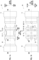
- the mold unit 10 includes a stationary mold 11 for performing injection molding, a movable mold 13 for performing blow molding, and an intermediate mold 12 for performing injection molding and blow molding.
- the intermediate mold 12 is disposed between the stationary mold 11 and the movable mold 13.
- the mold unit 10 performs injection molding in a state in which the stationary mold 11 and the intermediate mold 12 are closed, and performs blow molding in a state in which the intermediate mold 12 and the movable mold 13 are closed.
- a guide pin 142 for positioning with respect to the stationary mold 11 is provided on the rotating frame 14.
- the guide pin 142 is a columnar member that protrudes toward the first side in the first direction on the rotating frame 14 on each of the third side and the fourth side in the second direction.
- the guide pin 142 is fixed in a state of being fitted into a through-hole that penetrates through a protrusion 141 provided on the rotating frame 14 having a quadrangular columnar shape. Since the guide pin 142 need only be fixed to the protrusion 141 of the rotating frame 14, the guide pin 142 may be integrally molded with the protrusion 141 as a part of the rotating frame 14.
- a guide bush 112 that is a through-hole formed in a cylindrical shape for positioning with respect to the rotating frame 14 is formed in the stationary mold 11 on each of the third side and the fourth side in the second direction.
- the guide bush 112 is a through-hole that penetrates through a protrusion 111, which is provided on the stationary mold 11 having a quadrangular columnar shape on each of the third side and the fourth side in the second direction, in the first direction.
- the guide bush 112 is formed to be fitted with the guide pin 142 of the rotating frame 14. That is, the guide bush 112 is formed to have the same diameter size as or a slightly larger diameter size than a diameter size of the guide pin 142.
- the intermediate mold 12 and the movable mold 13 are installed in this order at an interval on the second side in the first direction with respect to the stationary mold 11, which serves as a reference for positioning.
- a movement enabling member 18 made of a so-called linear guide, a slide rail, or the like is installed in advance at an installation location of the intermediate mold 12 and the movable mold 13 to enable each of the intermediate mold 12 and the movable mold 13 to move in the first direction.
- the positioning of the intermediate mold 12 with respect to the stationary mold 11 is performed using the following method.
- a position where the through-hole 102 through which the bolt 103 passes is formed is not particularly limited and need only be any position where the positioning jig 1 can be stably fixed to the intermediate die 15.
- the through-hole 102 through which the bolt 103 passes is formed at two locations, on the top side and the bottom side in the top-bottom direction, near the central part of the positioning jig 1 in the second direction.
- the head portion of the bolt 103 does not protrude toward the first side from a surface 106 of the positioning jig 1 on the first side in the first direction.
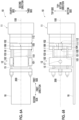
- the positioning jig 1 is formed with a through-hole 105 for positioning with respect to the stationary mold 11.
- the position where the through-hole 105 is formed in the positioning jig 1 is extremely limited in order to precisely perform the positioning.
- the through-hole 105 is formed at a position strictly corresponding to a disposition position of the guide pin 142 of the rotating frame 14 (refer to Figs. 1A and 1B ).
- "corresponding" means that the position of the guide pin 142 in the rotating frame 14 attached to the intermediate die 15 with respect to the guide bush 112 and the position of the through-hole 105 in the positioning jig 1 attached to the intermediate die 15 instead of the rotating frame 14 with respect to the guide bush 112 coincide with each other.
- the through-hole 105 of the positioning jig 1 is designed such that a diameter size d2 thereof is the same or substantially the same as a diameter size d1 of the guide pin 142 (refer to Fig. 5A ). Therefore, the through-hole 105 allows a jig pin 2 for positioning work (refer to Fig. 7 ), which will be described below, to slidably penetrate. Additionally, the positioning jig 1 is designed such that a center axis 400 of the guide pin 142 in a state in which the rotating frame 14 is attached to the intermediate mold 12 and a center axis 500 of the through-hole 105 in a state in which the positioning jig 1 is attached to the intermediate mold 12 instead of the rotating frame 14 coincide with each other.
- the extension line of the center axis 700 of the jig pin 2 and the extension line of the center axis 500 of the through-hole 105 do not coincide with each other.
- the one end of the single jig pin 2 cannot be fitted into the through-hole 105 of the positioning jig 1 in a state in which the other end is fitted into the guide bush 112 of the stationary mold 11.
- the worker performs a work of adjusting the position of the intermediate mold 12 with respect to the stationary mold 11. Specifically, first, the worker moves the intermediate mold 12, which is close to the stationary mold 11, toward the second side in the first direction to separate the stationary mold 11 and the intermediate mold 12 from each other, thereby forming a working space of several centimeters to several tens of centimeters between the stationary mold 11 and the intermediate mold 12.
- the worker inserts a jig pin 21 into the through-hole 105 of the positioning jig 1 and inserts a jig pin 22 into the guide bush 112 of the stationary mold 11.
- the jig pins 21 and 22 may be inserted from the first side toward the second side in the first direction or may be inserted from the second side toward the first side in the first direction.
- the worker slides the jig pin 21 to the first side in the first direction with respect to the through-hole 105 and slides the jig pin 22 to the second side in the first direction with respect to the guide bush 112, thereby bringing the jig pin 21 and the jig pin 22 into contact with each other.
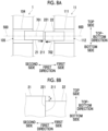
- Fig. 8A shows a state immediately before the jig pin 21 and the jig pin 22 come into contact with each other.
- the worker brings a surface 211 of an end portion of the jig pin 21 on the first side in the first direction and a surface 221 of an end portion of the jig pin 22 on the second side in the first direction into contact with each other. Then, the worker uses a measuring device such as a dial gauge to measure an amount of deviation between the center axes at a contact portion between the jig pin 21 and the jig pin 22. Specifically, as shown in Fig. 8B , an amount of positional deviation between a center axis 701 of the jig pin 21 and a center axis 702 of the jig pin 22 is measured.
- Fig. 8B shows an amount of deviation x in the top-bottom direction.
- the worker adjusts the disposition position or the number of the position adjustment members disposed between the intermediate mold 12 and the movement enabling member 18 based on the direction and degree of positional deviation quantitatively identified. Consequently, the positional deviation of the intermediate mold 12 with respect to the stationary mold 11 is corrected.
- the worker repeatedly performs a work of bringing the jig pin 21 and the jig pin 22 into contact with each other and measuring positional deviation, and a work of adjusting the disposition position or the number of the position adjustment members, thereby positioning the intermediate mold 12 with respect to the stationary mold 11.
- the stationary mold 11 and the intermediate mold 12 can be assembled in a state in which the positioning of the intermediate mold 12 with respect to the stationary mold 11 is correct.
- the worker When the positioning of the intermediate mold 12 with respect to the stationary mold 11 is completed, the worker performs the positioning of the movable mold 13 (refer to Figs. 1A and 1B ) with respect to the intermediate mold 12.
- the same method as that in the positioning of the intermediate mold 12 with respect to the stationary mold 11 can be used for the positioning of the movable mold 13 with respect to the intermediate mold 12. That is, although not shown, the positioning jig 1 according to the present embodiment is disposed between the intermediate mold 12 with the rotating frame 14 removed therefrom and the movable mold 13, and the positioning is performed using one or a plurality of jig pins 2.
- the intermediate mold 12 and the movable mold 13 can be assembled in a state in which the positioning of the movable mold 13 with respect to the intermediate mold 12 is correct.
- the mold unit can be assembled in a state in which the extension lines of the center lines of the stationary mold 11, the intermediate mold 12, and the movable mold 13 coincide with each other.
- the positioning jig to which the present invention is applied need only have the following configuration and can take various embodiments.
- the positioning jig 1 is a positioning jig that is disposed instead of the rotating frame 14 of the intermediate mold 12, the rotating frame 14 being disposed between the stationary mold 11 and the intermediate die 15 of the intermediate mold 12, in which the through-hole 105 is formed at a position corresponding to the disposition position of the guide pin 142 that is provided on the stationary mold 11 or the rotating frame 14 for positioning between the stationary mold 11 and the rotating frame 14, the through-hole 105 having the same or substantially the same diameter size as the diameter size of the guide pin 142 and having the center axis with the same direction as the direction of the center axis of the guide pin 142, and the through-hole 105 allows the jig pin 2, which slidably penetrates through the guide bush 112 to be fitted with the guide pin 142, to slidably penetrate.
- the worker inserts the jig pin 21 and the jig pin 22 into the through-hole 105 and the guide bush 112, respectively, and measures the magnitude of the positional deviation by bringing the jig pin 21 and the jig pin 22 into contact with each other, so that it is possible to quantitatively identify the magnitude of the positional deviation of the intermediate mold 12 with respect to the stationary mold 11. Further, it is also possible to measure the parallelism between the stationary mold 11 and the intermediate mold 12.
- one end of the jig pin 2, with the other end inserted into the guide bush 112 may be insertable into the through-hole 105, and in a state in which the positioning between the stationary mold 11 and the rotating frame 14 is incorrect, the one end of the jig pin 2, with the other end inserted into the guide bush 112, may not be insertable into the through-hole 105.
- the worker can easily determine that the positioning is in a correct state when the one end of the single jig pin 2 can be fitted into the through-hole 105 in a state in which the other end is fitted into the guide bush 112, and that the positioning is not in a correct state when the one end of the single jig pin 2 cannot be fitted into the through-hole 105.
Landscapes
- Engineering & Computer Science (AREA)
- Mechanical Engineering (AREA)
- Manufacturing & Machinery (AREA)
- Moulds For Moulding Plastics Or The Like (AREA)
- Injection Moulding Of Plastics Or The Like (AREA)
Applications Claiming Priority (1)
| Application Number | Priority Date | Filing Date | Title |
|---|---|---|---|
| JP2023222937A JP2025104818A (ja) | 2023-12-28 | 2023-12-28 | 位置決め治具、および位置決め方法 |
Publications (1)
| Publication Number | Publication Date |
|---|---|
| EP4578624A1 true EP4578624A1 (de) | 2025-07-02 |
Family
ID=93379054
Family Applications (1)
| Application Number | Title | Priority Date | Filing Date |
|---|---|---|---|
| EP24210527.8A Pending EP4578624A1 (de) | 2023-12-28 | 2024-11-04 | Positioniervorrichtung und positionierverfahren |
Country Status (4)
| Country | Link |
|---|---|
| US (1) | US20250214289A1 (de) |
| EP (1) | EP4578624A1 (de) |
| JP (1) | JP2025104818A (de) |
| CN (1) | CN120228853A (de) |
Citations (4)
| Publication number | Priority date | Publication date | Assignee | Title |
|---|---|---|---|---|
| DE4233894A1 (de) * | 1992-10-08 | 1994-04-14 | Hasco Normalien Hasenclever Co | Spritzgieß- oder Preßwerkzeug zur Verarbeitung von Kunststoffmassen |
| DE29724134U1 (de) * | 1997-07-23 | 2000-03-23 | EDEGS Formenbau GmbH, 71691 Freiberg | Werkzeug für Spritz- oder Druckguss |
| JP4283181B2 (ja) | 2004-07-28 | 2009-06-24 | 住友重機械工業株式会社 | 吹込成形方法 |
| US20090252826A1 (en) * | 2008-04-04 | 2009-10-08 | Samsung Electronics Co., Ltd | Injection molding machine |
-
2023
- 2023-12-28 JP JP2023222937A patent/JP2025104818A/ja active Pending
-
2024
- 2024-10-11 CN CN202411414499.0A patent/CN120228853A/zh active Pending
- 2024-11-04 EP EP24210527.8A patent/EP4578624A1/de active Pending
- 2024-11-12 US US18/944,027 patent/US20250214289A1/en active Pending
Patent Citations (4)
| Publication number | Priority date | Publication date | Assignee | Title |
|---|---|---|---|---|
| DE4233894A1 (de) * | 1992-10-08 | 1994-04-14 | Hasco Normalien Hasenclever Co | Spritzgieß- oder Preßwerkzeug zur Verarbeitung von Kunststoffmassen |
| DE29724134U1 (de) * | 1997-07-23 | 2000-03-23 | EDEGS Formenbau GmbH, 71691 Freiberg | Werkzeug für Spritz- oder Druckguss |
| JP4283181B2 (ja) | 2004-07-28 | 2009-06-24 | 住友重機械工業株式会社 | 吹込成形方法 |
| US20090252826A1 (en) * | 2008-04-04 | 2009-10-08 | Samsung Electronics Co., Ltd | Injection molding machine |
Also Published As
| Publication number | Publication date |
|---|---|
| US20250214289A1 (en) | 2025-07-03 |
| JP2025104818A (ja) | 2025-07-10 |
| CN120228853A (zh) | 2025-07-01 |
Similar Documents
| Publication | Publication Date | Title |
|---|---|---|
| JPS5838258B2 (ja) | 金型の型合せ方法及び型合せ装置 | |
| US11318576B2 (en) | Component production method and component production system | |
| KR100838787B1 (ko) | 인서트사출용 슬라이드코어조립체와 이를 구비한금형조립체 및 이를 이용한 인서트사출방법 | |
| EP2886296B1 (de) | Blasformeinheit, blasformmaschine und verfahren zur befestigung der blasformeinheit | |
| EP3326732B1 (de) | Klemmvorrichtung zum spritzgiessen von wachsmustern und zugehöriges verfahren | |
| EP4578624A1 (de) | Positioniervorrichtung und positionierverfahren | |
| US10300641B2 (en) | Cylindrical article made of fiber-reinforced resin material, injection molding mold thereof, and injection molding method | |
| JP5163785B2 (ja) | カム装置の工具取付け面に加工工具を固定するための方法及びカム装置を具備したプレス金型装置の製造方法 | |
| JP5478287B2 (ja) | 射出成形機の金型取付部材および金型取付方法 | |
| CN119703696B (zh) | 氧传感器芯片组装模组及氧传感器组装设备 | |
| CN1644349B (zh) | 注射成型机及注射成型机的对中方法 | |
| JPH06278141A (ja) | プラスチック成形装置 | |
| KR101883094B1 (ko) | 펀칭 장치용 형맞춤 세트, 펀칭 장치의 형맞춤 방법 및 프레스 제품의 제조 방법 | |
| CN111204003A (zh) | 滑动型芯进退机构和具有该机构的模具装置 | |
| JP2024161705A (ja) | バーリング加工装置及びバーリング加工方法 | |
| JP2022010436A (ja) | 打抜き装置、および方法 | |
| CN220698040U (zh) | 一种双面倒角模具 | |
| JP4862214B2 (ja) | カム装置の工具取付け面に加工工具を固定するための方法及びカム装置を具備したプレス金型装置の製造方法 | |
| CN113426905B (zh) | 高同心度铆合装置 | |
| EP2777843B1 (de) | Verfahren und Vorrichtung für das Verfahren zur Herstellung eines Gusswerkstücks | |
| KR101981538B1 (ko) | 이동형 단조프레스 베드 교정장치 | |
| JP2000102839A (ja) | 圧造成形機 | |
| JP2008055807A (ja) | 樹脂ローラ成形用金型及び樹脂ローラ | |
| JPS642455B2 (de) | ||
| JP2007152619A (ja) | 射出成形用金型及びレンズ鏡筒 |
Legal Events
| Date | Code | Title | Description |
|---|---|---|---|
| PUAI | Public reference made under article 153(3) epc to a published international application that has entered the european phase |
Free format text: ORIGINAL CODE: 0009012 |
|
| STAA | Information on the status of an ep patent application or granted ep patent |
Free format text: STATUS: EXAMINATION IS IN PROGRESS |
|
| 17P | Request for examination filed |
Effective date: 20241104 |
|
| AK | Designated contracting states |
Kind code of ref document: A1 Designated state(s): AL AT BE BG CH CY CZ DE DK EE ES FI FR GB GR HR HU IE IS IT LI LT LU LV MC ME MK MT NL NO PL PT RO RS SE SI SK SM TR |