EP4565019A1 - Wärmeleitende struktur, elektronische vorrichtung und endgerät - Google Patents
Wärmeleitende struktur, elektronische vorrichtung und endgerät Download PDFInfo
- Publication number
- EP4565019A1 EP4565019A1 EP22955306.0A EP22955306A EP4565019A1 EP 4565019 A1 EP4565019 A1 EP 4565019A1 EP 22955306 A EP22955306 A EP 22955306A EP 4565019 A1 EP4565019 A1 EP 4565019A1
- Authority
- EP
- European Patent Office
- Prior art keywords
- thermally conductive
- insulating ring
- conductive structure
- conductive part
- electronic device
- Prior art date
- Legal status (The legal status is an assumption and is not a legal conclusion. Google has not performed a legal analysis and makes no representation as to the accuracy of the status listed.)
- Pending
Links
Images





Classifications
-
- H—ELECTRICITY
- H05—ELECTRIC TECHNIQUES NOT OTHERWISE PROVIDED FOR
- H05K—PRINTED CIRCUITS; CASINGS OR CONSTRUCTIONAL DETAILS OF ELECTRIC APPARATUS; MANUFACTURE OF ASSEMBLAGES OF ELECTRICAL COMPONENTS
- H05K7/00—Constructional details common to different types of electric apparatus
- H05K7/20—Modifications to facilitate cooling, ventilating, or heating
- H05K7/20845—Modifications to facilitate cooling, ventilating, or heating for automotive electronic casings
- H05K7/20854—Heat transfer by conduction from internal heat source to heat radiating structure
-
- H—ELECTRICITY
- H10—SEMICONDUCTOR DEVICES; ELECTRIC SOLID-STATE DEVICES NOT OTHERWISE PROVIDED FOR
- H10W—GENERIC PACKAGES, INTERCONNECTIONS, CONNECTORS OR OTHER CONSTRUCTIONAL DETAILS OF DEVICES COVERED BY CLASS H10
- H10W40/00—Arrangements for thermal protection or thermal control
- H10W40/70—Fillings or auxiliary members in containers or in encapsulations for thermal protection or control
-
- H—ELECTRICITY
- H10—SEMICONDUCTOR DEVICES; ELECTRIC SOLID-STATE DEVICES NOT OTHERWISE PROVIDED FOR
- H10W—GENERIC PACKAGES, INTERCONNECTIONS, CONNECTORS OR OTHER CONSTRUCTIONAL DETAILS OF DEVICES COVERED BY CLASS H10
- H10W40/00—Arrangements for thermal protection or thermal control
- H10W40/20—Arrangements for cooling
- H10W40/25—Arrangements for cooling characterised by their materials
-
- H—ELECTRICITY
- H10—SEMICONDUCTOR DEVICES; ELECTRIC SOLID-STATE DEVICES NOT OTHERWISE PROVIDED FOR
- H10W—GENERIC PACKAGES, INTERCONNECTIONS, CONNECTORS OR OTHER CONSTRUCTIONAL DETAILS OF DEVICES COVERED BY CLASS H10
- H10W40/00—Arrangements for thermal protection or thermal control
- H10W40/20—Arrangements for cooling
- H10W40/25—Arrangements for cooling characterised by their materials
- H10W40/251—Organics
-
- H—ELECTRICITY
- H10—SEMICONDUCTOR DEVICES; ELECTRIC SOLID-STATE DEVICES NOT OTHERWISE PROVIDED FOR
- H10W—GENERIC PACKAGES, INTERCONNECTIONS, CONNECTORS OR OTHER CONSTRUCTIONAL DETAILS OF DEVICES COVERED BY CLASS H10
- H10W40/00—Arrangements for thermal protection or thermal control
- H10W40/20—Arrangements for cooling
- H10W40/25—Arrangements for cooling characterised by their materials
- H10W40/257—Arrangements for cooling characterised by their materials having a heterogeneous or anisotropic structure, e.g. powder or fibres in a matrix, wire mesh or porous structures
Definitions
- This application relates to the field of heat dissipation structure technologies, and in particular, to a thermally conductive structure, an electronic device, and a terminal.
- a computing capability of a chip is continuously improved, power consumption is greatly increased, and a size of the chip develops toward miniaturization.
- the chip generates an increasing amount of heat, and a density of the heat is increasingly high, which pose a relatively high challenge to a heat dissipation capability of the chip.
- a heat sink is usually used to dissipate heat for the chip.
- a thermally conductive layer needs to be disposed between the heat sink and the chip.
- a thermal conduction capability of the thermally conductive layer has relatively important impact on the heat dissipation capability of the chip.
- structural reliability of the thermally conductive layer is also relatively important, so that the thermally conductive layer can be relatively reliable and not likely to be damaged when an electronic device vibrates or another case occurs.
- This application provides a thermally conductive structure, an electronic device, and a terminal.
- An insulating ring protects a thermally conductive part, so that the thermally conductive part may be made of a thermally conductive material, to improve thermal conduction efficiency of the thermally conductive structure.
- this application provides a thermally conductive structure.
- the thermally conductive structure includes a thermally conductive part and an insulating ring.
- the thermally conductive part is located in the insulating ring.
- An upper side and a lower side of the thermally conductive part are at least partially exposed, so that the thermally conductive part can be in contact with a heating component and a heat sink on the two sides to conduct heat.
- the insulating ring may protect the thermally conductive part around a periphery of the thermally conductive part.
- the thermally conductive part may be disposed as a thermally conductive part of a high thermally conductive material, that is, may be a thermally conductive part made of an electrically conductive material.
- the insulating ring is an enclosed ring, or the insulating ring is provided with an opening.
- the insulating ring may be the enclosed ring, and is disposed completely around the thermally conductive part. In this solution, the insulating ring is disposed completely around the thermally conductive part. In this way, the thermally conductive part is not likely to expose from the insulating ring.
- the insulating ring may be provided with the opening. After the thermally conductive structure is installed in an electronic device, the opening of the insulating ring may absorb deformation, so that the insulating ring is not likely to wrinkle or be pulled. Specifically, there may be one or more openings.
- the thermally conductive structure When the thermally conductive structure is specifically disposed, the thermally conductive structure includes a first side and a second side that are opposite to each other. On the first side of the thermally conductive structure, a surface of the thermally conductive part and a surface of the insulating ring are in a same plane. On the second side of the thermally conductive structure, a surface of the thermally conductive part and a surface of the insulating ring are in a same plane. In other words, a thickness of the thermally conductive part and a thickness of the insulating ring are the same, and both the two sides of the thermally conductive structure are planes.
- This solution is applicable to a scenario in which one side of the heat sink is a plane and one side of the heating component is also a plane.
- the thermally conductive structure is applicable to a case in which one side of the heating component is not a plane, or a case in which one side of the heat sink is not a plane. Even if a structure on one side is not the plane, it can be ensured that the thermally conductive part is sealed by using the insulating ring, to protect the thermally conductive part and reduce a risk of a short circuit.
- the insulating ring protrudes from a surface of the thermally conductive part.
- the insulating ring protrudes from a surface of the thermally conductive part.
- the insulating ring may be fastened to the thermally conductive part.
- the thermally conductive part and the insulating ring are separately manufactured and then fastened.
- the insulating ring and the thermally conductive part may be fastened and bonded through bonding.
- the insulating ring and the thermally conductive part are of an integrated structure.
- reliability of a connection between the insulating ring and the thermally conductive part can be improved, so that the thermally conductive part is not likely to be damaged.
- the thermally conductive part and the insulating ring may absorb deformation of the thermally conductive part and the insulating ring, or may be configured to adapt to a specific structure of the electronic device.
- the thermally conductive part and the insulating ring may be two independent components, and are separately manufactured, transported, and installed.
- a material of the insulating ring may be at least one of foam, rubber, or sealant. Costs are relatively low and manufacture is convenient.
- the insulating ring may be made of a thermally conductive material, and the thermally conductive material is specifically an insulating material.
- a thermally conductive area of the thermally conductive structure can be improved. This helps improve thermal conduction efficiency and a thermal conduction capability of the thermally conductive structure.
- a material of the insulating ring may specifically include a thermally conductive gel, a thermally conductive insulating tape, a thermally conductive adhesive, or a thermally conductive insulating film.
- a thermally conductive coefficient of the thermally conductive material may be less than that of the thermally conductive part, but still has specific thermal conductivity.
- the thermally conductive coefficient of the thermally conductive part is greater than or equal to 10 W/(m ⁇ K). Specifically, the thermally conductive coefficient of the thermally conductive part may alternatively be greater than or equal to 30 W/(m ⁇ K). In this case, the thermal conduction efficiency of the thermally conductive structure can be improved.
- a specific material of the thermally conductive part includes carbon fiber or graphene.
- both a shape of the thermally conductive part and a shape of the insulating ring are not limited.
- an edge shape of the thermally conductive part may be the same as an inner edge shape of the insulating ring. In this solution, cooperation between the thermally conductive part and the insulating ring can be improved.
- the shape may be any possible shape such as a triangle, a square, a polygon, a circle, an ellipse, or an abnormal shape.
- this application further provides an electronic device.
- the electronic device includes a heating component, a heat sink, and the thermally conductive structure in the first aspect.
- the thermally conductive structure is disposed between the heating component and the heat sink, and is configured to conduct heat of the heating component to the heat sink.
- the thermally conductive structure in this solution has relatively high thermal conduction efficiency and relatively high reliability, and can reduce a risk of a short circuit.
- the thermally conductive structure When the thermally conductive structure is specifically disposed, one side of an insulating ring is disposed in contact with the heating component, and the other side is disposed in contact with the heat sink. In this way, the thermally conductive part is enclosed among the heating component, the insulating ring, and the heat sink, so that the thermally conductive part is not likely to fall into a circuit region of the electronic device when the thermally conductive part ages or is damaged. Therefore, a risk of a short circuit is reduced.
- the heating component is disposed on a circuit board
- one side of the insulating ring may be disposed in contact with the circuit board, and the other side of the insulating ring may be disposed in contact with the heat sink.
- the thermally conductive part is enclosed among the circuit board, the insulating ring, and the heat sink, so that the thermally conductive part is not likely to fall into a circuit region of the electronic device when the thermally conductive part ages or is damaged. Therefore, a risk of a short circuit is reduced.
- the electronic device is a vehicle-mounted electronic device. Vibration or the like easily occurs in a running process of a vehicle, but the thermally conductive structure in this solution is not likely to fall off in a vibration scenario. Therefore, heat dissipation efficiency of the vehicle-mounted electronic device can be effectively improved.
- this application further provides a terminal.
- the terminal includes the electronic device in the second aspect.
- the terminal has a relatively strong heat dissipation capability and a relatively good operating status.
- a requirement for heat dissipation of heating components such as a chip is increasingly obvious.
- heat dissipation of the heating component is usually implemented by using a heat sink.
- a thermally conductive structure needs to be disposed between the heating component and the heat sink.
- the thermally conductive structure has thermal conductivity, and may conduct heat of the heating component to the heat sink for heat dissipation.
- the thermally conductive structure is usually flexible, so that a relatively reliable contact between the heating component and the heat sink can be achieved, and a contact area is increased, to improve the heat dissipation effect of the heating component.
- a material of the thermally conductive structure includes an insulation material and an electrically conductive material.
- a thermally conductive structure with relatively good thermal conductivity is usually a thermally conductive structure of the electrically conductive material.
- the heating component such as the chip is usually used in an electrical structure such as a circuit board. Therefore, in some scenarios, if the thermally conductive structure is of the electrically conductive material, a short circuit is likely to occur.
- the thermally conductive structure is easily damaged. A part of a thermally conductive structure that is damaged is likely to fall off, and a thermally conductive structure that falls off falls on a circuit structure such as the circuit board. In this case, the short circuit is likely to be caused. Therefore, this application provides a thermally conductive structure and an electronic device.
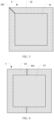
- FIG. 1 is a schematic diagram of a top-view structure of a thermally conductive structure according to an embodiment of this application.
- FIG. 2 is a schematic diagram of a sectional-view structure of a thermally conductive structure according to an embodiment of this application.
- the thermally conductive structure 1 in this embodiment of this application includes a thermally conductive part 11 and an insulating ring 12.
- the thermally conductive part 11 is located in the insulating ring 12.
- the insulating ring 12 is disposed around a periphery of the thermally conductive part 11, and an upper side and a lower side of the thermally conductive part 11 are at least partially exposed.
- the thermally conductive part 11 can be in contact with a heating component and a heat sink on the two sides to conduct heat.
- the upper side and the lower side of the thermally conductive part 11 are separately a side that is of the thermally conductive part 11 and that is in contact with the heating component and a side that is of the thermally conductive part 11 and that is in contact with the heat sink.
- the periphery of the thermally conductive part 11 is protected by the insulating ring 12. Even if the thermally conductive structure 1 is aged or damaged, aging or damage mainly occurs on the insulating ring 12, and the internal thermally conductive part 11 is not likely to fall off.
- the thermally conductive part 11 may be disposed as a thermally conductive part 11 of a high thermally conductive material, and may be a thermally conductive part 11 made of an electrically conductive material. In this way, a thermal conduction capability of the thermally conductive structure 1 is improved, and a risk of a short circuit is not likely to be caused.
- an anti-aging capability of the insulating ring 12 may be stronger than an anti-aging capability of the thermally conductive part 11. In this way, when the thermally conductive part 11 ages, the insulating ring 12 experiences a relatively low degree of aging and is not likely to be damaged, so that protection effect for the thermally conductive part 11 is relatively good.
- mechanical strength of the insulating ring 12 may be further greater than mechanical strength of the thermally conductive part 11. In this way, the insulating ring 12 is not likely to be damaged in a vibration process. Therefore, in this solution, an antivibration capability of the thermally conductive structure 1 is relatively good.
- a material of the insulating ring 12 may be at least one of foam, rubber, and sealant.
- the materials are flexible and easy to install. In addition, the materials are easy to fabricate and costs are relatively low.
- the insulating ring 12 may alternatively be made of a thermally conductive material.
- the thermally conductive material has specific thermal conductivity. Certainly, the thermal conductivity of the thermally conductive material may be lower than thermal conductivity of the thermally conductive part 11. Therefore, the insulating ring 12 may also conduct heat, to increase a thermally conductive area of the thermally conductive structure 1, and improve thermally conductive effect of the thermally conductive structure 1.
- the thermally conductive material may be a thermally conductive gel, a thermally conductive insulating tape, a thermally conductive adhesive, or a thermally conductive insulating film.
- the thermally conductive adhesive may be formed through heat curing or room temperature curing. In other words, the thermally conductive adhesive may be a heat-curing thermally conductive adhesive or a room temperature-curing thermally conductive adhesive.
- the insulating ring 12 may alternatively be made of the thermally conductive gel or the like.
- the thermally conductive part 11 may be made of the electrically conductive material, and therefore has relatively good thermal conductivity.
- a thermally conductive coefficient of the thermally conductive part 11 is greater than or equal to 10 W/(m ⁇ K).
- the thermally conductive coefficient is heat transferred through an area of one square meter within a specific time period for a one-meter (m)-thick material with a temperature difference of one degree (K or °C) on surfaces of two sides under a stable heat transfer condition.
- the thermally conductive coefficient is in a unit of watt/meter ⁇ degree (W/(m ⁇ K)). K may be replaced with °C herein.
- the thermally conductive coefficient of the thermally conductive part 11 may be 11 W/(m ⁇ K), 15 W/(m ⁇ K), 18 W/(m ⁇ K), 20 W/(m ⁇ K), 22 W/(m ⁇ K), 25 W/(m ⁇ K), 26 W/(m ⁇ K), 30 W/(m ⁇ K), 35 W/(m ⁇ K), 40 W/(m ⁇ K), or the like. This is not listed one by one herein.
- a material of the thermally conductive part 11 includes carbon fiber or graphene. Thermal conduction capabilities of the two materials are relatively strong. This helps improve the thermal conduction capability of the thermally conductive structure 1.
- the insulating ring 12 may be an enclosed ring.
- the insulating ring 12 is not provided with an opening 121, and is disposed completely around the thermally conductive part 11.
- the insulating ring 12 is disposed completely around the thermally conductive part 11. In this way, the thermally conductive part 11 is not likely to expose from the insulating ring 12. This helps improve reliability of the thermally conductive structure 1.
- the insulating ring 12 is of an integral structure and is easy to install.
- the insulating ring 12 may be of an integrated structure.
- the enclosed ring is manufactured through a one-step forming process.
- a manufacturing process of the insulating ring 12 is simplified, and overall strength of the insulating ring 12 is relatively high.
- the insulating ring 12 may form the enclosed ring through a fixed connection such as bonding.
- a manner of forming the enclosed ring is not limited in this application, provided that the enclosed ring can be formed.
- FIG. 3 is a schematic diagram of another top-view structure of a thermally conductive structure according to an embodiment of this application.
- the insulating ring 12 is further provided with an opening 121.
- the opening of the insulating ring 12 may absorb deformation, so that the insulating ring 12 is not likely to wrinkle or be pulled.
- a size of the opening is not limited.
- a width of the opening may range from 0 millimeters to 5 millimeters.
- the width of the opening may range from 0 mm to 5 mm.
- the opening 121 is merely a gap.
- the insulating ring 12 is not connected to form an enclosed ring.
- an edge shape of the opening 121 is not limited. As shown in FIG. 3 , the edge of the opening 121 may be of a straight line shape.
- FIG. 4 is a schematic diagram of another top-view structure of a thermally conductive structure according to an embodiment of this application. As shown in FIG. 4 , in another embodiment, the edge of the opening 121 may alternatively be of a zigzag shape. In this solution, when the opening 121 is provided, a risk of exposure of the internal thermally conductive part 11 is further reduced, and reliability of the thermally conductive structure 1 is improved.
- the edge of the opening 121 may alternatively be of an arc shape, a wave shape, or the like. This is not listed one by one herein.
- a specific position of the opening 121 is not limited either.
- An example in which a shape of the thermally conductive structure 1 is a square.
- the opening 121 may be disposed at a position of a side of the thermally conductive structure 1.
- FIG. 5 is a schematic diagram of another top-view structure of a thermally conductive structure according to an embodiment of this application.
- the opening 121 may be alternatively disposed at a diagonal position of the thermally conductive structure 1.
- a quantity of the openings 121 included in the insulating ring 12 is not limited either.
- the insulating ring 12 may include one opening 121.
- FIG. 6 is a schematic diagram of another top-view structure of a thermally conductive structure according to an embodiment of this application.
- the insulating ring 12 may alternatively include two openings 121, and the two openings 121 may be disposed on two opposite sides.
- the insulating ring 12 may alternatively be provided with a plurality of openings 121, for example, three, four, or more openings 121.
- the specific shape of the thermally conductive structure 1 is not limited.
- an edge shape of the thermally conductive part 11, an inner edge shape of the insulating ring 12, and an outer edge shape of the insulating ring 12 are the same.
- each of the edge shapes is not limited.
- each of the edges is a square.
- each of the edges is a circle.
- FIG. 8 is a schematic diagram of another top-view structure of a thermally conductive structure according to an embodiment of this application.
- the edge shape of the thermally conductive part 11 and the inner edge shape of the insulating ring 12 are the same, and the outer edge shape of the insulating ring 12 may be different from the shapes.
- both the edge shape of the thermally conductive part 11 and the inner edge shape of the insulating ring 12 are circles, and the outer edge shape of the insulating ring 12 is a square.
- a relatively reliable connection between the thermally conductive part 11 and the insulating ring 12 can be achieved, and the insulating ring 12 protects the thermally conductive part 11, so that the thermally conductive part 11 is not likely to expose from the insulating ring 12.
- the shapes of the thermally conductive part 11 and the insulating ring 12 may be designed based on a shape and an installation position of a heating component. This is not listed one by one in this application.
- the insulating ring 12 of the thermally conductive structure 1 is fastened to the thermally conductive part 11.
- the insulating ring 12 may be fastened to the thermal conduction through adhesive bonding or interference fit assembly.
- the thermally conductive structure 1 may be of an integrated structure, so that transportation and installation of the thermally conductive structure 1 is facilitated.
- the insulating ring 12 and the thermally conductive part 11 may further be of an integrated structure.
- the thermally conductive structure 1 is manufactured through a one-step forming process.
- the insulating ring 12 and the thermally conductive part 11 are relatively reliably fastened, so that reliability of the thermally conductive structure 1 is improved, and the thermally conductive part 11 is not likely to expose from insulation.
- FIG. 9 is a schematic diagram of another top-view structure of a thermally conductive structure according to an embodiment of this application. As shown in FIG. 9 , in another embodiment, there is further a gap 13 between a thermally conductive part 11 and an insulating ring 12. A specific width of the gap 13 is not limited, for example, may range from 0 mm to 5 mm. This solution may absorb deformation of the thermally conductive part 11 and the insulating ring 12, or may be configured to adapt to a specific structure of an electronic device. In this embodiment, the thermally conductive part 11 and the insulating ring 12 may be two independent components, and are separately manufactured, transported, and installed.
- FIG. 10 is a schematic diagram of another top-view structure of a thermally conductive structure according to an embodiment of this application.
- the gap 13 may be configured to be not completely surrounding the thermally conductive part 11.
- the gap 13 is disposed at a position of any one side, any two sides, or any three sides, and a closed annular gap.
- the gap 13 is located at two opposite sides of the thermally conductive part 11 of a quadrilateral shape.
- the gap 13 may be used to absorb the deformation of the thermally conductive part 11 and the insulating ring 12, and the thermally conductive part 11 and the insulating ring 12 may be further fastened, so that installation and transportation of the thermally conductive structure is facilitated.
- FIG. 11 is a schematic diagram of a structure of an electronic device according to an embodiment of this application.
- the electronic device includes a heating component 2, a heat sink 3, and the thermally conductive structure 1 in any one of the foregoing embodiments.
- the thermally conductive structure 1 is disposed between the heating component 2 and the heat sink 3, and specifically, two sides of the thermally conductive part 11 may be respectively in contact with the heating component 2 and heat dissipation, to transmit heat between the heating component 2 and the heat dissipation.
- a thermal conduction capability of the thermally conductive structure 1 in this embodiment is relatively strong. Therefore, a heat dissipation capability of the electronic device is relatively strong.
- the thermally conductive structure 1 is not likely to cause a short circuit of the electronic device, and helps improve reliability of the electronic device.
- one side of the insulating ring 12 is in contact with the heating component 2, and the other side is disposed in contact with the heat sink 3.
- the thermally conductive part 11 is sealed among the heating component 2, the heat sink 3, and the insulating ring 12, so that a probability that the thermally conductive part 11 is exposed to the outside may be effectively reduced, and structure reliability of the electronic device is improved.
- the thermally conductive structure 1 includes a first side 14 and a second side 15 that are opposite to each other.
- the thermally conductive structure 1 is specifically a sheet-shaped structure. Along a direction perpendicular to a surface of the thermally conductive part 11, the thermally conductive structure 1 includes the first side 14 and the second side 15 that are opposite to each other.
- the thermally conductive part 11 and a surface of the insulating ring 12 are in a same plane.
- a manufacturing process of the thermally conductive structure 1 in this solution is relatively simple. This helps simplify the manufacturing process of the thermally conductive structure 1. In addition, storage and transportation of the thermally conductive structure 1 is further facilitated.
- This solution is mainly applicable to a case in which one side of the heating component 2 is a planar structure and one side of the heat sink 3 is also a planar structure.
- FIG. 12 is a schematic diagram of another sectional-view structure of a thermally conductive structure according to an embodiment of this application.
- a thermally conductive part 11 and a surface of an insulating ring 12 are in a same plane.
- the insulating ring 12 protrudes from a surface of the thermally conductive part 11.
- the thermally conductive structure 1 is applicable to a case in which one side of a heating component 2 is not a plane, or a case in which one side of a heat sink 3 is not a plane.
- This solution is mainly applicable to a case in which one side of the heating component 2 is a planar structure and one side of the heat sink 3 is provided with a first protrusion 31, a case in which one side of the heating component 2 is provided with a second protrusion 21 and one side of the heat sink 3 is a planar structure, or a case in which the heating component 2 is disposed on a circuit board 4, the heating component 2 protrudes from the circuit board 4, and one side of the heat sink 3 is a planar structure.
- FIG. 13 is a schematic diagram of another structure of an electronic device according to an embodiment of this application.
- the heating component 2 is disposed on the circuit board 4, the heating component 2 protrudes from the circuit board 4.
- the heating component 2 is equivalent to the second protrusion 21.
- the thermally conductive structure 1 may be shown in FIG. 12 .
- the insulating ring 12 protrudes from the thermally conductive part 11, so that the second side 15 of the thermally conductive structure 1 faces one side of the circuit board 4.
- both the thermally conductive part 11 and the insulating ring 12 are disposed in contact with the heat sink 3.
- the thermally conductive part 11 On the second side 15 of the thermally conductive structure 1, the thermally conductive part 11 is disposed in contact with the heating component 2, and the insulating ring 12 is disposed in contact with the circuit board 4.
- the thermally conductive part 11 may also be sealed among the heat sink 3, the circuit board 4, and the insulating ring 12, so that the thermally conductive part 11 is not likely to expose.
- the thermally conductive structure 1 in the embodiment shown in FIG. 11 may alternatively be shown in FIG. 11 .
- the insulating ring 12 has specific elasticity, and is compressed between the heating component 2 and the heat sink 3. This solution helps improve reliability of protecting the thermally conductive part 11 by the insulating ring 12.
- FIG. 14 is a schematic diagram of another sectional-view structure of a thermally conductive structure according to an embodiment of this application.
- an insulating ring 12 protrudes from a surface of a thermally conductive part 11.
- the thermally conductive structure 1 may be adapted to a shape of one side of a heating component 2 or a shape of one side of a heat sink 3.
- This solution is mainly applicable to a case in which one side of the heating component 2 is provided with a second protrusion 21 and one side of the heat sink 3 is provided with a first protrusion 31, or a case in which the heating component 2 is disposed on a circuit board 4, the heating component 2 protrudes from the circuit board 4, and one side of the heat sink 3 is a planar structure.
- FIG. 15 is a schematic diagram of another structure of an electronic device according to an embodiment of this application.
- the heating component 2 is disposed on the circuit board 4, and the heating component 2 is provided with the second protrusion 21.
- the heat sink 3 is provided with a first protrusion 31.
- the thermally conductive structure 1 in this embodiment is shown in FIG. 14 .
- the thermally conductive structure 1 When the thermally conductive structure 1 is disposed between the heating component 2 and the heat sink 3, the first side 14 of the thermally conductive structure 1 faces one side of the heat sink 3, the thermally conductive part 11 is disposed in contact with the first protrusion 31 of the heat sink 3, and the insulating ring 12 is disposed in contact with the heat sink 3 at a position where the first protrusion 31 is not provided on the heat sink 3.
- the second side 15 of the thermally conductive structure 1 is disposed facing the heating component 2, the thermally conductive part 11 is disposed in contact with the heating component 2, and the insulating ring 12 is disposed in contact with the circuit board 4.
- the thermally conductive part 11 may also be sealed among the heat sink 3, the circuit board 4, and the insulating ring 12, so that the thermally conductive part 11 is not likely to expose.
- the thermally conductive structure 1 in the embodiment shown in FIG. 14 may alternatively be shown in FIG. 11 .
- the insulating ring 12 has specific elasticity, and is compressed between the heating component 2 and the heat sink 3. This solution helps improve reliability of protecting the thermally conductive part 11 by the insulating ring 12.
- disposed in contact with in embodiments of this application may include direct contact or indirect contact, and mainly indicates that there is no gap between two objects.
- a and B may be in direct contact, or a transition component C may alternatively be disposed between A and B.
- A is in direct contact with C, and C is in direct contact with B. In this case, there is no gap between A and B.
- a thickness of the insulating ring 12 is greater than a thickness of the thermally conductive layer.
- strength of the insulating ring 12 is relatively high, and both an anti-shock capability and an anti-aging capability are relatively strong. This solution helps improve a service life and reliability of the thermally conductive structure 1.
- the heating component 2 may be a chip.
- the electronic device may be a vehicle-mounted electronic device. Vibration or the like easily occurs in a running process of a vehicle.
- the insulating ring 12 may protect the thermally conductive part 11. Therefore. A scenario in which the vibration is severe may be better adapted. This helps improve heat dissipation performance of the vehicle-mounted electronic device of the vehicle, and a service life, performance, and the like of the vehicle-mounted electronic device are further improved.
- the terminal includes the foregoing electronic device.
- a specific type of the terminal is not limited.
- the terminal may be a communication terminal such as a server or a memory, may be a mobile terminal such as a notebook computer or a tablet computer, or may be another terminal such as a vehicle or a home device.
- the terminal has a relatively strong heat dissipation capability, and therefore has a relatively good operating capability.
Landscapes
- Physics & Mathematics (AREA)
- Thermal Sciences (AREA)
- Engineering & Computer Science (AREA)
- Microelectronics & Electronic Packaging (AREA)
- Cooling Or The Like Of Electrical Apparatus (AREA)
- Cooling Or The Like Of Semiconductors Or Solid State Devices (AREA)
Applications Claiming Priority (1)
| Application Number | Priority Date | Filing Date | Title |
|---|---|---|---|
| PCT/CN2022/113134 WO2024036525A1 (zh) | 2022-08-17 | 2022-08-17 | 一种导热结构、电子设备及终端 |
Publications (2)
| Publication Number | Publication Date |
|---|---|
| EP4565019A1 true EP4565019A1 (de) | 2025-06-04 |
| EP4565019A4 EP4565019A4 (de) | 2025-08-06 |
Family
ID=89940434
Family Applications (1)
| Application Number | Title | Priority Date | Filing Date |
|---|---|---|---|
| EP22955306.0A Pending EP4565019A4 (de) | 2022-08-17 | 2022-08-17 | Wärmeleitende struktur, elektronische vorrichtung und endgerät |
Country Status (5)
| Country | Link |
|---|---|
| US (1) | US20250194058A1 (de) |
| EP (1) | EP4565019A4 (de) |
| JP (1) | JP2025526169A (de) |
| CN (1) | CN119547576A (de) |
| WO (1) | WO2024036525A1 (de) |
Family Cites Families (16)
| Publication number | Priority date | Publication date | Assignee | Title |
|---|---|---|---|---|
| JP3502449B2 (ja) * | 1994-08-23 | 2004-03-02 | 三菱電機株式会社 | 半導体装置、及びその製造方法 |
| US6392890B1 (en) * | 2000-12-20 | 2002-05-21 | Nortel Networks Limited | Method and device for heat dissipation in an electronics system |
| US7554190B2 (en) * | 2004-12-03 | 2009-06-30 | Chris Macris | Liquid metal thermal interface material system |
| CN101052291A (zh) * | 2007-04-25 | 2007-10-10 | 陈鸿文 | 一种预先成形的板状体散热元件 |
| JP2009302556A (ja) * | 2009-08-31 | 2009-12-24 | Renesas Technology Corp | 半導体装置 |
| JP2011249681A (ja) * | 2010-05-28 | 2011-12-08 | Sony Chemical & Information Device Corp | 熱伝導性シート及び半導体装置 |
| JP5607780B2 (ja) * | 2013-03-28 | 2014-10-15 | 株式会社カネカ | グラファイト複合フィルム |
| JP2017059707A (ja) * | 2015-09-17 | 2017-03-23 | 富士通株式会社 | 積層チップ、積層チップを搭載する基板、及び積層チップの製造方法 |
| CN106455419A (zh) * | 2016-09-05 | 2017-02-22 | 珠海格力电器股份有限公司 | 一种电子设备散热结构 |
| US10319666B2 (en) * | 2017-04-19 | 2019-06-11 | International Business Machines Corporation | Thermal interface material structures including protruding surface features to reduce thermal interface material migration |
| US10319609B2 (en) * | 2017-06-21 | 2019-06-11 | International Business Machines Corporation | Adhesive-bonded thermal interface structures |
| MY209993A (en) * | 2019-02-04 | 2025-08-19 | Sony Interactive Entertainment Inc | Electronic apparatus, semiconductor device, insulating sheet, and method for manufacturing semiconductor device |
| CN113841235B (zh) * | 2019-05-28 | 2024-05-24 | 三菱电机株式会社 | 半导体模块、半导体模块的制造方法以及电力变换装置 |
| DE112019007669B4 (de) * | 2019-08-26 | 2024-12-24 | Mitsubishi Electric Corporation | Leistungshalbleiterbauelement, Verfahren zur Herstellung eines Leistungshalbleiterbauelements und Leistungswandlergerät |
| CN111675880A (zh) * | 2019-11-28 | 2020-09-18 | 哈尔滨理工大学 | 一种新型软性绝缘导热垫 |
| CN211831630U (zh) * | 2020-03-21 | 2020-10-30 | 宁波吉品科技有限公司 | 散热式射频测试平台 |
-
2022
- 2022-08-17 CN CN202280097757.XA patent/CN119547576A/zh active Pending
- 2022-08-17 EP EP22955306.0A patent/EP4565019A4/de active Pending
- 2022-08-17 JP JP2025508980A patent/JP2025526169A/ja active Pending
- 2022-08-17 WO PCT/CN2022/113134 patent/WO2024036525A1/zh not_active Ceased
-
2025
- 2025-02-17 US US19/055,066 patent/US20250194058A1/en active Pending
Also Published As
| Publication number | Publication date |
|---|---|
| US20250194058A1 (en) | 2025-06-12 |
| CN119547576A (zh) | 2025-02-28 |
| WO2024036525A1 (zh) | 2024-02-22 |
| JP2025526169A (ja) | 2025-08-07 |
| EP4565019A4 (de) | 2025-08-06 |
Similar Documents
| Publication | Publication Date | Title |
|---|---|---|
| JP6982738B2 (ja) | 複合シートおよびこれを用いた電池パック | |
| JP4892527B2 (ja) | 電子制御装置 | |
| WO2022242510A1 (zh) | 散热装置及车载模块 | |
| CN102246616A (zh) | 电路模块 | |
| JP2010057345A (ja) | 電子制御装置 | |
| WO2019111655A1 (ja) | 電子制御装置 | |
| CN214123955U (zh) | 电池模块及其电池管理系统、无人机 | |
| US20190104644A1 (en) | Electronic device | |
| CN215813334U (zh) | 电子装置、终端设备及雷达 | |
| WO2016006317A1 (ja) | 半導体遮断器の放熱構造 | |
| EP4565019A1 (de) | Wärmeleitende struktur, elektronische vorrichtung und endgerät | |
| JP2001358259A (ja) | 半導体パッケージ | |
| CN107943243A (zh) | 一种静音、散热、易安装的加固服务器 | |
| CN218071925U (zh) | 一种组合型散热屏蔽结构及电子组件 | |
| CN214068517U (zh) | 平面变压器 | |
| WO2024150331A1 (ja) | 電子制御装置 | |
| WO2023098503A1 (zh) | 一种屏蔽结构、封装体、板级架构、散热器及电子设备 | |
| CN219780747U (zh) | 汽车中央域控制器及其汽车 | |
| CN217468396U (zh) | 芯片封装结构 | |
| CN118102681B (zh) | 电子设备 | |
| US11563836B2 (en) | Electronic device with cylindrical battery | |
| CN218585971U (zh) | 芯片封装结构 | |
| JP7836228B2 (ja) | 電子制御装置 | |
| CN220121128U (zh) | 光机以及投影系统 | |
| CN224006697U (zh) | 声学装置封装结构 |
Legal Events
| Date | Code | Title | Description |
|---|---|---|---|
| STAA | Information on the status of an ep patent application or granted ep patent |
Free format text: STATUS: THE INTERNATIONAL PUBLICATION HAS BEEN MADE |
|
| PUAI | Public reference made under article 153(3) epc to a published international application that has entered the european phase |
Free format text: ORIGINAL CODE: 0009012 |
|
| STAA | Information on the status of an ep patent application or granted ep patent |
Free format text: STATUS: REQUEST FOR EXAMINATION WAS MADE |
|
| 17P | Request for examination filed |
Effective date: 20250225 |
|
| AK | Designated contracting states |
Kind code of ref document: A1 Designated state(s): AL AT BE BG CH CY CZ DE DK EE ES FI FR GB GR HR HU IE IS IT LI LT LU LV MC MK MT NL NO PL PT RO RS SE SI SK SM TR |
|
| A4 | Supplementary search report drawn up and despatched |
Effective date: 20250708 |
|
| RIC1 | Information provided on ipc code assigned before grant |
Ipc: H05K 7/20 20060101AFI20250702BHEP Ipc: H01L 23/367 20060101ALI20250702BHEP Ipc: H01L 23/373 20060101ALI20250702BHEP Ipc: H01L 23/42 20060101ALI20250702BHEP |
|
| DAV | Request for validation of the european patent (deleted) | ||
| DAX | Request for extension of the european patent (deleted) |