EP4545127A2 - Nasenkanülenanordnungen und zugehörige teile - Google Patents
Nasenkanülenanordnungen und zugehörige teile Download PDFInfo
- Publication number
- EP4545127A2 EP4545127A2 EP25158113.8A EP25158113A EP4545127A2 EP 4545127 A2 EP4545127 A2 EP 4545127A2 EP 25158113 A EP25158113 A EP 25158113A EP 4545127 A2 EP4545127 A2 EP 4545127A2
- Authority
- EP
- European Patent Office
- Prior art keywords
- cannula
- manifold
- nasal
- tube
- supply tube
- Prior art date
- Legal status (The legal status is an assumption and is not a legal conclusion. Google has not performed a legal analysis and makes no representation as to the accuracy of the status listed.)
- Pending
Links
Images


Classifications
-
- A—HUMAN NECESSITIES
- A61—MEDICAL OR VETERINARY SCIENCE; HYGIENE
- A61M—DEVICES FOR INTRODUCING MEDIA INTO, OR ONTO, THE BODY; DEVICES FOR TRANSDUCING BODY MEDIA OR FOR TAKING MEDIA FROM THE BODY; DEVICES FOR PRODUCING OR ENDING SLEEP OR STUPOR
- A61M16/00—Devices for influencing the respiratory system of patients by gas treatment, e.g. ventilators; Tracheal tubes
- A61M16/06—Respiratory or anaesthetic masks
- A61M16/0666—Nasal cannulas or tubing
-
- A—HUMAN NECESSITIES
- A61—MEDICAL OR VETERINARY SCIENCE; HYGIENE
- A61J—CONTAINERS SPECIALLY ADAPTED FOR MEDICAL OR PHARMACEUTICAL PURPOSES; DEVICES OR METHODS SPECIALLY ADAPTED FOR BRINGING PHARMACEUTICAL PRODUCTS INTO PARTICULAR PHYSICAL OR ADMINISTERING FORMS; DEVICES FOR ADMINISTERING FOOD OR MEDICINES ORALLY; BABY COMFORTERS; DEVICES FOR RECEIVING SPITTLE
- A61J15/00—Feeding-tubes for therapeutic purposes
- A61J15/0003—Nasal or oral feeding-tubes, e.g. tube entering body through nose or mouth
-
- A—HUMAN NECESSITIES
- A61—MEDICAL OR VETERINARY SCIENCE; HYGIENE
- A61M—DEVICES FOR INTRODUCING MEDIA INTO, OR ONTO, THE BODY; DEVICES FOR TRANSDUCING BODY MEDIA OR FOR TAKING MEDIA FROM THE BODY; DEVICES FOR PRODUCING OR ENDING SLEEP OR STUPOR
- A61M16/00—Devices for influencing the respiratory system of patients by gas treatment, e.g. ventilators; Tracheal tubes
- A61M16/0003—Accessories therefor, e.g. sensors, vibrators, negative pressure
-
- A—HUMAN NECESSITIES
- A61—MEDICAL OR VETERINARY SCIENCE; HYGIENE
- A61M—DEVICES FOR INTRODUCING MEDIA INTO, OR ONTO, THE BODY; DEVICES FOR TRANSDUCING BODY MEDIA OR FOR TAKING MEDIA FROM THE BODY; DEVICES FOR PRODUCING OR ENDING SLEEP OR STUPOR
- A61M16/00—Devices for influencing the respiratory system of patients by gas treatment, e.g. ventilators; Tracheal tubes
- A61M16/0057—Pumps therefor
- A61M16/0066—Blowers or centrifugal pumps
-
- A—HUMAN NECESSITIES
- A61—MEDICAL OR VETERINARY SCIENCE; HYGIENE
- A61M—DEVICES FOR INTRODUCING MEDIA INTO, OR ONTO, THE BODY; DEVICES FOR TRANSDUCING BODY MEDIA OR FOR TAKING MEDIA FROM THE BODY; DEVICES FOR PRODUCING OR ENDING SLEEP OR STUPOR
- A61M16/00—Devices for influencing the respiratory system of patients by gas treatment, e.g. ventilators; Tracheal tubes
- A61M16/06—Respiratory or anaesthetic masks
- A61M16/0605—Means for improving the adaptation of the mask to the patient
- A61M16/0616—Means for improving the adaptation of the mask to the patient with face sealing means comprising a flap or membrane projecting inwards, such that sealing increases with increasing inhalation gas pressure
- A61M16/0622—Means for improving the adaptation of the mask to the patient with face sealing means comprising a flap or membrane projecting inwards, such that sealing increases with increasing inhalation gas pressure having an underlying cushion
-
- A—HUMAN NECESSITIES
- A61—MEDICAL OR VETERINARY SCIENCE; HYGIENE
- A61M—DEVICES FOR INTRODUCING MEDIA INTO, OR ONTO, THE BODY; DEVICES FOR TRANSDUCING BODY MEDIA OR FOR TAKING MEDIA FROM THE BODY; DEVICES FOR PRODUCING OR ENDING SLEEP OR STUPOR
- A61M16/00—Devices for influencing the respiratory system of patients by gas treatment, e.g. ventilators; Tracheal tubes
- A61M16/06—Respiratory or anaesthetic masks
- A61M16/0605—Means for improving the adaptation of the mask to the patient
- A61M16/0633—Means for improving the adaptation of the mask to the patient with forehead support
-
- A—HUMAN NECESSITIES
- A61—MEDICAL OR VETERINARY SCIENCE; HYGIENE
- A61M—DEVICES FOR INTRODUCING MEDIA INTO, OR ONTO, THE BODY; DEVICES FOR TRANSDUCING BODY MEDIA OR FOR TAKING MEDIA FROM THE BODY; DEVICES FOR PRODUCING OR ENDING SLEEP OR STUPOR
- A61M16/00—Devices for influencing the respiratory system of patients by gas treatment, e.g. ventilators; Tracheal tubes
- A61M16/06—Respiratory or anaesthetic masks
- A61M16/0666—Nasal cannulas or tubing
- A61M16/0672—Nasal cannula assemblies for oxygen therapy
- A61M16/0677—Gas-saving devices therefor
-
- A—HUMAN NECESSITIES
- A61—MEDICAL OR VETERINARY SCIENCE; HYGIENE
- A61M—DEVICES FOR INTRODUCING MEDIA INTO, OR ONTO, THE BODY; DEVICES FOR TRANSDUCING BODY MEDIA OR FOR TAKING MEDIA FROM THE BODY; DEVICES FOR PRODUCING OR ENDING SLEEP OR STUPOR
- A61M16/00—Devices for influencing the respiratory system of patients by gas treatment, e.g. ventilators; Tracheal tubes
- A61M16/06—Respiratory or anaesthetic masks
- A61M16/0683—Holding devices therefor
-
- A—HUMAN NECESSITIES
- A61—MEDICAL OR VETERINARY SCIENCE; HYGIENE
- A61M—DEVICES FOR INTRODUCING MEDIA INTO, OR ONTO, THE BODY; DEVICES FOR TRANSDUCING BODY MEDIA OR FOR TAKING MEDIA FROM THE BODY; DEVICES FOR PRODUCING OR ENDING SLEEP OR STUPOR
- A61M16/00—Devices for influencing the respiratory system of patients by gas treatment, e.g. ventilators; Tracheal tubes
- A61M16/08—Bellows; Connecting tubes ; Water traps; Patient circuits
- A61M16/0816—Joints or connectors
- A61M16/0841—Joints or connectors for sampling
- A61M16/0858—Pressure sampling ports
-
- A—HUMAN NECESSITIES
- A61—MEDICAL OR VETERINARY SCIENCE; HYGIENE
- A61M—DEVICES FOR INTRODUCING MEDIA INTO, OR ONTO, THE BODY; DEVICES FOR TRANSDUCING BODY MEDIA OR FOR TAKING MEDIA FROM THE BODY; DEVICES FOR PRODUCING OR ENDING SLEEP OR STUPOR
- A61M16/00—Devices for influencing the respiratory system of patients by gas treatment, e.g. ventilators; Tracheal tubes
- A61M16/08—Bellows; Connecting tubes ; Water traps; Patient circuits
- A61M16/0875—Connecting tubes
-
- A—HUMAN NECESSITIES
- A61—MEDICAL OR VETERINARY SCIENCE; HYGIENE
- A61M—DEVICES FOR INTRODUCING MEDIA INTO, OR ONTO, THE BODY; DEVICES FOR TRANSDUCING BODY MEDIA OR FOR TAKING MEDIA FROM THE BODY; DEVICES FOR PRODUCING OR ENDING SLEEP OR STUPOR
- A61M16/00—Devices for influencing the respiratory system of patients by gas treatment, e.g. ventilators; Tracheal tubes
- A61M16/10—Preparation of respiratory gases or vapours
- A61M16/1075—Preparation of respiratory gases or vapours by influencing the temperature
- A61M16/1095—Preparation of respiratory gases or vapours by influencing the temperature in the connecting tubes
-
- A—HUMAN NECESSITIES
- A61—MEDICAL OR VETERINARY SCIENCE; HYGIENE
- A61M—DEVICES FOR INTRODUCING MEDIA INTO, OR ONTO, THE BODY; DEVICES FOR TRANSDUCING BODY MEDIA OR FOR TAKING MEDIA FROM THE BODY; DEVICES FOR PRODUCING OR ENDING SLEEP OR STUPOR
- A61M15/00—Inhalators
- A61M15/08—Inhaling devices inserted into the nose
- A61M15/085—Fixing means therefor
-
- A—HUMAN NECESSITIES
- A61—MEDICAL OR VETERINARY SCIENCE; HYGIENE
- A61M—DEVICES FOR INTRODUCING MEDIA INTO, OR ONTO, THE BODY; DEVICES FOR TRANSDUCING BODY MEDIA OR FOR TAKING MEDIA FROM THE BODY; DEVICES FOR PRODUCING OR ENDING SLEEP OR STUPOR
- A61M16/00—Devices for influencing the respiratory system of patients by gas treatment, e.g. ventilators; Tracheal tubes
- A61M16/06—Respiratory or anaesthetic masks
- A61M16/0683—Holding devices therefor
- A61M16/0688—Holding devices therefor by means of an adhesive
-
- A—HUMAN NECESSITIES
- A61—MEDICAL OR VETERINARY SCIENCE; HYGIENE
- A61M—DEVICES FOR INTRODUCING MEDIA INTO, OR ONTO, THE BODY; DEVICES FOR TRANSDUCING BODY MEDIA OR FOR TAKING MEDIA FROM THE BODY; DEVICES FOR PRODUCING OR ENDING SLEEP OR STUPOR
- A61M16/00—Devices for influencing the respiratory system of patients by gas treatment, e.g. ventilators; Tracheal tubes
- A61M16/10—Preparation of respiratory gases or vapours
- A61M16/14—Preparation of respiratory gases or vapours by mixing different fluids, one of them being in a liquid phase
- A61M16/16—Devices to humidify the respiration air
-
- A—HUMAN NECESSITIES
- A61—MEDICAL OR VETERINARY SCIENCE; HYGIENE
- A61M—DEVICES FOR INTRODUCING MEDIA INTO, OR ONTO, THE BODY; DEVICES FOR TRANSDUCING BODY MEDIA OR FOR TAKING MEDIA FROM THE BODY; DEVICES FOR PRODUCING OR ENDING SLEEP OR STUPOR
- A61M16/00—Devices for influencing the respiratory system of patients by gas treatment, e.g. ventilators; Tracheal tubes
- A61M16/20—Valves specially adapted to medical respiratory devices
- A61M16/208—Non-controlled one-way valves, e.g. exhalation, check, pop-off non-rebreathing valves
-
- A—HUMAN NECESSITIES
- A61—MEDICAL OR VETERINARY SCIENCE; HYGIENE
- A61M—DEVICES FOR INTRODUCING MEDIA INTO, OR ONTO, THE BODY; DEVICES FOR TRANSDUCING BODY MEDIA OR FOR TAKING MEDIA FROM THE BODY; DEVICES FOR PRODUCING OR ENDING SLEEP OR STUPOR
- A61M2205/00—General characteristics of the apparatus
- A61M2205/33—Controlling, regulating or measuring
- A61M2205/3368—Temperature
-
- A—HUMAN NECESSITIES
- A61—MEDICAL OR VETERINARY SCIENCE; HYGIENE
- A61M—DEVICES FOR INTRODUCING MEDIA INTO, OR ONTO, THE BODY; DEVICES FOR TRANSDUCING BODY MEDIA OR FOR TAKING MEDIA FROM THE BODY; DEVICES FOR PRODUCING OR ENDING SLEEP OR STUPOR
- A61M2207/00—Methods of manufacture, assembly or production
Definitions
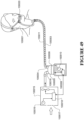
- the present disclosure relates to devices and systems for providing gases to patients for respiratory therapy. More specifically, the present disclosure relates to nasal cannula interfaces for providing gases to patients via the nasal passages.
- Nasal cannula interfaces typically include two nasal prongs that are placed in the patient's nostrils to deliver gases to the patient.
- Nasal cannula assemblies generally consist of entry tubing, either symmetric or single sided that lies across the upper lip. Protruding from this tubing are open ended prongs which extend into the nares of the patient to deliver oxygen. Nasal cannula have the advantage of being more comfortable and acceptable than a face mask to most patients.
- a single flow entry nasal cannula has the advantage of being unobtrusive, and may be more relevant to delivering humidity than a dual flow entry style of nasal cannula, due to the advantage of flow rates and surface area for heat loss.
- a single flow entry however is provided at one side of the cannula, the left or the right side. If the tube is on the left side for example, the user has difficulty in use if the flow source is on the opposite or right side of the user requiring longer lengths of tubing and causing the tube to cross the body.
- the nasal cannula interfaces described herein can advantageously be used to deliver gases to patients over a wide range of concentrations and flow rates.
- the nasal cannula interfaces described herein also include various features designed to improve patient comfort, safety, ease of use, and/or efficiency, reduce costs, and/or provide other benefits.
- a nasal cannula system includes a cannula and a manifold.
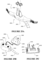
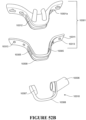
- the cannula includes a central body portion, first and second side portions that extend in opposite lateral directions from the central body portion and contact a cheek of a user when the system is in use, and first and second nasal prongs extending from the central body portion.
- the central body portion includes a patient facing side and at least one retention strap that cooperate to define a cavity.
- the first and second nasal prongs communicate with the cavity.
- the manifold receives a supply of gas from a gas source and includes a gas inlet and a gas outlet.
- the manifold is receivable within the cavity of the cannula such that the gas outlet is aligned with the first and second nasal prongs.
- the at least one retention strap defines first and second lateral edges, and the first and second nasal prongs are located between the first and second lateral edges.
- a nasal cannula system includes a cannula and a supply tube.
- the cannula includes a central body portion, first and second side portions that extend in opposite lateral directions from the central body portion and contact a cheek of a user when the system is in use, and first and second nasal prongs extending from the central body portion.
- the cannula defines a cavity having an inlet at a first end and a second end communicating with first and second gas paths.
- the first and second gas paths communicate with the first and second nasal prongs, respectively.
- the inlet is located at one of the first and second side portions, and the first and second gas paths extend in a lateral direction toward the first and second nasal prongs.
- the supply tube has a first end connectable to a supply of gas from a gas source and a second end coupled to the inlet of the cavity of the cannula.
- a nasal cannula system includes a cannula, a manifold, and a supply tube.
- the cannula includes a central body portion, first and second side portions that extend in opposite lateral directions from the central body portion, and first and second nasal prongs extending from the central body portion.
- the central body portion defines a cavity and a forward-facing inlet to the cavity.
- the first and second nasal prongs communicate with the cavity.
- the manifold receives a supply of gas from a gas source and includes a gas inlet and a gas outlet.
- the manifold is connectable with the cannula such that the gas outlet is aligned with the forward-facing inlet of the cannula and the gas inlet faces a lateral direction.
- the supply tube is connected to the gas inlet of the manifold and positioned forward of the forward-facing inlet of the cannula.
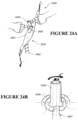
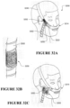
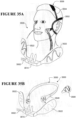
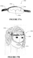
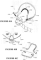
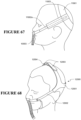
- a nasal cannula patient interface includes first and second nasal prongs, each including an inlet end and an outlet end, and at least one support portion configured to rest upon the nose of a patient at a point at or above the tip of the nose. In use, no portion of the patient interface contacts an upper lip of the patient to provide any substantial support to the patient interface.
- a nasal cannula system comprises a cannula having a central body portion, a first nasal prong and a second nasal prong extending from the central body portion.
- the cannula defines a cavity in communication with the first and second nasal prongs.
- An integrated head strap includes a first section and a second section, wherein the first and second sections extend in opposite lateral directions from the central body portion.
- the first section defines a rear portion of the head strap.
- An adjustable coupling arrangement permits coupling of the first and section sections in an adjustable manner such that a circumference of the head strap is adjustable.
- a supply tube has a first end connectable to a supply of gas from a gas source and a second end coupled to the cavity of the cannula.
- a nasal cannula system includes a cannula comprising a central body portion, a first nasal prong and a second nasal prong extending from the central body portion.
- the cannula defines a cavity in communication with the first and second nasal prongs.
- the cannula defines a lateral slot.
- a head gear strap extends through the lateral slot of the cannula.
- a supply tube has a first end connectable to a supply of gas from a gas source and a second end coupled to the cavity of the cannula.
- a nasal cannula system comprises a cannula comprising a central body portion, a first nasal prong and a second nasal prong extending from the central body portion.
- the cannula defines a cavity in communication with the first and second nasal prongs.
- the cannula defines a first opening at a first location of the cavity and a second opening at a second location of the cavity spaced from the first location.
- a valve body is movable within the cavity.
- a supply tube has a first end connectable to either one of the first opening or the second opening of the cannula and a second end connectable to a supply of gas from a gas source.
- the valve body moves in response to a flow of gas in the cavity from the gas source to block the second opening such that the flow of gas is directed to the first and second nasal prongs and, when the first end of the supply tube is connected to the second opening of the cannula, the valve body moves in response to the flow of gas in the cavity from the gas source to block the first opening such that the flow of gas is directed to the first and second nasal prongs.
- a nasal cannula system comprises a cannula comprising a central body portion, a first nasal prong and a second nasal prong extending from the central body portion.
- the cannula defines a cavity in communication with the first and second nasal prongs.
- the cannula defines a first opening at a first location of the cavity and a second opening at a second location of the cavity spaced from the first location.
- the cannula comprises a first valve that selectively closes the first opening and a second valve that selectively closes the second opening.
- a supply tube has a first end connectable to either one of the first opening or the second opening of the cannula and a second end connectable to a supply of gas from a gas source.
- the second valve blocks the second opening such that a flow of gas from the gas source is directed to the first and second nasal prongs and, when the first end of the supply tube is connected to the second opening of the cannula, the first valve blocks the first opening such that the flow of gas is directed to the first and second nasal prongs.
- a nasal cannula system comprises a cannula comprising a central body portion, a first nasal prong and a second nasal prong extending from the central body portion.
- the cannula defines a cavity in communication with the first and second nasal prongs.
- the cannula defines a first opening at a first end of the cavity and a second opening at a second end of the cavity.
- a supply tube has a first end comprising a first insert and a second end comprising a second insert. Each of the first insert and the second insert is positionable within the cavity to seal the first opening and the second opening and deliver a flow of gas from the gas source to the first and second nasal prongs.
- a nasal cannula system comprises a cannula comprising a central body portion, a first nasal prong and a second nasal prong extending from the central body portion.
- the cannula defines a cavity in communication with the first and second nasal prongs.
- a supply tube has a first end coupled to the cavity of the cannula and a second end connectable to a supply of gas from a gas source.
- the first end of the supply tube defines a connection axis relative to the cannula.
- the supply tube comprises a flexible portion at or adjacent the first end that can be bent at least about 90 degrees to either the left or right side without significant occlusion of an internal passage of the supply tube.
- a nasal cannula system comprises a cannula comprising a cavity and a first nasal prong and a second nasal prong in communication with the cavity.
- a supply tube receives a flow of gas from a gas source.
- the supply tube is connected to the cannula to supply the flow of gas to the cavity of the cannula.
- a clip removably receives the cannula.
- a retention arrangement secures the clip to the head of a patient.
- the cannula is positionable within the clip in a first orientation such that the supply tube extends in a first direction from the clip, and the cannula is positionable within the clip in a second orientation such that the supply tube extends in a second direction from the clip.
- a nasal cannula system comprises a cannula comprising a first nasal prong and a second nasal prong.
- the cannula defines a cavity in communication with the first and second nasal prongs.
- the cannula defines a first opening at a first location of the cavity and a second opening at a second location of the cavity spaced from the first location.
- a supply tube assembly comprises a clip that can be releasably coupled to the cannula in either of a first orientation and a second orientation.
- the supply tube assembly further comprises a supply tube connectable to a supply of gas from a gas source.
- the clip supports the supply tube and comprises a sealing portion.
- the supply tube When the clip is connected to the cannula in the first orientation, the supply tube is connected to the first opening of the cannula and extends in a first direction from the cannula and the sealing portion at least substantially seals the second opening and, when the clip is connected to the cannula in the second orientation, the supply tube is connected to the second opening of the cannula and extends in a second direction from the cannula and the sealing portion at least substantially seals the first opening.
- a nasal cannula system comprises a cannula clip comprising a first nasal prong and a second nasal prong.
- the cannula defines a cavity in communication with the first and second nasal prongs.
- a supply tube assembly comprises a manifold having at least one manifold opening and a supply tube connectable to a supply of gas from a gas source.
- the cannula clip is capable of being releasably coupled to the manifold in either of a first orientation and a second orientation in which the manifold is received within the cavity of the cannula clip and the first and second prongs are aligned with the at least one manifold opening such that a flow of gas is provided to the first and second prongs.
- the supply tube When the cannula clip is connected to the manifold in the first orientation, the supply tube extends in a first direction relative to the first and second prongs and, when the cannula clip is connected to the manifold in the second orientation, the supply tube extends in a second direction relative to the first and second prongs.
- a nasal cannula system comprises a cannula comprising a main body defining a cavity and a first nasal prong and a second nasal prong extending from the main body and in communication with the cavity.
- a supply tube is coupled to the cannula and is in communication with the cavity. The supply tube is connectable to a supply of gas from a gas source to deliver a flow of gas to the cavity and the first and second nasal prongs.
- the first and second nasal prongs are tiltable relative to the main body of the cannula between at least a first position in which the first and second nasal prongs are tilted in a first direction relative to the main body and a second position in which the first and second nasal prongs are tilted in a second direction relative to the main body.
- a first surface of the main body defines a patient-facing surface of the cannula in the first position and a second surface of the main body defines the patient-facing surface of the cannula in the second position to effectively switch the side from which the supply tube extends from the cannula between the first and second positions.
- a nasal cannula system comprises a cannula defining a cavity and comprising a first nasal prong and a second nasal prong extending from the cannula and in communication with the cavity.
- a supply tube is coupled to the cannula and is in communication with the cavity. The supply tube is connectable to a supply of gas from a gas source to deliver a flow of gas to the cavity and the first and second nasal prongs.
- the first and second nasal prongs are directionally-oriented relative to the cannula and are movable between at least a first position in which the first and second nasal prongs are oriented such that openings of the prongs generally face in a first direction relative to the cannula and a second position in which the first and second nasal prongs are oriented such that the openings of the prongs generally face in a second direction relative to the cannula.
- a first surface of the cannula defines a patient-facing surface in the first position and a second surface of the cannula defines the patient-facing surface in the second position to effectively switch the side from which the supply tube extends from the cannula between the first and second positions.
- a nasal cannula system comprises a cannula defining a patient-facing surface and a cavity and comprising a first nasal prong and a second nasal prong extending from the cannula and in communication with the cavity.
- a manifold supports the cannula for rotation about at least one axis between at least a first position and a second position opposite the first position.
- a supply tube is coupled to the manifold and in communication with the cavity. The supply tube is connectable to a supply of gas from a gas source to deliver a flow of gas to the cavity and the first and second nasal prongs.
- the supply tube When the cannula is in the first position, the supply tube is positioned on a first side of the first and second nasal prongs and, when the cannula is in the second position, the supply tube is positioned on a second side of the first and second nasal prongs to effectively switch the side from which the supply tube extends from the cannula between the first and second positions.
- a nasal cannula system comprises a cannula defining a cavity and comprising a first nasal prong and a second nasal prong extending from the cannula and in communication with the cavity.
- a supply tube is coupled to the cannula and is in communication with the cavity. The supply tube is connectable to a supply of gas from a gas source to deliver a flow of gas to the cavity and the first and second nasal prongs.
- a pressure line is in communication with the cavity and is configured to be connectable to a control unit of the gas source or a display unit to provide a signal to the control unit or display unit indicative of a pressure within the cavity.
- a nasal cannula comprises a cannula body defining a cavity and comprising a first nasal prong and a second nasal prong extending from the cannula and in communication with the cavity.
- the cannula defines a patient-facing surface having one or more comfort features selected from a plurality of through-holes, a plurality of raised bumps, a plurality of grooves and a gel pad.
- a nasal cannula comprises a cannula body defining a cavity and comprising a first nasal prong and a second nasal prong extending from the cannula and in communication with the cavity.
- the cannula body comprises a central portion containing the first and second nasal prongs and first and second side portions extending from each side of the central portion.
- the cannula body defines a patient-facing surface.
- the central portion is spaced forwardly of adjacent portions of the first and second side portions such that, in use, the patient-facing surface of the central portion is spaced from the upper lip of the patient.
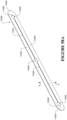
- a supply tube for a nasal cannula comprises a tube body having a first end a second end.
- the tube body comprises a malleable section that permits the section to be shaped by an external force and that substantially retains the shape after the external force is removed.
- a nasal cannula system comprises a cannula defining a cavity and comprising a first nasal prong and a second nasal prong extending from the cannula and in communication with the cavity.
- a supply tube is coupled to the cannula and is in communication with the cavity.
- the supply tube is connectable to a supply of gas from a gas source to deliver a flow of gas to the cavity and the first and second nasal prongs.
- a support arrangement supports the supply tube at a spaced location from the cannula.
- the support arrangement comprises a fastener having a first portion coupled to the supply tube and a second portion located at the spaced location.
- a nasal cannula system comprises a cannula defining a cavity and comprising a first nasal prong and a second nasal prong extending from the cannula and in communication with the cavity.
- a supply tube is coupled to the cannula and is in communication with the cavity.
- the supply tube is connectable to a supply of gas from a gas source to deliver a flow of gas to the cavity and the first and second nasal prongs.
- a retention arrangement secures the cannula to the patient.
- a support arrangement supports the supply tube at a spaced location from the cannula, which is located on the retention arrangement.
- a nasal cannula system comprises a cannula defining a cavity and comprising a first nasal prong and a second nasal prong extending from the cannula and in communication with the cavity.
- a supply tube is coupled to the cannula and is in communication with the cavity.
- the supply tube is connectable to a supply of gas from a gas source to deliver a flow of gas to the cavity and the first and second nasal prongs.
- a support arrangement supports the supply tube at a spaced location from the cannula.
- the support arrangement comprises a fastener that engages a piece of fabric at the spaced location.
- a nasal cannula system comprises a cannula defining a cavity and comprising a first nasal prong and a second nasal prong extending from the cannula and in communication with the cavity.
- a supply tube is coupled to the cannula and is in communication with the cavity.
- the supply tube is connectable to a supply of gas from a gas source to deliver a flow of gas to the cavity and the first and second nasal prongs.
- a support arrangement supports the supply tube at a spaced location from the cannula.
- the support arrangement comprises at least one of an armband that engages the supply tube, an adhesive pad comprising a fastener for releasably fastening the supply tube to the adhesive pad, a generally U-shaped support that sits on the patient's shoulder and engages the supply tube, and a headgear strap comprising a strap extending over the top of the patient's head and engages the supply tube.
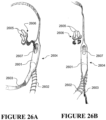
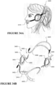
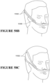
- a retention arrangement for a nasal cannula assembly comprises a headgear strap comprising a first ear loop and a second ear loop, each of which at least partially surround an ear of the patient.
- a connection portion connects the retention arrangement to the nasal cannula assembly.
- a strap portion extends around the back of the patient's head between the first and second ear loops.
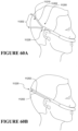
- a retention arrangement for a nasal cannula comprises a headgear strap comprising a strap portion.
- a connection portion connects the retention arrangement to the nasal cannula.
- the strap portion extends around the patient's head and extends from the first and second pads at an angle relative to the nasal cannula.
- a retention arrangement for a nasal cannula comprises a frame comprising a connection portion that connects the retention arrangement to the nasal cannula.
- a first ear stem portion and a second ear stem portion extend rearwardly from opposite sides of the connection portion.
- the ear stem portions are configured to be positioned above the ears of the patient.
- a nasal cannula system comprises a cannula having a central portion defining a cavity and comprising a first nasal prong and a second nasal prong extending from the central portion and in communication with the cavity.
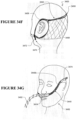
- a first side portion and a second side portion extend in a lateral direction from opposing sides of the central portion.
- a supply tube is coupled to the cannula and is in communication with the cavity. The supply tube is connectable to a supply of gas from a gas source to deliver a flow of gas to the cavity and the first and second nasal prongs.
- a first adhesive pad and a second adhesive pad are configured to be adhesively secured to the face of the patient and connectable to a respective one of the first and second side portions of the cannula through an adjustable fastening arrangement.
- a nasal cannula system comprises a cannula defining a cavity and comprising a first nasal prong and a second nasal prong extending from the cannula and in communication with the cavity.
- a modular retention arrangement secures the cannula to the patient.
- the cannula is configured to be used with any one of the retention arrangements selected from a set of adhesive pads that attach to the patient's face, a headgear strap and a halo-style headgear strap that has a strap portion extending over the top of the patient's head.
- a nasal cannula system comprises a cannula defining a cavity and comprising a first nasal prong and a second nasal prong extending from the cannula and in communication with the cavity.
- a modular retention arrangement secures the cannula to the patient.
- the retention arrangement comprises a nose strip coupled to the cannula and attachable to the nose of a patient and a headgear strap comprising a clip configured to receive the cannula.
- the cannula can be secured to the patient using either the nose strip or the headgear strap.
- a retention arrangement for a nasal cannula comprises a headgear strap that is connectable to a nasal cannula and capable of being tensioned around the head of a patient.
- the headgear strap comprises a tension indicator that provides a first indication when the tension is at an incorrect value and a second indication when the tension is at a correct value.
- a retention arrangement for a nasal cannula comprises a headgear strap that is connectable to a nasal cannula. At least one strap extends around the head of a patient from one side to the other of the cannula. A tension adjuster tensions the headgear strap by varying an effective length of the at least one strap by winding up a portion of the at least one strap.
- a headgear strap for a nasal cannula comprises a first portion that is connectable to a nasal cannula and a second, elastic portion that is positioned at a back of a head of a patient in use.
- a pad extends at least partially along the second, elastic portion.
- a nasal cannula assembly comprises a cannula defining a cavity and comprising a first nasal prong and a second nasal prong extending from the cannula and in communication with the cavity.
- a head strap is positioned around the head and above the ears of the patient in use.
- a first arm is coupled to a first side of the cannula and a second arm is coupled to a second side of the cannula. Upper end portions of each of the first and second arms are attached to the head strap.
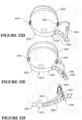
- a nasal cannula system comprises a cannula defining an open cavity and comprises a first nasal prong and a second nasal prong extending from the cannula and in communication with the cavity.
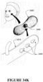
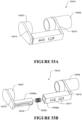
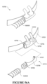
- a manifold is configured to be removably coupled to the cannula and a portion of the manifold received into the cavity of the cannula.
- the manifold includes first and second holes that align with the first and second nasal prongs when the manifold is coupled to the cannula, and the manifold also includes a side opening configured to be coupled to a tube.
- An inner surface of the cavity of the cannula includes a first attachment portion and an outer surface of the portion of the manifold includes a second attachment portion. The first and second attachment portions can be configured to engage one another to secure the manifold to the cannula.
- the first and second attachment portions comprise cooperating portions of a hook and loop material fastener.
- the nasal cannula system can also include an arrangement in which the cavity and the portion of the manifold have corresponding symmetrical shapes so that the portion of the outer surface of the manifold can be positioned within the cavity in multiple orientations.
- the cavity and the portion of the manifold are circular or oval shaped.
- the first and second attachment portions are substantially planar.
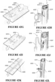
- a nasal cannula assembly comprises a cannula defining a cavity and a first nasal prong and a second nasal prong extending from the cannula and in communication with the cavity.
- the cannula includes a first outer surface and a second outer surface that are substantially planar and extending along the length of the cannula.
- the cannula also includes a first end and a second end.
- a retention arrangement is coupled to the cannula and configured to support the cannula on the face of a patient.
- a tube can be coupled to the cannula adjacent either the first end or the second end of the cannula and configured to be in communication with the cavity.
- the cannula has a first position in which the first outer surface contacts the face of the patient and the first and second nasal prongs extend into the nostrils of the patient.
- the cannula has a second position in which the second outer surface contacts the face of a patient and the first and second nasal prongs extend into the nostrils of the patient.
- the cannula has a substantially triangular cross-sectional shape.
- the nasal cannula assembly can be arranged so that an angle between the first and second nasal prongs and the first outer surface is substantially the same as an angle between the first and second nasal prongs and the second outer surface.
- the first and second nasal prongs extend outward from the cannula at a corner of the substantially triangular cross-sectional shape between the first and second outer surfaces.
- a nasal cannula assembly comprises a cannula body defining a cavity and comprises a first nasal prong and a second nasal prong extending from the cannula and in communication with the cavity.
- the first and second nasal prongs can have a relaxed position in the absence of any substantial external force.
- An outer portion is configured to be movably coupled to the cannula body and configured to surround at least a portion of the cannula body.
- the outer portion defines at least one opening through which the first nasal prong extends and the outer portion includes at least one edge defining the at least one opening.
- the outer portion can move relative to the cannula body and the first and second nasal prongs, and the at least one edge is configured to engage the first and second prongs and deflect the first and second prongs from their relaxed positions.
- the cannula body and the outer portion are substantially cylindrical and the outer portion extends around the circumference of the cannula body, and the outer portion can be rotated about the cannula body.
- Each of the first and second nasal prongs can include a flexible base portion configured to allow the angle at which the prong extends from the cannula body to change.
- the at least one opening can comprise a first opening and a second opening and the at least one edge can comprise a first edge and a second edge, the first opening defining the first edge and the second opening defining the second edge.
- the first nasal prong can extend through the first opening and the second nasal prong extends through the second opening.
- the outer portion includes a slot and the cannula body includes a protrusion that extends into the slot.
- the protrusion can be configured to move within the slot and the slot can have side walls configured to engage the protrusion and limit the amount of movement of the outer portion relative to the cannula body.
- a nasal cannula system comprises a cannula defining a cavity and comprises at least one nasal prong extending from the cannula and in communication with the cavity.
- a frame portion is configured to support the cannula and at least one head strap is coupled to the frame portion and positioned around the head of the patient in use.
- the cannula is slidably supported by the frame portion and can move relative to the frame portion, the cannula including an opening through which the frame portion extends.
- the cannula system can comprise a tube support member supported by the frame portion or the head strap and the tube support member can be configured to support and selectively release a tube.
- the tube support member is configured to loosely support the tube so that the tube can slide within the support member.
- the tube support member can comprise a strap configured to wrap around a tube and a clip configured to couple the strap to the head strap or frame portion.
- the frame portion can have a circular or rounded cross-section and the cannula can move laterally relative to the frame portion and can rotate relative to the frame portion.
- the interface between the cannula and the frame portion is a friction fit that allows the cannula to retain its position relative to the frame portion when not being moved by a user.
- the frame portion can include a plurality of notches configured to interact with the cannula and provide discrete locations along the frame portion at which the cannula can be supported.
- a nasal cannula system comprises a cannula defining a cavity and comprises a first nasal prong and a second nasal prong extending from the cannula and in communication with the cavity.
- the cannula includes an opening extending through a portion of the cannula and a head strap is positioned around the head of the patient in use.
- the opening on the cannula is configured to receive the head strap so that the head strap extends through the opening and supports the cannula and the cannula is configured to slide relative to the head strap and change positions along the head strap.
- the cannula comprises a planar outer surface configured to contact the face of a patient when the first and second prongs are inserted into the nostrils of a patient.
- the head strap can be made of an elastic material and configured to hold the cannula against the face of a patient.
- a nasal cannula system comprises a cannula defining a cavity and comprising at least one nasal prong extending from the cannula and in communication with the cavity.
- the cannula includes a first slot and a second slot.
- a first frame portion is configured to be slidably received by the first slot of the cannula and a second frame portion is configured to be slidably received by the second slot.
- At least one head strap is coupled to the first and second frame portions and positioned around the head of the patient in use.
- the cannula is slidably supported by the first and second frame portions and can be selectively moved relative to the first and second frame portions.
- the cannula includes a side opening configured to receive a supply tube, and the first and second frame portions are configured to allow a tube to pass between them.
- a nasal cannula system can also comprise a tube support member supported by the first and second frame portions and configured to slide relative to the first and second frame portions to position the supply tube relative to the first and second frame portions.
- the first and second frame portions can have circular cross-sections and the first and second slots can be configured to retain the first and second frame portions.
- the first frame portion is positioned above the second frame portion and the first and second slots are located on the outer side of the cannula facing away from the patient.
- the cannula can include a planar surface facing the face of the patient.
- a nasal cannula system comprises a cannula defining a cavity and comprising at least one nasal prong extending from the cannula and in communication with the cavity.
- the cannula includes a slot and a first frame portion is configured to be slidably received by the slot of the cannula.
- a second frame portion is fixedly coupled to the cannula.
- a first dial and a second dial are each coupled to both the first frame portion and the second frame portion.
- At least one head strap is coupled to the first and second frame portions and positioned around the head of the patient in use.
- the cannula is slidably supported by the first frame portion and the dials can be configured to rotate to move a section of the second frame portion and the cannula relative to the first frame portion.
- the first and second frame portions can be wires coated with a soft material.
- the second frame portion is located above the first frame portion when the cannula system is worn by a patient.
- a retention arrangement for a nasal cannula comprises a band configured to extend around the head of a patient and a first arm pivotally coupled to the band at a first joint.
- a second arm is pivotally coupled to the first arm at a second joint and the second arm can be connectable to a nasal cannula at a third joint.
- the first, second and third joints are configured to allow three dimensional movement and are configured to retain the relative position of the band, first arm, second arm, and cannula unless moved by a user.
- the band includes a stabilizing portion that is wider than the band and configured to contact the head of a patient.
- the third joint can be coupled to the side of a cannula.
- the first, second and third joints are ball joints.
- a nasal cannula system comprises a cannula defining a cavity and comprises at least one nasal prong extending from the cannula and in communication with the cavity.
- the cannula includes a slot and has a clip portion extending from the cannula.
- a frame is configured to support the cannula and be coupled to a head strap.
- the frame includes an opening configured to receive the clip portion of the cannula and the clip portion can be movable within the opening so that the cannula can assume different positions relative to the frame while being supported by the frame.
- the cannula is positioned between the frame and the face of a patient when in use.
- the frame can include at least one pad member arranged to contact the face of a patient when in use.
- the interface between the clip portion and the frame opening allows the cannula to be moved laterally and rotated relative to the frame.
- a cannula system can also include a head strap coupled to the frame and a tube support member supported by the head strap or frame.
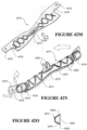
- a nasal cannula system comprises a cannula defining a cavity and comprises at least one nasal prong extending from the cannula and in communication with the cavity.
- the cannula has a first end portion and a second end portion.
- a first corrugated tube section is coupled to the first end portion of the cannula and a second corrugated tube section is coupled to the second end portion of the cannula.
- the position of the cannula relative to a patient's face can be adjusted by expanding and compressing the first and second corrugated tube sections.
- the cannula system also comprises a first non-corrugated tube coupled to the first corrugated tube section and a second non-corrugated tube coupled to the second corrugated tube section.
- the first and second corrugated tube sections can be backed by a head strap.
- a prong arrangement for a nasal cannula comprises a prong comprising a first prong portion comprising a first slot and a second prong portion comprising a first flange.
- the second prong portion is coupled to the first prong portion and the first flange extends longitudinally within the first slot.
- the first and second prong portions are configured to extend away from a cannula and define a passageway and the first flange is movable within the first slot so that the first prong portion and second prong portion can be moved toward and away from one another to adjust an outer dimension of the prong.
- the first and second prong portions each include a sealing member adjacent the cannula and the sealing members overlap each other and are configured to slide relative to one another.
- the prong can further comprise a size indicator configured to indicate the relative outer dimensions of the prong.
- the prong includes a second slot and a second flange, the second flange extending longitudinally within the second slot.
- the first slot can comprises two side walls configured to limit the extent to which the first flange can move within the first slot.
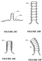
- a prong arrangement for a nasal cannula comprises a prong comprising a first collapsible portion configured to be coupled to a cannula.
- the first collapsible portion includes a first passageway.
- a second collapsible portion is coupled to the first collapsible portion and has a second passageway.
- a third collapsible portion is coupled to the second collapsible portion and has a third passageway.
- the first, second and third collapsible portions are configured to collapse and expand telescopically relative to one another so that the height of the prong can be adjusted.
- the third collapsible portion includes a top edge that is configured to form a seal with a patient's nostril.
- the outer dimensions of the third collapsible portion can be larger than the outer dimensions of the second collapsible portion, and the outer dimensions of the second collapsible portion can be larger than the outer dimensions of the first collapsible portion.
- the first, second and third passageways can be coaxial.
- a prong arrangement for a nasal cannula comprises a cannula defining a cavity and the cannula includes a slot.
- a first prong extends from the cannula and is fixed relative to the cannula.
- a second prong extends from the cannula through the slot and is movable relative to the cannula. The second prong can be moved within the slot in order to adjust a distance between the first prong and the second prong.
- the second prong includes a pin and the slot includes multiple notches, and the notches are configured to receive the pin when the second prong is moved to discrete locations within the slot.
- the second prong can include a rib that extends from the base of the prong and the slot can include multiple grooves configured to receive the rib.
- the second prong includes a tab having multiple notches that are configured to engage an edge of the slot so that the second prong can be held in multiple discrete positions relative to the slot.
- a prong for a nasal cannula comprises a film having a substantially cylindrical shape and a plurality of ribs coupled to the film around the circumference of the film.
- the film and ribs expand outward as gas flow increases through the prong, and the outer diameter of the prong increases to form a seal with a patient's nostril.
- the ribs are substantially fixed and do not bend or move relative to one another.
- a nasal cannula system comprises a cannula defining a cavity and comprises at least one nasal prong extending from the cannula and in communication with the cavity.
- a support member is coupled to the cannula and configured to support the cannula.
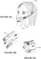
- the support member is configured to extend upward from the cannula and around a patient's nose when in use.
- the support member contacts a portion above a tip of the patient's nose and the support member comprises a bendable material that can be shaped to correspond to the shape of the face of a patient.
- a nasal cannula system also includes a head strap configured to wrap around the head of a patient and the head strap is removably coupled at one end to the support member and adjustably coupled to the support member at the other end.
- the bendable material is a metal material and is located at the upper portion of the support member.
- the support member can include an attachment portion having multiple notches and the cannula can include an opening configured to receive the attachment portion. The notches can be configured to interact with the opening to couple the support member to the cannula and allow for adjustment of the support member relative to the cannula.
- the cannula includes a first tube extending from one side of the cannula and a second tube extending from the other side of the cannula, and the support member is coupled to the first and second tubes of the cannula.
- the first tube can be supported by a first padded member and the second tube can be supported by a second padded member, and the first and second padded members can be configured to rest against a patient's face.
- a nasal cannula system also includes a head strap coupled to the first and second padded members and configured to extend around the head of a patient. The first tube and the second tube can be removable from the cannula so that the cannula can be removed and rotated relative to the rest of the system.
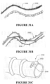
- a tube arrangement for a nasal cannula system comprises a cannula tube comprising an outer wall and an opening.
- the tube includes a longitudinal axis and the outer wall comprises a thin material that has been folded or rolled and sealed at an edge.
- the outer wall is made of a fabric that provides insulation.
- Embodiments of a tube arrangement can also include a spring extending within the outer wall.
- the cannula tube can also be coupled to a connector at its opening and the connector can include a valve.
- the cannula tube further comprises an extruded tube extending within the outer wall.
- the outer wall can include a tab having one or more holes configured to be coupled to a head strap.
- the outer wall is made of an insulating material, a spring extends within the outer wall, and a breathing tube extends within the spring.
- the outer wall is made of an insulating material
- a breathing tube extends within the outer wall
- a spring extends within the breathing tube
- at least a pressure line tube extends within the outer wall in addition to the breathing tube.
- Some embodiments can also include a breathing tube within the outer wall, the breathing tube having a cannula portion from which at least one prong extends, the cannula tube being flexible so that it can curve around the face of a patient.
- Each end of the cannula tube can include a tab with holes configured to receive a pin located on a head strap.
- Each end of the cannula tube can include a connector configured to receive an inspiratory tube connector, each connector including a valve.
- the outer wall is made of a breathable material.
- a tube arrangement for a nasal cannula system comprises a tube comprising an outer wall and an opening.
- the tube includes a longitudinal axis and the outer wall comprises a thin material that has been folded or rolled, and the outer wall includes one or more cut portions that extend through the material.
- the one or more cut portions comprise a tab that can be pulled away from the tube, and the tab is configured to engage a support device in order to hang the tube.
- the tab includes a hole configured to receive a hook or hanger.
- the cut portions can comprise slots defining a portion of the material that can be pulled away from the tube while remaining connected at two sides, and the pulled away material can form a hook portion that can engage a hanger.
- the cut portions can comprise two tabs that can be pulled away from the tube, the ends of the tabs being configured to be coupled together or to another structure.
- the tube can also comprise an inner tube and a spring within the inner tube.
- a cannula tube arrangement for a nasal cannula system comprises a tube comprising an outer wall and the outer wall comprises a thin film having a first edge and a second edge. The film is folded or rolled and the first and second edges are sealed together. A bead is located on the outer wall and configured to provide structural support to the tube.
- the bead includes a cannula portion configured to receive a cannula with prongs, and the cannula portion includes two holes that extend through the film.
- the tube can include a first end and a second end, and the first end and second end can be coupled to connectors having valves.
- the first and second ends can each include a tab having a hole configured to be coupled to a head strap.
- the first and second edges of the film are heat-sealed to form the tube.
- the bead can be printed or extruded onto the outer wall.
- the bead can have a pattern that is configured to create bend areas along the tube length.
- the bead is on the inside of the tube.
- the bead can comprise thermal and structural elements printed on the film.
- the first edge overlaps the second edge and the first and second edges can extend into the tube.
- a cannula tube arrangement for a nasal cannula system comprises a tube comprising an outer wall.
- the outer wall comprises a thin plastic film having a first edge and a second edge.
- a substantially planar side wall is coupled to the outer wall and a bead is located on the other wall and configured to provide structural support to the tube.
- the first edge is coupled to the side wall and the second edge is also coupled to the side wall so that a cavity exists between the outer wall and the side wall.
- the first edge and second edge are heat-sealed to the side wall, and the side wall is made of a fabric material.
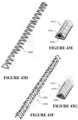
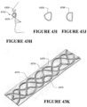
- a cannula tube arrangement comprises a spring having a length and a cross-section having at least one substantially planar side.
- a tube surrounds the spring and the tube defines a passageway through which gas can pass.
- At least one nasal prong is coupled to the tube and communicates with the passageway.
- the spring has a V-shaped or triangular cross-section.
- the spring can comprise a thin folded sheet of metal having cut-out portions along the length of the spring.
- the spring can include a middle section and first and second ends, and the cross-section of the middle section can be smaller than the cross-section at the first and second ends.
- the spring is a helical spring having a triangular cross-section.
- the spring can be a helical wire having bent ends that extend in the direction of a third side.
- the spring can also have a substantially triangular cross-section with curved sides.
- the spring has a cross-section shaped like a half-circle.
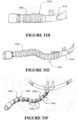
- a cannula breathing tube arrangement comprises a tube made at least in part from a foam material.
- the tube has a length and a substantially planar side extending along the length of the tube and the tube defines a passageway.
- a spring extends through the passageway of the tube and along the length of the tube, and the spring is configured to impede kinking of the tube.
- the tube includes a cavity extending along the length of the tube and a shapeable rod extending through the cavity.
- the foam material is a closed cell foam material.
- the tube can include a slot extending along the length of the tube, the slot being configured to receive a coupling member.
- the coupling member is a mushroom head member configured to slide into the slot.
- a cannula tube arrangement comprises a tube having a length and a substantially planar side extending along the length of the tube.
- the tube defines a passageway and has an inner surface.
- the tube includes at least one rib located on the inner surface and extending along the length of the tube, and the at least one rib is configured to provide structural support and impede kinking of the tube.
- the at least one rib comprises multiple ribs on the inner surface.
- the tube can comprise a rectangular cross-section and include a fabric material surrounding the tube.
- the tube has a substantially triangular cross-section and in other embodiments, the tube has a substantially half-circle cross-section.
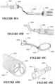
- a cannula tube arrangement comprises a cannula tube defining a passageway and having an end.
- a connector is coupled to the end of the cannula tube and a supply tube is configured to be coupled to the connector of the cannula tube.
- a wire configured to transfer heat extends out of the supply tube.
- the cannula tube is configured to receive the wire into the passageway, and the wire is configured to transfer heat into the cannula tube.
- the wire is insulated and bendable so that it can conform to the shape of the cannula tube.
- the wire can be rigid enough to support the cannula tube.
- a cannula and tube arrangement comprises a cannula tube having a length and defining a passageway.
- a heating element extends along the length of the cannula tube and is configured to transfer heat to gas passing through the cannula tube.
- a cannula comprising at least one nasal prong and is coupled to the cannula tube.
- the heating element is a coiled wire that extends within the cannula tube.
- the cannula tube can include an end and an electrical connector coupled to the end of the cannula tube.
- the electrical connector is also a tube connector configured to attach a second tube to the cannula tube.
- the heating element can be surrounded by a thin film.
- the heating element comprises two wires coupled to a conductive polymer, and the two wires are configured so that a voltage can be applied through the polymer to generate heat.
- the heating element is configured to provide structural support to the cannula tube.
- the heating element is wrapped around the outer surface of the cannula tube.
- the heating element comprises a film having a conductive strip, the film is wrapped around the cannula tube, and the conductive strip is configured to generate heat when a current is passed therethrough.
- the heating element can be made from positive temperature coefficient material configured so that its resistance increases with temperature so that a constant voltage power supply can be used to power the heating element.
- the cannula tube is made of a flexible and light material, the cannula tube is coupled to a connector, the connector is coupled to a tube that is less flexible and heavier than the cannula tube, and the heating element extends along substantially the entire length of the cannula tube and the tube.
- the connector can include an opening configured to receive a temperature sensor and the cannula tube can be configured to be removably attached to the cannula.
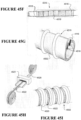
- a cannula tube arrangement comprises a cannula tube having a length and defining a first passageway.
- the cannula tube has an outer surface and a spiral tube is wrapped around the outer surface of the cannula tube.
- the spiral tube defines a second passageway and has an inner wall adjacent the cannula tube and an outer wall facing away from the cannula tube.
- a first opening extends through the cannula tube and through the inner wall of the spiral tube so that gas flowing inside the cannula tube can enter the spiral tube through the first opening.
- the spiral tube includes a second opening extending through the outer wall of the spiral tube so that gas flowing in the spiral tube can escape into the surrounding environment.
- the second opening is positioned at an opposite end of the cannula tube from the first opening.
- a cannula tube arrangement comprises a cannula tube having a length and defining a passageway.
- the cannula tube has an outer portion and the outer portion comprises a textile material and a heating element knitted or woven into the textile material.
- the heating element is configured to transfer heat to a gas passing through the passageway.
- the heating element is a wire configured to generate heat when electrical current is passed therethrough.
- the heating element is made of a semi-rigid material that provides structural support to the cannula tube.
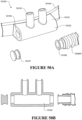
- a manifold for a cannula assembly comprises a manifold body comprising a connector portion having an inlet opening and being configured to receive a tube.
- the manifold also includes a port configured to assist in measuring the pressure of the gas flow and an outlet portion configured to be in communication with the port and configured to be coupled to a pressure sensor.
- the port is a static pressure port positioned on an inner wall of the manifold that is substantially parallel to the bulk flow direction of the gas within the manifold.
- the port is a total pressure port that is directed towards the bulk flow direction and is configured to measure a combination of the static and dynamic pressure.
- the port includes a shroud and is directed towards the bulk flow direction.
- a nasal cannula assembly comprises a cannula defining a cavity and comprising a first nasal prong and a second nasal prong extending from the cannula and in communication with the cavity.
- the cannula also includes an opening.
- a valve is supported within the opening and configured to form a seal when nothing is inserted therethrough.
- the cannula and valve are configured so that a tube can extend through the valve, into the cavity, and through the second nasal prong.
- the valve is a located substantially below the second prong.
- the valve in can be configured to form a seal around a tube extending therethrough.
- the valve is a duck bill valve.
- Embodiments of a nasal cannula assembly can further comprise a removable cover coupled to the outer surface of the cannula and covering the opening.
- the cannula can also include two openings and two corresponding valves where each of the valves is configured to receive either a cannula tube or a nasogastric tube.
- the cannula includes a first side and a second side, and one of the valves is located on each of the first and second sides.
- the second prong is removable from the cannula.
- a nasal cannula assembly comprises a cannula defining a cavity and comprising a first nasal prong extending from the cannula and in communication with the cavity.
- the cannula includes a first groove and the first prong includes a second groove.
- the first groove is aligned with the second groove so that a portion of a tube can extend through the first and second grooves and is directed into a nostril of a patient.
- the first and second grooves are configured to accommodate a nasogastric tube.
- the first prong can include an outer surface and the second groove can be located on the outer surface of the first prong and can extend longitudinally relative to the first prong.
- the cannula includes a second prong and a third groove, the second prong includes a fourth groove, and the third and fourth grooves are aligned so that a portion of a tube can extend through the third and fourth grooves and is directed into a nostril of a patient.
- a nasal cannula comprises a nasal prong having an outer wall and an end.
- the outer wall includes a cut portion defining a flap that can be pushed into the prong to form an opening in the outer wall of the prong.
- the opening is configured to receive a tube so that the tube can extend through the opening and out of the end of the prong.
- the outer wall defines a passageway
- the flap is configured to block the passageway when a tube is inserted through the opening.
- the flap is configured to align with and form at least a substantial seal with the outer wall when a tube is not inserted through the opening.
- the prong can also include a slit that extends from the cut portion to the end of the prong, the slit being configured to allow a tube to selectively pass through the slit.
- a nasal cannula assembly comprises a cannula defining a cavity and comprising a first nasal prong extending from the cannula and in communication with the cavity.
- the cannula includes an opening and a valve supported within the opening.
- An inner member is supported within the cavity and movable relative to the cannula.
- the inner member includes a hole configured to receive a tube. The opening is positioned substantially below the first nasal prong and the inner member can be moved so that the hole is aligned with the valve so that a tube can extend through the valve and the hole and into the first prong.
- the cannula includes a second opening having a second valve positioned substantially below a second nasal prong, and the inner member includes a second hole that can be aligned with the second valve and second prong.
- the inner member is substantially cylindrical and is configured to be coupled to a supply tube. The valve can be configured to form a seal when nothing is extended therethrough.
- nasal cannula assembly comprises a cannula body having a first slot and a second slot.
- the assembly also includes a first sliding portion having a first prong coupled to a first tube and a second sliding portion having a second prong coupled to a second tube.
- a portion of the first sliding portion is configured to slide within the first slot and a portion of the second sliding portion is configured to slide within the second slot.
- the first and second prongs are movable relative to the cannula body so that each of the first and second prongs can be adjusted relative to the cannula body.
- the first slot and the second slot extend substantially horizontally and are positioned side by side on the cannula body.
- a nasal cannula assembly comprises a cannula defining a cavity and comprising a first nasal prong extending from the cannula and in communication with the cavity.
- the assembly also includes a slider member that engages an outer surface of the cannula, and the slider member is configured to move relative to the cannula.
- the slider member is configured to selectively move along the outer surface of the cannula and over the first nasal prong.
- the slider member includes a groove configured to receive a portion of a tube.
- the first nasal prong is flexible and can fold under the slider member when the slider member is moved to cover the first nasal prong.
- a nasal cannula assembly comprises a cannula defining a cavity and comprising a single nasal prong extending from the cannula and in communication with the cavity.
- the assembly also includes a strap configured to support the prong and engage the face of a patient.
- the strap includes an adhesive material configured to selectively couple the strap to a patient's face.
- the strap includes an opening through which the prong extends and the strap is configured to extend from under the patient's nose upward along the sides of the patient's nose.
- the strap includes at least one slot configured to receive a tube.
- the strap includes holes positioned to align with a nostril of a patient when the strap is in use.
- the prong can include corrugations configured to allow the prong to bend and change shape.
- the prong includes a tapered base portion that is configured to form a seal with a patient's nostril.
- the cannula is coupled to a tube and the tube includes a support member configured to support the tube and be selectively coupled to the face of a patient.
- the support member can also include a support portion configured to receive and support a nasogastric or other tube.
- Embodiments of the cannula assembly can further comprise a cheek pad configured to adhere to a patient's cheek and be selectively coupled to the support member.
- the prong includes a tapered base portion that is narrower toward the top and wider toward the bottom, and the prong includes a recess below the tapered portion and the recess is configured to retain the portion of the strap adjacent the opening.
- a nasal cannula assembly comprises a cannula defining a cavity and comprising a single nasal prong extending from the cannula and in communication with the cavity.
- the assembly also includes a frame having a bridge portion that extends away from the face of a patient and creates a space between the bridge portion and the patient's face.
- the bridge portion is configured to support the cannula, and the bridge portion including a slot and a portion of the cannula can move within the slot.
- a tube is coupled to the cannula and extends from a bottom portion of the cannula. The tube is configured to extend from under the cannula and bend upward so that it extends over the frame.
- the cannula is supported by the frame and positioned substantially within the space between the bridge portion and the patient's face when the cannula assembly is in use.
- the bridge portion of the frame includes cut out portions configured to receive a portion of the tube.
- the cannula includes a grip portion that extends through the slot.
- the frame can include a pad configured to contact the face of a patient when in use.
- the frame includes one or more openings configured to receive a head strap.
- the bridge portion includes a tubing arm that at least partially defines a tubing recess through which the tube can extend.
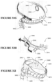
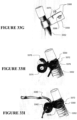
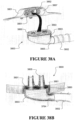
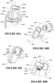
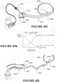
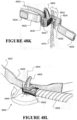
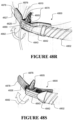
- a nasal cannula assembly comprises a cannula frame having an upper extension portion, and the upper extension portion having a single prong and a prong opening in communication with the prong.
- the assembly also includes a retainer portion coupled to the extension portion and having a retainer opening aligned with the prong opening.
- the assembly also includes a manifold pivotally coupled to the retainer portion, and the manifold has a manifold opening aligned with the retainer opening and the prong opening.
- the manifold is configured to pivot relative to the cannula frame about the axis of the manifold opening, and gas can pass through the manifold and into the prong.
- the cannula frame includes a lower extension portion and the retainer portion includes a lower portion that engages a bottom portion of the manifold.
- the bottom portion of the manifold includes a pin and the lower portion of the retainer portion includes a hinge recess, and the pin is configured to be received within the hinge recess, and the manifold configured to pivot about the pin.
- the manifold is configured to rotate about 180 degrees relative to the cannula frame so that tubing coupled to the manifold can exit in an opposite direction.
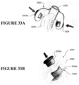
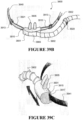
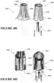
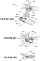
- a nasal cannula assembly comprises a cannula frame having an upper extension portion.
- the upper extension portion has a single prong and a prong opening in communication with the prong.
- the upper extension portion also has a bottom side.
- the assembly includes a tube rotatably coupled to the bottom side of the upper extension portion and in communication with the prong so that gas can pass from the tube through the prong opening and into the prong.
- the tube is configured to bend and rotate relative to the cannula frame.
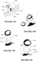
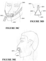
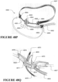
- a nasal cannula assembly comprises a cannula defining a cavity and comprising a single nasal prong extending from the cannula and in communication with the cavity.
- the assembly comprises a cable configured to slidably support the cannula and a tube coupled to the cannula and configured to provide gas to the cavity. The position of the cannula can be adjusted by sliding the cannula along the cable.
- the tube is tapered so that its cross-section is narrower closer to the cannula.
- Some embodiments further comprise an attachment portion coupled to the cable and configured to receive a portion of the tube.
- the tube includes an attachment member that is configured to engage and be coupled to the attachment portion.
- the cable can include indent portions configured to retain the cannula in a selected position.
- a nasal cannula assembly comprises a cannula frame having a bridge portion that extends away from the face of a patient and creates a space between the bridge portion and the patient's face.
- the bridge portion supports a single nasal prong.
- the assembly includes a first tube coupled to the prong and extending downward from the prong.
- the cannula frame defines a recess through which a second tube can extend between the bridge portion and a patient's face when in use.
- the bridge portion includes a cut-out portion configured to receive a portion of the first tube, causing the tube to bend and extend away from the assembly to the side of a patient.
- the cannula frame includes a contact portion that is configured to contact the face of a patient and comprises a soft material.
- a nasal cannula assembly comprises a cannula defining a cavity and comprising a single nasal prong extending from the cannula and in communication with the cavity.
- the cannula has a cannula opening in communication with the cavity and the opening has an axis.
- the assembly also includes a manifold pivotally coupled to the cannula and configured to pivot about the axis of the cannula opening.
- the assembly also includes a tube coupled to the manifold and configured to supply gas to the manifold.
- the manifold includes a manifold opening aligned with the cannula opening and in communication with the cavity.
- the cannula includes frame portions extending outward from the cannula, the frame portions form one or more recesses between the cannula and the face of a patient when in use, and the one or more recesses are configured to receive a second tube.
- the cannula includes a soft material on the side of the cannula facing a patient when in use.
- the cannula includes a recess on each side of the prong so that a second tube can extend between the manifold and the cannula.
- a nasal cannula assembly comprises:
- the plug and connector are separate parts.
- the plug and connector are coupled or attached together by a lateral member to form a clip, optionally the lateral member is a connecting portion.
- the clip is an integrally formed unitary member.
- the clip and cannula part are complimentary adapted so that in use the lateral member is elastically deflected to fit the clip to the cannula part.
- the clip is fitted to the cannula part by pushing the clip onto the cannula part in a direction perpendicular to a lateral direction of the cannula.
- the cannula part comprises a rigid member for interfacing with the clip and the prongs are formed of a resilient material attached to the rigid member.
- the rigid member and the lateral member are adapted so that the lateral member is flexed to spread the plug and connector apart when attaching the clip to the cannula part.
- the clip is substantially 'C' or 'U' shaped.
- the plug and connector each extend into the aperture at the ends of the manifold.
- the clip provides a positive force against the manifold to grip the manifold between the plug and the connector.
- the cannula part comprises a recessed portion that is sized and shaped to receive the lateral member.
- the cannula part comprising the manifold and nasal prongs is integrally formed.
- the resilient material is over moulded to the rigid member.
- the cannula part comprises side arms and the rigid member extends along the side arms.
- the rigid part comprises through holes in the side arms for the resilient material to extend through by an over moulding process or assembly process.
- the rigid member comprises a recessed portion that is sized and shaped to receive the lateral member.
- the apertures at the ends of the manifold are formed in the rigid member.
- the lateral member is length adjustable.
- the clip comprises a first part and a second part, the first part comprises one of the plug and the connector and the second part comprises the other one of the plug and the connector, the first part comprises a first lateral member and the second part comprises a second lateral member, and the first and second lateral members coupled together in a telescoping arrangement and comprising complementary features to set the lateral distance between the plug and the connector.
- the complementary features comprise a projection on one of the first and second parts and a corresponding aperture in the other one of the first and second parts, the projection being received in the aperture to set the lateral distance between the plug and the connector.
- one of the first and second parts comprises a plurality of corresponding apertures, the projection being received in the one of the plurality of apertures to set the lateral distance between the plug and the connector, the plurality of apertures providing for a range of cannula part sizes.
- the clip is movably attached to the cannula part.
- the clip is rotationally coupled to the cannula part.
- the clip is rotationally coupled to the cannula part on a rotational axis on or parallel to the sagittal plane of the cannula to position the conduit to the left or right side of the nasal cannula assembly.
- the manifold is formed of a relatively rigid material
- the cannula part comprises a resilient material moulded over the manifold, the nasal prongs integrally formed with the resilient material, and the cannula part comprises an axle extending from the manifold, and the clip rotationally mounted on the axle.
- axle is integrally formed with the manifold.
- the clip comprises a keyway so that the clip can be removably mounted to the cannula part.
- cannula part comprises a flange at the end of the axle to retain the clip on the axle in a direction along the rotational axis.
- ends of the manifold are curved with a centre of curvature on the rotational axis, and the plug and the connector each have a complementary curvature so that the clip can rotate on the rotational axis to position the connector at either end of the manifold.
- the over moulded resilient material covers ends of the manifold to provide a seal with the plug and connector.
- a nasal cannula assembly comprises, for example such the assembly when the plug and connector are coupled or attached together by a lateral member to form a clip, the clip is fitted to the cannula part by pushing the clip laterally into the manifold via one of the aperture at the left hand end and the aperture at the right hand end so that the connector is received in one of the aperture at the left hand end and the aperture at the right hand end and the plug is received in the other one of the aperture at the left hand end and the aperture at the right hand end to configure the conduit to extend from either the left side or right side of the nasal cannula assembly.
- the cannula part comprises a rigid member for interfacing with the clip and the prongs are formed of a resilient member attached to the rigid member, and the cannula part and the rigid member each comprise side arms extending laterally from the manifold.
- a nasal cannula assembly comprises:
- the cannula part is rotatable relative to the manifold about a substantially vertical axis.
- the manifold comprise an open top that is the manifold outlet, and the cannula part fits over the open top so that the prongs are in communication with the connector.
- the manifold comprises a lip on a surface of the manifold to which the cannula part connects.
- an axle extends from the manifold or the cannula part and the cannula part rotates relative to the manifold on the axle.
- the cannula part is an integrally formed part.
- each joint is a flexible tube adapted to bend at least 90 degrees in any direction without substantial occlusion.
- the flexible tubes comprise circumferentially extending ribs so that bending of the flexible conduit section does not cause the flexible conduit section to collapse.
- each joint is a swivel joint.
- each swivel joint rotates on an axis that is at an angle to an axis of the corresponding nasal prong so that rotation of the swivel joint allows both conduits to be routed to the left side or the right side without overlapping.
- each swivel joint is a swivel elbow.
- each said clip comprises two channels or receptacles each for receiving one of the tubes.
- each flexible tube is integrally formed with a nasal prong.
- each clip is integrally formed with a said side arm.
- reference to the manifold may be an open cavity formed by the cannula part, such as a cannula body, and in such embodiments the connector forms a component to be engaged with the open cavity, the connector forming a flow path for delivery of gases to the open cavity.
- the connector forms a component to be engaged with the open cavity, the connector forming a flow path for delivery of gases to the open cavity.
- Such embodiments may also be referred to below.
- the manifold comprises a first side portion and a second side portion, where the first and second side portions extend from the manifold body and are adapted to be attached to headgear.
- the recess of the cannula body retains the first and second side portions of the manifold.
- one end of the manifold comprises a cap comprising a hinged area which divides the cap into inner and outer regions connected by a band, and wherein the hinged area permits relative motion between the inner and outer regions at the band.
- the cannula body comprises at least one recess or at least one surface relief or region of surface relief for retaining the manifold body in an engaged either of the first operational position or the second operational position.
- the first end and the second end of the manifold body are connected to each other, the first end providing for a gases inlet to the open cavity and the second end providing for a plug or cap to substantially enclose the open cavity and provide for a fluid delivery pathway of supplied gases from the first end of the manifold body into the open cavity and to a terminal end of the at least one nasal prong.
- first and second ends of the manifold body are connected to each other by a connecting portion or connecting portions.
- the connecting portion is one or more of at least one arm or at least one finger or at least one frame member.
- first and second ends of the manifold body are integrally formed.
- the connecting portion or the cannula body defining at least in part the open cavity, or both comprise an alignment feature adapted to enable a predetermined geometric orientation of the manifold body relative to the cannula body for engagement therewith.
- the alignment feature may be a region or regions of associated male and female parts or region or regions of associated surface relief.
- the alignment feature is adapted to provide for an audible response to an engagement of the manifold with the cannula body when in an engaged operational first position or an engaged operational second position.
- a connecting portion of the manifold body connecting the first and second ends to each other extends through an internal region of the open cavity, such that, in-situ, the first end of the manifold body is adapted to engage with one end of the open cavity for delivery gases into the open cavity, and the second end of the manifold body is adapted to form a seal or connection with the other end or any remaining portion of the open cavity requiring sealing to enable the delivery of gases to the open cavity.
- the connecting portion extending through the internal region of the open cavity is shaped or configured to engage with, or be received by, an associated surface or region of the cannula body or an associated surface or region of the cannula body defining the open cavity.
- a connecting portion of the manifold body connecting the first and second ends to each other extends about an external surface or exterior region of the cannula body defining at least in part the open cavity, such that, in-situ, the first end of the manifold body is adapted to engage with one end of the open cavity for delivery gases into the open cavity, and the second end of the manifold body is adapted to form a seal or connection with the other end or any remaining portion of the open cavity requiring sealing to enable the delivery of gases to the open cavity.
- the connecting portion extending about the external surface or exterior region of the cannula body is shaped or configured to engage with, or be received by, an associated surface or region of the cannula body or an associated surface or region of the cannula body defining the open cavity.
- a gas supply conduit is positioned or located substantially about a side or region of the cannula body from which the first end of the manifold body is positioned or projects from the cannula body.
- the manifold can be oriented or is orientable with respect to the cannula body, such that a gas supply tube, in-use, is substantially positioned or located to one side of a user.
- a first operational position allows for the first end of the manifold body to be located to either a left-end or a right-end of the cannula body defining the open cavity
- a second operational position allows for the first end of the manifold body to be located to either a respective right-end or a respective left-end of the cannula body defining the open cavity
- the first operational position or the second operational position enable for connection of a gases supply conduit to the first end of the manifold body from either a left or a right side.
- the cannula body further comprises side arms or side portions extending away from the cannula body defining the open cavity, in-use, each of the side arms or side portions are adapted to extend at least in part along a portion of a user's face.
- the nasal cannula as defined above comprises a first section formed from a first material and a second section formed from a second material, wherein the first section is relatively softer than the second section.
- first section being formed of a first material
- second section being formed of a second material
- a terminal end of the side arms adapted to accept connection thereto with a headgear.
- the headgear to be associated with a nasal cannula described herein may be that as defined above in any of the other embodiments as described herein.
- a nasal cannula system comprises a nasal cannula assembly as defined in any one of the above embodiments and a headgear attached to the nasal cannula assembly for attaching the nasal cannula assembly to a patient's head.
- a system for providing a flow of respiratory gases to a user or patient comprising a blower, a humidifier, the conduit and a nasal cannula system as defined in the embodiments described herein.
- a headgear comprises: a strap, each end of the strap adapted to be attached to a patient interface and extend around a patient's head to hold the patient interface in place on a patients face, wherein at least a portion of the strap is configured to bifurcate into more than one band to extend around the patients head.
- the strap comprises a longitudinal frangible section extending along a portion of the strap to be torn by a user to separate the portion of the strap into more than one band.
- the frangible section comprises a relatively thin section.
- the frangible section is a perforated section.
- the bands are separated by the frangible section.
- the strap comprises a finger hole at the frangible section to assist with separating the bands by tearing the frangible section.
- the strap comprises a hole at an end of the frangible section, the hole comprising a rounded portion defining an end of the frangible section to prevent tearing the strap beyond the frangible section.
- the hole is a finger hole.
- At least the portion of the strap is formed from fabric forming the bands, and the fabric is coated with a polymer with the bands arranged together, the coating providing the frangible section between the bands, the coating adapted to be torn to separate the bands.
- the bands are formed by a longitudinal cut in the fabric along the portion of the strap, the polymer coating bridging the cut to hold the bands together in a non-bifurcating configuration.
- the fabric is a foamed fabric.
- the bands are separated by a removable section of the strap comprising a lift tab, the removable section joined to the bands by the frangible section.
- the headgear comprises a clasp that is slidable along at least the portion of the strap configured to bifurcate.
- the clasp is slidable to an end of the bands, and the clasp is slidable to a midpoint of the bands to hold the bands together as a single strap.
- the clasp is slidable to an end of the bands, and the clasp is slidable to an opposite end of the bands to hold the bands together as a single strap.
- each band comprises a feature that interfaces with a corresponding feature on the clasp to bind the bands together when in a non-bifurcated configuration.
- the bands comprise interlocking teeth that are separated or mated by sliding the clasp along the bands.
- the headgear comprises a web that extends between the bands, in a non-bifurcated configuration the web is bunched up or folded into a non-expanded configuration, and in a bifurcated configuration where the bands are spaced apart the web is expanded or unfolded to cover an area between the spaced apart bands.
- the headgear comprises two clasps, in a non-bifurcated configuration both clasps are slid towards a central position of the strap to hold the bands together, and in a bifurcated configuration each clasp is slid to an end of the bands so that the bands may separate between ends of the bands.
- each clasp and the straps are complementary adapted so that moving each clasp to an end of the bands forces the bands apart to separate the bands into a bifurcated configuration.
- each clasp comprises two spaced apart flanges and three pins extending between the spaced apart flanges, the bands extending between the flanges, one said pin positioned between the bands and the other two pins positioned on outer edges of the bands, and the bands comprises a cross over portion near ends of the bands.
- one or each band may comprise a central tab or stop to limit the amount of travel of the clasps along the bands.
- the portion of the strap configured to bifurcate extends around the back of the patient's head from behind the patient's ears in use.
- ends of the bands are pivotally coupled together.
- the bands in a non-bifurcated configuration are arranged edge-to-edge.
- the bands in a non-bifurcated configuration are arranged side-by-side.
- the bands in the non-bifurcated configuration are held together by one or more of tearable stitching, a clasp or clasps, buttons, clips, hook and loop fasteners or magnets.
- a headgear for securing a patient interface to a user's face, the headgear comprising: a strap, each end of the strap adapted to be attached to a patient interface and extend around a patient's head to hold the patient interface in place on a patients face, wherein the strap comprises a non-stretchable section and a stretchable section, the non-stretchable section adapted to be attached the patient interface and support a gases supply conduit coupled to the patient interface.
- each end of the strap is a non-stretchable section adapted to be attached to the patient interface and the stretchable section is an intermediate section that extends between the non-stretchable sections around the back of the patient's head.
- non-stretchable section is adapted to be attached to one side of the patient interface and the stretchable section is adapted to be attached to an opposite side of the patient interface.
- the non-stretchable section comprises a feature for securing the conduit.
- a headgear for securing a patient interface to a user's face comprising: a strap comprising a first stretchable section adapted to be attached to one side of a patient interface and a second stretchable section adapted to be attached to an opposite side of a patient interface, and a non-stretchable intermediate section extending between each end of the stretchable sections.
- the intermediate portion is an annular portion, ends of the stretchable sections attached to the annular portion.
- the headgear comprises a first non-stretchable sleeve and a second non-stretchable sleeve each extending from the non-stretchable intermediate section, and the first stretchable section extends along an inside of the first non-stretchable sleeve and the second stretchable section extends along an inside of the second non-stretchable sleeve.
- first and second non-stretchable sleeves extend from the intermediate portion to forward of the patient's ears in use.
- first and second stretchable sections are not attached to the first and second non-stretchable sleeve along the length of the sleeve from the intermediate portion.
- one or both sleeves is/are adapted to support a gas conduit for providing a gas flow to the patient interface.
- the head gear comprises a lanyard connected to a said sleeve adapted to secure the gas conduit.
- the lanyard is stretchable.
- non-stretchable intermediate section is bifurcated to comprise two separate bands.
- non-stretchable section is configured to bifurcate into more than one band to extend around the patients head.
- the headgear comprises a bifurcated section comprising two bands and one said band is the non-stretchable intermediate section.
- the headgear comprises a first non-stretchable 'Y' connector connecting between the first stretchable section and one end of the two bands and a second non-stretchable 'Y' connector connecting between the second stretchable section and an opposite end of the two bands.
- one of the two bands is a stretchable band.
- an upper one of the two bands is the stretchable band and a lower one of the two bands is the non-stretchable band.
- the non-stretchable band is length adjustable.
- At least one of the bands is adjustable in length.
- an upper one of the two bands is adjustable in length.
- a headgear for a patient interface comprising: a stretch region, a non-stretch region, wherein said stretch region located sufficiently away from a tube loading region.
- a headgear, interface and tube assembly comprising, at least one stretch region, at least one non-stretch region, said stretch region located sufficiently away from a tube loading region, said stretch-region located at the back a user's head in use, wherein the tube is configured to be attached to either side of the interface.
- a headgear, interface and tube assembly comprising, at least one stretch region, at least one non-stretch region, said stretch region located sufficiently away from a tube loading region, where the tube loading region is a region that the tube is tethered to the headgear or interface.
- a nasal cannula for administering a source of gases, such as breathable gases, to a user (e.g. a patient), the nasal cannula comprising:
- the second material is the same as the first material (for example, may be the same material but may be a different grade of such a material having different characteristics, such as a different Shore hardness or other rating).
- the second material is different from the first material (for example, may be a different material having different characteristics, such a different Shore hardness or other ratings).
- the sections are integrally formed with each other.
- the sections are assembled to each other through the use of one or more mechanical fasteners or one or more chemical fastening systems (e.g. such as adhesive or plastic welding or ultrasonic welding of first and second sections, or portions thereof, together).
- one or more mechanical fasteners or one or more chemical fastening systems e.g. such as adhesive or plastic welding or ultrasonic welding of first and second sections, or portions thereof, together.
- the first section provides for a user-friendly or comfort contacting component part of a nasal cannula.
- the second section provides for a structural or support or shape-defining, component part, of a nasal cannula.
- the second section, in-use, is non-contacting of a user.
- the configuration or shape of the first section is at least in part defined by parts or portions of the second section.
- the first section forms a patient contacting surface
- the second section forms a frame upon which the first section is attached.
- the first section encapsulates at least a part of the second section.
- the second section is at least in part over-moulded by the first section.
- headgear is connectable to one or each arm, the headgear extending substantially about a rear part of a user's head.
- the first section is adapted to receive a manifold connection for delivery of a source of gases to the nasal cannula or a body of the nasal cannula in fluid communication with a delivery system for delivery of gases to the user, such as via at least one nasal prong (or preferably a pair of nasal prongs) to, in-use, the nare or nares of the user.
- a manifold connection for delivery of a source of gases to the nasal cannula or a body of the nasal cannula in fluid communication with a delivery system for delivery of gases to the user, such as via at least one nasal prong (or preferably a pair of nasal prongs) to, in-use, the nare or nares of the user.
- the second section is adapted to receive a manifold connection for delivery of a source of gases to the nasal cannula or a body of the nasal cannula in fluid communication with a delivery system for delivery of gases to the user, such as via at least one nasal prong (or preferably a pair of nasal prongs) to, in-use, the nare or nares of the user.
- a manifold connection for delivery of a source of gases to the nasal cannula or a body of the nasal cannula in fluid communication with a delivery system for delivery of gases to the user, such as via at least one nasal prong (or preferably a pair of nasal prongs) to, in-use, the nare or nares of the user.
- a manifold is a component of a relatively rigid material, relative to the first material, the manifold connectable with an associated region of the nasal cannula or a body of the nasal cannula.
- the first section comprises one or more surface relief portions, the surface relief portion(s) of the first section engageable with an associated one or more commensurately or complimentarily shaped or configured surface relief portions of the second section.
- the first section comprises at least one raised region receivable by an associated aperture or detent region of the second section.
- the first section comprises raised tabs or mushroom-shaped heads
- the second section comprises associated apertures receivable of the raised tabs or mushroom-shaped heads.
- the first section comprises a cannula body portion defining at least in part an open cavity receivable of a supply of gases directed thereto via a manifold, the open cavity in fluid communication with one or a pair of nasal prongs.
- first section and second section are commensurately or complimentarily shaped or configured to communally receive a manifold connection for delivery of a source of gases to be delivered to a user.
- the first section is at least in part a nasal cannula body defining an open cavity.
- the second section at least in part surrounds a nasal cannula body defining an open cavity.
- the second section supports the first section in a predetermined configuration.
- the second section extends substantially about the length of a nasal cannula defined by a first section.
- the second section extends to a longer length than the nasal cannula defined by a first section.
- the second section extends to a shorter length than the nasal cannula defined by a first section.
- a nasal cannula includes a pair of side arms extending outwardly from a cannula body defining at least in part an open cavity receivable of a source of gases, such as via a manifold connection.
- connection system for connecting a headgear, the headgear in-use, to be worn by a user.
- connection system is a part of the second section.
- the first section provides for a gasket-type seal for a manifold connection or a manifold receivable by at least a part of the first section, such as that defining an open cavity of a cannula body.
- the second section provides for a structure to which a manifold connection may be made
- the first section provides for a sealing, such as a fluid-type seal, of a manifold in making such a manifold connection.
- a nasal cannula comprises a body defining an open cavity engageable by a manifold, a rear portion of said body being, in-use, substantially adjacent to a user's septum region, the rear portion being substantially compliant or deformable in response to a pressure applied by a user to said rear portion.
- the rear portion is a substantially thinned wall section of the body.
- the rear portion is defined by a hollow section of the body, with the open cavity being a separate distinct region of the body.
- the rear portion defines at least a part of a wall of the open cavity.
- the rear portion is substantially elasticised.
- the rear portion is elastically deformable.
- the body comprises a hollowed enclosure substantially adjacent to the user's septum region,
- the body comprises a pillow section substantially adjacent to the user's septum region.
- the pillow section is a hollow region, the hollow region bounded by walls of the body, and separate to an open chamber (such as a plenum chamber), and having a relatively thin wall or elasticised section in the region substantially adjacent to, in use, the user's septum.
- the pillow section is formed by a rear wall of such an open cavity (or plenum chamber), the rear wall being a relatively thin wall or elasticised section in the region substantially adjacent to, in use, the user's septum.
- the pillow section is formed of a material capable of deforming under application of a pressure by a user during use.
- the nasal cannula interface may comprise a first section and a second section.
- the first section may comprise a relatively soft material.
- the second section may comprise a relatively hard material.
- the first section in use contacts the patient's face, and the second section in use does not contact the patient's face.
- the sections may be assembled together by any method of manufacture.
- the sections could be overmoulded, for example, one on top of the other.
- the sections could be glued together using an adhesive.
- the sections could be assembled together using ultrasonic welding.
- the sections could be assembled together using one or more mechanical or other fasteners or fastening systems.
- a nasal cannula as defined above may be utilised in combination with each of the other details described in this specification to provide for a nasal cannula interface.
- a patient interface such as a nasal cannula, comprises a gases delivery mechanism (such as one or a pair of nasal prongs to engage with the nare or nares of a user's nose), and a body from which the gases delivery mechanism is associated, and extending from the body is a pair of side arms, the body and side arms being connected in a manner such that application of a tension to the side arms directs the gases delivery mechanism to move away from a position otherwise imposing upon a user's nasal spine.
- a gases delivery mechanism such as one or a pair of nasal prongs to engage with the nare or nares of a user's nose
- a nasal cannula comprising a cannula body from which a nasal prong or a pair of nasal prongs extend to engage with the nare(s) of a user, and from which a pair of side arms extends outwardly and to which a headgear system is connectable, the cannula body being substantially conformable to a user's face yet providing sufficient rigidity so that, in-use, a force or a tension applied to outer-more portions of the side arms directs or encourages the nasal prong or nasal prongs to impose less upon a user's nasal spine region.
- a continuous section of material extends along each side arm and connects, or is mechanically coupled, in a region of the nasal prong or nasal prongs.
- the continuous section of material is a material capable of translating an applied force or tension from the side arms to the region of the nasal prong or nasal prongs.
- each of the side arms define a pre-form or shape such that, before application of a force or a tension from a headgear, the side arms curve outwardly away from the face of the user, extending more outwardly so as the side arms extend further away from a gas delivery mechanism of the interface or from a nasal prong or a pair of nasal prongs.
- each of the side arms is substantially in contact with a user's face as the arms extend outwardly away from the gas delivery mechanism or nasal prong or pair of nasal prongs, with each of the side arms becoming less in contact or more distant (or both) from a user's face the further the arms extend from the gas delivery mechanism or nasal prong or pair of nasal prongs.
- the side arms define a pre-form or shape such that, in-use, application of a force or a tension to the side arms via the headgear encourages (or directs) the side arms to more into a position of greater facial contact with the user's face or cheeks and the body is encouraged (or directed) to move into a position less engaged with, or imposing upon, or further away from, the user's nasal spine region.
- the side arms are configured to, in-use, encourage the translation or location or re-locating or distribution or re-distribution of a force or a tension being applied by a headgear to a nasal cannula, to a user's cheeks and away from the user's nasal spine region or away from the force or tension being applied to the user's nasal spine region.
- each of the side arms are pre-formed or shaped such that, in-use, application of a force or a tension to the side arms, requires the side arms, or at least portions of the side arms, to move closer to a user's face, a hinging or flexing point (or point of flexure) of the side arm upon a user's face being established upon a cheek region, and the nasal prong or nasal prongs or another gases delivery mechanism being encouraged away from imposing upon a user's nasal spine region.
- the hinging or flexing point (or point of flexure) being established in-use is a region at or about any one or more of the user's left or right (or both): lower outer maxilla, upper outer maxilla, zygomatic arch, maxilla recess (or below the zygomatic arch).
- a connector for connecting a breathing tube to a device comprising:
- the inner body is adapted to swivel relative to the outer body.
- the outer body may comprise one or more surface relief features. More preferably, such surface relief features are provided, in use, as finger grips for a user.
- the second ends of the inner body and/or the outer body are adapted to provide a connection system for connecting with another breathing tube or with a device (e.g. such as a humidifier, or a ventilator or a source of gases).
- a device e.g. such as a humidifier, or a ventilator or a source of gases.
- the terminal end of the first breathing tube connected to the first end of the inner body may be, in use, longitudinally rotatable with respect to the outer body.
- the inner body is sleeved with respect to the outer body.
- the connector as defined above may be provided as a connector for use with a gas supply tube for a nasal cannula or other patient interface as described in this specification.
- the second end of the outer body is adapted to connect to the further component, the outer body being non-swivelable relative to a connection being made with the further component, for example at a machine end of a breathing circuit.
- tube or conduit in this specification may optionally, but not necessarily, relate to application of such tubes or conduit to those typically understood to as being “breathing tubes", such as those referred to in ISO 5367:2000(E) (Fourth edition, 2000-06-01). It will be appreciated the tubes or conduits of this invention may relate to, or find particular application to, such breathing tubes for use in delivery of gases to a user or a patient.
- the sagittal plane of a nasal cannula or other patient interface is defined as the sagittal plane of a user that extends through the cannula or patient interface when the cannula or patient interface is positioned on a user's face in use.
- the sagittal plane of a nasal cannula comprising a nasal prong for each nostril is positioned centrally between the nasal prongs.
- the lateral direction with respect to a nasal cannula is the direction extending between left and right hand ends of the cannula.
- the lateral direction is perpendicular to a direction extending between the front and back of the cannula.
- the sagittal plane of a cannula is perpendicular to the lateral direction.
- a system for providing a flow of gases to a patient or user may comprise four main pieces of apparatus. Firstly a blower for providing a flow of pressurised gas to the patient. Secondly an active humidifier that controls the temperature of a heater plate heating a body of water to achieve a desired temperature and humidity of the flow of gas. Thirdly a transport conduit from the humidifier to the patient is also required, which may be heated to reduce condensation, or "rain out”. Fourthly a patient interface for delivering the pressurized humidified flow of gases to a patient, for example a nasal cannula designed to fit into the nasal cavity of a patient or user. In some situations a flow of pressurized gases may be provided to a patient without humidification, in which case a humidifier is not a necessary apparatus.
- a patient 100001 is receiving humidified and pressurised gases through a nasal cannula assembly 10020 connected to a humidified gases transportation pathway or inspiratory conduit 100003 that in turn is connected to a humidifier 100008 (including humidification chamber 100005) that is supplied with gases from a blower 10015 or other appropriate gases supply means.
- the inspiratory conduit 100003 is connected to the outlet 100004 of a humidification chamber 100005 which contains a volume of water 100006.
- Humidification chamber 100005 is preferably formed from a plastics material and may have a highly heat conductive base (for example an aluminium base) which is in direct contact with a heater plate 100007 of humidifier 100008.
- the humidifier 100008 is provided with control means or electronic controller 100009 which may comprise a microprocessor based controller executing computer software commands stored in associated memory. Gases flowing through the inspiratory conduit 100003 are passed to the patient by way of the nasal cannula assembly 100020.
- Controller 100009 receives input from sources such as user input means or dial 10010 through which a user of the device may, for example, set a predetermined required value (preset value) of humidity or temperature of the gases supplied to patient 100001. In response to the user set humidity or temperature value input via dial 10010 and other possible inputs such as internal sensors that sense gases flow or temperature, or by parameters calculated in the controller, controller 100009 determines when (or to what level) to energise heater plate 100007 to heat the water 100006 within humidification chamber 10005.
- sources such as user input means or dial 10010 through which a user of the device may, for example, set a predetermined required value (preset value) of humidity or temperature of the gases supplied to patient 100001.
- preset value predetermined required value
- controller 100009 determines when (or to what level) to energise heater plate 100007 to heat the water 100006 within humidification chamber 10005.
- water vapour begins to fill the volume of the chamber above the water's surface and is passed out of the humidification chamber 100005 outlet 100004 with the flow of gases (for example air) provided from a gases supply means or blower 10015 which enters the chamber through inlet 10016.
- gases for example air
- a gases supply means or blower 10015 which enters the chamber through inlet 10016.
- the blower 10015 may be provided with a variable speed pump or fan 100002 which draws air or other gases through the blower inlet 10017.
- the speed of variable speed pump or fan 100002 may be controlled by a further control means or electronic controller 10018 (or alternatively the function of this controller 10018 could be carried out by the other controller 100009) in response to inputs from controller 100009 and a user set predetermined required value (preset value) of pressure or fan speed via dial 10019.
- a heating element 10011 may be provided within the conduit or tubing 100003 to help prevent condensation of the humidified gases within the conduit. Such condensation is due to the temperature of the walls of the conduit being close to the ambient temperature, (being the temperature of the surrounding atmosphere) which is usually lower than the temperature of the humidified gases within the conduit.
- the heater element effectively replaces the energy lost from the gases through conduction and convection during transit through the conduit.
- the conduit heater element ensures the gases delivered are at an optimal temperature and humidity.
- an example embodiment of a nasal cannula assembly or system includes a manifold 12 and cannula 14.
- the cannula 14 includes nasal prongs 20a, b, side straps 22, and a tubular aperture 24 defined or encircled by a retention strap 26 and configured to receive the manifold 12.
- the manifold is generally tubular and includes a circular inlet 16 and an elongated oval outlet 18.
- the manifold 12 is coupled to the cannula 14 by inserting the manifold 12 into the aperture 24 so that the manifold outlet 18 is aligned and in fluid communication with the nasal prongs 20a, b.
- the manifold inlet 16 is configured to be coupled, removably or permanently, to a gas supply tube 50.
- the gas supply tube 50 is coupled to and in fluid communication with a main delivery conduit 90, which is configured to be connected to and supply gases from a gas source, for example, a ventilator, gas tank, wall outlet, and/or humidifier that heats and/or humidifies gases before they are delivered to a patient.
- a gas source for example, a ventilator, gas tank, wall outlet, and/or humidifier that heats and/or humidifies gases before they are delivered to a patient.
- the gas supply tube 50 can be coupled to the main delivery conduit 90 by a connector 52.
- the nasal cannula system can further include a securement mechanism to secure the cannula 14 to a user's head in a proper operational position.
- the securement mechanism includes a headgear strap 40.
- the strap 40 can be coupled to the side straps 22 of the cannula 14.
- the nasal cannula system can also include a lanyard 46 that in use is placed around the patient's neck.
- the lanyard 46 can be coupled to the supply tube 50 and/or the connector 52 via a lanyard connector 54, which can also allow for adjustment of a length of the lanyard.
- the lanyard 46 advantageously helps support the weight of the main delivery conduit 90 to reduce patient discomfort and the potential for dislodgement of the cannula 14.
- nasal cannula assemblies or systems can be found in U.S. Publication 2010/0192957 , the entirety of which is incorporated by reference herein. Various components and features of such nasal cannula assemblies can be selected and modified to achieve various benefits as described herein.
- an embodiment of a nasal cannula assembly or system includes a cannula 114, manifold 112, headgear strap 140, gas supply tube 150, and lanyard 146.
- the cannula 114 can be formed of a thermoplastic, silicone-like material and includes nasal prongs 120a, b, side straps 122, and two spaced manifold retention portions or straps 126a, b defining/encircling an aperture configured to receive the manifold 112.
- the nasal prongs 120a, b, side straps 122, and manifold retention straps 126a, b are integrally formed.
- the cannula 114 is configured such that the manifold 112 can be inserted into the aperture of the manifold retention straps 126a, b from either side, so that the manifold inlet 116 can be positioned to either side of the cannula 114.
- the side straps 122 can include flex slots 128 to provide ventilation and allow the cannula 114 to bend or stretch more easily, for example, when adjusting the headgear strap 140 and when adjusting the cannula 114 against the users face to help achieve a more effective and/or comfortable fit.
- the flex slots 128 can be generally vertical as shown or diagonally slanted.
- a patient facing and contacting side 130 of the cannula 114 can have a contoured surface to better and more comfortably fit the patient's face, reduce the overall profile of the cannula system, and help align the supply tube 150.
- transition portions 132 positioned between a central body portion 134 of the cannula 114 and the side straps 122 can curve toward the patient's face to rest against the nasolabial folds.
- the side straps 122 can taper in thickness toward outer edges of the straps 122 to create a thin profile and help further reduce the cannula system profile.
- the headgear strap 140 can be coupled to the side straps 122 via clips or buckles 142.
- the clips 142 can include an aperture 144 so that an inner edge 145 of the clip 142 on the side nearest the center of the cannula 114 can engage a corresponding undercut on the side strap 122. As shown in Figure 2B , the clips 142 do not substantially contact the patient's skin, thereby maintaining a smooth and more comfortable patient contacting surface.
- a side of the clip 142 farthest from the center of the cannula 114 can include a buckle mechanism configured to receive ends of the headgear strap 140 and allow for adjustment of the circumference of the headgear strap 140 to fit the patient's head.
- the strap 140 can be flexible (e.g., elastic) to allow the strap 140 to accommodate a wide range of patient head sizes with minimal adjustment required.
- the manifold 112 is coupled to the cannula 114 by inserting the manifold 112 into the aperture 124 and stretching the flexible cannula 114 around the manifold 112.
- the manifold 112 can be inserted into the aperture 124 of the manifold retention straps 126a, b from either side, so that the manifold inlet 116 and, thus, the supply tube 150 can be positioned to either side of the cannula 114.
- the manifold 112 is made of a relatively hard plastic material that can withstand relatively high loading conditions to protect the manifold 112 from being crushed.
- the retention straps 126a, b can be spaced apart from one another to provide support to the manifold 112 at spaced apart locations, which can inhibit or resist undesirable movement (e.g., rotation or twisting) of the manifold 112, such as that caused by forces acting on the supply tube 150, for example.
- the outer lateral edges of the retention straps 126a, b are spaced outwardly of the nasal prongs 120a, b such that the nasal prongs 120a, b are located between the lateral edges of the retention straps 126a, b.
- the inner edges of the retention straps 126a, b can be substantially aligned with or spaced outwardly from the nasal prongs 120a, b.
- the manifold inlet 116 has an inner diameter slightly larger than an outer diameter of the supply tube 150 so that the tube 150 can be coupled to the manifold 112 by inserting an end of the tube 150 into the manifold inlet 116.
- the supply tube 150 can have a reduced diameter compared to other supply tubes to allow for this coupling.
- An end of the tube 150 opposite the manifold can include a connector 152 configured to couple the supply tube 150 to the main delivery conduit coupled to the gas source.
- the connector 152 is a 22 mm taper connector.
- the cannula system can include a lanyard connector 154, which in the illustrated embodiment is located on the supply tube 150 proximal (nearer to the patient) the connector 152.
- the lanyard connector 154 can include mechanisms 155 for receiving ends of the lanyard 146 on either side.
- each side of the lanyard connector 154 can include three or more offset slots or posts through which an end of the lanyard 146 is threaded.
- the slots or posts can be internal to the lanyard connector 154 or exposed. This configuration advantageously allows one or both ends of the lanyard to be adjusted as needed or desired, and allows the weight of the connector 152 (and the main delivery circuit 90) to be hung or oriented in a vertical orientation or direction.
- the lanyard 146 is non-elastic.
- the lanyard 146 is secured to the lanyard connector 154 via friction between the lanyard 146 and slots or posts.
- the lanyard 146 can be ribbed to help secure the lanyard 146 to the lanyard connector 154.
- the lanyard 146 and lanyard connector 154 can be designed so that the friction force is overcome and the lanyard 146 releases from the lanyard connector 154 if the connector 154 is pulled too far away from the patient and/or pulled with sufficient force to avoid the lanyard 146 choking or otherwise causing discomfort to the patient.
- the lanyard connector 154 can include a grip 156 to allow the patient or others to better grasp the lanyard connector 154 for adjustments and/or for easy removal of the connector 152 from the main delivery conduit 90.
- a nasal cannula assembly or system includes a cannula 214, manifold 212, headgear strap 240, gas supply tube 250, and lanyard 246.
- the cannula 214 includes nasal prongs 220a, b, side straps 222, and a manifold retention strap 226 defining or encircling an aperture configured to receive the manifold 212.
- the cannula 214 is configured such that the manifold 212 can be inserted into the aperture of the manifold retention strap 226 from either side, so that the manifold inlet 216 can be positioned to either side of the cannula 214.
- the manifold retention strap 226 is wide compared to the retention strap 26 shown in Figures 1A and 1B and straps 126a, b shown in Figure 2 .
- the retention strap 226 can include a window 227 that allows part of the manifold 212 to be visible, for example, indicating that the manifold 212 is correctly inserted into manifold retention strap 226.
- the window 227 can display, for example, branding, size, and/or other information printed, stamped, adhered or otherwise presented on the visible portion of the manifold 212.
- the cannula 214 is generally soft and flexible for patient comfort.
- Outer portions 223 of the side straps 222 can be made to have increased strength, for example, by making the outer portions 223 thicker or otherwise reinforcing them, such as via strengthening ribs, which can be positioned at upper and/or lower edges of the side straps 222, for example.
- the added strength allows the headgear strap 240 to be coupled directly to the outer portions 223 of the side straps 222 without the need for additional clips, buckles, or other attachment mechanisms and allows the cannula 214 and side straps 222 to hold their moulded shape, preventing or inhibiting deformation during tension.
- the outer portions 223 of the side straps 222 can include two or more slits or apertures through which ends 243 of the strap 240 can be threaded and pulled through a desired length to obtain a headgear strap 240 circumference appropriate to fit the patient.
- the ends 243 of the headgear strap 240 can be folded back and removably secured to portions of the headgear strap 240 proximate the outer portions 223 of the side straps 222 via a hook and loop type closure.
- a segment of fabric including hooks can be attached (e.g., sewn, adhered, etc.) to the ends 223 of the headgear strap 240
- a segment of fabric including loops can be attached (e.g., sewn, adhered, etc.) to the portions of the headgear strap 240 proximate the outer portions 223 of the side straps 222.
- An opposite side of the ends 243 of the strap 240 visible when worn can include branding or other information printed, stamped, adhered, or otherwise attached thereto.
- a rear or patient-facing side of the side straps 222 can include recessed areas 221 to accommodate the portions of the headgear strap 240 looped through the side straps 222 so that the strap 240 does not significantly press against the patient's face.
- a section of the headgear strap 240 configured to be placed against the back of the patient's head in use can include a padded section 241 for patient comfort. The padded section can be inserted between two halves of the headgear strap 240 or placed on top of or around the headgear strap 240.
- the manifold 212 is coupled to the cannula 214 by inserting the manifold into the aperture defined by the manifold retention strap 226.
- the manifold 212 can be inserted into the aperture of the manifold retention strap 226 from either side, so that the manifold inlet 216 can be positioned to either side of the cannula 214.
- the manifold 212 includes a cylindrical inlet 216.
- the inlet 216 has an inner diameter slightly larger than an outer diameter of the supply tube 250 so that the tube 250 can be coupled to the manifold 212 by inserting an end of the tube 250 into the manifold inlet 216.
- An end of the tube 250 opposite the manifold 212 can include a connector 252 configured to couple the supply tube 250 to the main delivery conduit coupled to and in fluid communication with the gas source.
- the cannula system can further include a lanyard connector 254 located on the supply tube 250 proximal to the connector 252.
- the lanyard connector 254 is color coded to indicate size or other information.
- One side of the lanyard connector 254 can include a mechanism 255 for adjustably receiving one end of the lanyard 246.
- one side of the lanyard connector 254 can include two slits or apertures through which the end of the lanyard 246 can be threaded. This mechanism 255 allows the lanyard 246 to be easily placed around the patient's neck and coupled to the lanyard connector 254 without having to put the lanyard 246 over the patient's head.
- the lanyard connector 254 can also include a grip 256 to allow the patient or others to better grasp the lanyard connector 254 for adjustments and/or easy removal the connector 252 from the main delivery conduit 90.
- One side of the lanyard connector 254 can include a breakaway clip 257.
- An end of the lanyard 246 can include molding configured to be inserted into the breakaway clip 257 to secure the lanyard 246 to the lanyard connector 254.
- the breakaway clip 257 is designed so that if the lanyard 246 applies too great a force to the patient's neck due to, for example, the main delivery conduit, connector 252, supply tube 250, and/or lanyard connector 254 being pulled away from the patient with a force exceeding a certain threshold, the breakaway clip 257 releases the lanyard 246 or detaches from the lanyard connector 254 to avoid patient injury or discomfort.
- the lanyard 246 is made of an inelastic material to improve the function of the breakaway clip 257 and so that the weight of the main delivery conduit coupled to the connector 252 does not stretch the lanyard 246 and apply additional force to the patient's neck.
- the breakaway clip 257 allows the lanyard 246 to be easily looped around the patient's neck then inserted into the breakaway clip 257.
- the manifold 812 can further include a tab 880 designed to fit into a corresponding recess or aperture 882 on the cannula 814 to help further secure the manifold 812 to the cannula 814 and indicate that the manifold 812 is correctly inserted into the cannula 814.
- the manifold 812 is reversible, i.e., the manifold 812 can be coupled to the cannula 814 so that the manifold inlet 816 extends to either side of the cannula 814.
- the manifold 812 can include a grip 815 to advantageously assist a user in grasping the manifold 812 to couple and/or remove the manifold 812 to and/or from the cannula 814.
- the headgear strap 840 is coupled directly to the cannula 814, and the cannula system does not include clips, buckles, or other mechanisms that allow for adjustment of the circumference of the strap 840.
- Sides of the cannula 814 can include apertures or slots 821 designed to receive ends of the headgear strap 840.
- the ends of the strap 840 can be secured to the cannula 814 with an adhesive (e.g., glue), ultrasonic welding, and/or other means.
- the headgear strap 840 can be formed of a highly elastic material capable of a large degree of stretch to allow the strap 840 to accommodate and fit various patient head sizes.
- the headgear strap 840 can be made of a material having a relatively flat force extension curve so that the strap 840 maintains the same or substantially the same tension over a range of degree of stretch.
- a pitch of threads of the headgear strap 840 material can be changed to adjust the tightness of the strap 840.
- the gas supply tube 850 can be coupled to the manifold 812 inlet 816 at one end and a connector 852 configured to couple the supply tube 850 to the main delivery conduit at an opposite end.
- the gas supply tube 850 can have a reduced diameter so that the end of the tube 850 can be inserted into the manifold inlet 816.
- the connector 852 can include grip details 856 to help the user grasp the connector 852 more easily to adjust various components of the cannula system.
- the gas supply tube 850 can include a pressure line 870.
- the pressure line 870 can be configured to convey pressure feedback from the end of the supply tube 850 coupled to the manifold 812 to a pressure sensor and/or controller.
- the pressure line 870 can be integral with or coupled to the supply tube 850. In some embodiments, the pressure line 870 lies within the main flow path of the supply tube 850. In other embodiments, the pressure line 870 lies adjacent the main flow path of the supply tube 850.
- the supply tube 850 can be a spiral bubble tube, and the pressure line 870 can lie in the hollow spiral of the spiral bubble supply tube 850.
- the cannula system can further include a lanyard connector 854 located on the supply tube 850 proximal to the connector 852.
- the lanyard connector 854 is fixed relative to the tube 850.
- the lanyard connector 854 is slidable relative to the tube 850.
- the lanyard connector 854 can include apertures or slots on either side to receive ends of the lanyard 846.
- the lanyard connector 854 also acts as a point of separation of the pressure line 870 from the supply tube 850.
- the lanyard 846 is wrapped around the patient's neck and the ends of the lanyard 846 are threaded through the apertures or slots of the lanyard connector 854 to achieve the desired circumference of the lanyard 846.
- Ends of the lanyard 846 can include notches 848 along the sides. The notches 848 allow the lanyard 846 to be pulled through the slots of the lanyard connector 854 to adjust the circumference of the lanyard 846 but resist sliding through the slots when not being adjusted to help secure the lanyard 846 at the desired circumference.
- This configuration advantageously allows the weight of the connector 852 (and the main delivery circuit 90 illustrated in Figure 1A ) to be hung or oriented in a vertical orientation or direction.
- the lanyard 846 can be made of a stamped fabric, for example, white non-woven laminated polyethylene, which can advantageously help reduce the cost of the cannula system.
- FIG. 9A and 9B An example embodiment of a cannula system as illustrated in Figures 9A and 9B includes a cannula 914, manifold 912, headgear strap 940, and gas supply tube 950.
- the cannula 914 can include a manifold aperture 924 configured to receive the manifold 912 and a headgear strap aperture 921 configured to receive the headgear strap 940.
- the manifold 912 can be inserted into the aperture of the cannula 914 from either side, so that the manifold inlet 916 can be positioned to either side of the cannula 914.
- the manifold 912 is generally cylindrical, and the manifold aperture 924 is therefore also generally cylindrical.
- the manifold 912 can be substantially hollow to allow for gas flow.
- the cannula 914 can include a window 927 that allows part of the manifold 912 to be visible, for example, indicating that the manifold 912 is correctly inserted into cannula 914.
- the window 927 can display, for example, branding, size, or other information printed, stamped, adhered or otherwise presented on the visible portion of the manifold 912.
- One end of the cylindrical manifold 912 is open and forms an inlet 916 configured to receive one end of the gas supply tube 950.
- An opposite end of the manifold 912 is closed, as shown in Figure 9B .
- the closed end of the manifold 912 includes a removable cap.
- a solid cap can be interchangeable with a cap 913 that can include a pressure line 970, for example as shown in Figure 9C .
- the manifold 912 can be inserted into the aperture of the cannula 914 from either side, so that the manifold inlet 916 can be positioned to either side of the cannula 914.
- the cap 913 therefore can also be located on either side of the cannula 914.
- the headgear strap 940 is threaded through the headgear strap aperture 921 of the cannula 914.
- the headgear strap 940 is secured to the cannula 914 with an adhesive (e.g., glue), ultrasonic welding, or another mechanism.
- the cannula 914 and headgear strap 940 are slidable relative to each other.
- the headgear strap 940 can be a single length of strap. One end of the length of strap can be secured to clasp 943a, and an opposite end of the length of strap can be secured to clasp 943b.
- the clasps 943a, b are coupled to and slidable on the strap 940 to allow for adjustment of the circumference of the strap 940 to fit the patient's head.
- the headgear strap 940 is made of a non-stretch material.
- the cannula system can include a connector 952 on the supply tube 950 at an end opposite the manifold 912.
- the connector 952 can be configured to couple the supply tube 950 to the main supply conduit.
- the cannula system can further include a lanyard clip 954 encircling a proximal portion of the connector 952 or encircling the supply tube 950 proximal to the connector 952.
- the lanyard clip 954 can releasably receive a lanyard.
- the lanyard clip 954 can be directly clipped to, for example, the patient's clothing or gown, the bedding, or a lanyard placed around the patient's neck to help support the weight of the main supply conduit coupled to connector 952.
- An example embodiment of a cannula system as shown in Figures 10A and 10B includes a cannula 1014, nose strip 1022, supply tube 1050, and nasal prongs 1020a, b.
- the cannula 1014 is shaped and sized to be positioned on top of the patient's nose.
- a portion of the cannula 1014 can have a curved profile designed to follow the curvature of the nose.
- the cannula 1014 can be secured to the patient's nose via the nose strip 1022.
- the nose strip 1022 resembles an adhesive bandage.
- a central portion of the nose strip 1022 can include a comfort pad 1035 configured to rest against the patient's nose and provide added cushioning in use.
- Adhesive portions of the nose strip 1022 extend from the central portion to adhere to portions of the patient's cheeks.
- a side of the nose strip 1022 facing away from the patient's face includes an attachment pad 1062 coupled (e.g., sewn, adhered, or otherwise attached) thereto.
- a patient facing side of the cannula 1014 includes a corresponding attachment pad 1060.
- the attachment pads 1060, 1062 are the components of a hook-and-loop fastener, e.g., Velcro. The attachment pads 1060, 1062 therefore allow the cannula 1014 to be releasably attached to the nose strip 1022.
- the nose strip 1022 includes a strip 1064 designed to help hold the patient's nasal passages open.
- the strip 1064 can be made of a flexible, spring-like metal that is biased toward a substantially straight state. When the nose strip 1022 is placed across the curved nasal bridge, the strip 1064 attempts to straighten, thereby gently lifting the sides of the patient's nose to open the nasal passages.
- the strip 1064 can be made of a shape memory material such as nitinol, and heat from the patient's face causes the strip 1064 to attempt to return to a straighter state.
- the strip 1064 can be located on either side of the nose strip 1022, i.e., on the side facing away from the patient or the side facing the patient, e.g., between the nose strip 1022 and comfort pad 1035.
- the nose strip 1022 can also act as a blackhead removing strip.
- the patient contacting side of the nose strip 1022 can include bonding agents capable of bonding to dirt and/or other impurities in the patient's pores so that they are removed with the nose strip 1022 when it is removed.
- the supply tube 1050 is a dual-tube including two small-diameter tubes extending between a main delivery conduit connector 1052 and nasal prongs 1020a, b.
- the cannula system can include an adapter 1053 designed to receive the small-diameter supply tubes 1050 and couple to the main delivery conduit connector 1052.
- the adapter 1053 can be integrally formed with, attached to, or proximal to the connector 1052.
- Each of the supply tubes 1050 can be integrally formed with or coupled to one of the nasal prongs 1020a, b.
- the supply tube 1050 can include a single tube over part or all of its length.
- Figures 16G-L illustrate embodiments of a nasal cannula assembly 1600 with a manifold 1601 having a one way valve 1608 formed from a slit valve of various shapes.
- the one way valve 1608 comprises a stretchable material.
- the one way valve 1608 can be a slit valve ( Figures 16G and 16H ), which in particular can be a duck-billed valve ( Figure 16I and 16J ), a joker or tricuspid valve ( Figure 16K ), a slit-dome valve ( Figure 16L ), and/or any other slit valve known in the art.
- the supply tube 1602 can be connected to the manifold 1601 by any suitable arrangement, either directly or via a connector 1630.
- Figures 25B and 25C illustrate an embodiment of a nasal cannula assembly 2500 that comprises a prong insert 2506 having a pair of prongs 2505.
- the prong insert 2506 is rotatable relative to the manifold 2501.
- the illustrated prong insert 2506 is mounted on and rotatable about a vertical shaft 2508 such that the prongs 2505 rotate together.
- the prong insert 2506 is a separate component from the manifold/tubing assembly 2504 and the removable prong insert 2506 can allow for the use of different sizes of prongs 2505 for different nose sizes while using a single size manifold 2501.
- holes, recesses or depressions 3020 of any desired shape can be cut into or otherwise formed in the cannula or manifold (hereinafter "cannula") material, which allow fresh air to reach the skin helping to keep the area cool and reducing the build-up of moisture.
- the holes, recesses or depressions 3020 are cut into or formed in areas that do not cause leakage of the therapy air flow from the cannula 3014.
- the holes, recesses or depression 3020 are provided in the side portions 3022 of the cannula 3014 and not in the central portion that contains the prongs 3005.
- holes 3020 that pass completely through the side portions 3022 of the cannula 3014 are provided.
- the holes, recesses or depressions 3020 can also improve flexibility of the cannula 3014, allowing it to conform more easily to the shape of the patient's lip and distribute pressure more evenly for improved comfort.
- the cannula 3014 could also include small raised bumps or protrusions 3030 on the rear or patient-facing surface of the cannula 3014.
- the bumps 3030 hold some or all of the remaining rear or patient-facing surface of the cannula 3014 away from the lip of the patient, allowing fresh air to reach the skin, helping keep the area cool and reducing moisture build-up.
- the bumps 3030 can be provided over an entirety of the rear surface, as shown, or over only a portion of the rear surface, such as the side portions 3022 similar to the cannula 3014 of Figure 30A , for example.
- grooves 3040 can be cut into or otherwise formed in the rear surface of the cannula 3014.
- the grooves 3040 allow fresh air to reach the skin, helping keep the area cool and reducing moisture build-up.
- the grooves 3040 extend in a generally vertical direction or perpendicular to the lateral direction of the cannula 3014.
- the grooves 3040 can extend partially through the cannula 3014 such that one end is closed or can extend completely through the cannula 3014 such that both ends are open, as shown in Figure 30C .
- the grooves 3040 can also improve flexibility of some portions (e.g., side portions 3022) or all of the cannula 3014, allowing it to conform more easily to the shape of the patient's lip and distribute pressure more evenly for improved comfort.
- the cannula 3014 can include a cannula lip bridge arrangement in which the cannula 3014 is shaped so that it curves away from the face at the upper lip, reducing pressure or completely avoiding any contact with the upper lip thereby resulting in improved circulation of fresh air in the area, and reduced (e.g., little or none at all) pressure on the lip.
- the pressure is instead is applied by the side portions 3022 and absorbed by the cheeks, which are less sensitive to pressure.
- the prongs 3005 are reverse mounted horizontally on the inside of the cannula 3014 and are curved up into the nares. This design has the additional benefit of allowing clearance for a moustache.
- such embodiments of the cannula 3014 have some rigidity, which can be accomplished by any suitable construction or arrangement, such as using a stiffer material for the cannula 3014 ( Figures 30D-F ), reinforcing ribs, or a structural member such as an internal ( Figure 30G ) or external ( Figure 30H ) wire or strip 3050, which could be malleable for adjustment to suit individual patients.
- the cannula 3014 can be of any suitable arrangement, such as having and integrated or directly-connected supply tube 3002 or by utilizing a manifold 3001 connected to the supply tube 3002 and received within the cannula 3014, for example.
- a comfort pad or insert 3060 such as a gel pad or other type of pad can be provided on the rear or patient-facing surface of the cannula 3014.
- At least the rear surface of the cannula 3014 in contact with the patient's upper lip can be made of a soft gel material or can include a soft gel pad 3060 that, in some arrangements, moulds to the shape of an individual patient's lip to create a relatively large contact surface area to evenly distribute pressure across the skin.
- the pad 3060 can deform as the headgear strap or other retention mechanism (not shown) is tightened to accommodate a patient's facial geometry and prevent the occurrence of localized areas of pressure.
- the pad 3060 preferably occupies a substantial portion, such as substantially an entirety, of the rear surface.
- the pad 3060 could be scented to make the odor of the cannula 3014 more pleasing.
- the supply tube can be manually shaped or positioned and remain in that shape or position or substantially in that shape or position.
- One of the major benefits of some nasal cannula assemblies such as the Optiflow ® nasal cannula assemblies sold by Fisher & Paykel Healthcare Ltd., is to be able to eat, drink and talk while on therapy.
- the shape or position of the supply tube exiting the cannula can inhibit these activities.
- the supply tube 3102 can comprise an internal axial malleable wire or strip 3150.
- the supply tube 3102 can be assembled or formed with the internal axial malleable wire or strip 3150 that can be deformed into a variety of shapes.
- the stiffness of the wire is significantly greater than the stiffness of the supply tube 3102, such that the shape is retained or substantially retained after forming.
- the wire or strip 3150 may be contained within, formed within or otherwise coupled to the supply tube 3102 in any suitable manner.
- the wire or strip 3150 can be embedded into the wall of the supply tube 3102 external of a supply passage of the supply tube 3012.
- the wire or strip 3150 can be provided within the supply passage or bore of the supply tube 3102.
- the wire or strip 3150 may be a malleable spiral wound wire or strip wound around the circumference of the supply tube 3102, such as in a helical manner.
- the wire or strip 3150 can be covered or contained within another material (e.g., plastic) to form a bead 3152.
- the bead 3152 could give the tube structure (e.g., a reinforcement bead) as well as being shapeable or formable and retaining, or at least substantially retaining, the adjusted shape or form of the supply tube 3102.
- the bead spiral 3152 wound around the outside of the supply tube 3102 keeps it out of the air or gas path.
- the supply tube 3102 can be coupled to the cannula 3114 by any suitable arrangement, such as directly or via a suitable connector.
- the supply tube 3102 can include a section or a substantial entirety that is constructed as a ball-and-socket chain.
- at least a section of the supply tube 3102 is constructed from a plurality of individual segments or members 3162 or similar that together form a sealed or substantially sealed, yet positionable or formable tube.
- one end of each segment 3162 comprises a ball end 3164 and the other end comprises a socket 3166.
- a plurality of segments 3162 can be assembled with the ball end 3164 of one segment 3162 positioned within the socket 3166 of the adjacent segment 3162.
- the fit of the ball end 3164 into the socket 3166 can be such that each segment 3162 can rotate or move relative to an adjacent segment 3152, yet provide enough frictional force to seal or substantially seal and remain in position or substantially within position once adjusted.
- an additional structure or arrangement can be used to hold the segments 3162 in an assembled state or assist in holding or sealing the segments 3162, such as a sleeve that extends over the segments 3162.
- these and similar embodiments can allow the supply tube 3102 to be positioned out of the patient's way to reduce or minimize disruption to eating, drinking and talking while on the therapy.
- the supply tube hangs down from its attachment point to the cannula or manifold, which is often just above the corner of the mouth.
- Such an arrangement can cause, among other issues, the supply tube to hang very close to the mouth, which can be a nuisance to the patient, as it interferes with eating, drinking and talking.
- the weight of the supply tube hanging down so close to the nose tends to drag one side of the cannula or manifold down, pulling it out of the nose. This is especially true in high flow therapies, which require a relatively large supply tube that cannot be comfortably routed behind the patient's ears, as is the case with smaller low-flow systems.
- some embodiments route the supply tube to exit the nasal cannula assembly further away from the nose and/or mouth of the patient, to partially or completely address the two issues described above.
- one portion 3250 of a coupler such as hook-and-loop fastener, is provided on the supply tube 3202 of a nasal cannula assembly 3200.
- the portion 3250 can be a sheath of hook-and-loop material.
- the sheath 3250 can be coupled to the supply tube 3202 by any suitable arrangement, and may be removable or a non-removable from the supply tube 3202. In the illustrated embodiment, the sheath 3250 is permanently attached to the supply tube 3202.
- the sheath 3250 can be movable along the supply tube 3202 or can be provided at a fixed location on the supply tube 3202, preferably at a spaced location from the manifold or cannula 3214 (hereinafter "cannula").
- the sheath 3250 can be secured to the other portion 3252 of the hook-and-loop fastener or other coupler, which can be appropriately positioned to align with the sheath 3250 and, preferably, space the vertical hanging portion of the supply tube 3202 away from the patient's nose or mouth.
- the other portion 3252 of the coupler is a pad of the other portion of the hook-and-loop fastener relative to the sheath 3250.
- the pad 3252 is provided on each side of a headgear strap 3240 or other retention mechanism of the nasal cannula assembly 3200.
- the supply tube 3202 can be routed to either side of the patient's face, as desired, and supported to hang down at a spaced location from the patient's nose and/or mouth.
- the pad 3252 is an adhesive pad positioned on the patient's face, preferably at a location spaced from the nose and/or mouth, such as the cheek, for example. In such an arrangement, the pad 3252 can be applied only to the desired side of the face for the desired routing of the supply tube 3202.
- Figures 32D-F illustrate several mechanical fastening mechanisms for securing the supply tube 3202 such that the downward hanging portion is spaced from the patient's nose and/or mouth.
- a first portion 3250 of a mechanical fastener is positioned on the supply tube 3202, in a permanent or removable and fixed or movable fashion.
- a second portion 3252 of a mechanical fastener is positioned on a portion of the nasal cannula assembly 3200, such as the headgear strap 3240 (or, in another arrangement, side portions 3222 of the cannula 3214).
- the first portion 3250 can be coupled to the second portion 3252 of the mechanical fastener such that the supply tube 3202 can be supported away from the patient's nose or mouth.
- the mechanical fastener is a button and button loop.
- the mechanical fastener is a popper dome or other snap-fit arrangement.
- the mechanical fastener is a hook, which can engage the supply tube 3202 and the headgear strap 3240.
- the first portion 3250 and the second portion 3252 of the mechanical fastener are formed by a single component.
- the portions 3250 and 3252 can be permanently coupled to one another and removable from one or both of the supply tube 3202 and the headgear strap 3240 or other portion of the nasal cannula assembly 3200.
- the supply tube 3202 can be secured by a permanent securing device provided on a portion of the nasal cannula assembly 3200, such as the headgear strap 3240 or a side portion 3222 of the cannula 3214 - especially on cannula designs having extended or large side portions 3222.
- the securing device can be a permanent loop 3260 on the headgear strap 3240.
- a permanent loop 3260 is present on each side of the headgear strap 3240 to permit routing of the supply tube 3202 to either side.
- the supply tube 3202 can be threaded through either loop 3260 to provide support and positioning of the supply tube 3202.
- the loop 3260 can be injection molded or die cut, for example, or formed by any other suitable process.
- Figure 32G illustrates a loop 3260 that is a hoop or ring positioned generally in the plane of the headgear strap 3240.
- the illustrated loop 3260 extends below the headgear strap 3240; however, it could also be provided above the headgear strap 3240.
- the loop 3260 can rotate relative to the headgear strap 3240 to better accommodate the supply tube 3202 and any other component, such as a pressure measurement tube 3210, for example.
- the headgear strap 3240 could include a portion that spaces the loop 3260 away from the circumferential portion of the headgear strap 3240 to facilitate rotation of the loop 3260.
- Figure 32H illustrates a molded-in loop 3260 that is positioned beside the headgear strap 3240.
- Figure 32I illustrates a loop 3260 that is formed by a section 3262 of the headgear strap 3240 that is defined by a pair of spaced-apart slits 3264, which allows the section 3262 to be pulled away from adjacent portions of the headgear strap 3240 to form a passage therewith.
- the slits 3264 can be substantially parallel with one another and oriented in a substantially vertical direction or along an axial direction of the perimeter defined by the headgear strap 3240, as illustrated. However, in other arrangements, the slits 3264 can be non-parallel and oriented in other directions.
- the loop 3260 can be a breakable loop to facilitate positioning of the supply tube 3202 within the loop 3260.
- at least one breakable loop 3260 is present on each side of the cannula assembly 3200, such as on the headgear strap 3240.
- the supply tube 3202 can be clipped into either loop 3260.
- the loop 3260 could be breakable via any suitable arrangement, such as hook-and-loop fastener ( Figure 32J ), die cut or otherwise formed tab-and-slot arrangement ( Figure 32K ), popper domes or other snap-fit arrangement ( Figure 32L ), injection-molded or otherwise formed mushroom-head-and-recess arrangement ( Figure 32M ), or push-in clips ( Figure 32N ), for example.
- the loop 3260 can be broken at any location, such as in a central portion of the loop 3260 or at the headgear strap 3240.
- any of these arrangements for managing the supply tube 3202 can be used or modified to managing a pressure line 3210 in addition to or in the alternative to the supply tube 3202.
- the circuit delivering air or gas to the patient interface is reasonably long to reach between the flow source and the patient.
- the mass of this long circuit without some circuit supporting device causes the load to be transferred directly to the patient interface.
- the load of the circuit can cause the cannula to move and be pulled from the patient's nares thereby interrupting therapy. It also can be uncomfortable for the patient to support the load of the circuit directly on the face.
- the circuit includes the supply tube described herein (e.g., supply tube 50 of Figure 1 ) and can also include other conduits (e.g., main delivery conduit of Figure 1 and/or pressure line 872 of Figure 8A ). To address this issue, several techniques or arrangements can be used to support at least a portion of the load or mass of the circuit, as described in connection with Figures 33A-S .
- Figures 33A-H illustrate support devices 3350 that can be coupled to a portion of the circuit, generally 3352, to the patient's clothing, bed sheets or other fabric or thin material and use that to support at least a portion of the load or mass of the circuit 3352.
- Figures 33A and 33B illustrate a support device 3350 affixed to the circuit 3352 by any suitable arrangement and comprising a two-part dome 3354 that sandwiches the bedding/clothing 3356 between the parts 3354a, b when assembled, such as via a snap-fit arrangement.
- the support device 3350 can comprise a clip- and-post (e.g., mushroom head) arrangement 3354 that sandwiches the bedding/clothing 3356 between the clip 3354a and post or mushroom head 3354b when the clip 3354a is assembled to the post or mushroom head 3354b. Either portion of the support device 3350 can be affixed to the circuit 3352 by any suitable arrangement.
- the post or mushroom head 3354b is secured to the circuit 3352 by a sleeve 3360.
- the clip 3354a can be coupled to the sleeve 3360 by a tether 3362.
- the support device can comprise a tag 3350 that is coupled to the circuit 3352 and includes a button hole feature 3366 that can be attached to an existing button 3368 of a patient's shirt or other article of clothing.
- a specific garment or other piece of material could be provided with a specific button 3368 to engage the button hole feature 3366.
- the tag 3350 could feature a tear-away feature (e.g., a slit, score line or weakened portion) 3370 that would tear before the patient's shirt or other article supporting the button 3368.
- the support device can comprise a clip 3350 having a portion 3372 that surrounds the circuit 3352 and a portion 3374 that can grip bedding, clothing or other fabric or thin material.
- the clip 3350 has two arms that cross one another and are movable relative to one another between an open position and a closed position.
- the portion 3372 is defined by the portion of the arms that extend between the intersection or connection to one another and the point at which they cross one another.
- the portion 3374 is defined by the end portions of the arms.
- the clip 3350 can include finger grip portions 3376 that facilitate squeezing of the clip 3350 to move the clip to the open position.
- the clip 3350 can include retention, grip or friction-enhancing features or traction elements 3378 (e.g., knobs or protrusions) that assist in inhibiting the bedding, clothing or other material from being released from in between the arms of the clip 3350 when in the closed position.
- retention, grip or friction-enhancing features or traction elements 3378 e.g., knobs or protrusions
- the support device can comprise a lanyard 3380 that can be placed around the patient's neck or another body part or object and used to support at least a portion of the circuit 3352.
- the lanyard 3380 can be used in combination with the clip 3350 of Figure 33H .
- the clip 3350 can be a dual use clip that has at least one opening or hole 3382, such as in the centers of the arms within the portion 3374 so it can also be used to thread the lanyard 3380 and/or another supporting device through it.
- the lanyard 3380 can be used instead of or in combination with clipping the patient's clothing, bedding or another piece of material.
- the lanyard 3380 can be of any suitable construction.
- the lanyard 3380 can include a series of snaps, hook-and-loop fasteners or other fasteners 3384 that could be used to adjust the length of the lanyard 3380.
- the fasteners 3384 could act as a breakaway feature to avoid or minimize discomfort or injury to the patient should the lanyard 3380 get caught on something.
- the lanyard 3380 could be centered about the circuit 3352 with attachment points on opposing sides of the circuit 3352.
- the ends of the lanyard 3380 can be received within a support device 3350, which can surround the circuit 3352.
- the ends of the lanyard 3380 pass through the support device 3350 in a substantially axial direction relative to the circuit 3352, which assists in holding the support device 3350 upright with the axis of the circuit 3352 generally in a vertical orientation or generally aligned with the patient's body and reduce or prevent awkward side angles when hanging from the patient's neck.
- the support device 3350 is a connector between the supply tube and the main delivery conduit. Sliders or other retention devices 3386 on the lanyard could be used for adjustment and to allow asymmetric positioning.
- the support device can comprise a band 3350 that can engage the circuit and also be attached to the body of the patient or equipment near the patient.
- the band 3350 can be permanently connected to the circuit or can be removable from the circuit.
- the band 3350 is a fabric coated thin metal, plastic or combination thereof band that is fixed to the circuit, such as with a loop 3390 that surrounds the circuit.
- the band 3350 can be deformable such that it can be secured to the patients arm, bed frame or other object.
- the band 3350 can have a first layer 3392 that defines the loop 3390 and a second layer 3394 that comprises a deformable material such that the band 3350 can be deformed and substantially hold its shape.
- the second layer 3394 comprises a bi-stable spring or similar element that can be straightened and hold its shape, but once bending of the spring or other element is initiated, it tends to collapse into a loop or roll.
- a bi-stable spring or similar element that can be straightened and hold its shape, but once bending of the spring or other element is initiated, it tends to collapse into a loop or roll.
- Such an arrangement can be opened to allow fitment and then collapsed about the patient's arm, a bed frame or another suitable object and, once fitted, can provide enough retention force to hold the circuit.
- the support device can comprise a fastener 3350 having a first portion 3350a affixed to the circuit 3352 and a second portion 3350b that can be affixed to another object, such as a bed frame or other equipment.
- the portions 3350a and 3350b can be coupled to support the circuit 3352.
- one portion 3350a of a hook-and-loop fastener 3350 is affixed to the circuit 3352, such as by surrounding the circuit 3352, and the other portion 3350b of the hook-and-loop fastener 3350 is affixed (e.g., via adhesive) to an object, such as a bed frame or other equipment.
- the two portions 3350a and 3350b can be coupled to one another to provide support to the circuit 3352.
- the portion 3350b includes a non-adhesive section that can loop over the circuit 3352 and then be connected to the adhesive section to provide a more secure support.
- the portion 3350a on the circuit 3352 can be omitted.
- the portion 3350b can be formed into or provided on an armband 3395 that can be wrapped around the patient's arm (or another object).
- the armband 3395 could be an endless loop or, as illustrated, can be breakable or separable and selectively fixed in a loop by a suitable fastener 3396 (e.g., hook-and-loop fastener).
- the support device 3350 can be or comprise an over the shoulder support that would loop over the patient's shoulder to support the circuit 3352.
- One portion 3350a of the support 3350 can comprise a flexible or formable generally U-shaped section defining an opening that can receive and engage the circuit 3352.
- Another portion 3350b of the support 3350 can comprise a flexible or formable generally U-shaped portion that can receive and engage the patient's shoulder or upper arm.
- the support device 3350 can be a portion of or be supported by the headgear strap 3340 or other cannula-supporting device or arrangement. With such an arrangement, the headgear strap 3340 can be utilized to support at least a portion of the weight of the circuit 3352.
- the support device portion 3350 of the headgear strap 3340 can extend directly over and rest upon the top of the patient's head and then continue down to a clip 3398 or similar to engage the circuit 3352 such that the support device portion 3350 of the headgear strap 3340 assists in supporting the weight of the circuit 3352.
- Some embodiments involve retention assemblies for use with or integrated with the nasal cannula assemblies.
- the cannula is retained on the face using a single elastic head strap or held onto the face by looping the supply tube(s) over the ears.
- the cannula is not secured to the patient's face in an ideal manner and may allow shifting or movement from the desired position.
- Many factors can cause the cannula to be moved from its ideal positioning, some of which include the weight of the air or gas supply circuit may cause the cannula to hang in that direction, the cannula will slide as the patient moves around during sleep, and the small surface area of single elastic head straps may not be sufficient to secure the cannula.
- the cannula can easily become unsecure, especially over long periods of time.
- cannula assemblies that rely on the ears to hang the supply tube(s) usually have the supply tube(s) taped to the patients face as a secondary means of securement. This technique is time consuming and does not allow for easy readjustment.
- a nasal cannula assembly 3400 includes a cannula 3414 and a retention arrangement 3450, which can be separate components or assemblies or can be integrated with one another.
- hook-and-loop strips 3452 extend respectively from left and right sides of the cannula 3414. These hook-and-loop strips 3452 can be threaded thorough openings or slots 3454 located in annular or circular ear pads 3456.
- the ear pads 3456 may be made of any suitable material, which preferably provides a soft comfortable feel to the patient while being strong enough to cope with the force applied when the headgear strap 3440 is tightened.
- the shape of the ear pads 3456 can be annular (e.g., circular) or any other geometry which allows for an anatomical fit and, in at least some configurations, partially or completely surrounds a patient's ears.
- the ear pads 3456 are then connected to the headgear strap 3440.
- the headgear strap 3440 also can have hook-and-loop strips 3458 coupled thereto or integrated therewith, which can be threading through additional openings 3454 of the ear pads 3456.
- the headgear strap 3440 can be of any suitable arrangement, such as a bi-varicated style strap and preferably is made from or incorporates a non-stretch material.
- the cannula assembly 3400 is supplied with one or more of the components pre-assembled. For example, three out of the four hook-and-loop strips 3452, 3458 threaded through the slots 3454 in the ear pads 3456.
- the patient or a caregiver would put on the cannula assembly 3400 by strapping it around the head ensuring that the ears are inside the hole of the ear pads 3456. The patient or a caregiver would then thread the open hook-and-loop strip (or strips, in other arrangements) through the ear pads 3456 and tighten until comfortable.
- the cannula 3414 will be more secure on the patient's head than existing arrangements.
- the patient's ears will inhibit or prevent the ear pads 3456 from sliding out of position and hence inhibit or prevent the cannula 3414 dislodging from its intended position.
- the foam (or other material) ear pads 3456 may also provide more comfort to the patient as they act as cushions during the event a patient is sleeping on his or her side.
- the bi-varicated strap 3440 will also contribute to the improved security of the cannula 3414 by increasing the area over which the cannula 3414 is attached to the head. The increased surface area will inhibit or prevent the headgear strap 3440 from sliding down and reducing the security of the cannula 3414 on the face.
- a cannula retention arrangement 3450 incorporates friction pads 3460 into the headgear strap 3440.
- the friction pads 3460 preferably are positioned to sit on the patient's cheeks, or on portions of the face near the cheeks, and direct a line of action or force from the headgear strap 3440 away from the ears.
- the friction pads 3460 are made from, or include, a soft material that allows for a comfortable fit on the face while providing enough friction to allow the headgear strap 3440 to change direction relative to a lateral direction or relative to lateral side portions 3422 of the cannula 3414 or lateral portions 3440a of the headgear strap 3440.
- a cannula assembly 3400 includes a cannula 3414, a supply tube 3402 and a retention arrangement 3450.
- the retention arrangement 3450 straps onto the head using the ears as anchor points during the setup process.
- the headgear strap 3440 is divided into two portions 3440a and 3440b, which are connectable to one another by a suitable fastening arrangement, such as a hook-and-loop fastener 3466, for example.
- the fastening arrangement 3466 is adjustable, such that the circumferential length of the headgear strap 3440 can be adjusted.
- each portion 3440a, 3440b of the headgear strap 3440 includes an ear loop 3456 that includes an opening that can be placed over the ear of a patient.
- the cannula assembly 3400 is applied to the patient by first hanging the assembly 3400 on the ears via the ear loops 3456 and positioning the prongs 3405 of the cannula 3414 in the correct position. Once the cannula 3414 is in place, the fastener arrangement 3466 can be used to couple the two portions 3440a, 3440b of the headgear strap 3440.
- the fastener arrangement 3466 permits the circumference of the headgear strap 3440 to be adjusted to a suitable tightness such that the headgear strap 3440 supports the cannula 3414 without substantially relying on engagement of the ear loops 3456 with the ears of the patient.
- the headgear strap 3440 is adjusted (e.g., tightened)
- the ear loops 3456 do not contact and/or apply any significant force to the ears of the patient.
- the headgear strap 3440 (which can include the ear loops 3456) is made from or incorporates a material which stretches slightly to provide a relatively constant force on the face when the headgear strap 3440 is adjusted, such as by fastening the fastener arrangement 3466.
- the loop section of the hook-and-loop fastener 3466 is positioned closer to the head than the hook portion in order to prevent the hook material sticking to or grabbing the hair of the patient.
- the material used to make the headgear strap 3440 is thick enough to allow the cannula 3414 to hang on the ears of the patient when put through the ear holes 3456.
- such an arrangement for attaching the cannula 3414 is more secure than many existing techniques and arrangements.
- the ears will inhibit or prevent the headgear strap 3440 from moving out of position and inhibit or prevent the cannula 3440 dislodging from its desired position. This is especially beneficial to a patient who is asleep, as natural body movements during sleep will not affect the delivery of therapy through the cannula 3414.
- the ear loops 3456 allow for easier application of the cannula assembly 3400 and the cannula 3414 can be positioned without the headgear strap 3440 being secured by hanging it from the patient's ears. The caregiver or patient can move the cannula 3414 around until the correct positioning achieved and then easily secure the headgear strap 3440 using the fastening mechanism 3466.
- the headgear strap 3440 will inhibit or prevent the cannula 3414 from sliding down as a larger surface area of the strap 3440 is in contact with the head and the ear loops 3456 will act as an anchor point should the headgear strap 3440 be moved down by an external force.
- a cannula assembly 3400 includes a retention arrangement 3450, which comprises a headgear strap frame 3440 and a flexible mesh portion 3468 supported by the frame 3440.
- a retention arrangement 3450 which comprises a headgear strap frame 3440 and a flexible mesh portion 3468 supported by the frame 3440.
- the frame 3440 can be constructed from a substantially non-stretchable material or can otherwise be constructed to be substantially non-stretchable.
- the mesh portion 3468 can be in the form of a net and preferably is constructed from an at least somewhat stretchable material. Such an arrangement creates a hybrid stretch/non-stretch headgear that can be applied by sliding it over the head and positioning until the ears are within openings of ear loops 3456 of the frame 3440.
- the ear loops 3456 can partially or completely surround the ears of the patient.
- the frame 3440 can be adjusted using an adjustment mechanism 3470, which can include an adjustment tab 3472 that is utilized to shorten a circumferential length of the mesh portion 3468 of the retention arrangement 3450.
- a portion of the ear loops 3456 to which the mesh portion 3468 is attached e.g., a rearward portion
- the frame 3440 could also be made from an at least somewhat stretchable material.
- the adjustment mechanism 3470 could be optionally omitted because the stretch would allow for the retention arrangement 3450 to fit a multiple of patient sizes.
- the flexible mesh portion 3468 conforms to the patient's head shape and increases the friction and surface area between the retention arrangement 3450 and patient. As a result, a much more secure fit is provided.
- This arrangement for securing the cannula 3414 is much more secure compared to many existing methods and arrangements.
- the large area in contact with the head will provide friction which will resist movement of the cannula during normal activity or motion during sleep.
- the illustrated arrangement tends to reduce localized pressure on the back of the head as is experienced by many current methods and arrangements.
- the frame 3440 preferably has substantial rigidity to hold its shape, but has enough flexibility to allow the movement of the ear stem portions 3440a, 3440b apart from one another such that the frame 3440 is suitable for a range of head sizes.
- the ends of the ear stem portions 3440a, 3440b (or portions above the ears) are generally straight and the frame 3440 relies on the resiliency of the frame 3440 to secure the frame 3440 to the patient's face.
- the frame 3440 can include portions that wrap at least partially around (e.g., behind) the ears.
- Optional pads 3474 can be provided where the frame 3440 contacts the head (e.g., above the ears).
- the cannula assembly 3400 is easily applied and removed with one hand, such as in a manner similar to a pair of glasses. Furthermore, because there is no strap applying a force behind the head, there will be less of an opposing force on the upper lip to cause discomfort.
- the adjustable systems can be of any suitable arrangement, such as utilizing a hook-and-loop fastener 3482 ( Figure 34I ) or other reusable fastener that allows the pad 3480 to be adjustably coupled to the cannula 3414.
- a ratchet-type adjustable fastener 3484 can be used to secure the pads 3480 to the cannula 3414 in an adjustable manner.
- the ratchet-type adjustable fastener 3484 can be integrated with the pads 3480 and/or cannula 3414, as illustrated, or can be a separate assembly or separate components that are coupled to the pads 3480 and/or cannula 3414.
- the use of adhesive pads 3480 means there is no strap applying a force behind the head, so there will be less of an opposing force on the upper lip to cause discomfort.
- an alternative adjustable fastener 3486 is illustrated for coupling the cannula 3414 to the pads 3480 in an adjustable manner.
- the fastener 3486 can have a single position relative to the cannula 3414 and any adjustment can be addressed by placement of the pads 3480 on the patient.
- the pads 3480 include a post or knob 3488 that clip into openings or notches 3490 on the cannula 3414. This arrangement could also be reversed.
- the knobs 3488 may be of any shape as long as the notches 3490 in the cannula 3414 are of a complimentary design.
- the shape of these pads 3480 can be of any suitable arrangement such that they conform to the facial geometry.
- the illustrated pads 3480 are generally hourglass-shaped.
- notches 3490 in the cannula 3414 allow for adjustment on the face. To increase the force of retention, notches 3490 closer to the prongs 3405 can be clipped into the knob 3488 on the adhesive pads 3480. Any suitable number of notches 3490 can be provided to allow a range of adjustment forces and/or fit a range of head sizes.
- such an arrangement removes or reduces localized pressure that often present with the use of a tightened strap. In addition, it also reduces or prevents marking on the skin from a headgear strap being worn for long periods of time. It is also easier to apply and remove the cannula 3414 because no headgear strap needs to be passed over the head. This is especially beneficial for a patient who is lying on their back.
- the side portions 3522 can permit the cannula 3514 to be coupled to several types of retention arrangements 3550 by any suitable fastener, such as a hook-and-loop fastener, for example.
- the cannula 3514 can be coupled to a halo-type headgear strap assembly 3540, which includes at least one strap 3552 extending around the side of the patient's head and a second strap 3554 that extends over the top of the patient's head.
- the headgear strap assembly 3540 can include a pair of straps 3552 extending around the side of the head and may position one strap 3552 above the ear and the other strap 3552 below the ear.
- a pad can be provided on one or more of the straps 3552, 3554.
- the straps 3552, 3554 can include a suitable fastener, such as a hook-and-loop fastener 3556, for example, to permit the headgear strap assembly 3540 to be applied, removed or adjusted.
- the halo-type headgear strap assembly 3540 can include end portions that utilize the complementary portion of the fastener of the side portions 3522. This form of retention can be desirable for patients who are not compliant to the therapy. This larger, complex headgear can inhibit or prevent the cannula 3514 from moving on the face and further make it difficult to remove the cannula 3514 by pulling on it.
- the side portions 3522 allow the cannula 3514 to be coupled to either a headgear strap 3540 or a set of adhesive pads 3580, which can be the same as or similar to any other straps or pads disclosed herein, or can be of any other suitable arrangement.
- the headgear strap 3540 can include end portions that utilize the complementary portion of the fastener of the side portions 3522 and may be used for patients who do not want pads 3580 stuck to the cheeks or for those taking the therapy intermittently on a regular basis.
- the headgear strap 3540 can be a single size or adjustable.
- the adhesive pads 3580 can also utilize the complementary portion of the fastener of the side portions 3522 and can have a shape that is complementary to or compatible with the side portions 3522. This type of retention can be desirable for patients who are compliant or are on the therapy for an extended time.
- each side of the retention arrangement 3550 and each of the side portions 3522 of the cannula 3514 can include more than one pad, such as two pads (a bivaricated arrangement), for example.
- Such an arrangement includes a total of four hook-and-loop (or other) fastener locations, which can reduce the load experienced by each fastener and can spread the load over a larger area of the patient's head for increased comfort.
- the spaced locations to which retention force is applied to the cannula 3514 can result in greater stability of the cannula 3514 on the patient's face.
- the cannula 3514 is coupled to a halo-type headgear strap 3540, similar to the strap 3540 of Figure 35A .
- a non-halo-type headgear strap 3540 can be employed, which can include two straps, or other numbers of straps, such as one or more than two straps, for example.
- This style of retention arrangement 3550 can also be applied to the face using adhesive pads or other suitable retention arrangements.
- Figures 35A-D provides the caregiver or patient the flexibility of choosing which form of retention is desired, needed or best suited to the specific situation.
- comfort for the patient can be increased as the method for securing the cannula on a non-compliant patient will not need to be used on a compliant patient.
- Another benefit of the illustrated modular system is that it allows for users to choose which method of retention is more comfortable to them. This gives the patient/user more in control of the therapy and can result in greater patient/user satisfaction and compliance.
- the adhesive strip 3590 can be adhered to the patient's nose to retain the cannula 3514 in place.
- the strip 3590 could be adhered to the patient indirectly, such as using a fastener (e.g., hook-and-loop fastener) that couples the strip 3590 to a separate adhesive pad.
- a fastener e.g., hook-and-loop fastener
- the adhesive pad or strip 3590 can be removed (e.g., cut off) and the cannula 3514 can be inserted into a cannula holder 3592 that cooperates with a headgear strap 3540.
- the whole assembly can now be used as a standard cannula.
- the cannula holder 3592 can be of any suitable arrangement to hold the cannula 3514, when desired.
- the cannula holder 3592 can include any type of snap-fit arrangement, which can include a support portion 3594 (e.g., a semi-cylindrical or other shape tray) and a retention portion 3596 (e.g., a clip).
- the headgear strap 3540 can be non-adjustable, adjustable or can be of any suitable arrangement, such as the same or similar to any of the straps disclosed herein.
- the cannula retention arrangement 3650 is configured to facilitate achieving a desirable tightness or retention force, which may be a value within (preferably, a relatively narrow) range.
- a desirable tightness or retention force which may be a value within (preferably, a relatively narrow) range.
- the tightness (tension) of the strap and resulting retention force applied to the cannula can be very dependent on the particular user and, therefore, can vary widely. If the cannula is applied too tightly, marks will be left on the skin due to the headgear strap and the headgear strap can apply uncomfortable pressure to the patient's face. On the other hand, if the headgear strap is not sufficiently tight, it will slip over time and cause the cannula to move from its original or ideal position.
- Figures 36A-K preferably address these issues to at least some degree.
- At least some of the embodiments illustrated in Figures 35A-K incorporate a tightness indicator, which provides the patient or caregiver with user feedback regarding the tightness of or tension within the headgear strap 3540.
- Such arrangements can provide, for example, either a qualitative or a quantitative of headgear strap tightness.
- a cannula assembly 3600 includes a cannula 3614 and a retention arrangement, such as a headgear strap 3640, which secures the cannula 3614 to the patient.
- the headgear strap 3640 includes a tightness indicator 3650, which provides the user (e.g., a patient or caregiver) with feedback regarding the tightness of the headgear strap 3640.
- the tightness indicator 3650 may provide a first indication (which may be the absence of an indication) when the headgear strap 3640 is at an incorrect tightness value, which may be outside of a desired tightness range to either side (too tight or too loose).
- the tightness indicator 3650 may provide a second indication when the headgear strap 3640 is at a correct or desired tightness value, which may be within a range of correct or desired tightness.
- the material used to make or otherwise provide on, the headgear strap 3640 is layered with at least two colors. While the strap 3640 remains in its relaxed position only one color will show (first indication) and as the strap 3640 stretches other color(s) incorporated into the strap 3640 begin to show (second indication). The point or range at which the change in color occurs is calibrated to correspond to a certain tensile force in the strap 3640. As a result, such an arrangement will allow the user to know when a certain tightness of a strap 3640 has been achieved.
- the strap 3640 can be adjustable by any suitable arrangement, such as any of those disclosed herein, which can facilitate the user achieving a desired tightness via adjustment of the strap 3640.
- the strap 3640 can be non-adjustable, in which case the tightness indicator 3650 can allow the user to determine if the strap 3640 provides a correct fit, and may facilitate selecting a size of strap 3640 from two or more available sizes.
- the feedback or tightness indication provided may be simple, such as the use of a strap 3640 that changes color ( Figure 36B ) or have symbols which appear as the strap 3640 achieves the correct or desired tightness. In some arrangements, only a section of the strap 3640 changes color, while in other arrangements the whole strap 3640 may change color. The user may also be warned when the strap 3640 is too tight in a similar manner.
- Such an arrangement provides a mechanism for easily determining whether correct tightness on a headgear strap 3640 has been achieved. Advantageously, it will inhibit or prevent the user from inadvertently over tightening and causing discomfort by displaying when correct fit has been achieved. In some arrangements, the headgear strap 3640 does not prevent the user from tightening the strap 3640 above the desired or indicated tension level should the user prefer such a level of tightness.
- the headgear strap 3640 includes a tightness indicator 3650, which provides the user with feedback regarding the tightness of the headgear strap 3640 by indicating movement of one portion 3640a of the headgear strap 3640 relative to another portion 3640b of the headgear strap 3640.
- the headgear strap 3640 includes a spring 3652 or other biasing member or arrangement inside the first portion 3640a (inner strap), which is fixed to the remaining second portion 3640b (outer strap) of the headgear strap 3640.
- the spring 3652 applies a force (either by compression or extension) tending to overlap the portions 3640a, 3640b thereby reducing a circumference of the strap 3640.
- the tightness indicator 3650 includes a window 3654 on a portion of the outer strap 3640b that, when an appropriate tightness has been achieved, allows a marker or indication 3656 (e.g., a green marking or band) carried by the inner strap 3640a or spring 3652 to be seen. As the strap 3640 is tightened, the tightness indicator 3650 changes color (e.g., displays the green band) to indicate that the correct or desired tension has been achieved.
- the two portions 3640a, 3640b can be secured to one another by any suitable fastener, such as a hook-and-loop fastener 3658, for example.
- the strap 3640 could provide an indication of tightness over a range. For example, this can be achieved by replacing the window 3654 or providing on the window 3654 a gauge or scale 3660 and utilizing the indication 3656 (e.g., an arrow or thin line) to provide a quantitative display of strap 3640 tightness on the scale 3660.
- the spring 3652 can be replaced with an elastic region 3662 coupled to or integrated with the inner strap 3640a.
- a graduated colored indicator provides tightness information, such as through a window 3654 in the outer strap 3640b.
- the graduated color changing on the elastic system allows for a region over which ideal fit is achieved as opposed to a single point.
- the colored indicator could be replaced by numbers, words, symbols, etc.
- the arrangements of Figures 36D-G a mechanism for easily and quickly determining if a desired or correct tightness of the head strap 3640 has been achieved.
- Such arrangements can inhibit or prevent the user from inadvertently over tightening and causing discomfort by displaying when correct fit has been achieved.
- the non-stretch portions of the headgear strap 3640 can be padded to increase comfort to the user.
- One benefit of having a quantitative display is that it provides repeatability by allowing a user to adjust to a value which is comfortable and secure and note the adjustment value. When the headgear strap 3640 is taken off and then put back on, the user can easily adjust the tightness of the headgear strap 3640 to the desired value using the tightness indicator 3650.
- Figures 36H and 36I illustrate another headgear strap 3640 including a tightness indicator 3650 that provides an indication of how much force is being applied by the headgear strap 3640 to a patient.
- the tightness indicator 3650 comprises a gauge 3670 (e.g., similar in appearance to a pressure gauge) that can be circular in shape in at least some arrangements. However, other shapes could also be used. However, a generally circular shape can be desirable to provide functional aspects to the strap 3640 in addition to tightness indication.
- the gauge 3670 could have padding on the underneath surface that contacts the skin. The gauge 3670 may also act to distribute pressure caused by the headgear strap 3640 over a larger surface area and/or to change a direction of the strap 3640.
- the gauge 3670 preferably operates in a manner similar to the indicators 3650 disclosed herein in that tension applied to the strap 3640 transmitted to and displayed by the gauge 3670.
- the strap 3640 can be adjustable or non-adjustable, as described herein.
- the gauge 3670 can provide a binary indication of sufficient tightness or can provide qualitative information as to the actual tightness within a range, as illustrated in Figure 36I .
- the gauge 3670 (which can have a dial indicator-type display) provides a means of reading a tightness value. This allows the cannula assembly to be taken off and, when put back on, be easily and quickly adjusted to the desired value.
- the padded gauge 3670 can provide the added benefit of sitting on or near the cheeks of the patient to distribute any pressure over a larger area, thus increasing comfort. If desired, a gauge 3670 can be provided on each side of the strap 3640 or a pad similar to the gauge 3670 can be provided on the side opposite the gauge 3670. If two gauges are provided, each can indicate the tension of the strap 3640 or each can indicate the tension in a dedicated portion of the strap 3640 (e.g., upper and lower or left and right).
- a very long and stretchy single length headgear strap 3640 can be utilized.
- the long, elastic headgear strap 3640 provides a relatively flat force vs. extension curve, which makes the strap 3640 less likely to be over-tightened.
- the headgear strap 3640 extends around the patient's head from one side to the other of the cannula 3614 at least twice and, preferably, more than twice.
- the strap 3640 can extend around the patient's head from one side of the cannula 3614 to the other between about three to about ten times.
- the increased length of the strap 3640 assists in flattening the force vs. extension curve.
- the headgear strap 3640 can be threaded back and forth between the left and right side of the cannula 3614 (e.g., from one side portion 3622 to the other side portion 3622).
- the tightness indicator 3650 is able to show qualitatively what tightness has been achieved by the color of the headgear strap 3640 displayed through the viewing window 3654.
- the multiple strands of the headgear strap 3640 extending from one side to the other of the cannula 3614 provide a larger surface area over which the strap 3640 attaches to the head.
- the illustrated arrangement provides a means of easily determining if the correct or desired tightness of the headgear strap 3640 has been achieved.
- the long elastic headgear strap 3640 can render the strap 3640 less likely to exhibit a sudden increase in tightness upon adjustment. This represents an improvement many existing straps, which exhibit a large increase in force for small change in length.
- the larger surface area and/or greater vertical distance over which the strap 3640 makes contact with the head improves stability of the cannula 3614 on the face.
- the patient or caregiver can place the cannula assembly 3600 over the head and position the prongs 3605 of the cannula 3614 in the nares.
- the strap 3640 can be placed appropriately around the head and the dial of the torque driver or reel arrangement 3680 can be rotated to tighten the headgear strap 3640.
- the torque driver or reel arrangement 3680 can be calibrated to a set tightness. Once this has been achieved, the torque driver or reel arrangement 3680 will not allow the headgear strap 3640 to be tightened further.
- the torque driver or reel arrangement 3680 may be padded to increase comfort for the patient when lying on the side. The padding would also increase friction, allowing the cannula 3614 to sit on the face with more stability without over-tightening.
- a torque driver or reel arrangement 3680 can be provided on each side of the headgear strap 3640.
- the tightness level at which the dial will not tighten further can be a tightness predetermined to provide ample security for retaining the cannula 3614 in place, while maintaining a reasonably high comfort level.
- a headgear strap or retention arrangement can include a torque driver or reel arrangement 3680 and a tightness indicator, such as any of those illustrated in Figures 35A-K, for example.
- a retention arrangement 3750 is illustrated, either alone or with a cannula assembly 3700. Tight headgear adjustments and unintended movement of the cannula can apply uncomfortable pressure to the patient's face during use. In some applications or for some patients, methods of attachment that either adhere to the patient's cheeks or rely on facial features (e.g., ears) to support the weight of the cannula can also cause discomfort. Furthermore, positioning the cannula to suit an individual's facial geometry or body position, in some situations, can be difficult and incorrect positioning can result in prong misalignment and discomfort. In at least some embodiments, the retention arrangements 3750 securely support the cannula in a comfortable manner.
- Figure 37A illustrates an embodiment of an improved retention arrangement 3750 that comprises a headgear strap 3740.
- the illustrated headgear strap 3740 includes a pad 3752 that is affixed to the strap 3740.
- the pad 3752 surrounds the strap 3740 and can be moved along the length of the strap 3740 to a desired location, such as a rearward portion of the strap 3740 that is opposite the cannula (not shown) when the cannula assembly 3700 is assembled or in use.
- the strap 3740 can have a first portion 3740a and a second portion 3740b.
- the first portion 3740a can be made from a substantially non-stretchable material or can otherwise be constructed to have limited stretch characteristics.
- the first portion 3740a can be or include the end portions that connect to the cannula (not shown).
- the second portion 3740b comprises a rear portion of the headgear strap 3740 and can be made from an elastic material or otherwise be constructed to have significant stretch characteristics, or at least significantly greater stretch characteristics than the first portion 3740a.
- the pad 3752 can be a wide, cushioned pad and can cover the second portion 3740b. That is, the pad 3752 can have a length that is greater than a length of the second portion 3740b in either or both of a relaxed orientation and a stretched orientation.
- the pad 3752 can also have a height that is significantly greater than a height of the strap 3740.
- the pad 3752 can distribute pressure over a wider area of the patient's head, while the elastic region or second portion 3740b of the strap 3740 can provide a force on the face when stretched.
- the large surface area of the pad 3752 will also provide substantial stability due to increased friction, thus reducing the chance of the cannula moving from its ideal or preferred position.
- the non-stretch end portions or first portion 3740a of the headgear strap 3740 can connect to one or both of the elastic region or second portion 3740b of the strap 3740 and the pad 3752.
- the cannula 3714 is attached to the arms 3760 or can be integrally or unitarily formed with the arms 3760.
- no weight is supported by the patient's cheeks or ears, or any region below the strap 3740, thus inhibiting or preventing uncomfortable pressure from being applied to sensitive areas of the patient's head and face.
- the arms 3760 and/or cannula 3714 can be adjusted, such as moved and/or rotated on or relative to the strap 3740 about a hinge point or axis 3762 on either side of the head.
- the arms 3760 and/or cannula 3714 are adjustable relative to the strap 3740.
- the position of the cannula 3714 can be adjusted by shifting the arms 3760 up and down relative to the strap 3740.
- a retention element or hub 3764 is supported by the strap 3740 and adjustably supports the arms 3760, such as via a ratchet assembly or other suitable adjustment mechanism.
- the arms 3760 are adjustable around the circumference of the strap 3740.
- the arms 3760 can be infinitely adjustable relative to the strap 3740, such as by utilizing a clamp mechanism integrated or separate from the hubs 3764.
- the hubs 3764 and, thus, the arms 3760 are adjustable to one of a discrete number of adjustment positions, such as via slots 3766 that receive the hubs 3764 and define two or more (e.g., three, four, five or more) discrete adjustment positions.
- the slots 3766 could permit free movement of the hubs 3764 such that the arms 3760 can float relative to the strap 3740 within a path defined by the slots 3766.
- the arms 3760 could be biased toward a relaxed position relative to the strap 3740 (e.g., center of the slots 3766) and can be free to move against the biasing force of a biasing member (e.g., spring).
- the strap 3740 can be made of or contain an elastic material (e.g., a one-size strap) or can have some form of size adjustment.
- the illustrated retention arrangement 3750 does not rely on the ears to support the cannula weight, thereby reducing or preventing pressure points. Because existing single headgear straps often sit below the widest point of the head, a tight fit is often required to ensure the strap does not slip down.
- the strap 3740 By having the strap 3740 sit above the widest point of the head, the strap 3740 will not have to be as tight and will be more secure.
- the illustrated arrangement also allows for at least three modes of cannula position adjustment.
- the retention arrangement 3750 may provide for non-discrete adjustment positions between the arms 3760 and the strap 3740.
- the arms 3760 could be coupled to the strap 3740 via a hook-and-loop fastener, or other similar fastening mechanism, to possibly permit a greater number of and/or more finite adjustment positions relative to the illustrated embodiment.
- the nasal cannula assembly 3800 is configured to facilitate selective switching of the exit side of the supply tube 3802 relative to the cannula 3801.
- an advantage of such systems is that patients are able to eat, drink, and talk while receiving the therapy, since the therapy is delivered via the nose and not the mouth. It is therefore very desirable for the tubing 3802 to exit away from the face without having to cross back over the face which would likely obstruct the mouth or field of view, etc.
- the humidifier is generally set up permanently on either the right or left side of the bed. Therefore these sideward directions are the most desirable for the interface tubing to extend away from the patient.
- Figures 38A and 38B illustrate an embodiment of a nasal cannula assembly 3800 with a supply tube 3802 coupled to a manifold 3803 to allow for selective changing of the exit side of the supply tube 3802.
- the assembly can also include suitable headgear straps 3840 ( Figure 38C ), including those disclosed herein or other suitable arrangements.
- the prongs 3805 are mounted on a swivel so that the entire head strap and tubing assembly can be flipped over to direct the tubing 3802 to the other side, as described above.
- other embodiments can include attachment portions on both the cannula 3801 and manifold 3803 that are configured to hold the cannula 3801 and manifold 3803 together.
- the attachment portion 3860 on the manifold 3803 can engage with the second attachment portion 3861 on the cannula 3801 to couple the manifold 3803 to the cannula 3801.
- the attachment portions 3860 and 3861 have similar sizes and shapes and each include openings 3862 and 3863 corresponding to the prongs 3805.
- the attachment portions can comprise a hook and loop fastener material or they can comprise other suitable attachment materials.
- the manifold 3803 includes an inlet 3865 that opens to the side and can be coupled to the supply tube 3802. These embodiments can be beneficial because one can easily separate the manifold 3803 from the cannula 3801and then reconnect the two parts after rotating the manifold 3803 so that the tube 3802 extends in the opposite direction.
- the cannula 3801 includes a recess 3867 into which a portion of the manifold 3803 can fit.
- the recess 3867 can have a shape and size that correspond to the outer shape and size of the manifold 3803.
- the shape of the recess 3867 and the outer shape of the manifold are symmetric so they can be easily disassembled and fit back together after being rotated 180 degrees relative to one another.
- the shape of the recess 3867 and the outer shape of the manifold 3803 can be circular or oval.
- the manifold 3803 and the recess 3867 can each have a substantially planar surface or surfaces that correspond and can engage each other.
- the planar surfaces of the manifold 3803 and recess 3867 can contact one another and form a seal around the prong openings 3862.
- the planar portions can include a type of sealant or coupling material.
- the coupling material is hook and loop fastener material or some other suitable adhesive or coupling material.
- a coupling material can be easily uncoupled and re-coupled, while maintaining its security.
- the hook and loop fastener material or locking material is die-cut and precisely shaped and positioned to retain the manifold 3803 to the cannula 3801.
- the cannula recess 3867 and the manifold 3803 can include a locking mechanism that holds the manifold 3803 within the recess 3867 and that is configured to allow a user to selectively remove and re-couple the manifold 3803 to the cannula 3801 (e.g., a snap-fit connection).
- Both the cannula 3801 and the manifold 3803 can be made of a pliable, soft or semi-rigid material to increase comfort for a patient.
- the cannula 3801 and manifold 3803 can also contact each other directly for sealing, such as along at least a portion of the surface(s) defining the recess 3867 and the corresponding surface(s) of the manifold 3803.
- Figures 38C-E illustrate embodiments of a cannula assembly 3800 that include a cannula 3870 and a retention arrangement, such as a headgear strap 3840, which secures the cannula 3870 to the patient.
- the cannula 3870 includes a side entry for the tubing 3802.
- the cannula 3870 includes prongs 3872 that extend upward from the top of the cannula 3870 in a substantially straight manner.
- the cannula 3870 can have angled side portions or walls 3874 that are configured to rest against a patient's face.
- the cannula 3870 also includes a base 3876 that can be flat or curved.
- the sidewalls or facets 3874 are inclined relative to the base 3874 and prongs 3872 such that the prongs 3872 (which extend in a substantially straight direction) point in the same direction into the nose, regardless of which tube direction is chosen when the cannula 3870 is held to the face.
- the angles between each side wall 3874 and the base are substantially the same, and/or the angles between each side wall 3874 and the prongs 3872 are substantially the same.
- Figures 38F and 38G illustrate embodiments of a cannula assembly 3880 that includes an inner cannula portion 3884 with prongs 3882.
- the assembly also includes an outer portion 3883 that at least partially surrounds the inner portion 3884.
- the assembly 3880 also includes a side entry into the inner cannula portion 3884 to which the supply tube 3802 can be coupled.
- the prongs 3882 are coupled to the inner portion 3884 and are configured to bend or flex relative to the inner portion 3884.
- the outer portion 3883 can be rotated relative to the inner portion 3884.
- the outer portion 3883 includes one or more (e.g., two) openings 3888 through which the prongs 3882 can extend.
- the openings 3888 are larger than the outer circumference or perimeter of the prongs 3882 and the openings 3888 can be circular or oval shaped, or otherwise shaped such that a space exists between the outer surfaces of the prongs 3883 and the surfaces of the openings 3888 in at least a circumferential direction or direction of rotation of the outer portion 3883.
- the openings 3888 can be slots that extend in a radial direction around the circumference of the outer portion 3883.
- the outer portion 3883 rotates relative to the inner portion 3884 so that the outer portion 3883 causes the prongs 3882 to deflect in a desired direction relative to the cannula 3880 or inner portion 3884.
- portions of outer portion 3883 adjacent the openings 3888 contact the flexible base of the prongs 3882 and the prongs 3882 can be tilted one way or the other depending on which direction the outer portion 3883 is rotated. Therefore the prongs 3882 can be directed to extend into the nose, regardless of which tube direction is chosen when coupling the cannula 3880 to the face. This can be especially beneficial in assemblies designed for high flow style tubes which are larger than smaller conventional nasal tubes. It is also beneficial because one can remove the assembly and switch the exit side of the tube 3802 without disassembling any parts of the cannula assembly and the cannula can remain sealed so as to reduce the risk of leaking.
- the cannula assembly 3880 can also include an adjustment limit arrangement, such as a pin 3886 and a slot 3885.
- the pin is coupled to the inner portion 3884 and the slot is located on the outer portion 3883; however, this arrangement could also be reversed.
- the slot 3885 can extend radially along the circumference of the outer portion 3883 and is sized and shaped to receive the pin 3886 which protrudes from the outer surface of the inner portion 3884.
- the pin 3886 can move within the slot 3885 as the outer portion 3883 rotates relative to the inner portion 3884, and the edges of the slot 3885 or stop surfaces can stop the outer portion 3883 from rotating past certain points relative to the inner portion 3884.
- Figures 39A-I illustrate embodiments of a nasal cannula assembly with cannula alignment mechanisms.
- cannula products it is only possible to alter the prong angle and cannula position by adjusting the head strap.
- the amount of adjustment achievable is limited and it is difficult to do accurately. Differing facial geometries between patients can cause discomfort due to misaligned prongs as well as reduced therapy if air is allowed to leak outside of the nose.
- At least some of the disclosed embodiments are designed to be secure around the back of the head and to resist displacement caused by normal patient movement.
- Some of the embodiments described below isolate the retention of the headgear from the adjustment of the cannula position and allow the cannula to move side to side and/or the angle of the prongs to be fine-tuned for each individual patient. Having the cannula isolated from the headgear can also be beneficial in cases where the cannula has become misaligned and in which it is inconvenient to adjust the positioning of the cannula using the headgear. For example, when the patient is unconscious or the headgear adjustment mechanism is difficult to access. Some of these embodiments isolate the head strap portions from the movement and positioning of the cannula. Some of these embodiments also or alternatively permit customized prong angle adjustment, as well as lateral cannula positioning without causing the headgear or head straps to become unstable, dislodged or the system to appear un-centered on the face.
- Figure 39A illustrates a cannula assembly 3900 that includes a cannula 3901, a supply tube 3902, and prongs 3905.
- the assembly 3900 also includes a retention arrangement, such as head straps 3940 and attachment portions 3912.
- the assembly 3900 includes a frame portion 3910 that extends between and, preferably, is coupled to the attachment portions 3912.
- the cannula 3901 can be slidably coupled to the frame portion 3910 so that the cannula 3901 can slide along the frame portion 3910 and change position along the frame portion 3910.
- the cannula 3901 can also rotate or swivel relative to the frame portion 3910 so that the prongs 3905 can tilt in different directions relative to the frame portion 3910.
- the frame portion 3910 is rigid or semi-rigid such that it is flexible enough to bend and can conform to a patient's face while still retaining its form to support the cannula 3901.
- the frame portion 3910 can be made of plastic or some other suitable semi-rigid or flexible material.
- the cannula 3901 includes an opening 3919 through which the frame portion 3910 passes.
- This frame portion 3910 can be circular in cross section and the opening 3919 is shaped and sized to correspond to the shape and size of the frame portion 3910.
- Such a configuration allows the cannula 3901 to both rotate relative to the frame portion 3910 and slide side-to-side relative to the face or a patient.
- the cannula 3901 has a relatively tight fit with the frame portion 3910 such that, once positioned, the cannula 3901 maintains its position on the frame portion 3910. In other arrangements, the cannula 3901 can have a relatively loose, floating fit on the frame portion 3910 such that cannula 3901 moves as necessary along with movement of the patient.
- a tube support 3920 is coupled to the assembly 3900 and is configured to support the tube 3902.
- the tube support 3920 is coupled to the attachment portion 3812 and is a removable strap that supports the tube 3902 from the cannula to the head straps 3940.
- the tube support 3920 can be easily undone or removed to release the tube 3920.
- the tube support 3920 is also preferably configured to hold the tube 3902 in a relatively loose manner so that the tube 3902 can move or slide within the tube support 3920 as the position of the cannula 3901 is changed on the frame portion 3910.
- the tube support 3920 can be a strap or tab that loosely supports the tube 3902 and can easily be undone or released.
- the assembly 3900 includes a tube support 3920 on each of the attachment portions 3912 or on each side of the head straps 3940 or frame portion 3910.
- Other suitable tube supports e.g., a clip or any suitable fastener could also be used.
- Figure 39B illustrates a cannula assembly 3900 embodiment in which a frame portion 3910 supports the cannula 3901 and the frame portion 3910 includes detents, such as notches or protrusions 3921, along the length of the frame portion 3910.
- the notches 3921 can be configured to allow movement and a change of position of the cannula 3901 along the frame portion 3910, while at the same time retaining the cannula 3901 in its selected position.
- the frame portion 3910 can also be circular and/or configured to allow rotation of the cannula 3901 relative to the frame member 3910.
- the notched frame portion 3910 can be a flat strip that allows side to side movement of the cannula 3901 or it could have a notched circular cross section that allows both side to side and rotational movement of the cannula 3901 relative to the frame portion 3910.
- the assembly also includes head strap adjustment portions 3913 located at each end of the frame portion 3910.
- the head strap adjustment portions 3913 can be configured to allow adjustment of the head strap(s) 3940 in any suitable manner, including those discussed in the previous embodiments.
- the cannula 3901 can also include a side port 3965 that is configured to receive the supply tube 3902 and direct the tube 3902 to one side of the patient.
- the head straps 3940 or frame portion 3910 support a tube support portion 3920.
- the tube support portion 3920 is a strap or clip that is removable from the head strap 3940 or frame portion 3910.
- a dome clip 3922 or other type of clip or locking structure or material can be used to removably couple the tube support 3920 to the head strap 3940 or frame portion 3910.
- Figure 39C illustrates a cannula assembly in which the cannula 3901 is supported by a strap or flexible member 3941.
- the cannula 3901 includes prongs 3905 and an opening 3915 that is configured to receive the strap 3941.
- the flexible member or strap 3941 is worn directly on the face of a patient and is configured to hold the cannula 3901 against the surface of the face.
- the strap 3941 can pass through the opening 3915 in the cannula 3901 and can be coupled to head straps 3940, or can extend around the head of the patient.
- the strap 3941 is configured to provide a retention force to hold the cannula 3901 to the face, but it also can isolate movements in the head strap 3940 from the prongs 3905.
- the cannula 3901 can slide or move along the strap 3941 and can change positions relative to a patient's face and the strap 3941.
- a supply tube 3902 is functionally coupled to the cannula 3901 and, preferably, exits out of one side of the cannula 3901.
- Figure 39D-E illustrate another embodiment of a cannula assembly in which the cannula 3901 includes two openings or slots 3948 and the cannula 3901 can change position relative to two frame portions 3910.
- the supply tube 3902 extends from the side of the cannula 3901 and preferably between the two frame portions 3910.
- the frame portions 3910 are supported by attachment portions 3912 that can be coupled to head straps 3940.
- the openings or slots 3948 extend along the length of the cannula 3901 in a lateral direction and are open in the lengthwise direction so that the frame portions 3948 can be inserted or clipped into the slots 3948.
- the inner portion of the slots 3948 can be sized and shaped to correspond to the size and shape of the frame portions 3910, and the outer portion of the slots can be sized and shaped such that the slot retains the frame portion 3910 within the inner portion of the slot.
- clips could be used to retain the cannula 3901 on the frame portions 3910.
- the cannula 3901 can be removably coupled onto the frame portions 3910 which allows one to swap in different sizes or configurations of a cannula 3901 into a single head strap/headgear assembly.
- Two supporting frame portions 3910 can increase the stability of the cannula on the face of a patient while still retaining the ability of the cannula 3901 to move side to side relative to the frame portions 3910.
- a tube support 3950 can also be incorporated into the assembly as illustrated.
- the tube support 3950 can be coupled to the frame portions 3910 and can be movable along the frame portions 3910 to a desired position to retain the tube 3902 between the tube support 3950 and an end of the frame portions 3910 (or the attachment portion 3912) in a lateral direction and between the frame portions 3910 in a vertical direction.
- the tube support 3950 can be configured to allow a user to control where the tube 3902 exits the cannula assembly between the frame portions 3010.
- Figure 39F illustrates an embodiment of a cannula assembly which includes a double wire assembly.
- the frame members 3910 are wires that support the cannula 3901 and are coupled to attachment portions 3912 or the head strap(s) 3940 (not shown in Figure 39F ).
- the cannula 3901 includes a supply opening on the side from which the supply tube 3902 exits.
- the top wire 3951 is fixedly coupled to the cannula 3901 and the bottom portion of the cannula 3901 includes an opening or slot 3948 configured to slidably receive the bottom wire 3952.
- the assembly can also include dials 3960 that are configured to move at least one of the wires.
- rotating the dials 3960 causes the top wire 3951 and the cannula 3901 to move with respect to the rest of the assembly.
- the bottom wire 3952 does not move and the cannula 3901 can slide along the bottom wire 3952.
- the wires supporting the cannula 3901 could both be free to pass through openings in the cannula 3901.
- the wires 3910 could be coated with a soft TPE or a similar material to increase the softness and comfort for the patient.
- the dials 3960 could be configured to adjust the length of the head strap(s) 3940 directly or by adjusting (e.g., taking up or letting out) a length of the wires 3910 extending between the dials 3960, thereby effectively adjusting a length of the head strap(s) 3940 .
- the natural flex in the wires 3910 can allow the prongs 3905 to move with movement of the patient's nose or for adjustment.
- Figure 39G illustrates another embodiment of a cannula headgear assembly that includes a band 3964 that is configured to fit over a patient's head and supports an arm assembly and the cannula 3901.
- a first arm 3970 is coupled to the band 3964 at a first joint 3966.
- a second arm 3971 is coupled to the first arm 3970 at a second joint 3967 and the second arm 3971 is coupled to the cannula 3901 at a third joint 3968.
- the assembly includes only one arm and in other embodiments the assembly includes three or more arms coupled at joints.
- the cannula 3901 includes prongs 3905 and a supply tube 3902 is coupled to the cannula 3901, preferably at the side opposite the third joint 3968.
- each of the joints 3966, 3967 and 3968 are configured to allow multi-axis movement between the coupled portions.
- the cannula 3901 can pivot in multiple directions about the third joint 3968.
- Each of the joints can be ball joints.
- the joints are configured to have at least some resistance to pivoting. These joints can provide the ability to adjust the cannula as desired but retain the cannula in position once adjusted.
- the resistance in the joints is enough to hold the relative position of the arms and cannula 3901 when they are not being acted upon by a user, but not too much resistance so that the arms and cannula 3901 can be moved and pivoted when moved by a user.
- the tubing 3902 can be routed through one or more of the arms and, thus, the arm(s) can function as a tube support to route the tube 3902 in a lateral direction away from the user's mouth.
- the arm(s) can function as a tube support to route the tube 3902 in a lateral direction away from the user's mouth.
- one or more of the arms can define a portion of the gas conduit between the cannula 3901 and the supply tube 3902.
- the band 3964 is configured to fit snugly on a patients head and in some embodiments the band 3964 is adjustable to fit different head sizes and shapes.
- the head band 3964 includes a stabilizing portion 3965 on the side opposite the side supporting the first arm 3970. The band 3964 can fit over the top of a patient's head or around the back portion of the patient's head.
- the arms are flexible rods that attach together with ball joints or similar joints.
- Figure 39H illustrates a cannula assembly having a rigid or semi-rigid frame portion 3982 that supports the cannula 3901.
- the cannula 3901 can be secured to the frame portion 3982 in various ways.
- the cannula 3901 can include a clip or attachment member 3984 that is configured to engage the frame portion 3982 and couple the cannula 3901 and prongs 3905 to the frame portion 3982.
- the frame portion 3982 includes an opening 3983 or slot that is configured to receive a portion of the cannula 3901.
- different cannula 3901 and prongs 3905 can be selectively coupled to the frame portion 3982 and used by a patient.
- larger cannula and prongs can be coupled to the frame portion 3982 for patients with larger dimensions and a cannula having the supply tube 3920 exiting on one side can be replaced on the frame portion 3982 by a different cannula 3901 that has the tube 3920 exiting on the opposite side.
- the clip or attachment member 3984 and the corresponding portion e.g.
- the opening 3983) on the frame portion 3982 that receives the attachment member 3984 can also be configured to allow the cannula 3901 and/or prongs 3905 to be adjusted up or down, or side to side relative to the frame portion 3982 and/or a patient's face.
- the position of the cannula 3901 on the frame portion 3982 can be adjusted to change the angle of the prongs 3905 or to rotate the cannula 3901.
- the cannula 3901 may be only loosely coupled to the frame portion 3982 until the assembly is placed onto the patient. Once in position on the patient, the cannula 3901 is trapped between the patient and the frame portion 3982.
- the supply tube 3902 can exit the cannula 3901 from a side of the cannula 3901, and the frame portion 3982 can be coupled to head strap(s) 3940.
- the frame portion 3982 includes pads or softer portions 3980 on the side of the frame portion 3982 closest to the patient's face.
- the pads 3980 can be coupled to the frame portion 3982 and can provide padding between the frame portion 3982 and the face of a patient and/or space the frame portion 3982 away from the patient's face.
- Embodiments of the assembly can also include a tube retention mechanism or tube support 3920 similar to those described in previous embodiments.
- the tube support 3920 can be a loop or strap that couples the tube 3902 to the head strap 3940 or the frame portion 3982.
- Figure 39I illustrates a nasal cannula assembly comprising corrugated portions of tubing 3990 coupled to one or both sides of the cannula 3901.
- the cannula 3901 is supported by collapsible corrugated portions of tubing 3990 and its position and orientation can be adjusted by adjusting the corrugated tubing portions 3990.
- the cannula 3901 can include prongs 3905 and can include one or more inlet openings 3994 configured to receive an end of the corrugated portions of tubing 3990.
- the corrugated portions of tubing 3990 can be configured to allow adjustment of the cannula position, as well as deliver a gas to the cannula 3901.
- the corrugations 3990 allow the cannula 3901 to be moved both side to side (laterally) and up and down relative to a patient's face.
- the corrugated portions 3990 on that side can be compressed or collapsed and the corrugated portions 3990 on the opposite side can be expanded.
- the corrugated portions 3990 can be some other material other than tubing that is able to selectively expand and contract while supporting the cannula 3901.
- one end of the corrugated portions 3990 is coupled to a fixed portion 3992 that is not corrugated and not movable relative to a head strap 3940.
- the fixed portions 3992 are also tubing 3902 that delivers gas to the corrugated portions.
- the fixed portions 3992 and/or the tubing 3902 are backed by a head strap 3940. In these configurations, the adjustment of the cannula 3901 and prong 3905 positioning is isolated from the head strap 3940 and the rest of the assembly.
- the cannula and prong arrangement is configured to facilitate adjustment of the prong size and/or spacing.
- Individual patients often require different cannula prong sizes and spacing, depending on the shape and size of the patient's nose. Smaller prongs are desirable to optimize comfort in the nares and minimize visual impact, while larger prongs minimize the resistance to flow to facilitate the delivery of the desired flow rate. Larger prongs can also help to prevent the prongs from falling out of the nose. Achieving an acceptable size and spacing of the prongs can be very desirable in properly treating a patient.
- Prong sizing can include consideration of prong diameter, prong height, septal spacing between the prongs, etc.
- Some cannula arrangements provide a range of cannula structures in varying sizes and the prong sizing for each model is fixed. It is desirable to have customizable cannula prongs where one or more of the above characteristics can be adjusted for individual patients.
- the embodiments of Figures 40A-J preferably address at least some of these issues.
- a cannula prong assembly includes prongs 4005 having two prong portions or sides 4040 and 4042 that can move relative to one another.
- the prongs 4005 each include a first prong portion 4040 that is slidably coupled to a second prong portion 4042 and the two prong portions can move fore-and-aft with respect to one another or toward and away from one another.
- the prong portions 4040 and 4042 can be generally U-shaped or semi-circular in cross-section or from an end view with their open sides facing one another.
- the prong portions 4040 and 4042 define a passageway 4047 between them through which gas can pass, the passageway 4047 being the open area between the prong portions 4040 and 4042.
- the cross-sectional area of the passageway 4047 becomes smaller as the overall cross-section of the prong 4005 becomes smaller.
- the prong portions 4040 and 4042 move further apart from each other, the cross-section of the passageway 4047 and the overall cross-section of the prong 4005 increase in size.
- the two side portions 4040 and 4042 of a prong 4005 can be pulled further apart or pushed closer together, to change the prong inner dimensions and outer dimensions.
- the pulled apart and extended prong cross-section shape can be more elliptical than the closed or compressed cross-section.
- the cross-section of the prong 4005 can also be shaped as a semi-circle with one side having a flat section.
- the prong portions 4040 and 4042 slide back and forth within a slot or opening 4045 in the cannula or manifold 4001.
- a section of material or base 4046 can extend from each prong portion to fill any open gaps in the slot 4045, and the material 4046 can be configured to maintain a seal between the prong 4005 and the cannula 4001 even when the prong portions 4040 and 4042 are moved relative to the cannula 4001.
- the sections of material 4046 can extend from the prong 4005 and into the manifold or cannula 4001, or they can extend from the prongs 4005 along the outside of the cannula 4001.
- the sections of material 4046 can slide over each other as the prong portions 4040 and 4042 move relative to one another ensuring a continuous seal as the dimensions of the prong 4005 change.
- the entire prong 4005 can be rotated or moved within the slot 4045 to customize and adjust the position and angle of the prong 4005 relative to a patient. Such adjustment can be more easily accomplished with the prong portions 4040 and 4042 not fully separated or pulled apart from one another.
- the fully open position of the prong 4005 can be limited to a size smaller than the slot 4045 such that positional or angular adjustment of the prong 4005 is still possible in the fully open position.
- the second prong portion 4042 includes at least one recess or slot 4049.
- the slot 4049 is defined between a first flange 4050 and a second flange 4051.
- the first prong portion 4040 includes hook portion or engagement flange 4048 that extends longitudinally within the slot 4049 and can move laterally within the slot 4049.
- the engagement flange 4048 engages or contacts the second prong portion 4042 within the slot 4049 and creates at least a substantial seal with the second prong portion 4042.
- the first flange 4050 can engage the inner surface of the first prong portion 4040 to form a seal between the two portions.
- the engagement flange 4048 moves within the slot 4049 toward the first flange 4050.
- the first flange 4050 acts as a stop so that when the engagement flange 4048 contacts the first flange 4050, it cannot move past the first flange 4050 and the first prong portion 4040 is impeded from moving any further away from the second prong portion 4042.
- the second flange 4051 can be configured so that when the prong portions 4040 and 4042 are pushed together, the engagement flange 4048 contacts the second flange 4051.
- the second flange 4051 can stop the engagement flange 4048 from moving any further or past the second flange 4051, which impedes the prong portions from moving any closer together.
- the slot 4049 and flanges 4050, 4051 can define the range of relative movement between the prong portions 4040 and 4042.
- the prong 4005 includes two slots 4049 and two corresponding engagement flanges 4048, which can be positioned on opposite sides (e.g., lateral sides) of the prong 4005.
- the prong 4005 includes more than two slots 4049 and corresponding engagement flanges 4048.
- Certain embodiments can also include a size indicator 4054 that shows a user the extent to which the prong portions 4040 and 4042 are compressed together or moved apart.
- the size indicator can include size designations for the outer dimensions for the prong 2005, such as "S” for small, “M” for medium, and "L” for large.
- the size indicator 4054 can be located within the slot 4049 or adjacent the slot 4049 and flanges 4048, 4050 and 4051.
- the size indicator 4054 can be configured so that the largest revealed letter visible on the outside of the prong 4005 indicates the current size.
- Figure 40E illustrates an embodiment of a prong assembly having multiple collapsible portions 4058, 4062, and 4064 that allow for the prong assembly 4056 to have a variable height.
- the collapsible portions 4058, 4062 and 4064 are coaxial and are coupled together and configured to move in a telescopic manner relative to one another. Different sizes and quantities of collapsible portions can provide many varying sizes and smaller increment for sizes.
- the prong assembly 4056 can include only two collapsible portions, or it can include four or more collapsible portions depending on the different sizes and options desired.
- the collapsible portions 4058, 4062 and 4064 are pulled telescopically outward to increase the height of the prong assembly 4056 and can be pushed back together in order to decrease the height.
- a friction fit between the collapsible portions can be used to ensure the selected prong height is maintained, and to allow fine, incremental adjustment within the discrete collapsible portions.
- the smallest portion 4064 is at the base of the prong 4056 so that a seal over the top edge of the prong is created by the largest top portion 4058.
- the top portion 4058 is preferably selected to correspond to the size of the patient's nasal anatomy. This would also help to prevent contaminates entering between the collapsible portions.
- the top portion 4058 includes a sealing top edge 4061 and an opening 4060.
- Figures 40F-H illustrate various embodiments of cannula prong assemblies that allow for selective spacing of the prongs relative to one another.
- the assembly includes two prongs 4005 and one of the prongs 4005 is fixed relative to the cannula 4001, and the other prong 4070 is able to move laterally within the cannula or manifold 4001.
- both prongs 4005 and 4070 are configured to move and be adjustable relative to the cannula 4001.
- a portion of the adjustable prong 4070 is within the cannula 4001 and is configured to maintain a seal between the cannula 4001 and the prong 4070 as the prong 4070 moves within a slot or opening 4071 in the cannula 4001.
- the cannula 4001 includes a slot 4071 through which the adjustable prong 4070 extends and the prong 4070 can be moved laterally to different positions within the slot 4071.
- the illustrated arrangements include a number of discrete adjustment positions; however, in other arrangements, infinite adjustability within the adjustment range may be provided.
- the slot 4071 includes a plurality of detents or notches 4073 displaced laterally along the slot 4071.
- the adjustable prong 4070 can include a pin or protrusion 4072 that is configured to engage the notches 4073 in the slot 4071.
- the pin 4072 can be configured to fit at least partially within each of the notches 4073 to retain the adjustable prong 4070 in a selected position.
- a user can move the adjustable prong 4070 to a desired position relative to the other prong 4005, and the pin 4072 engages a notch 4073 to retain the prong 4070 in that position. Sliding the adjustable prong 4070 so that the pin 4072 aligns with and fits into one the various notches 4073 allows a user to select discrete, secure septal spacing.
- the cannula 4001 can include size indicators that label the different notches 4073 or distances from the fixed prong 4005.
- Figure 40G illustrates another embodiment of a cannula prong assembly that allows selective septal or prong spacing.
- the adjustable prong 4070 includes a rib 4074 that extends from the base or the prong 4070 and is configured to engage multiple grooves 4075 along the manifold slot 4071. Similar to the previous embodiments, sliding the adjustable prong 4070 so that the rib 4074 engages one of the various grooves 4073 allows a user to select discrete, secure septal spacing.
- the grooves 4073 are inward-facing; however, the grooves 4073 could also be outwardly-facing. Points along the slot 4071 can be labeled to give an indication of the chosen septal spacing.
- Figure 40H illustrates an additional embodiment comprising a ratchet assembly in which the adjustable prong 4070 includes a tab 4076 adjacent the base of the prong 4070.
- the tab 4076 includes notches or protrusions 4077 that are configured to engage the edge of the slot 4071 (or another suitable engagement surface) in the manifold 4001.
- the notches 4077 can be configured so that they can be moved past the edge of the slot 4071 and positioned so that one of the notches 4077 engages the edge of the slot 4071 and retains the adjustable prong 4070 in the selected position.
- Figures 40I and 40J illustrate embodiments of prongs that are made at least partially from a thin film material and are able to expand in response to high air flow or pressure.
- the prong 4080 is preferably made of a thin film material 4082 outer and has several ribs or other elongate supports 4084 made of a more rigid material and, preferably, extending generally in an axial direction of the prong 4080. Under low or no gas flow, the prong 4080 rests in its natural state and has a smaller diameter. In this state, the film 4082 is at least partially collapsed between the ribs 4084 and the ribs 4084 can be angled toward the center of the opening 4087.
- the higher pressure forces the film 4082 to expand outwards and the ribs 4084 are pushed open and away from one another. This increases the diameter of the prong 4080 and the diameter of the prong opening 4087. As the prong 4080 and prong opening 4087 expand, they can form a seal with a patient's nasal anatomy. By using different film materials in these arrangements, one can have some control over the resistance to gas flow, with variable flow rates.
- Figure 40J illustrates an embodiment of a prong 4090 that includes a thin film material 4092 and elongate supports or ribs 4094.
- the ribs 4094 are fixed and do not bend or move relative to one another.
- the ribs 4094 are fixed in an upright position and arranged around a circumference of the smallest desired prong diameter. In the absence of air or gas flow, the ribs 4094 remain in an upright position and the film 4092 collapses in between the ribs 4094 and forms folds 4096. As larger gas flow passes through the prong 4090, the film expands outward between the ribs 4094.
- the higher gas flow can cause the outer diameter of the prong 4090 and opening 4097 to increase and form a seal with the nasal anatomy of a patient.
- the ribs 4094 do not extend the entire length of the prong 4090.
- the ribs 4094 extend from at or near a base of the prong 4090 along a partial length of the prong 4090, such as up to about one-third to about one-half of a length of the prong 4090 or anywhere within this range. In some arrangements, however, the prongs 4090 can extend a greater portion or an entirety of a length of the prong 4090.
- these thin film prong embodiments require no nurse intervention to choose the prong sizing for the patient, which also prevents poor sizing selection, and increases application efficiency.
- the prong can be configured to maintain the smallest possible size for prescribed flow rate, thus ensuring maximum possible comfort.
- a cannula retention arrangement is configured to improve the retention and security of a cannula on a patient by including a strap or support that is generally U-shaped or has a generally U-shaped portion that fits over and/or around the nose of a patient.
- a support or strap over the patient's nose can provide additional (or substantially all) support for the cannula and can impede unwanted movement of the cannula relative to the patient's face.
- the assembly includes a cannula 4101 supported by a support member 4150.
- the support member 4150 can be coupled to the cannula or manifold 4101 at one or more sides of the cannula 4101, and it can be configured to extend upward relative to a patient's face and over and/or around a patient's nose.
- the support member 4150 is sized and shaped so that its upper portion can rest on a portion of the patient's nose, and preferably the bridge of the nose.
- the support member 4150 can include softer or more flexible portions, especially the upper portions near or that contact the nose.
- the cannula and/or manifold can be removed and adjusted so that the supply tube 4102 can exit the cannula 4101 from a side.
- the support member 4150 is preferably made from a flexible or semi-rigid material and can be injection molded, stamped or formed by any other suitable process.
- the support member 4150 can be integral with the top portion of the cannula 4101, or it can be a separate piece that is coupled to the cannula 4101.
- the support member 4150 can also include a strip 4158 that is configured to bend or conform to the shape of the nose.
- the strip 4158 can retain its shape and is coupled to the support member 4150 so that a portion of the support member 4150 also retains the shape of the strip 4158.
- the strip 4158 can conform to the nose in a way that impedes slipping or falling of the support 4150 from the nose.
- the strip 4158 is made from metal or some other bendable material that maintains its position after being bent or manipulated.
- the assembly 4100 includes a head strap 4140 that can be coupled to the support member 4150.
- the head strap 4140 can be coupled to the support member 4150 in various different ways.
- the head strap 4140 can extend through an opening 4153 in the support member 4150 and the end of the head strap 4140 can be fastened back onto a portion of the head strap 4140.
- the head strap 4140 can include a fastening member 4152 such as a hook and loop material, or any other suitable fastening member or material.
- the fastening member 4152 can extend along a length of the head strap 4140 in order to allow for adjustment or tightening and loosening of the head strap 4140.
- the support member 4150 can also include a clip or fastening device 4156 that corresponds to a fastening portion 4154 on the head strap.
- a clip or fastening device 4156 that corresponds to a fastening portion 4154 on the head strap.
- one side of the head strap 4140 is coupled to the support member 4150 with the adjustable fastening member 4152, and the other side is coupled using a clip or snap-fit button device 4156. This allows for adjustability and easy detachment of the head strap 4140 during treatment or the removal process.
- Figure 41C illustrates an embodiment in which the support member comprises a metal strip 4160 that is coupled to the cannula 4101.
- the metal strip 4160 can be bent and shaped to correspond to the shape of the nose by pressing it into position over the nose.
- This embodiment can also allow the height of the metal strip 4160 to be adjusted using notches 4164 (or other similar adjustment means) on the metal strip 4160.
- Such height adjustment can allow for the assembly 4100 and nose strip 4160 to accommodate a wider range of patient nose sizes, and can provide better security and comfort for the patient.
- the metal strip 4160 can include notches 4164 that can clip into or engage the cannula 4101.
- the cannula 4101 can include holes or openings 4162 configured to engage the notches 4164.
- the metal strip 4160 can include multiple notches 4164 on each side to provide height adjustment for the strip 4160.
- Figure 41D illustrates an embodiment of a cannula assembly with a support member 4150 configured to support the supply tubing 4102 and the cannula 4101.
- the support member 4150 is configured to rest on or around the nose, similar to those support members described in the previous embodiments.
- the support member 4150 can be made from fabric or a more rigid material like plastic or metal.
- the cannula 4101 has tubes 4102 exiting from both sides, and tubes 4102 can be rigid or semi-rigid.
- the support member 4150 is coupled to the supply tubes 4102, and the tubes 4102 are coupled to attachment portions 4172.
- the attachment portions 4172 can also be coupled to an adjustable head strap 4140.
- the attachment portions 4172 comprise padded portions (not shown) that contact the face of a patient and can be configured to cling to the face and distribute force over a larger area to relieve uncomfortable or painful pressure.
- the attachment portions 4174 or padded portions can include openings 4174 through which the ends of the head strap 4140 can extend, and which provide adjustment for the head straps 4140.
- the padded attachment portions 4172 can also be configured to provide bridging of the tubes 4102 and/or the cannula 4101 away from the patient's upper lip and face, such that there is only contact between or substantial pressure exerted on the patient's face where the padded portions 4172 sit.
- the cannula 4101 and prongs 4105 can be designed to be removed so that cannulas of different sizes and exit sides may be used.
- Some cannula systems utilize a heated tubing circuit which can be connected to the humidification chamber.
- the heated circuit inhibits or prevents condensate formation due to a drop in temperature along the circuit.
- Some cannula assemblies connected to the end of these circuits are not actively heated and hence are susceptible to temperature losses and condensation formation.
- One way of reducing temperature drop in one or more of the disclosed embodiments is to insulate the tubing between the circuit and prongs.
- a cannula tube 4202 can include a first (e.g., extruded) tube 4212 and can be wrapped in a fabric or insulating material 4210.
- the fabric or insulating material 4210 provides insulation for the tube 4212 and any gas that is passing through the tube 4212.
- the fabric or insulating material 4210 can be formed into a sleeve around the tube 4212 and can be heat sealed or joined using other suitable processes along its edges or seems.
- the cannula tube 4202 can also include a coiled member or spring 4214 that extends within the tube 4212 or insulation sleeve 4210.
- the spring 4214 is preferably a coil spring and is configured to prevent kinks from forming in the tube 4212 when it is bent or deformed. Other suitable mechanisms to avoid occlusion during bending of the tube 4212 can also be used.
- the outer insulation material 4210 can be made from a breathable material or a non-breathable material. If the insulation material 4210 is a non-breathable material, then it can be directly wrapped around a spring and sealed along an edge to provide a tube and allow the tube 4212 to be omitted.
- the cannula tube 4202 include cannula connector portions 4216 that are coupled to the end of the tube 4202, such as with the tube 4212.
- the connector portions 4216 are configured to be coupled to the cannula tube 4202 by a friction fit, or the connector portion 4216 can also be heat sealed to the tube 4212 and/or insulation material 4210.
- the connector portion 4216 includes a valve 4218 and, therefore, the connector portion 4216 provides an airtight or substantially airtight seal with the cannula tube 4202.
- the valve 4218 is a one-way valve that only allows gas flow in one direction.
- the cannula tube 4202 can also include a tab 4220 coupled to or extending from the outer surface of the tube 4202.
- the tab 4220 includes multiple holes 4222 configured to engage a portion of the head strap 4240 and allow adjustment of the head strap 4240 relative to the cannula tube 4202.
- the head strap 4240 can include pins or protrusions 4224 that are sized and shaped to extend into and engage any desired one of the holes 4222.
- the holes 4222 can be positioned on the cannula tube 4202 in a line or row so that the tightness of the head strap 4240 can be adjusted by coupling the pin 4224 to a hole 4222 closer to or further from the cannula 4201 and prongs 4205.
- insulating material 4210 is configured to provide insulation and reduce the temperature drop between a circuit attachment point and the prongs 4205. By reducing temperature drop, the likelihood of condensation forming is greatly reduced.
- cannula tube configurations can be used as part of the cannula body 4201 with the prongs 4205 coupled to or inserted into the cannula tube 4202 or insulation material 4210.
- the cannula tube 4202 can form part of the structure of the cannula 4201, or it can be integral with the cannula 4201. This arrangement allows the gas to flow through the cannula tube 4202 and into the prongs 4205 which are coupled to or integral with the cannula tube 4202.
- the arrangement illustrated in Figure 42C includes an insulated cannula tube 4202 that includes a cannula portion 4201 defined by the walls of the tube 4202.
- the prongs 4205 can extend directly from the tube 4202 and can be coupled to the inner tube 4212.
- the cannula tube 4202 includes connector portions 4216 that are configured to receive an inspiratory tube 4225 with a corresponding connector 4226.
- Such an inspiratory tube 4225 can be coupled to either end of the cannula tube 4202, or alternatively in both ends.
- the exit side of the supply tube 4225 can be changed by simply coupling the supply tube 4225 to the other side of the cannula tube 4202.
- the cannula tubes 4202 can have various different arrangements, including the following.
- a cannula tube 4202 can include a tube 4212 on the inside, a spring 4214 wrapped around the tube 4212, and an insulating material or sleeve 4210 wrapped around the spring 4214 and tube 4212.
- the spring 4214 can extend along the inner surface of the tube 4212 and the insulation material or sleeve 4210 can be wrapped around the tube 4212.
- the insulation material or sleeve 4210 is also wrapped around a pressure line tube 4230 and/or other lines 4228, such as a communication line, etc.
- a cannula tube or inspiratory breathing tube can include a material surrounding the tube that provides features for tube management and/or insulation.
- the material does not need to be insulation material and can be any breathable or non-breathable material.
- the features can include tabs, hooks, holes, ties, etc. for hanging and holding the tube.
- the insulation material 4210 includes cuts in the material 4210 that form a tab 4250.
- the tabs 4250 are die-cut and include a hole 4252 configured to receive a hook or wire 4253, or any other object that might support the tube 4202.
- the tab 4250 can be pulled outward from the tube 4202 and can be used to engage a hook or other hanging device 4253 to support the tube 4202.
- the tabs 4250 can separate from the insulation material 4210 at multiple edges and include at least one edge that remains coupled to the material 4210. The features can also be folded back in line with the surface of the insulation material 4210 when not being used.
- the tube 4212 is a non-breathable tube wrapped in a fabric sleeve 4210 that includes the die-cut details configured to assist in hanging the tube 4202 and tube management, while also providing insulation.
- the features cut into the insulation material 4210 can be slots 4256 cut into the material and configured to provide a portion of the material 4257 that can be pulled away from the material 4210 to form an opening or hook 4257.
- the insulation material includes two parallel slots 4256 and the material between those slots 4256 can be pulled away from the tube 4202 forming an opening through which a hook 4253 or other hanging device can extend to support the tube 4202.
- the insulation material 4210 includes two tabs 4258 that can be pulled away from the tube 4202 and the ends thereof tied together or coupled to another object such as a bed, ventilator or a hanging device.
- the tabs 4258 can be defined by cuts or slots 4285.
- each of the die-cut details can be folded back in line with the surface of the insulation material 4210 when features are not being used.
- embodiments of the cannula assembly include a cannula portion comprising a thin sheet or film 4270 that can be made from plastic, non-breathable fabric, or a similar material.
- the film 4270 can be rolled or folded to form a tube-like structure 4271 with an opening at each end.
- the tube and cannula are formed out of a thin, breathable or non-breathable film 4270 and the film 4270 includes a bead 4274 that provides some structural support to the tube and cannula assembly.
- the bead 4274 on the film 4270 can provide support that impedes kinking of the tube 4271 or cannula assembly and may be configured to allow the cannula tube 4271 to deform easily in one direction and not as easily in the another direction.
- the pattern or design of the bead 4274 can be configured to provide specific or intentional bend areas, and the bead 4274 can be extruded, printed or otherwise applied onto the film 4270.
- the bead 4274 can also be on either side of the film 4270, such that it ends up on either the inside or outside of the tube 4271.
- the film 4270 is wider towards the outer edges and narrower at the center area corresponding to the prongs 4205.
- the bead 4274 can extend substantially across the film 4270 in both directions.
- the film 4270 is rolled or folded into a tube shape and sealed at the edges to form a cannula tube structure 4271 that contains holes 4277 corresponding to the prongs 4205.
- the edges can be heat sealed.
- the prongs 4277 can be coupled or heat sealed to the film 4270 or bead 4276.
- the film 4270 can also include a cannula portion of the bead 4276 which includes the holes 4277.
- the film 4270 includes tabs 4278 at each end of the film 4270, and the tabs 4278 include openings 4272 or other fastening devices that are configured to be coupled to a head strap or other retention device.
- the cannula tube 4271 can also include connector portions 4216 coupled to each end of the cannula tube 4271.
- the connector portions 4216 are heat sealed to the cannula tube 4271 and include one-way valves 4218, as described in previous embodiments.
- the connector portions 4216 are configured to receive a supply tube. This allows changing of the supply tube exit side by connecting a supply tube to the connector portion 4216 on the desired side of the cannula tube 4271.
- other embodiments include a material portion 4282 made from fabric or some other suitable material.
- This material portion 4282 can be configured to face the patient and be substantially planar or flat in a vertical direction.
- the cannula tube 4271 can also include a film portion 4270 that is rolled or rounded and its edges 4280 are sealed to the material portion 4282.
- the film portion 4270 can include a bead 4274 that provides structure to the film 4270.
- embodiments of the cannula tube 4271 can bend or comply to fit the patient's face.
- some embodiments of the cannula tubing include tubing that is not circular in its cross-section.
- the tube is wrapped or extruded over a section of spring or other structure that has a non-circular cross-section.
- One benefit of having a non-circular tube cross-section is that it allows the tube to sit flat on the contact area of a patient's skin.
- These embodiments illustrate techniques for producing tubes with a triangular cross-section, but any shape cross-section could be used that has a substantially planar side portion.
- die cutting is used to produce a thin folded sheet of spring metal that has a V-shaped cross-section.
- the folded spring 4310 is configured to fit within a tube 4314 and provide structural support that impedes or prevent kinking of the tube 4312.
- the folded spring 4310 can also include cutouts 4311 along the length of the spring 4310 and have dimensions A, B, C and D, as illustrated. These dimensions can be modified to provide high flex areas and low flex areas.
- a thin film of breathable or non-breathable material 4314 can be wrapped around or extruded on the outside of the spring 4310 to form a closed tube.
- the resulting tube 4312 includes substantially planar sides that can rest flat against the skin of a patient.
- the prongs 4305 can be coupled to one of the planar sides of the tube 4312.
- the folded spring 4310 can be configured so that middle portion of the spring 4310 in between the ends 4318 has a smaller cross-section than the outer portions near the ends 4318. This allows for the tube 4312 to be a tapered cannula tube, as illustrated in Figure 43C , with the narrow portion at the cannula and adjacent the prongs 4305.
- the tube 4312 can include a generally helical spring 4320 that has, for example, a non-circular or a triangular outer shape or cross-section.
- the tube portion 4314 can be extruded or wrapped over the helical spring 4320 and the resulting tube 4312 can have a triangular cross section.
- the spring can be a two-sided wire 4330 with bent ends 4332. This configuration can involve bending a flat wire section 4330 into a triangular cross section. This can be achieved by pressing a straight wire section over a mould to produce a wire frame.
- the wire 4330 can have bent ends 4332 that extend in the direction of a third side and provide support for a third side.
- a thin film of breathable or non-breathable material 4314 can be extruded on the outside of the wire 4330 to form a closed tube.
- the geometry of the folding of the wire 4330 can be changed along the length of the tube 4312 to provide high and low flex areas.
- the wire 4330 can also be applied over the outside of a tube 4314 to provide a support for the tube 4314 or a type of exo-skeleton.
- the triangular cross-section of the tube 4312 provides substantially planar side portions 4333 that fit to the face of a patient better than a round profile tube.
- the flat side portion 4333 of the tube 4312 can rest against the substantially flat skin portion of the patient under the nose and the prongs 4305 are directed upward into the nose of the patient.
- the cross section of the spring and tube 4312 can be a "soft" triangle that has slightly curved side portions or a half circle cross-section that includes one substantially planar side portion, among other suitable cross-section shapes that include substantially planar side portions.
- Figures 43K-O illustrate other embodiments of a tube 4371 comprising a thin sheet or film 4370 and a bead 4374 configured to provide structural support.
- the thin film 4370 is made of plastic or fabric and can be rolled or folded to form a tube 4371.
- the film 4370 can be breathable or non-breathable.
- the film 4370 includes a bead 4374 that is extruded, printed or otherwise applied onto the film 4370 and is configured to provide structural support to the tube 4371.
- the bead 4374 on the film 4370 provides an anti-kink structure that can be arranged in such a way as to allow for deformation easily in one direction while maintaining rigidity in another.
- the film 4370 also includes edges or edge portions 4373 that can be sealed together to form the tube 4371.
- the edges are heat sealed.
- the pattern of the bead 4374 can be configured to provide specific bend areas along the tube 4371.
- Each end of the tube 4371 can be coupled to a connector portion 4316 that can be coupled to a different tube or supply tube.
- a thermal reflecting material 4390 may be printed on or attached to film 4370 and function as a support and insulation.
- Other embodiments have different configurations for coupling the edges 4373 of the film 4370 to form the tube 4371.
- a first cross section 4392 includes a film 4370 and the edges 4373 of the film are overlapped so that one is on top of the other and the edges 4373 are seals together.
- the edges 4373 are folded toward the center of the tube 4371 and sealed together so that the ends of the edges 4373 are within the tube 4371.
- the edges 4373 are bent outward and coupled and sealed to a second film or material 4397 and the second film or material 4397 can be substantially planar.
- some embodiments of cannula breathing tubes include foam tubing having different shapes.
- the tubes are formed from closed cell foam.
- the use of closed cell foam or other insulating foams can provide excellent insulating properties and reduce the temperature drop between the circuit and the prongs on the cannula, thus reducing the formation of condensate.
- the tubes are preferably extruded with a spring core.
- the spring 4414 can be configured to prevent or impede kinking of the tube 4402.
- some embodiments include a flat side portion 4406 which is configured to rest comfortably against a patient's face.
- a tube 4402 can include a foam outer portion 4410 that has a generally circular cross-section.
- the foam outer portion 4410 can also include a substantially planar portion or surface 4406.
- a spring 4414 extends within the inner portion of the tube 4402 and provides structural support to the tube 4402 and can also prevent or lessen the likelihood of the tube kinking.
- the foam outer portion 4410 is made from closed cell foam and the spring 4414 is a coil or spiral spring.
- the tube 4402 includes a slot 4420 extending lengthwise through a portion of the outer foam portion 4410.
- the slot 4420 is adjacent the substantially planar side portion 4406.
- the slot 4420 contains a malleable rod or member 4422 that is embedded in the foam tube 4402.
- the rod 4422 allows the tube 4402 to be bent into various shapes and positions and can be configured to hold the tube 4402 in the selected position.
- the tube 4402 may be bent in such a way as to keep it away from a patient's mouth.
- the tube 4402 can also be bent so that it conforms to the shape or features of a patient's face.
- the tube 4402 includes an open slot 4420 adjacent the substantially planar side portion 4406.
- the open slot 4420 can be configured to receive a pin or mushroom shaped member 4430 located on a head strap 4440 or other retention member.
- the open slot 4420 can receive the pin 4430 and the pin 4430 can slide within the open slot 4420 and allows for adjustment of the head strap 4440 relative to the tube 4410.
- the tube 4450 includes internal ribs 4454 that provide support and are configured to prevent or lessen the likelihood of the tube 4450 kinking. If a tube 4450 is kinked or folded, it could block the pathway of the gas and failed to deliver sufficient gas to the patient.
- the tube 4450 can be extruded to have a non-circular cross-section and preferably includes one or more ribs 4454 on the inner surface 4453 of the tube portion 4456.
- the ribs 4454 can extend length wise through a portion or entirety of the tube 4450 and can have sides with edges or can be rounded.
- the tube 4450 can include an outer layer or sleeve 4452 made from a fabric material or other suitable insulating material, as shown in Figure 44E .
- the tube 4450 can omit this layer, as shown in Figure 44F .
- the tube 4450 contains at least one substantially planar external surface 4464 which is configured to rest comfortably on a patient's face.
- the cross section of the tube 4450 is rectangular with ribs 4454 extending along the sides of the inner wall surfaces 4453. The ribs 4454 can eliminate the need for a spring or other member to provide structure and prevent kinking.
- the cross section of the tube 4460 is substantially triangular and includes a rib 4454 on the inner wall surface 4453 at one or more corners of the triangular cross-section.
- the tube 4460 also includes substantially planar side portions.
- the tube 4470 includes a semi-circular shape having a substantially planar side portion 4474 and multiple ribs 4454 extending inward from the curved portion of the cross section.
- the semi-circular tube 4480 includes a single rib 4454 extending inward from the inner wall surface of the curved portion.
- cannula or supply tubes can include one or more wires or other heating elements that provide heat to the tube and/or gas passing through the tube.
- it is desirable to minimize the temperature drop through a cannula tube system because any temperature drop may result in condensation and a reduction in the humidity of the gas delivered to the patient.
- the heat lost to the environment from the cannula system can be at least partially offset by adding heat energy, thus minimizing the temperature drop.
- a heating element e.g., wire 4501
- the wire 4501 can extend out of the end 4508 of the supply tube 4504 or tube circuit.
- the wire 4501 is configured to extend or thread into the cannula tube 4502 through a connector 4506.
- the wire 4501 can be configured to heat the cannula tubing 4502 and/or the gas passing through the tubing 4502.
- the tube 4502 can be breathable or non-breathable.
- the wire 4501 is configured to be malleable yet rigid enough so that it can be conformed to a shape and hold that shape to improve routing of the tubing 4502 away from the mouth or face of the patient.
- the wire 4501 is rigid enough to hold the weight of the tube 4502 so that it can hold the tube 4502 away from the mouth or face of the patient.
- Both the cannula tube 4502 and the heated tube 4504 can include connectors 4508 and 4506 that are configured to be coupled together. These connectors are preferably 22mm tapered connectors.
- the heated wire 4501 can also be at least partially contained within a film or tube 4509 within the tubing 4502 and/or 4504, if desired.
- the interface cannula tubing 4502 can include a heating element or wire 4501, similar to those used in breathing circuits.
- the heating wire 4501 is coiled and extends within the tube 4502.
- One end the tube 4502 includes a connector 4506 and an electrical connection 4510 configured to receive electrical power, as shown in Figure 45C .
- the connector 4506 can also be a dual connector having both an opening or flowpath 4514 and an electrical connection 4510, as shown in Figure 45E .
- the other end of the tube 4502 is coupled to a cannula 4520 that includes prongs 4505 and is coupled to a head strap 4540 or other retention arrangement.
- the tube 4502 includes a heating element 4515 coupled to the outside, inside or within a wall of the tube 4502.
- the heating element 4515 can include two wires 4518 in electrical contact with (e.g., in or on) an electrically conductive polymer 4516.
- a voltage can be applied across the wires 4518 and through the polymer 4516 to generate heat.
- the heat can be generated as current 4519 flows through the polymer and can be transferred to the tube 4502 and/or gas flowing through the tube.
- the element 4515 can be an internal heater wire as discussed in the previous embodiments, or can be a structural component of the tubing 4502, such as a reinforcement rib.
- the element 4515 can be cut to any length and can still be functional, and there is no need to join the wires 4518 at the cut end.
- tubing can include a film 4520 that includes a conductive material and is made into or applied onto a spiral tube 4502.
- a conductive strip 4522 is printed or applied to the film 4520 by a printer 4521.
- the spiral tube 4502 can include conductive spirals formed by the conductive strip 4522 (e.g., applied in a helical manner between the reinforcement ribs) and when a current is passed through the conductive strip 4522, heat is generated and transferred to the tube 4502.
- the spiral film 4520 can be wrapped around a tube or it can form the tube itself.
- the conductive strip can be very low profile so the effect of it on the size and mechanical properties of the tubing 4502 is minimal.
- the tube assembly 4502 includes a heating element 4501 made from a material having a positive temperature coefficient (PTC) of resistance.
- the element 4501 is coupled to an interface 4534 which is connected to a basic constant voltage power supply 4532.
- the basic power supply can be a basic AC/DC adapter 4530 and, in at least some arrangements, no control system is required.
- the PTC material element 4502 can be configured to act as a temperature control system.
- the resistance of the material can increase and the rate of heating input is reduced until an equilibrium temperature is reached at which the rate of heating input is equal to rate of heat lost to the surroundings.
- the heated wire or element 4501 can be either internal or external to the tube 4502.
- the power source is preferably a constant voltage source, such as 12 volts.
- the PTC element or wire 4501 can be configured so that with a constant voltage, the wire 4501 and/or tube 4502 maintains a constant desired temperature to the heat the gas passing through the tube 4502.
- the breathing circuit can comprise two types of tubing, one being robust and inexpensive to manufacture and the other being a lightweight and flexible.
- the main segment of tubing 4542 can be strong, stiff, and inexpensive, while the patient-end segment of tubing 4502 can be a lightweight, very flexible tube.
- a heating element 4501 extends through a substantial entirety or the full length of the tubing circuit through both tube segments 4542 and 4502.
- the cannula 4520 and head strap 4540 can be separate pieces from the end segment 4502, and the cannula 4520 includes an opening that is configured to receive a connector 4546 at the end of the patient-end tube segment 4502.
- the connector 4546 is a "click" or snap-fit connector that is configured to easily click into the opening on the cannula 4520 and can be easily removed from the cannula 4520.
- the two segments are coupled together at a tubing connector 4547.
- the heated wire 4501 can be configured to pass through the main segment 4542, the tubing connector 4547 and the patient-end segment 4502.
- the heated wire 4501 extends toward or to a location adjacent the end segment connector 4546 so that there are no substantial unheated segments of the tube 4542 and 4502.
- the tubing connector 4547 includes an opening or port 4545 that is configured to receive a temperature sensor 4544.
- the heated wire 4501 extends past the location of the opening 4545 and temperature sensor 4544.
- some tube embodiments include one or more outer lumens that extend axially or spirally around the tube.
- a small amount of the gas or therapy passing through the tube 4502 can enter into the hollow lumen 4552 and can exit from the lumen 4552 into the outer environment.
- the tube 4502 can be a hollow tube such as a spiral bubble tube and the lumen 4552 can be a spiral lumen.
- the lumen 4552 and tube 4502 include a bleed hole at either the distal or proximal end portion.
- the bleed hole 4556 can be configured to allow a small portion of the warm therapy or gas to enter and move through the lumen 4552, creating a warmed insulating layer around the tube that minimizes temperature drop in the main gas flow.
- the gas in the lumen 4552 can exit the lumen 4552 through an exit hole 4554 at the opposite end of the tube 4502.
- the bleed hole 4556 nearer to the cannula 4520 than the exit hole 4554, in some configurations, this arrangement could be reversed.
- the outer surface of the lumen 4552 forms the inner surface of the tube 4502, and in other embodiments, the lumen 4552 is wrapped around the tube.
- a tube 4580 can include textile portions that are knitted or woven with fibers 4582. Electrically conductive wire or material 4584 can also be knitted or incorporated into the knitted portions. The wire or conductive material 4584 can be configured to generate heat when current is passed through it. Preferably, the wire or conductive material 4584 is configured to provide heat to the woven textile portion. The wire 4584 can also be configured to provide structural support for the tube 4580. The woven tube 4580 can also include multiple wires 4584 or portions of conductive material. Is some embodiments, the entire tube is made from the woven textile material ( Figure 45D ), and in other embodiments, the woven textile material is configured to be a sheath or covering for the tube 4502 ( Figure 45Q ).
- some cannula assembly embodiments are configured to measure the pressure in the flow path. As discussed above with respect to previous embodiments, it can be desirable to be able to measure the pressure in the flow path near the patient (e.g., at or near the cannula or manifold) for at least one or both of 1) monitoring of the pressure delivered to the patient and 2) pressure feedback control of a blower flow source (e.g., blower and humidifier).
- the cannula or manifold 4610 includes an inlet opening 4612 and a pressure monitoring port 4614 configured to assist in measuring the pressure of the flow path entering the manifold 4610.
- the manifold 4610 can also include an inlet portion 4616 within the manifold 4610 and an outlet portion 4620 of the port 4614 that extends outside of the manifold 4610 and can be coupled to a pressure sensor.
- the port 4614 is a static pressure port positioned on a wall 4615 of the cannula manifold 4610 that is parallel to the bulk flow direction.
- the port 4616 is a total pressure port that is directed towards the bulk flow direction and can measure a combination of the static and dynamic pressure.
- the port 4618 includes a shroud 4622 and is directed towards the bulk flow direction.
- This type of port 4618 is less sensitive to flow turbulence and disturbances from any bends or irregularities in the upstream tubing.
- Some embodiments can also include a static source port 4630 or a pitot-static tube 4640, as illustrated in Figure 46E .
- some cannula embodiments are configured to accommodate (e.g., receive or support) feed tubes.
- a Nasogastric (NG) or Nasojejunal (NJ) (collectively "NG/NJ”) tube is used to feed patients undergoing nasal high flow therapy or other therapy requiring nasal prongs.
- NG/NJ Nasojejunal
- These tubes are inserted into the digestive system through the patient's nose.
- the method of securing these tubes is to use tape to stick the tube to the patient's face. It is desirable to have prongs or cannulas that allow for NG/NJ tubes to be easily accommodated into the nostrils of a patient.
- a cannula assembly includes a manifold 4704 that can be coupled to a supply tube 4702.
- the manifold 4704 includes an opening 4706 and, in some configurations, the opening includes a valve 4708.
- the valve 4708 is configured to form an air-tight or substantially air-tight seal in the absence of something inserted through the valve 4708 and, in at least some configurations, may also provide an air-tight or substantially air-tight seal with an NG/NJ tube passing through the valve 4708.
- the valve 4708 is a duck bill valve and the manifold 4704 can include more than one opening 4706 and valve 4708.
- the manifold 4704 includes two openings 4706 and two valves 4708, one opening 4706 and one valve 4708 corresponding to each of the prongs 4705.
- a NG/ NJ tube 4710 can pass through the opening 4706 and valve 4708, and can extend up through the cannula 4703 and prong 4705 and into the nostril of a patient.
- the valve 4708 can form a seal around the inserted NG/NJ tube 4710 so that little to no air or gas leaks out of the manifold 4704 through the opening 4706.
- the manifold 4704 can also include a covering portion, such as an adhesive cover or label 4712, that can be configured to attach to the manifold 4704 and cover the opening 4706 and valve 4708 unless and until the opening 4706 is to be used.
- a covering portion 4712 can be removed or folded back to expose the opening 4706 when a tube 4710 is to be inserted.
- the covering portion 4712 can be configured to prevent debris from entering the opening 4706 or microbe build-up from forming on the valve 4708.
- the covering portion 4712 can be reattached to the manifold 4704 to cover the opening 4706 after a NG/NJ tube 4710 can been removed from the manifold 4704.
- valve 4708 can be located under either prong 4705 or in other embodiments valves 4708 can be located under both prongs.
- the manifold can provide nasal gas treatment through one prong 4705 while at the same time providing nutrition through an NG/NJ tube 4710.
- the groove 4714 can be molded into the cannula 4703 and prong 4705 or can be achieved by any other viable means.
- the shape of the prongs 4705 may be straight (as shown) or curved. If curved prongs are used, the groove 4714 can follow the curvature of the prongs.
- the groove 4714 can be configured so that the NG/NJ tube can clip into the groove 4714 or have a friction fit with the groove 4714 so that there is no need for taping the tube to the patient.
- some embodiments include a prong having a slot 4718.
- the slot 4718 can be open or can be closed by a flap 4719.
- the flap 4719 can be molded or cut out of the side of the prong 4705.
- the flap 4719 is located at the proximal side of the prong 4705, and the flap 4719 can also be located near the base of the prong 4705.
- the flap 4719 can be configured to be displaced so that the slot 4718 of the prong 4705 can receive a NG/NJ tube 4710.
- the flap 4719 is configured so that when no NG/NJ tube is being used the flap 4719 forms a seal with the prong 4705 and gas does not leak out of the prong 4705.
- a NG/NJ tube can be inserted into the prong 4705 through the slot 4718 exposed by the displaced flap 4719, and the flap 4719 can open or bend inward into the prong 4705. With the tube inserted, the flap 4719 can be configured to seal off the prong 4705 so that minimal or no gas leaks out of the cannula 4703 through the prong 4705.
- a flap 4719 can be included on one of the prongs 4705 or both.
- the slot 4718 can be formed by a slit or cut in the prong wall that is configured to receive an NG/NJ tube and form a seal around the tube.
- the prong 4705 can also include a slit or cut 4780 adjacent the slit or cut that forms the flap 4719.
- the slit 4780 extends from the slit or cut that forms the flap 4719 toward or to the end of the prong 4705.
- the slit 4780 is configured to allow the NG/NJ tube 4710 to selectively pass through the slit 4780 and into or out of the slot 4718 of the prong 4705. This allows the NG/NJ tube 4710 to remain in place while the cannula 4703 is removed from or attached to the patient.
- the cannula 4703 includes a valve 4708 on each side or end of the cannula 4703.
- the cannula 4703 can include two valves 4708 and one valve 4708 can be located on each of the sides, as illustrated in Figure 47G .
- the valves 4708 are configured to be one-way valves that only allow gas or airflow to pass through in one direction.
- the valves 4708 inhibit or prevent gas or air from exiting the cannula 4703 through the valves 4708.
- the cannula tubing 4702 can be connected to one of the valves 4708 and the valve 4708 on the other side can be used to insert a NG/NJ tube 4710 into the patient's nose through the prong 4705.
- a NG/NJ tube 4710 can pass through the valve 4708, through the cannula 4703 and out of the prong 4705.
- the valve 4708 can be configured to provide a substantial or complete seal around the NG/NJ tube 4710 so that air or gas does not leak out of the cannula 4703.
- the cannula tube 4702 can be coupled to either of the valves 4708 and the NG/NJ tube 4710 can be passed through either of the valves 4708 to allow for a tube exit direction on either side of the patient. If an NG/NJ tube 4710 is not passed through the valve 4708, the valve 4708 can receive a pressure line or other pressure measurement device.
- the cannula 4703 can include rotatable prongs 4705 that are configured to be removable to allow the insertion of a NG/NJ tube.
- the cannula 4703 can include an opening 4720 configured to receive and selectively retain a removable prong 4705.
- the prong 4705 includes ribs 4722 defining a recess therebetween or other suitable features that are configured to engage the opening 4720 of the cannula 4703 and hold the prong 4705 in place relative to the cannula 4703.
- the cannula 4703 can also include an opening and valve 4708 on the bottom portion of the cannula 4703 at a location that is generally below the prong opening 4720.
- the valve 4708 is a one-way valve or a duck bill valve configured to prevent gas from leaking out of the cannula 4703.
- a NG/NJ tube 4710 can be inserted through the valve 4708 and the valve 4708 can be configured to form a seal around the NG/NJ tube 4710.
- the prong 4705 can be removed to allow the NG/NJ tube 4710 to pass through the opening 4720 and into a patient's nose.
- the opening 4720 also includes a valve or seal that is configured to form a seal around the NG/NJ tube 4710 so that gas does not leak out of the opening 4720 when the NG/NJ tube 4710 is inserted.
- gas therapy can be delivered through only one prong 4705 and nutrition can be simultaneously supplied to the patient.
- Alternative methods to close the opening 4720 when it is not used can also be employed.
- a removable plug could be used or the removable prong 4705 could incorporate such a plug, among other possible arrangements.
- a cannula assembly include an inner portion 4730 that can be moved relative to an outer portion or sleeve 4732.
- the inner portion 4730 can be coupled to the cannula tubing 4702 and configured to receive gas flow therefrom.
- the outer portion 4732 can extend around the inner portion 4730 can include prongs 4705.
- both the inner portion 4730 and the outer portion 4732 are generally cylindrical and the inner portion 4730 fits within the outer portion 4732.
- the inner portion 4730 includes a slot 4736 at or near its upper surface that can be positioned adjacent the prongs 4705 of the outer portion 4732 so that gas can flow out of the slot 4736 and through the prongs 4705.
- the inner portion 4730 can also include one or more gaps or openings 4734 configured to allow a NG/NJ tube 4710 to pass therethrough.
- the outer portion 4732 also includes one or more openings or valves 4708 located at the bottom of the outer portion 4732 opposite the prongs 4705.
- the valves 4708 can be one-way valves or duck bill valves that are configured to form a seal around the NG/NJ tube 4710.
- a user can move the inner portion 4730 relative to the outer portion 4732 (e.g., in an axial direction) so that one of the openings 4734 on the inner portion 4730 is aligned with a valve 4708 on the outer portion 4732.
- an NG/NJ tube 4710 can pass through the aligned valve 4708 and opening 4734, and can also pass through the slot 4736 and the prong 4705.
- the inner portion 4730 is coupled to and sealed with the cannula tube 4702 so it is the outer portion 4732 that is moved to align the valve 4708 with the opening 4734 of the inner portion 4730.
- the inner portion 4730 includes multiple gaps or openings 4734 and one of those openings 4734 and the outer portion 4732 includes two valves 4708 corresponding to the two prongs 4705, and the outer portion 4732 can be moved to align an opening 4734 aligns with either one of the valves 4708.
- a user can choose which valve 4708 and prong 4705 through which the NG/NJ tube is inserted.
- the cannula assembly includes a cannula body 4703 having slots 4742 in which individual prongs 4705 can move and be adjusted.
- the assembly can include two individual prongs 7405 that are each coupled to a base or sliding portion 4744.
- the prong 4705 and/or sliding portion 4744 can be coupled to supply tubing 4702 so that air or gas can flow from the tubing 4702 and through the prong 4705.
- the tubing 4702 is small diameter tubing to facilitate adjustment of the prongs 4705.
- a portion of the sliding portion 4744 can be configured to engage the slot 4742 so that the sliding portion 4744 can slide along the slot 4742 and remain coupled to the cannula body 4703. This allows the prongs 4705 to be individually adjusted and moved relative to the cannula 4703.
- the slots 4742 are molded into or cut out of the cannula body 4703 and can be configured to hold the sliding portion 4744 in a selected position while allowing movement of the sliding portion 4744 when moved by a user.
- the slot 4742 can include notches or grooves to hold the sliding portion 4744 in place and/or the slot 4742 can be sized and shaped to apply frictional force to the sliding portion 4744 to hold it in place.
- the assembly when one of the prongs 4703 is slid away from the nose, the assembly can be configured to stop air or gas flow from that prong 4705 (e.g., via a valve) so as to prevent humidified air being blown on the patient's face.
- one of the prongs 4705 can be moved to the side of the nose and the NG/NJ tube 4710 can be inserted into the empty nostril. Therapy can be delivered through only one nostril.
- the prongs 4705 can be placed into the nostrils similar to a conventional cannula.
- a cannula 4703 can include two prongs 4705 extending from the top surface and a slider portion 4750 coupled to the cannula 4703 and configured to move relative to the cannula 4703.
- the slider portion 4750 extends around the cannula 4703 and is adjacent the cannula tubing 4702.
- the slider portion 4750 can be configured to move over and cover one or more of the prongs 4705.
- the slider portion 4750 may be positioned at a center portion of the cannula 4703 in between the two prongs 4705.
- the slider portion 4750 includes a groove 4752 configured to receive or engage a NG/NJ tube 4710.
- the NG/NJ tube can click into the groove 4752 or form a friction fit with the groove 4752.
- the slider portion 4750 can be moved to cover one of the prongs 4705 and a NG/NJ tube 4710 can be inserted into the groove 4752 and directed into the nostril of a patient. This can be done as the other nostril is receiving treatment from the other prong 4705.
- the prong 4705 is configured so that it folds or flattens when covered by the slider portion 4750.
- the prong 4750 can be made of a soft or flexible material such as a polymer or soft plastic.
- the prong 4750 can also form a seal with the cannula 4703 when it is flattened or folded so that no gas leaks from the cannula 4703 through that prong 4705.
- the outer portion of the cannula 4703 is configured to receive or guide a NG or NJ tube 4710 into the nostril of a patient.
- the cannula 4703 and prong 4705 include a groove that is configured to allow a nostril to receive both treatment from the prong and the NG/NJ tube simultaneously.
- the cannula 4703 can include a groove that extends along the outer surface of the cannula body 4703 and the prong 4762.
- a first groove portion 4760 extends vertically along the outer surface of the cannula 4760 on the side of the cannula 4703 that faces the patient's face when the cannula 4703 is in use.
- a corresponding second groove portion 4762 can extend longitudinally along the outer surface of the prong 4705.
- the groove portions 4760 and 4762 can be configured to receive a NG/NJ tube 4710 so that the tube 4710 is held at least partially within the grooves 4760 and 4762 and extends along the grooves 4760 and 4762 and into the patient's nostril.
- the cannula 4703 includes two first groove portions 4760 and two second groove portions 4762 so that each prong 4705 can receive and direct a NG/NJ tube 4710 into a corresponding nostril.
- the cross-section of the grooves 4762, 4760 is circular or semi-circular to correspond to the shape of the NG/NJ tube 4710.
- the cross-section of the prong 4705 can also be generally circular with a moon-shaped recess to define the groove portion 4762. As illustrated in Figure 47N , both the prong 4705 and the NG/NJ tube 4710 can fit within the nostril 4766 to deliver treatment.
- the groove portions 4760 and 4762 can be curved or configured in different directions so that the NG/NJ tube 4710 enters or exits the cannula 4703 at specific desired locations, e.g. from the side. These configurations allow for simultaneous treatment from the cannula 4703 and the NG/NJ tube 4710 and, in some cases, without the use of tape or any other attachment mechanism for the NG/NJ tube 4710.
- a cannula retention assembly is illustrated.
- the cannula assembly 4800 it is beneficial for the cannula assembly 4800 to include a single nasal prong 4805 and/or a configuration that allows use of the cannula simultaneously with an NG/NJ tube. It is also beneficial to provide a configuration that facilitates or allows for nasopharyngeal deadspace washout. Inserting a NG/NJ tube into a patient's nose while the patient is receiving treatment from a cannula device can be difficult and can also be uncomfortable for a patient.
- the cannula assembly 4800 includes a single prong 4805 and is configured to allow convenient simultaneous use of a NG/NJ tube.
- Embodiments having a single prong can also reduce nostril overcrowding when used in conjunction with NG/NJ or other tubes.
- Figure 48A illustrates an embodiment of an improved cannula assembly 4800 that comprises a cannula 4804 with a single prong 4805.
- the illustrated cannula assembly 4800 includes a retainer strap 4816 and a cannula tube 4802.
- the retainer strap 4816 includes an adhesive 4817 and is configured to be adhered or coupled to the face or nose of a patient.
- a head strap or hanging strap or any other suitable support mechanism can be used to support the cannula assembly and couple it to a patient.
- the retainer strap 4816 includes two end portions that extend away from the cannula 4804 and the cannula 4804 and prong 4805 can be coupled to the retainer strap 4816 at a generally central location on the strap 4816.
- the retainer strap 4816 includes holes or perforations 4818 on either side of the prong 4805.
- the holes or perforations 4818 can be configured to cover the second nostril of a patient and can be sized and shaped to maintain patient airway pressure in the second nostril.
- the holes or perforations 4818 are located on both sides of the prong 4805 and the prong 4805 can be located in either the left or right nostril of a patient.
- the prong 4805 can also be configured to rotate relative to the retainer strap 4816 and about the prong axis 4811 so that the exit side of the cannula tubing 4802 can be easily changed.
- the retainer strap 4816 is disposable and can be removed from the cannula assembly 4800 and replaced with a new retainer strap 4816.
- the retainer strap 4816 can also include one or more slots 4819 that are configured to receive a NG/NJ tube.
- the slots 4819 are configured to retain an inserted NG/NJ tube in place and hold it relative to a patient's face.
- the slots 4819 can be triangular-shaped and can extend inward from the outer edge of the retainer strap 4816.
- the slots 4819 can extend longitudinally along the retainer strap 4816.
- the slots 4819 are circular openings or valves that are configured to receive a NG/NJ tube.
- the slots 4819 are located adjacent the holes or perforations 4818 and are located on both sides of the prong 4805.
- the prong 4805 is a single nasal prong that can be inserted into either the left or right nostril.
- the prong 4805 includes corrugations 4806 that are configured to allow the prong 4805 to bend and adjust to conform to a nasal passage.
- the corrugations 4806 can extend circumferentially around the central portion of the prong 4805.
- the prong 4805 also includes a tapered portion 4807 at or near the base of the prong 4805.
- the tapered portion 4807 can be configured to provide a seal with the opening of a nostril when the prong 4805 is inserted into a nostril.
- the tapered portion 4807 can also be configured to widen at the bottom so that it assists in holding or coupling the retainer strap 4816.
- the prong 4805 is sized and shaped to form a seal in the nostril of a patient, and the holes or perforations 4818 allow exhalation from the other nostril to facilitate nasopharyngeal deadspace washout.
- the cannula tube 4802 includes a connector 4808 and a connector clip 4809 configured to hold the cannula tube 4802 at a certain location and support the weight of a tubing circuit (not shown).
- the connector clip 4809 extends around a portion of the cannula tube 4802 and is configured to clip or hang on a support or hanger.
- the cannula assembly 4800 also includes a tube attachment member 4812.
- the tube attachment member 4812 can be configured to wrap at least partially around a portion of the cannula tube 4802 and can support the tube 4802.
- the tube attachment member 4812 includes an attachment portion 4813 configured to be coupled to or hanged from a support or the patient's face.
- the attachment portion 4813 includes a hook and loop or Velcro material that can be coupled to corresponding material on or near the patient.
- the attachment portion 4813 is configured to be attached and coupled to a pad 4824 that is adhered to the face of a patient and the attachment member 4812 is configured to support the tube 4802 and hold it closely to the pad 4824 on the face of the patient.
- the attachment portion 4813 can also include other suitable means for adhering or coupling the attachment member 4812 and cannula tube 4802 to a patient's face.
- Such an attachment member 4812 allows for easy and convenient changing of the cannula tube exit side relative to the patient.
- the attachment member 4812 also includes a tube support 4814 that is configured to engage and support a secondary tube.
- the tube support 4814 is sized and shaped to receive a NG/NJ tube and retain it close to the cannula tube 4802.
- the tube support 4814 can be sized and shaped to form a friction fit with a NG/NJ tube and can hold at least a portion of the NG/NJ tube within a groove.
- the tube support 4814 can support other types of tubes or lines, such as a pressure measurement line, for example.
- embodiments of the cannula assembly 4800 can include a retainer strap 4816 that has a hole or opening 4820 configured to receive the prong 4805.
- the retainer strap 4816 can be coupled to the cannula 4804 by pushing the prong 4805 through the opening 4820 until the opening 4820 passes over the tapered portion 4807 of the prong 4805.
- the prong 4805 or cannula 4804 can include a recess 4822 adjacent the tapered portion 4807.
- the recess 4822 is configured to receive the edges of the opening 4820 as the retainer strap 4816 is pushed onto the prong 4805 and past the tapered portion 4807.
- the recess 4822 can also be configured to retain the edges of the opening 4820 so that the retainer strap 4816 is coupled to the prong 4805 and cannula 4804.
- the retainer strap 4816 can be removed by pulling the retainer strap 4816 away from the cannula 4804 so that the opening 4820 moves back over the tapered portion 4807 and the prong 4805 moves out of the opening 4820.
- the retainer strap 4816 is disposable and easily replaceable by pushing a new one over the prong 4805. The retainer strap 4816 can be replaced during therapy or as required.
- the opening 4820 can include one or more notches 4825 along the edge of the opening 4820, and the notches 4825 can be configured to allow the opening 4820 to expand and facilitate moving the opening 4820 over the prong 4805.
- the retainer strap 4816 includes a peelable covering 4821 covering the adhesive material 4817 and protecting it until the retainer strap 4816 is to be adhered to a patient's face.
- the covering 4821 covers at least a portion of the slots 4819 and holes 4818 in the retainer strap 4816.
- embodiments of the cannula assembly 4800 can be functionally coupled to a patient's face in numerous arrangements depending on the desires of the patient or healthcare provider.
- the cannula 4804 and prong 4805 can be inserted into either one of the patient's nostrils and a NG/NJ tube can pass through a slot 4819 in the retainer strap 4816 and into the other nostril of the patient.
- the retainer strap can curve upward and adhere to the sides and top of a patient's nose.
- the slot 4819 or the portion of the retainer strap 4816 forming the slot 4819 forms a seal around the inserted NG/NJ tube 4810, and the holes 4818 in the strap 4816 adjacent the NG/NJ tube 4810 allow the patient to exhale through the retainer strap 4816 covering the nostril.
- the holes 4818 can also be configured to maintain airway pressure by restricting flow.
- the patient has one pad 4824 on or near each cheek. The pads 4824 are configured to attach to and support the attachment member 4812.
- the attachment member 4812 supporting the cannula tube 4802 and NG/NJ tube 4810 is attached to the left cheek, and the retainer strap 4816 secures the prong 4805 in the left nostril and the NG/NJ tube 4810 in the right nostril.
- the attachment member 4812 is supported by a pad 4824 on the patient's left cheek, and the retainer strap 4816 secures the prong 4805 in the right nostril and the NG/NJ tube 4810 in the left nostril.
- the attachment member 4812 is supported by a pad 4824 on the patient's right side, and the retainer strap 4816 secures the prong 4805 in the left nostril and the NG/NJ tube 4810 in the right nostril.
- the attachment member 4812 is supported by a pad 4824 on the patient's right cheek, and the retainer strap 4816 secures the prong 4805 in the right nostril and the NG/NJ tube 4810 in the left nostril.
- a cannula assembly 4800 include a frame 4826 that supports the cannula 4804 and allows the position of the cannula 4804 to be adjusted relative to the frame 4826.
- single prong cannulas have the benefit of requiring only a very small manifold.
- the tube diameter entering the manifold can also be much smaller compared to two prong cannula designs.
- the frame 4826 can be configured to support and manage the direction of the cannula tube 4802.
- the cannula tube 4802 can exit the cannula 4804 in a downward direction from the bottom of the cannula 4804 because the tube 4802 can exit to the right or the left with minimal bending of the tube 4802.
- the frame 4826 is configured to cause the cannula tube 4802 to bend and exit the cannula assembly 4800 in a desired direction.
- a prong 4805 of the cannula 4804 can extend upwardly relative to the frame 4826.
- the frame 4826 is rigid or semi-rigid and is shaped to bridge or extend away from the face at its central portion so that there is space between the nasal/nostril entry area and the frame 4826. Preferably, this space between the central portion of the frame 4826 and the patient's face is configured to accommodate the cannula 4804, cannula tube 4802, and a NG/NJ tube.
- the frame 4826 includes soft pads 4829 at each end of the frame 4826 that can be configured to contact the patient's face and distance the rest of the frame 4826 from the face. The soft pads 4829 can be configured to provide comfort to the patient and can inhibit or prevent the cannula 4804 from slipping or sliding on the patient's face.
- the soft pads 4829 can include a soft padding material that provides friction or adhesion between the pads 4829 and the patient's face.
- the frame 4826 can also include a slot 4832 through which a portion of the cannula 4804 can extend.
- the cannula 4804 includes a grip portion 4830 that extends through the slot 4832 and facilitates adjustment of the position of the cannula 4804 relative to the frame 4826.
- the grip portion 4830 can be integral with the cannula 4804 and can include one or more grooves 4833 configured to engage the edges of the slot 4832 so that the cannula 4804 is coupled to the frame 4826, but can also slide relative to the frame 4826 as the grip portion 4830 moves within the slot 4832.
- the cannula 4804 and prong 4805 can slide along the slot 4832 to align the prong 4805 with the left or right nostril of a patient.
- the frame 4826 can also include cut-out portions 4828 that are configured to assist in guiding cannula tube 4802 over and away from the frame 4826.
- the frame 4826 includes cut-out portions 4828 on both sides of the frame 4826 that are positioned to facilitate the cannula tube 4802 exiting to the right or the left side.
- the cannula assembly 4800 can also include an attachment member 4812 configured to support a NG/NJ tube 4810 (or other tubes or lines) and hold it close to the cannula tube 4802, as discussed in the previous embodiments.
- the small diameter cannula tube 4802 can exit from the bottom of the cannula 4804 and bend back upwards beside the cannula 4804 and over the top of the frame 4826.
- the cannula tube 4802 passes over the top of the frame 4826 at a cut-out portion 4828 and the cannula tube 4802 exits to either the right or left side of the patient.
- the frame 4826 also includes tubing recesses 4834 at or adjacent to the lateral ends of the slot 4832 that are sized and shaped to receive a portion of the cannula tube 4802.
- the tubing recesses 4834 are defined, at least in part, by arm portions 4835 that extend from the frame 4826 and are configured to retain a portion of the cannula tube 4802 within the tubing recess 4834.
- the cannula tube 4802 can extend downward from the cannula 4804, then bends upward and extends through the tubing recess 4834 and is selectively retained within the tubing recess 4834 by the arm portion 4835.
- the shape of the frame 4826 allows the NG/NJ tube to exit the nostril between the cannula 4804 and the frame 4826 or the recess arm 4835, without interference from the frame 4826 or cannula 4804.
- the single prong arrangement allows the NG/NJ tube a designated nostril and the NG/NJ tube nostril can also be the expiratory gas nostril to provide nasopharyngeal deadspace washout.
- the NG/NJ tube 4810 passes between the patient's face and the frame 4826 so that the cannula assembly 4800 and frame 4826 can be removed and adjusted without compromising the NG/NJ tube position.
- the frame 4826 can also protect the NG/NJ tube from being accidentally bumped or displaced.
- a cannula assembly include a pivoting manifold that is configured to rotate relative to the cannula assembly so that the exit side of the cannula tube 4802 is easily adjusted or changed.
- the manifold can be pivoted and the tube exit side changed without having to remove the prong 4805 or cannula from the patient.
- the cannula assembly also includes a single prong configuration so that there is space on either side of the prong for a NG/NJ tube.
- some embodiments of a cannula assembly 4800 include a cannula frame 4826 having a single prong 4805.
- the cannula frame 4826 can include extension portions 4840 that are configured to extend outward away from the face of a patient and can support the prong 4805.
- a portion of a manifold 4843 fits within the space between the extension portions 4840 and is rotatably coupled to the frame 4826.
- the manifold 4843 can include a tube connector portion 4842 that is configured to receive the end of a cannula tube 4802.
- the manifold 4843 and the cannula tube 4802 can be rotated relative to the cannula frame 4826 and prong 4805 in order to change the exit side of the cannula tube 4802.
- the extension portions 4840 and the prong 4805 are sized and shaped so that a NG/NJ tube 4810 can pass on either side of the prong 4805 and into the other nostril.
- the cannula assembly 4800 includes a retainer portion 4845 that is inserted into the space between the extension portions 4840.
- the retainer portion 4845 can be a separate piece, or it can also be integral or molded into the cannula frame 4826. In some embodiments, the retainer portion 4845 can be over-molded with the frame 4826.
- the retainer portion 4845 includes an opening 4846 at the top surface that corresponds to the passageway of the prong 4805.
- the retainer portion 4845 can also include a hinge recess 4848 at or near the lower portion of the retainer portion 4845.
- the retainer portion 4845 can also include a protrusion 4851 that is configured to engage a portion of the manifold 4843.
- a portion of the manifold 4843 is sized and shaped to be received within the retainer portion 4845.
- the manifold 4843 includes a manifold opening 4853 with a flange 4849 surrounding the opening 4853.
- the manifold opening 4853 can be configured to correspond to the opening 4846 on the retainer portion 4845 and the passageway of the prong 4805 when the manifold 4843 is coupled to the frame 4826.
- the flange 4849 can be sized and shaped to engage the opening 4846 on the retainer portion 4845, and this engagement can allow pivoting or rotation of the manifold 4843 relative to the retainer portion 4845.
- the manifold 4843 also includes a pin 4850 that is configured to engage the hinge recess 4848 on the retainer portion 4845.
- the engagement between the pin 4850 and the hinge recess 4848 also allows the manifold 4843 to pivot or rotate relative to the frame 4826, and the manifold 4843 can rotate about a rotational axis 4844 that passes through the center of the opening 4846 and manifold opening 4853.
- the manifold 4843 also includes a connector portion 4842 that can be coupled to the cannula tube 4802.
- the manifold 4843 also includes at least one recess or notch (not shown) that corresponds to the protrusion 4851 on the retainer portion 4845.
- the notch is on the bottom side on the manifold 4843 and is configured to receive the protrusion 4851 when the manifold is rotated to a certain position, and the protrusion 4851 engages the notch to assist in retaining the manifold 4843 in its position.
- the protrusion 4851 engages a notch when the manifold 4843 is rotated to the right side of the patient, and the protrusion 4851 engages another notch when it is rotated to the left side of the patient.
- the cannula frame 4826 can include a single extension portion 4840 that supports the prong 4805.
- the retainer portion 4845 can be supported by the extension portion 4840 and the top of the manifold 4843 can be coupled to the retainer portion 4845.
- the interaction between the opening 4846 on the retainer portion 4845 and the flange 4849 on the manifold 4843 can provide a pivot about which the manifold can rotate relative to the retainer portion 4845 and frame 4826.
- only the top portion of the manifold 4843 is coupled to and contacting the retainer portion 4845 and the manifold 4843 can rotate about the rotational axis 4844.
- the manifold 4843 or tube connector portion 4842 includes a grip portion 4855 configured to assist a user in gripping and moving the manifold 4843.
- the retainer portion 4845 comprises a rigid material and the extension portion 4840 comprises a soft or bendable material. Therefore, in such arrangements, the retainer portion 4845 may provide some degree of support or resistance to deformation of the extension portion 4848.
- a cannula assembly 4800 can include a cable portion 4860 supporting the cannula 4804. These embodiments can allow the cannula 4804 to be slid or moved along the cable portion 4860 away from the patient's nostril to provide a break from the therapy without having to remove the cannula assembly 4800.
- the cable portion 4860 extends through a portion of the cannula 4804 and the cannula 4804 can be moved along the cable portion 4860.
- the cable portion 4860 can include indent portions 4861 configured to retain the cannula 4804 in a selected position.
- the cannula 4804 can slide along the cable portion 4860 to the left or to the right of the patient to allow positioning and adjustment of the cannula.
- the cannula 4804 includes only a single prong 4805 and the cannula tube 4802 enters the cannula 4804 on its bottom surface below the prong 4805.
- the shape of the cannula 4804 can be configured to be narrow adjacent to the prong 4805 so that a NG/NJ tube 4810 can pass on either side of the prong 4805 and into the empty nostril of a patient.
- the cannula 4804 can also include grip portions 4868 that are configured to assist a user in gripping and moving the cannula 4804.
- the cannula assembly 4800 also includes one or more attachment portions 4864 coupled to the cable portion 4860 and/or head strap 4827.
- the attachment portions 4864 can be configured to receive and retain a portion of the cannula tube 4802.
- the cannula tube 4802 includes a support member 4865 that is configured to engage the attachment portion 4864 and be at least partially retained within the attachment portion 4864.
- the attachment portions 4864 can be located to the sides of the cannula 4804 and adjacent the sides of the patient's face so that they can support the cannula tube 4802 as it exits to one side or the other of the patient.
- the cannula tube 4802 can be a tapered cannula tube 4863 that has a smaller cross-section at the end coupled to the cannula 4804.
- the end of the tapered cannula tube 4863 can have a diameter that is only half the diameter of the tube 4802 far from the end.
- the diameter of the cannula tube 4802 near the cannula 4804 can be approximately 2-7mm and the diameter of the tube 4802 far from the cannula 4804 can be approximately 5-15mm.
- the tapered cannula tube 4863 can provide a small bend radius near the base of the cannula 4804 so that the bend in tubing is not too large or uncomfortable for the patient, as it is generally near the mouth of the patient.
- the support member 4865 can be configured to join a constant diameter cannula tube 4802 with the tapered cannula tube 4863.
- some embodiments of a single prong cannula include a cannula frame 4826 with cut-out portions 4871 configured to allow the cannula tube 4802 to exit towards either the right or left side of the patient.
- the central portion 4872 of the cannula frame 4826 extends away from the face of the patient and includes recesses 4870 between the frame 4826 and the patient's face through which a NG/NJ tube can pass.
- a NG/NJ tube can extend from below the frame 4826 upward through the recess 4870 and into a patient's nostril. This arrangement allows the cannula assembly 4800 to be removed from the patient without disturbing or compromising the NG/NG tube position.
- the central portion 4872 of the frame 4826 does not contact the patient's face and can minimize pressure-related discomfort.
- the central portion 4872 of the frame 4826 also includes an indicator portion visible from the front of the frame 4872, and the indicator portion can indicate the size or other characteristics of the cannula frame 4826 or assembly.
- the cannula frame 4826 includes an inner portion 4876 that is made from a soft material such as silicone that provides cushioning against a patient's face.
- the cannula frame 4826 can also include an outer portion 4878 that is made from a rigid or semi-rigid material such as plastic or metal.
- the cannula frame 4826 can also include cut-out portions 4871 on each side of the frame 4826 that are configured to receive a portion of the cannula tube 4802.
- the cannula tube 4802 extends downward from the cannula and prong 4805 and can be bent to the side so that it passes through one of the cut-out portions 4871.
- the cut-out portions 4871 are configured to hold a portion of the cannula tube 4802 in position within the cut-out portion 4871.
- the cut-out portions 4871 include tab or protrusion 4874 that is configured to retain the tube 4802 in the cut-out portion 4871.
- the tabs or protrusions 4874 can be configured to flex in order to allow the tube 4802 to enter the cut-out portion 4871.
- the cannula tube 4802 is a small diameter tube and can be bent to exit in either the right hand or left hand direction from the patient.
- the single prong embodiments generally allow for a smaller manifold and cannula tube diameter.
- the small cannula tube diameter and/or small manifold can provide a smaller bend radius that can be positioned away from a patient's mouth.
- some embodiments of the cannula assembly 4800 include a cannula frame 4826 with an opening 4880 on the front or outer side of the cannula.
- the manifold 4843 is configured to be coupled to the front or outer side of the cannula and can rotate about the axis 4882 that passes through the center of the opening 4880.
- a portion of the manifold 4843 can be coupled to the opening 4880 and the interface between the manifold 4843 and the frame 4826 allows the manifold 4843 to be coupled to the frame 4826, but also rotatable relative to the frame 4826.
- the manifold 4843 can also include a connector portion 4842 coupled to a cannula tube 4802.
- the frame 4826 can extend or bridge outward away from the patient's face in order to provide space under the nose of the patient.
- the frame 4826 can include recesses 4870 through which a NG/NJ tube 4810 can pass behind the cannula frame 4826 and into the patient's nostril.
- the cannula frame 4826 can be configured to provide space for a NG/NJ tube 4810 outside of the frame 4826 and to the side of the prong 4805.
- the portion of the frame 4826 that supports the prong 4805 is narrow so that a NG/NJ tube 4810 can pass on either side of the prong 4805 and into the patient's nostril.
- the pivoting manifold 4843 can be coupled to the cannula frame 4826 adjacent the prong 4805 and the frame 4826 is configured to provide a space or open area between the frame 4826 and the manifold 4843.
- a NG/NJ tube 4810 can extend by the side of the prong 4805 even if the manifold 4843 is rotated to that side.
- the above embodiments can also include soft pads 4829 that can be configured to provide comfort to the patient and can inhibit or prevent the cannula 4804 from slipping or sliding on the patient's face.
- the soft pads 4829 can include a soft padding material that provides friction or adhesion between the pads 4829 and the patient's face.
- a nasal cannula system comprises a cannula assembly 10100, head gear straps (not shown) and a gas supply tube 100003.
- the cannula assembly 10100 comprises a cannula part or face mount part 10101 for interfacing with a patient's nares.
- the cannula part may be formed from a thermoplastic, silicone or silicone like material and comprises a manifold 10102, nasal prongs 10103 and side straps or arms 10104 or other connection features for connecting to headgear.
- the nasal prongs, side arms and manifold may be integrally formed.
- the manifold is in fluid communication with the nasal prongs and in some embodiments the manifold is open, or has an aperture 10105, at each end.
- the aperture at each end is adapted to receive the gas tube 100003 or a connector 10106 connected to the gas tube.
- the cannula assembly also comprises a plug or cap 10107.
- the cap is configured to be received in the aperture at each end of the manifold.
- the cannula is therefore configurable to have the tube extend from either the left hand end or the right hand end of the manifold.
- a user or patient may attach the tube via the connector 10106 to one of the right hand end and the left hand end of the manifold 10102, and the plug 10107 to the other one of the left and right hand ends.
- the tube and the plug engage in the manifold to seal the apertures 10105 in the ends of the manifold.
- the tube connector and plug each comprise a flange to be received in a corresponding groove in the manifold to secure the connector and plug correctly in place and to form a seal with the manifold.
- the plug and conduit connector may be coupled or attached together.
- the plug 10207 and connector 10206 are connected together by a lateral member 10208.
- the plug, connector and lateral member are integrally formed to for a clip 10210.
- the conduit or tube may be provided with the clip 10210 so that the conduit 100003 is a clip on supply tube.
- cannula part 10201 comprises a manifold 10202 in communication with prongs 10203 and two openings 10205, one at each end of the manifold.
- the clip 10210 may be described as a manifold receiving structure.
- the manifold receiving structure 10210 can be assembled to the supply tube 100003 at the time of manufacture or can be connectable to the supply tube 100003 prior to use.
- the manifold receiving structure 10210 can be a substantially 'C' or 'U' shaped manifold receiving structure or clip 10210 as illustrated in Figure 51 or the manifold receiving structure 10210 can have any shape that allows for complimentary coupling to the manifold 10202.
- the manifold 10203 has a complimentary shape or matching shape to receive the manifold receiving structure 10210 which can be clipped onto, to the manifold 10202 with the supply tube 100003 positioned facing either way (left or right) as desired.
- a user may seat the plug 10207 end of the clip in the aperture 10205 at one end of the manifold 10202, and then flex or elastically bend the lateral member 10208 to move the clip 10210 onto the manifold to position the conduit connector 10206 over the aperture 10205 at the other end of the manifold. Once in position the user releases the clip 10210 so that the lateral member 10208 elastically unbends to seat the conduit connector in the aperture at the end of the manifold.
- the plug and connector each extend into the ends of the manifold to provide a seal and prevent the clip from being simply pulled out of the manifold without deflection of the lateral member of the clip to clear the plug or connector from the corresponding aperture 10205 in the end of the manifold.
- the clip provides a positive force against the manifold to grip the manifold between the plug and the connector to ensure a seal is formed at each end of the manifold and securely retain the clip to the manifold.
- the cannula part 10202 may comprise a recessed portion 10209 that is sized and shaped to receive the lateral member 10208.
- the recessed portion 10209 can be located on the forward and lateral portions of the cannula part and may have a depth suitable to accommodate an entirety of the thickness of the lateral member of the manifold receiving structure 10210, such that an outward-facing surface of the manifold receiving structure 10210 is flush with or recessed within the outer surface of the manifold 10202.
- Such an arrangement assists in securing the manifold receiving structure 10210 to the manifold 10202 and/or can inform the user how to correctly locate and secure the manifold receiving structure 10210 to the manifold 10209.
- the recessed portion assists to retain the clip in position on the manifold.
- the cannula part comprising the manifold, nasal prongs and side arms may be integrally formed, for example from a silicone or silicone like material.
- the cannula part may comprise a relatively rigid part for interfacing with and receiving and/or retaining the clip.
- the cannula part 10301 may comprise conduit clip receiving or retaining part 10311 for receiving conduit clip 10310.
- the silicone or silicone like material of the resilient cannula part 10301a may be over moulded to the relatively rigid retainer 10311, or attached by other fastening technologies, for example bonding, mechanical snap fitting, ultrasonic welding or any other suitable fastening method known in the art.
- the resilient part 10301a may comprise an open cavity or channel 10312.
- the manifold apertures 10305 may be provided in the clip receiving part 10311.
- the clip receiving part and the resilient part 10301a are assembled so that the clip receiving part 10311 closes the open channel 10312 except for the apertures 10305.
- the clip receiving part 10311 and the resilient part combine to form the manifold of the cannula part 10301.
- the clip receiving part may comprise a recess 10309 for receiving the lateral member 10308 of the clip 10310 as described with reference to the embodiment of Figure 51 .
- the clip receiving part may comprise through holes 10313 for resilient material of the resilient cannula part to pass to secure the resilient part to the clip receiving part, for example in an over moulding process or an assembly process.
- the clip receiving part may be formed from the same material as the conduit clip.
- the relatively rigid (compared to the soft or resilient material of the cannula) material of the clip receiving part provides for positive fitting or engagement between the conduit clip and the cannula part 10301.
- the clip may be mated with the cannula part by pushing the clip onto the cannula part in a direction on or parallel to the sagittal plane of the cannula assembly, that is a direction perpendicular to a lateral direction of the cannula.
- interference between the plug and conduit connector with the retainer causes the lateral member of the clip to deflect to allow the plug and connector to move over the apertures at the ends of the manifold. Once the plug and connector are aligned with the manifold apertures the lateral member elastically unbends to snap the clip in place on the cannula part.
- the plug and conduit connector may be removably attached together, or the conduit clip may comprise an adjustment feature to adjust the relative position of the plug and conduit connector.
- the conduit clip 10410 comprises two parts, a first part 10414 and a second part 10415.
- the first part comprises the plug 10407 and the second part comprises the conduit connector.
- the first part comprises a lateral member 10408a and the second part comprises a lateral member 10408b.
- the lateral members 10408a and 10408b assemble together in a telescoping arrangement, and comprise complementary features to set the lateral distance between the plug 10407 and the conduit connector 10406.
- the lateral member 10408a of the first part 10414 is received in the lateral member 10408b of the second part, however the lateral member connected with the conduit connector could be received in a corresponding lateral member connected to the plug.
- the first and second parts comprise complementary features to set the distance between the plug and conduit connector.
- the one of the first and second parts 10408a and 10408b may comprise a projection to be received in a corresponding aperture in the other one of the first and second parts.
- the first part 10414 comprises a projection 10416 on lateral member 10408a
- the second part 10415 comprises an aperture 10417 in the lateral member to receive the projection 10416 to set the lateral distance between the plug and the conduit connector.
- the clip may be provided with more than one aperture 10417 to provide a range of lateral distances between the plug and conduit connector to accommodate a range of cannula sizes.
- a user may assemble the conduit clip 10410 to a cannula part (for example cannula part 10201 of Figure 51 or the cannula part 10301 of Figure 52A ) with the plug and conduit connector initially in an extended position. Once the plug 10407 and conduit connector 10406 are aligned with apertures 10205 of the manifold of the cannula part, the user pushes the plug and conduit connector together in a lateral direction to attach the conduit clip and conduit to the cannula part.
- the first and second parts are biased apart, for example by a spring 10420 or a resilient member.
- the conduit clip is removable from the cannula part so that the cannula can be assembled with the conduit 100003 extending from either the left hand side or the right hand side of the cannula assembly.
- the conduit clip may be movably attached to the cannula assembly.
- the conduit clip may be rotationally attached to the cannula part so that the conduit connector can be positioned at either the right hand or left hand end of the cannula manifold.
- the cannula assembly 10500 comprises a conduit clip 10510 rotationally attached to the cannula part 10501 about a rotational axis 10520 that is approximately on or parallel to the sagittal plane of a user (that is, an axis that is approximately horizontal in use with a user in a standing position).
- a rotational axis 10520 that is approximately on or parallel to the sagittal plane of a user (that is, an axis that is approximately horizontal in use with a user in a standing position).
- the conduit clip is rotated on the axis 10520, as illustrated in Figure 54B where the clip 10510 is rotated part way between the right and left sides of the assembly.
- the cannula part comprises a resilient material moulded or fitted over a relatively rigid manifold 10502.
- the manifold 10502 may comprise a hollow member comprising two apertures 10513 to be in communication with nasal prongs 10503, and an aperture 10505 at each end to which the plug 10507 or conduit connector 10506 seals.
- the silicone or silicone like material of the resilient cannula part 10501a may be over moulded to the relatively rigid manifold 10502, or attached by other fastening technologies, for example bonding, mechanical snap fitting, ultrasonic welding or any other suitable fastening method known in the art.
- the resilient cannula part is formed with the nasal prongs aligned with or in communication with the apertures 10513 and is formed with an aperture 10505 at each end to communicate with the aperture 10505 of the manifold.
- an axle 10515 may be integrally formed with the rigid manifold 10502.
- the conduit clip 10510 is rotationally received on axle 10515.
- the clip 10510 may comprise a keyway so that the clip can be removably mounted to the cannula part 10501.
- the cannula assembly 10500 comprises a flange 10516 at the end of the axle 10515 to retain the conduit clip on the axle.
- the ends of the manifold are curved with a centre of curvature on the rotational axis 10520.
- the plug and the conduit connector have a complementary curvature so that the clip 10510 can rotate on the rotational axis 10520 to position the conduit at either end of the cannula assembly.
- the resilient material of the cannula part at the ends 10518 of the manifold may provide a seal with the plug and conduit connector.
- the rigid manifold may be formed from the same material as the conduit clip.
- the relatively rigid (compared to the soft or resilient material of the cannula) material of the manifold may provide for positive fitting or engagement between the conduit clip 10510 and the cannula part 10501.
- Figures 55A and 55B illustrate an embodiment of a nasal cannula assembly 10600.
- the cannula assembly comprises a cannula part 10601 having a pair of prongs 10603.
- the conduit 100003 is attached to the cannula assembly 10600 via a connector 10606.
- the connector comprises a manifold 10602.
- the manifold comprises an inlet and an outlet.
- the manifold 10602 is attached to or integrally formed with the conduit connector 10606.
- the cannula part 10601 is rotatable relative to the manifold 10602.
- the cannula part 10601 is mounted on and rotatable about a vertical shaft such that the prongs rotate together.
- the cannula part 10601 is a separate component from the manifold/tubing assembly and the removable cannula part 10601 can allow for the use of different sizes of prongs for different nose sizes while using the same size manifold 10602 (for example as part of a standard gas conduit).
- the manifold 10602 may comprise an open top 10605 that is the manifold outlet. The cannula part fits over or covers the open top so that the prongs are in communication with the manifold inlet provided by the conduit connector.
- the manifold comprises a lip 10607 on a surface of the manifold to which the cannula part 10601 connects.
- the lip may extend about the open top of the manifold.
- the cannula part 10601 can have a mating section 10608 (for example an annular groove) that is complementary to the lip 10607.
- the cannula part 10601 can be lifted from the surface of the manifold and rotated about a vertical shaft so that the prongs 10603 can be repositioned to the appropriate direction.
- the cannula part 10601 can be rotatable about a vertical, central axis of the manifold 10602 or an axis that is centrally located relative to the prongs such that the conduit 100003 switches between the left hand side or the right hand side of the cannula assembly.
- Figure 56A illustrates an embodiment of a nasal cannula assembly 10700 that is similar to the cannula of Figure 51 .
- the plug 10707 and conduit connector 10706 are connected together by a lateral member 10708.
- the plug, connector and lateral member are integrally formed to form a clip 10710.
- the conduit or tube may be provided with the clip 10710 so that the conduit 100003 is a clip on supply tube.
- cannula part 10701 comprises a manifold 10702 in communication with prongs 10703 and two openings 10705, one at each end of the manifold.
- the clip 10710 may be described as a manifold receiving structure.
- the manifold receiving structure 10710 can be assembled to the supply tube 100003 at the time of manufacture or can be connectable to the supply tube 100003 prior to use.
- the manifold receiving structure 10710 can be a substantially 'C' or 'U' shaped manifold receiving structure or clip 10710 as illustrated in Figure 56A or the manifold receiving structure 10710 can have any shape that allows for complimentary coupling to the manifold 10702.
- the clip 10210 is clipped onto the manifold 10202 of the cannula part by mating the plug with the manifold from one end of the manifold and the conduit clip with the manifold from the other end
- the clip is pushed into the manifold from one end. That is, the clip is inserted into the manifold from either end of the manifold so that the conduit connector is positioned to the right or the left side of the manifold.
- the clip is inserted into the manifold via the aperture 10705 at one end until the conduit connector 10706 mates with that aperture and the plug 10707 mates with the aperture 10705 at the opposite end of the manifold 10702.
- the clip can be pushed into the manifold from either end.
- the clip is not elastically deformed to mate the clip with the manifold.
- the cannula part 10701 may be provided with a relatively rigid part for interfacing with and receiving and/or retaining the clip 10710.
- the cannula part 10701 may comprise conduit clip receiving or retaining part 10711 for receiving conduit clip 10710.
- the retainer 10711 is illustrated in Figure 56C .
- the silicone or silicone like material of the resilient cannula part 10701a may be over moulded to the relatively rigid retainer 10711, or attached by other fastening technologies, for example bonding, mechanical snap fitting, ultrasonic welding or any other suitable fastening method known in the art.
- the relatively rigid (compared to the soft or resilient material of the cannula) material of the clip receiving part provides for positive fitting or engagement between the conduit clip 10711 and the cannula part 10701. The clip is inserted laterally into the manifold from one end.
- Figure 57 illustrates an embodiment of a nasal cannula assembly 10800 that comprises dual gases conduits 100003a, 100003b, one conduit for each nasal prong.
- the cannula assembly 10800 comprises a cannula part 10801 comprising prongs 10803.
- the cannula part may be formed from a thermoplastic, silicone or silicone like material and comprises the nasal prongs 10803 and side straps or arms 10804 or other connection features for connecting to headgear.
- the cannula part is an integrally formed part.
- Each conduit is connected to a corresponding prong via a joint adapted to allow the conduits to be routed to a left side or a right side of the nasal cannula assembly.
- the cannula is preferably provided with a clip 10806 on each side of the cannula assembly 10800.
- Each clip may comprise two channels or receptacles, each channel for receiving one of the tubes 100003a, 100003b.
- the clip comprises a channel or receptacle for receiving both conduits 100003a, 100003b.
- the clip may be formed from silicone or silicone like material, and could be integrally formed with the cannula part, or could be formed from a plastic material that is more rigid than the material of the cannula part.
- a strap may be provided at the cannula for strapping the conduits to the cannula.
- Rotation of the swivel joint on an angle as illustrated allows both tubes 100003a, 100003b to be routed to the left side or the right side without overlapping.
- the tube 100003a extending from the left nasal prong extends below the tube 100003b extending from the right nasal prong.
- the tube 100003b extending from the right nasal prong extends below the tube 100003a extending from the left nasal prong.
- the nasal cannula system 30100 comprises a cannula body 30102 with two prongs 30104 extending from the body 30102 that may be inserted into both nares of a patient.
- the cannula body may only comprise one prong 30104 that can be placed into a single nare of the patient.
- the cannula body 30102 also comprises two holes 30106 through which a gas may enter the cannula body 30102, and flaps 30108 which may help to support the cannula body 30102 on the patient's face.
- Flaps 30108 may be adapted to connect to headgear straps and/or other elements (not shown) that may be placed on and/or around the patient's head in such a way that the main body may be supported on the patient's face such that the prongs 30104 may be placed into one or both of the nares of the patient.
- flaps 30108 may comprise side release buckles that may interface with similar buckles on headgear straps.
- the flaps 30108 need not be present, and the straps and/or other elements may interface directly or indirectly with the gases supply tubing 30112, body 30102, prongs 30104 and/or clip-on attachment 30114.
- the cannula system 30100 can be secured to the face of a patient by using, for example, adhesive pads.
- the open end 30116 and the end cap 30120 will have inner protrusions 30121 that in use can extend into the holes 30106 so that the end 30116 and cap 30120 can securely fit into the cannula body 30102 to ensure a sealed gases pathway between the gases supply tubing 30112 and the prongs 30104.
- the body 30106 includes a recess 30110 on the side of the cannula body 30102 that in use faces away from the patient, so that in use the bridge 30118 may securely rest in the recess 30110 and so that the cannula body 30102 may be prevented from rotating away from the patient.
- Figure 76 illustrates the cannula system 30100 comprising the cannula body 30102 and the attachment 30114, where the body 30102 and the attachment 30114 have been assembled together.
- the attachment 30114 may be placed on the cannula body 30102 so that gases flow may enter the cannula body 30102 from the right (from the perspective of one facing the front of the cannula body 30102) or the attachment may be flipped upside down and placed on the cannula body 30102 so that gases flow may enter the cannula body 30102 from the left (from the perspective of one facing the front of the cannula body 102).
- the clip-on supply tube attachment 30114 comprises side wings 30122 through which the open end 30116 and the closed end cap 30120 protrude.
- the side wings 30122 may include slits 30124 through which headstraps 30126 or other headgear attachment means may be attached. It should be understood, however, that any headgear attachment means may be suitable in place of slits 30124, including buckles, pins, hook-and-loop strips, or other mechanical fastening elements.
- slits 30124 may not be present and the headgear attachment means may be present on the cannula body 30102.
- headgear attachment means may be present on both the attachment 30114 and the body 30102.
- the cannula recess 30106 substantially extends across the length of the cannula body 30102 to accommodate both the bridge 30118 and the side wings 30122.
- the forces of the head straps 30126 or other headgear attachment means against the face in use, along with the force of the gases supply tubing 30112 against the face in use, may be distributed over a larger area of the face and cannula body 30102 relative to the configuration as shown in Figures 74-76 , which may increase comfort and reduce the risk and/or severity of pressure sores on the face.
- the clip-on attachment 30114 may comprise multiple sections, including a first section that comprises an open end 30116 that may be integrally formed with the gases supply tubing 30112 or may be removable from the tubing 30112, and a second section 30136 that comprises a ring of plastic 30128 around the open end 30116, the bridge 30118 and the end cap 30120.
- the end cap also comprises a hinged region 30130, which is shown in detail in Figure 79 .
- the hinged region comprises a slot 30130 in the end cap 30120 that allows the end cap 30120 to rotate along a line or band 30132. This slot 30130 allows the end cap 30120 to move back and forth as seen in Figures 80 and 81 .
- the hinging action of the end cap 30120 may enable the patient to more easily insert the clip-on attachment 30114 into the holes 30106 of the cannula body 30102 to achieve a complete cannula system 30100 as seen in Figure 82 . It is important to understand that the protrusion 30121 of the end cap 30120 rests within the hinging area 30130 so that flow does not escape from the hinging area 30130 in use.
- a nasal cannula including a cannula body defining an open cavity (such as a chamber or void space within the cannula body which is provided to be in fluid communication with for example one or a pair of nasal prongs for delivery of gases supplied to the open cavity to a user), for example such an open cavity may be the void space indicated as item 10102 in Figure 50B , or may be accessible via the holes indicated as items 30106 in Figures 74 , 75 , 77 .
- an open cavity such as a chamber or void space within the cannula body which is provided to be in fluid communication with for example one or a pair of nasal prongs for delivery of gases supplied to the open cavity to a user
- an open cavity may be the void space indicated as item 10102 in Figure 50B , or may be accessible via the holes indicated as items 30106 in Figures 74 , 75 , 77 .
- the cannula body can comprise at least one (and preferably a pair of) nasal prong(s) extending from the cannula which is/are in fluid communication with the open cavity.
- a manifold comprising a manifold body the manifold body for example may be a component such as those indicated by those items 10210 of Figure 51 , 10310 of Figures 52A , B, 10410 of Figures 53A , B, 10510 of Figures 54A , B or 10602 of Figure 55A , or 10710 of Figure 56A , the manifold body capable of engaging with the cannula for fluid connection with the open cavity.
- the manifold body can be oriented or is orientable in either of a first operational position or a second operational position, wherein the first position and second positions are different to each other.
- the manifold body is adapted to accept a gases supply conduit at a first end of, or a gases inlet to, the manifold body.
- the first end of the manifold body is adapted to engage with one end of the open cavity for delivery of gases into the open cavity.
- a second end of the manifold body is adapted in turn to form a seal or connection with an (or the) other end of the open cavity, such that one in either of the first or second operational positions, the manifold body forms an enclosure to the open cavity, and ensuring a fluid pathway is formed from the inlet to the manifold to the open cavity, such that the delivery mechanism for a user, such as a nasal prong or pair of nasal prongs is receivable of a gas flow.
- the cannula body may comprise at least one recess or at least one other form of surface relief or a region of surface relief for retaining the manifold body in an engaged operational position, e.g. either of the first or the second operational positions.
- At least some embodiments relate to configurations having the first end and the second end of the manifold body being connected to each other in a manner such that first end provides for a gases inlet to the open cavity and the second end provides for a plug or cap to substantially enclose the open cavity.
- a fluid delivery pathway is achieved for supply gases from the first end of the manifold body into the open cavity and to a terminal end of the at least one nasal prong.
- the connecting portion can be one or more of at least one arm or at least one finger or at least one frame member, or bridge portion (such a connecting portion may for example be a portion such as that shown by items 30118, 10208, 10308, 10408a-b, 10708).
- connecting portion allows for the manifold body to be integrally formed, in this manner the first and second ends are parts of the same component or portion.
- the connecting portion or the cannula body defining at least in part the open cavity, or both may include an alignment feature adapted to enable a predetermined geometric orientation of the manifold body relative to the cannula body for engagement therewith.
- an alignment feature may for example be a recess such as that indicated by item 10209, 10309 which ensures the manifold body is engageable with the cannula body in a predetermined manner.
- an alignment feature may, for example, be that similar to the arrangement shown by Figure 56A in which an open cavity is shaped such that manifold body may only be engageable once a user aligns the two components together (i.e. the open cavity may a non-symmetric shape).
- the alignment feature may also include one or more guides to facilitate the ease of installation or engagement of the manifold body therewith.
- the alignment feature may be a region or regions of associated male and female parts or region or regions of associated surface relief.
- the alignment feature may be adapted to provide for an audible response to indicate to a user once a successful engagement of the manifold with the cannula body has been made.
- an audible response may be made once the first or second operational position of the manifold with the open cavity is made. For example a click or snap-fit of the manifold and open cavity together in forming their operational engagement may provide such feedback to a user.
- Such an audible response may be achieved by the successful mating respective surfaces of the manifold body and the open cavity.
- such a connecting portion can extend through an internal region of the open cavity.
- the first end of such a manifold body is adapted to engage with one end of the open cavity for delivery gases into the open cavity
- the second end of the manifold body is adapted to form a seal or connection with the other end or any remaining portion of the open cavity requiring sealing to enable the delivery of gases to the open cavity.
- the connecting portion which can extend through the internal region of the open cavity is shaped or configured to engage with, or be received by, an associated surface or region of the cannula body or an associated surface or region of the cannula body defining the open cavity.
- a connecting portion of the manifold body connecting the first and second ends to each other can extend about an external surface or exterior region of the cannula body that defines at least in part the open cavity.
- the first end of the manifold body is also adapted to engage with one end of the open cavity for delivery gases into the open cavity
- the second end of the manifold body is also adapted to form a seal or connection with the other end or any remaining portion of the open cavity requiring sealing to enable the delivery of gases to the open cavity.
- the connecting portion which can extend about the external surface or exterior region of the cannula body is shaped or configured to engage with, or be received by, an associated surface or region of the cannula body or an associated surface or region of the cannula body defining the open cavity.
- a gas supply conduit can be positioned or located substantially about a side or region of the cannula body from which the first end of the manifold body is positioned or projects from the cannula body.
- the manifold can be oriented or is orientable with respect to the cannula body, such that a gas supply tube, in-use, is substantially positioned or located to one side of a user (e.g. does not cross the sagittal plane, and is advantageously positioned to extend primarily to one side of the sagittal plane).
- the first operational position can allow for the first end of the manifold body to be located to either a left-end or a right-end of the cannula body defining the open cavity
- the second operational position can allow for the first end of the manifold body to be located to either a respective right-end or a respective left-end of the cannula body defining the open cavity (e.g. the left-end and right-end being on different sides of the sagittal plane).
- the first operational position or the second operational position enable for a connection of a gases supply conduit to the first end of the manifold body from either a left or a right side.
- the cannula body can further comprise side arms or side arm portions which extend away from the cannula body defining the open cavity, in-use, each of the side arms or side portions being adapted to extend at least in part along a portion of a user's face.
- the nasal cannula as defined above can comprise a first section formed from a first material and a second section formed from a second material, wherein the first section is relatively softer than the second section.
- first section is relatively softer than the second section.
- embodiments described herein in relation to a first section being formed of a first material and a second section being formed of a second material are reiterated here in relation to construction or configuration of a nasal cannula.
- a terminal end or outer peripheral region of the side arms are adapted to accept connection thereto with a headgear.
- the headgear to be associated with such a nasal cannula may be any of the headgear as described herein and are reiterated here.
- the nasal cannula system 20100 comprises a gases supply tubing 20102 that enters the nasal cannula main body 20101 on one side of the main body 20101 through a connecting sheath 20104 that is connected with the main body 20101.
- the connecting sheath 20104 may be integrally formed with the main body 20101 or may be removable from the main body 20101.
- the gases supply tubing 20102 may be integrally formed with the connecting sheath 20104 or may be removable from the connecting sheath 20104.
- the connecting sheath 20104 is not present, and the gases supply tubing 20102 can interface directly with the main body 20101.
- the nasal cannula main body 20101 comprises one or more prongs 20106 that may be inserted into one or both nares of a patient.
- the nasal cannula system 20100 may also have headgear attachment means (not shown) attached to the gases supply tubing 20102, connecting sheath 20104, and/or main body 20101 that may connect to headgear straps and/or other elements that may be placed on and/or around the patient's head in such a way that the main body 20101 may be supported on the patient's face so that the one or more prongs 20106 may be placed into one or both of the nares of the patient.
- the headgear attachment means need not be present, and the straps and/or other elements may interface directly with the gases supply tubing 20102, connecting sheath 20104, and/or main body 20101.
- the main body 20101 can be secured to the face of a patient by using, for example, adhesive pads.
- the nasal cannula main body 20101 may rest on or around the upper lip of a patient.
- Flow generated by a blower or other flow generator means may pass through the gases supply tubing 20102 and the connecting sheath 20104 and into the nasal cannula main body 20101, where it moves through the one or more prongs 20106 and into the nares of a patient.
- the nasal cannula main body 20101 comprises a relatively soft section 20110 and a relatively hard section 108.
- 'relatively soft section 20110' and 'relatively hard section 20108' refer to softness or hardness of a section relative to the other section, e.g. section 20110 is softer than section 20108.
- the term 'soft' may be understood to mean 'flexible' and the term 'hard' may be understood to mean 'rigid.
- the relatively soft section 20110 is at least soft enough to reduce or eliminate the occurrence of pressure sores on the face of the patient that can happen as a result of cannula use.
- the relatively soft section 20110 may be on the side of the main body 20101 that contacts the face of the patient in use, while the relatively hard section 20108 may be on the side of the main body 20101 that does not contact the face of the patient in use.
- the relatively soft section 20110 when pressed against the face, may exert a pressure on the face that is low enough to prevent discomfort and/or pressure sores, while the relatively hard section, when used with the headgear or other head attachment means as described above, may exert force upon the face sufficient to keep the main body 20101 and prongs 20106 properly positioned upon the face.
- the soft section 20110 may preferably, but not necessarily, be relatively thick on around the middle and around the prongs 20106 to provide a cushion 20112 that may press against the upper lip in use, to provide the patient with additional comfort in what may be an especially sensitive area of the face.
- the soft section 20110 and the hard section 20108 may be made of different grades of the same plastic. In some configurations, the soft section 20110 and the hard section 20108 may be made of the same grade of the same plastic, but may be of different thicknesses. In some configurations, the soft section 20110 and the hard section 20108 may be made of the same plastic, but may be made of different grades of the plastic and have different thicknesses. In some configurations, the soft section 20110 and the hard section 20108 may be made from two different kinds of plastic.
- the soft section 20110 and the hard section 20108 may be made from different kinds of materials not limited to just plastics, such as metal-plastic composite materials or plastics doped with fillers.
- the soft section 20110 is made from a silicone polymer or a silicone-based resin
- the hard section 20108 is made from an ABS (Acrylonitrile-butadiene-styrene) polymer or an ABS-based resin.
- the sections may be assembled by overmoulding one section onto another.
- the sections may be assembled by gluing one section to another with an adhesive.
- the sections may be assembled through the use of ultrasonic welding.
- the sections may be assembled through use of one or more mechanical fastening elements.
- the mechanical fastening elements may be integrally formed with the sections of the cannula main body 20101, or may be separate from the sections of the cannula main body 20101.
- relatively soft section 20110 comprises pliable raised tabs or 'mushroom heads' 20114 integrally formed on soft section 20110 and a cavity 20118 extending partially or fully through the body of the soft section 20110 that can accept a gases supply tubing 20102.
- tabs 20114 can be pushed through orifices (or apertures) 20116 on the hard section 20108 where the tabs 20114 can help to secure a firm fit between sections 20110, 20108.
- tabs 20114 are at least slightly larger than orifices 20116 so that when forced through the orifices 20116, the tabs 20114 may ensure a secure fit between sections 20110, 20108.
- Gases supply tubing 20102 may then be placed in cavity 20118 through hole 20120 at one side of the cannula main body 20101 if the cavity extends partially through the body of soft section 20110 or at both sides of the cannula main body 20101 if the cavity extends fully through the body of soft section 20110.
- the gases supply tubing 20102 manifold may be arranged so that, if the cavity extends fully through the body of soft section 20110, the tubing 20102 may enter the soft section 20110 on one end of the cavity 118 and block the other end of the cavity 20118.
- the cannula main body 20101 in the illustrated configuration is easy to assemble and the sections may be removable and/or interchangeable, which may, for example, facilitate the use of sectional upgrades and/or replacement of contaminated sections with clean sections.
- the gases supply tubing 20102 may be attached to the cannula main body 20101 through use of a clip-on attachment 20122.
- the cavity 20118 extends fully through the soft section 20110.
- the clip-on attachment 20122 preferably comprises a gases exit end 20123, a bridge 20124, a slot 20126 and an end cap 20128 which is not open to gas flow.
- the hard section 20108 may also comprise a recess 20130.
- the soft section 20110 may fit onto the hard section 20108 through the use of tabs 20114 and orifices 20116.
- the clip-on attachment 20122 of the gases supply tubing 20102 may then be attached to hard section 20108 by flexing at the bridge 20124 by, for example, the application of force on the attachment 20122 at end 20123, bridge 20124 and cap 20128 as indicated by the arrows in Figure 72 , and fitting end 20123 and cap 20128 into both sides of the cavity 20118 through holes 20120, while simultaneously fitting bridge 20124 into recess 20130 and tab 20114 into slot 20126.
- a firm fit and a sealed gas pathway may be established between the sections of the cannula main body 20101 and the clip-on attachment 20122.
- the clip-on manifold may be attached in two different ways so that the patient may choose the side from which the cannula may receive gas flow.
- the cannula system 20100 there may be many possible variations in the cannula system 20100 shown.
- the tabs may be on hard section 20108 and the orifices 20116 may be on soft section 20110.
- recess 20130 on the hard section 20108 is not present.
- the slot 20126 on the clip-on attachment 20122 is not present.
- the bridge 20124 may be a hinge. The illustrated configuration should not be seen as limiting the scope or spirit of the disclosure.
- the nasal cannula main body 20101 comprises 2 sections.
- the cannula main body 20101 may comprise 3 or more sections and still exhibit certain features, aspects and advantages of the present disclosure as long as a relatively soft section has been placed near the face and a relatively hard section has been placed away from the face.
- the disclosure may support a nasal cannula main body 20101 that may comprise 2 or more sections.
- first section formed of a first material and the second section formed of a second material can be assembled to each other through the use of one or more fasteners or other connection or engaging systems.
- fasteners for example one or more chemical fastening systems.
- Further examples include, but are not limited to those such as: adhesive or plastic welding or ultrasonic welding of first and second sections, or portions thereof, together, or overmoulding, or magnetic connections, or sewn connections or snap-fit type arrangements or connections, or there may be sleeved arrangements, for example the second section may be sleeved, partially or wholly, by the first section of first material. combinations of any one or more of these.
- the first section is advantageously a user-contacting surface or material and therefore may beneficially be of a user-friendly or comfortable shape or material selection.
- the second section may advantageously be provided as a structural or support or shape-defining, component part, of a nasal cannula.
- the second section may be non-contacting of a user.
- the configuration or shape of the first section is at least in part defined by parts or portions of the second section.
- Such a configuration can be enabled by the use of a relatively softer material for the first section, such that joining or attaching or connecting or otherwise assembling the first section with the second section allows for the second section to substantially define the shape taken up by the first section.
- the first section forms a patient contacting surface
- the second section forms a frame (e.g. a skeleton) upon which the first section is to be assembled or attached
- the first section may optionally encapsulate at least a part (or an entirety) of the second section.
- the second section may be, at least in part, over-moulded by the first section.
- the first section may define at least an arm or a pair of arms extending outwards from a central body portion.
- the central body portion may comprise at least one (or preferably a pair of) nasal prong(s).
- the second section may provide for a support or frame to which the first section with the arm or pair of arms is assembled or attached.
- a headgear can be connectable to one or each arm, the headgear extending substantially about a rear part of a user's head.
- Headgear to be utilised may, for example, be any of the headgear as described in this specification.
- the first section is adapted to receive a manifold connection for delivery of a source of gases to the nasal cannula or a body of the nasal cannula in fluid communication with a delivery system for delivery of gases to the user, such as via at least one nasal prong (or preferably a pair of nasal prongs) to, in-use, the nare or nares of the user.
- a manifold connection for delivery of a source of gases to the nasal cannula or a body of the nasal cannula in fluid communication with a delivery system for delivery of gases to the user, such as via at least one nasal prong (or preferably a pair of nasal prongs) to, in-use, the nare or nares of the user.
- the second section can be adapted to receive a manifold connection, such as for delivery of a source of gases to the nasal cannula or a body of the nasal cannula in fluid communication with a delivery system for delivery of gases to the user.
- a nasal cannula or body may include at least one nasal prong (or preferably a pair of nasal prongs).
- a manifold may be a component of a relatively rigid material, relative to the first material, the manifold connectable with an associated region of the nasal cannula or a body of the nasal cannula.
- the first section may comprise one or more surface relief portions, the surface relief portion(s) of the first section engageable with an associated one or more commensurately or complimentarily shaped or configured surface relief portions of the second section.
- the first section can include at least one raised region receivable by an associated aperture or detent region of the second section.
- the first section can comprise raised tabs or mushroom-shaped heads 20114 and the second section can comprise associated holes or apertures, such as those of item 20116 receivable of the raised tabs or mushroom-shaped heads.
- the first section can comprise a cannula body portion defining at least in part an open cavity, such as that indicated by item 20118 receivable of a supply of gases directed thereto via a manifold, the open cavity in fluid communication with the nasal prongs, such as items 20106.
- the first section and second section can be commensurately or complimentarily shaped or configured to communally receive a manifold connection for delivery of a source of gases to be delivered to a user.
- Figure 70 shows the first and second sections which may be assembled together and a respective communally shaped aperture 20118 and 20120 into which the manifold connection can be made.
- the first section is at least in part a nasal cannula body defining an open cavity, such as that accessible via aperture indicated as item 20118 in Figures 70 , 72 .
- the second section can, at least in part, surround a nasal cannula body defining such an open cavity.
- the second section is provided to support the first section in a predetermined configuration.
- the second section may be shaped so as to be generally indicative of a facial shape upon which the nasal cannula is to be contacting or supported. In this manner, the second section enables for a generally anatomical fit of a nasal cannula for a user.
- the second section may be customised to an individual user's facial shape, such that assembly of the first section to the second section provides for an assembled nasal cannula substantially customised to the individual user.
- the second section can extend substantially about the length of a nasal cannula as defined by a first section.
- the second section can extend to a longer length than the nasal cannula defined by a first section.
- the second section extends to a shorter length than the nasal cannula defined by a first section.
- a nasal cannula as described herein can include a pair of side arms extending outwardly from a cannula body defining at least in part an open cavity receivable of a source of gases, such as via a manifold connection.
- a connection system for connecting a headgear, the headgear in-use, to be worn by a user.
- Such a connection system may be provided or formed by a part of the second section. For example, a part of this second section may project or be exposed for connection thereto.
- the first section may optionally provide for a seal between a manifold connection or a manifold receivable by at least a part of the first section, such as that defining an open cavity of a cannula body.
- a seal may, for example, be a gasket-type seal (i.e. where the first section provides for a sealing surface extending substantially about the perimeter of a manifold connection being made with the open cavity or a cannula body). In this way, an improved sealing connection may be achieved between a manifold connection part and a first section.
- the second section can provide for a structure to which a manifold connection may be made.
- the interection of a manifold connection with the first section may provide for a sealing by the first section about a perimeter portion of the manifold connection being made.
- a connection such as a sealed connection, may be made by connection of a manifold with the second section directly.
- first section is formed of a first material and the second section is formed of a second material, and both materials are the same
- the materials may be the same but may be of a different grade, such as for example the material but where the first material has a different characteristics, such as a Shore Hardness rating compared to that of the second section material.
- the nasal cannula can comprise a body defining an open cavity engageable by a manifold, a rear portion of that body being, in-use, substantially adjacent to a user's septum region.
- a rear portion can be substantially compliant or deformable in response to a pressure applied by a user to such a rear portion.
- such a rear portion may be a substantially thinned wall section of the body.
- the rear portion may be defined by a hollow section of the body, with the open cavity being a separate distinct region of the body.
- the rear portion may define, at least a part, a wall (such as a back wall) of the open cavity.
- the rear portion may be optionally elasticised or be elastically deformable. For example, providing for a comfortable fit or comfortable surface for contacting a user is desirable, as such, soft cushioning or comfortable materials may be selected.
- the body defining the open cavity can comprise of a hollowed enclosure substantially adjacent to the user's septum region.
- the body may comprise of a pillow or pillow-like section substantially adjacent to the user's septum region.
- the pillow section can be a relatively hollow region, such a hollow region bounded by walls of or which may form the body (or the open cavity), and which can be separate to an open chamber (such as a plenum chamber).
- Such a pillow section can have a relatively thin wall or elasticised section in the region substantially adjacent to, in use, the user's septum. In this manner, a relatively more comfortable or conformable section of material or of the nasal cannula body can be provided so as to improve comfort or reduce the application of pressure points to a user.
- the pillow section may be formed by a rear wall of such an open cavity (or plenum chamber), the rear wall of which may be a relatively thin (or thinner) wall or elasticised section in the region substantially adjacent to, in use, the user's septum.
- the pillow section as described above may be formed of suitable materials or other material characteristics which are capable of deforming under application of a pressure by a user during use.
- the nasal cannula interface may comprise a first section and a second section.
- the first section may comprise a relatively soft material.
- the second section may comprise a relatively hard material.
- the first section may, in-use, contact the user's face, and the second section may, in-use, non-contacting of the user's face.
- the second section may project so as to provide for connection to a gas supply tube management system, or a tube retainer or clip, or such a management system or retainer or clip may be engageable or connectable to such a second section.
- a nasal cannula as defined above may be utilised in combination with each of the other details described in this specification to provide for a nasal cannula interface.
- a headgear or head strap is attached to a patient interface such as a cannula to hold the patient interface in position on a user's face.
- Headgear comprises at least one strap that extends about a user's head.
- a head gear strap comprises a portion that is configured to bifurcate into more than one band to extend around the patients head.
- the head gear strap 11000 comprises a portion 11001 that is configured to bifurcate into more than one band 11002. With the strap 11000 in a non-bifurcated or joined configuration the strap is a single band 11000, as illustrated in Figures 58A and 58B . Where the bifurcate-able portion 1001 of the strap has been bifurcated into more than one band 11002, the strap provides more than one band to extend about a user's head, as shown in Figure 58C .
- ends of the bands 11002 are joined together at a common or non-bifurcate-able part 11003 of the strap 11000.
- the non-bifurcate-able parts of the strap are attached to a patient interface in use.
- ends 11003 of the strap may be attached to a patient interface in use, directly to the interface or via other connecting straps.
- the strap 11000 comprises a longitudinal frangible section 11004.
- the frangible section comprises a relatively thin section 11010 as shown in Figure 58F to be torn by a user to separate the portion of the strap into more than one band 11002, as shown in Figure 58D .
- the strap may be formed from silicone or a silicone like material with a thin portion as shown in Figure 58F that can be torn by a user.
- the frangible section may be a perforated section of the strap.
- the frangible section is a section of the strap that is weaker than the bands 11002 of the strap so that the frangible section may be torn without tearing the bands or other sections of the strap.
- the strap 11000 comprises a finger hole 11005 at the frangible section to assist with separating the bands by tearing the frangible section.
- a finger hole part way along the frangible section, for example in a centre of the frangible section.
- the hole at an end of the frangible section is a tear drop shape with a rounded portion defining an end of the frangible section.
- the rounded portion 11006 assists with preventing tearing of the strap beyond the frangible section so that only the frangible section tears when separating the bifurcate-able section of the strap into bands.
- the hole at the end of the frangible section may not be suited for inserting a finger and so may not be used for separating the bands but for preventing tearing of the strap beyond the frangible section.
- the frangible section may be described as a tear bead.
- the frangible strap 11000 is formed from a fabric material and coated on one or both sides with coating layer.
- the frangible strap 11000 is formed from a foamed fabric material, for example a polyurethane foam, and the coating layer is a polymer, for example a silicone or other flexible polymer, for example Nylon or Spandex or natural alternatives such as latex.
- the frangible section is formed by cutting the fabric 11007 to form the separate bands 11002, and coating the fabric with a coating layer 11008 on at least one side to hold the separate bands together in a single strap with faces of the cut 11009 through the fabric held together or close together. The coating bridging the cut 11009 in the fabric provides the thin section that can be torn by a user to separate the bands apart.
- the strap 11100 may comprise a lift out or removable portion or tab 11120.
- the removable section extends the length of the bifurcate-able section and is separated from the bands 11102 of the strap by a frangible section 11104.
- the frangible section extends around or defines a perimeter of the removable section.
- the removable section 11120 may comprise a grip tab 11121 at one end for a user to grab to tear the frangible section 11104 to remove the removable section from the strap to separate the bifurcate-able section into separate bands.
- the bifurcate-able section of the strap may extend in use to forward of the user's ears. In some embodiments the bifurcate-able section of the strap may extend in use from behind the user's ears.
- the bands 11002 are arranged edge-to-edge when the bands are in a non-bifurcated configuration.
- the bands 11002 may be arranged side-by-side when in a non-bifurcated configuration.
- the bands 11402 when arranged together in a non-bifurcated configuration are placed one on top of the other (side-by-side).
- the bands may be held together in the non-bifurcated portion by stitching between the bands.
- the stitching is of a sufficiently low strength so that the stitching may be broken or torn to separate the bands into a bifurcated configuration.
- the bands are held in a side-by-side configuration by other means, for example a clasp or clasps, buttons, hook and loop fasteners or magnets.
- the strap is irreversibly bifurcate-able. Once the frangible section is torn, the strap comprises multiple bands. There is no means to rejoin the separate bands into a single strap.
- the head gear strap may be reversibly bifurcate-able.
- the head gear comprises a strap 11200 and a clasp 11220 that is slidable along at least the bifurcate-able section of the strap. To hold separate bands 11202 together the slidable clasp is moved to or towards a central position of the strap 11200, as shown in Figure 60B .
- the slidable clasp is moved towards an end of the bifurcate-able portion of the strap, as illustrated in Figure 60A .
- the clasp may be a sleeve that passes around the bands to hold the bands together.
- the bands may each comprise a feature that interfaces with a corresponding feature on the clasp to bind the bands 11202 together when in a non-bifurcated configuration.
- the clasp and bands may comprise a zipper where the bands comprises interlocking teeth that are separated or mated by sliding the clasp along the bands from one end of the bifurcate-able section to the other end of the bifurcate-able section.
- one band may comprise a channel extending along the band, the other band comprising a corresponding a projection extending along the band.
- the clasp is adapted to push the projection into the channel to hold the bands together, or separate the projection from the channel to bifurcate the strap.
- the head gear comprises a fabric or sheet material or web that extends between the bands. In a non-bifurcated configuration the web is bunched up or folded into a non-expanded configuration. In a bifurcated configuration where the bands 11202 are spaced apart the web 11210 is expanded or unfolded to cover an area between the spaced apart bands, as shown in Figure 60A .
- the head gear comprises two clasps as illustrated in Figures 61A to 61C .
- both clasps 11320 are slid towards a central position of the strap to hold the bands together, as illustrated in Figure 61B .
- each clasp is slid to an end of the bands 11302 so that the bands may separate between ends of the bands, as illustrated in Figures 61A and 61C .
- the clasp comprises two spaced apart flanges 11321 as illustrated in Figure 61C .
- the clasp 11320 at the right hand end of the strap is drawn with one flange 11321 omitted to illustrate three posts or pins 11322 extending between the spaced apart flanges 11321.
- the pins are shown in hidden detail at the clasp at the left hand end of the strap 11300 as drawn.
- the bands 11302 extend between the flanges 11321.
- One pin 11322a is positioned between the bands 11302 and the other two pins are positioned on outer edges of the bands. Ends of the bands may be pivotally coupled together at pivot joints 11323.
- One or each band 11302 may comprise a central tab or stop to limit the amount of travel of the clasps along the bands 11302.
- each clasp and the bands are complementary adapted so that moving each clasp to an end of the bands forces the bands apart to separate the bands into a bifurcated configuration.
- each clasp comprises two spaced apart flanges and three pins extending between the spaced apart flanges.
- the bands comprises a cross over portion 11310 near ends of the bands so that when the clasps are moved to the ends of the bands the centre pin pushes the bands apart to separate the bands into the bifurcated configuration.
- the bifurcate-able strap comprises bands pivotally coupled together at the ends of the bands.
- the headgear comprises bands 11402 pivotally coupled together at the ends of the bands at pivot joint 11405. In a non-bifurcated configuration one band 11402 lies over the top of the other band.
- a common strap 11406 pivotally coupled to the ends of the bands 11402 and the patient interface.
- a gas conduit may be attached or supported by the strap 11406.
- the pivot points 11406 are forward of a user's ears in use.
- a head gear for a patient interface comprises a strap having a non-stretchable section and a stretchable section.
- the stretchable section may be described as being elasticised or elasticated.
- the stretchable section may be formed from a rubber or silicone or silicone like material or comprise such a material.
- the head gear strap comprises a non-stretchable section to be positioned towards the back of a user's head, and a stretchable section extending between each end of the non-stretchable section and a patient interface.
- the non-stretchable section 11501 is bifurcated. Section 11501 may be bifurcate-able from a single non-bifurcated strap as described earlier.
- a stretchable portion 11502 extends between each end of non-stretch portion 11501 and the patient interface.
- At least one of the bands of the bifurcated section is adjustable in length.
- the non-stretchable section is bifurcated comprising two bands 12001 and is intermediate between two stretchable portions 12002.
- the upper one of the two bands 12001 is adjustable in length.
- the upper band comprises two portions joined by a buckle, for example the two portions 12003 each loop through the buckle and are secured by hook and loop fasteners.
- the head gear comprises a bifurcated portion wherein at least one band of the bifurcated portion is stretchable and ends of the bifurcated bands are joined by a non-stretchable Y connector.
- the head gear comprises a bifurcated portion comprising two bands 11602, 11603.
- Band 11602 is formed of a stretchable material.
- the bands 11602 and 11603 are joined at both ends by non-stretchable Y connector or Y piece 11604.
- a portion 11601 of the head gear strap 11600 extending between each Y connector 11604 and the patient interface on each side of the patient interface is stretchable.
- the bottom band 11603 is non-stretchable.
- non-stretchable strap 11603 has length adjustment, for example the head gear may comprise a buckle between one end of the band 11603 and a Y connector.
- the head gear strap comprises a non-stretchable section and a stretchable section, wherein the non-stretchable section is adapted to be attached to the patient interface and support a gases supply conduit coupled to the patient interface.
- the head gear strap 11700 comprises a stretchable portion 11701 and a non-stretchable portion 11702.
- the stretchable portion 11701 attaches to one side of the patient interface, and the non-stretchable portion attaches to the other side of the patient interface.
- a gas conduit attached to the patient interface extends from the patient interface on the same side of the interface as the non-stretchable portion of the strap.
- the non-stretchable portion supports the gases supply conduit 100003.
- the conduit is clipped or coupled to the non-stretchable strap.
- the weight of the conduit is taken by the strap 11702 so that the weight is not transferred to the patient interface, for example a nasal cannula.
- the head gear strap 11800 comprises a first non-stretchable section 11802a adapted to be attached to one side of a patient interface and a second non-stretchable section 11802b adapted to be attached to an opposite side of the patient interface, and a stretchable intermediate section 11801 extending between the first and second non-stretchable sections.
- the conduit 100003 may be routed to extend from either side of the patient interface, and attached or coupled to either the first or second non-stretchable portions of the strap 11800.
- a stretchable or non-stretchable lanyard may hang from the non stretchable strap 11802a or 11802b for supporting the conduit from the non stretchable strap.
- the non-stretchable portion 11802a or 11802b supports the gases supply conduit 100003.
- the weight of the conduit is taken by the strap 11802a or 11802b so that the weight is not transferred to the patient interface, for example a nasal cannula.
- the stretchable strap may be bonded or otherwise fixed to ends of the non-stretchable straps, or releasably attached, for example by a buckle or clip.
- One or both of the non-stretchable straps may be length adjustable, by for example an adjustable attachment to the patient interface.
- the first and second sections 11802a and 11802b are stretchable and the intermediate portion 11801 of the strap 11800 is non-stretchable.
- An alternative embodiment is illustrated in Figure 67 .
- the head gear strap 11900 comprises a first stretchable section 11902a adapted to be attached to one side of a patient interface and a second non-stretchable section 11902b (obscured from view in the Figure) adapted to be attached to an opposite side of the patient interface.
- a stretchable intermediate section 11901 extends between the first and second non-stretchable sections.
- the intermediate portion 11901 is an annular strap or portion that fits on the back of a user's head.
- the intermediate portion may be a skull cap adapted to fit the back of a user's head.
- the ends of the stretchable sections 11902a and 11902b are fixed to the intermediate portion.
- the head gear comprises a non-stretchable sleeve 11903 extending from the intermediate portion towards the patient interface.
- the sleeve on each side of the headgear extends from the intermediate portion to forward of the user's ear.
- the stretchable portion 11902a extends along an inside of the sleeve.
- the stretchable portion 11902a is not attached to the sleeve along the length of the sleeve from the intermediate portion 11901. The stretchable portion is therefore free to move independently of the sleeve along the length of the sleeve.
- Both the sleeve and the stretchable portion of the head gear strap are fixed to the intermediate portion of the strap, which in the illustrated embodiment is the annular strap 11901.
- the conduit 100003 may be attached to the sleeve on either side of the head gear to support the conduit and prevent weight of the conduit being transferred to the patient interface.
- a stretchable or non-stretchable band may extend from the sleeve 11903 to hang from the sleeve to be connected to the conduit to take the weight of the conduit.
- Headgear can be used to keep a patient interface positioned correctly on the face of the patient.
- a patient interface as herein described may refer to but is not limited to a nasal cannula, nasal prongs, nasal delivery elements or the like.
- headgear can be used to maintain the position of the nasal cannula at the face of the patient and to maintain the nasal delivery elements in the nostrils of the patient to ensure effective delivery of the therapy.
- Headgear may be positioned around the head or neck of a patient.
- Nasal cannulas can be used to deliver a flow of gases to a patient and may either seal, semi-seal or not provide a seal at the nostrils of a patient.
- Nasal high flow (NHF) is typically a non-sealing therapy that delivers relatively high-volume flow to the patient through a patient interface such as a nasal cannula.
- Stretch regions as herein described refer to at least one region that is made from stretch material with but not limited to the capacity to stretch to at least 300%.
- a stretch region may have multiple discontinuous stretch sections within a region or it may be a continuous stretch section.
- Non-stretch regions as herein described refer to at least one region that is made from non-stretch material.
- Stretch regions may be located sufficiently away from any tube loading regions, preferably at a maximum distance from tube loading regions. In one embodiment, the stretch region may be located at the opposite side of the tube loading region which may transfer the force from any tube loading to non-stretch regions and not directly to the stretch regions.
- stretch regions may be located to the left side of the headgear which may prevent the loading from being directly applied to the at least one stretch region.
- the stretch regions may move less or may not experience deformation if any loading is applied to the tube and therefore may not influence the position of the nasal delivery elements in the nose of the patient.
- the stretch regions may allow for easy fitting and application of the interface to the patient, by stretching the headgear over the head of the patient.
- non-stretch regions By having the high friction surface on the non-stretch regions, less load may be applied to the stretch regions which may help to stabilise the cannula and prevent rotation or displacement of the headgear on the patient in use.
- the non-stretch regions may still be flexible to contour to the head of the patient.
- a predetermined shape may give the non-stretch regions preloading. The shape may be but is not limited to a hook shape, but could be a different shape, or there may not be any predetermined shape.
- Either the stretch or non-stretch regions may be adjustable to increase patient comfort. Adjustable as herein described refers to altering the size of the regions to better fit a patient.
- the non-stretch region adjustments may be located close to the back of the patient's head in use or elsewhere on the headgear, and may use a cable tie or a belt buckle mechanism or other mechanisms for adjustment.
- the headgear may have a single size, or may have a range of different sizes. In some embodiments the headgear may not be adjustable.
- the tube may be tethered to the headgear or it may be tethered to the interface which may alter the location of the tube loading region in a way that may prevent rotation of the interface on the face of the patient.
- the high-friction surface may enable the majority of the force to be distributed over the non-stretch regions of the strap. Due to non-stretch properties, the non-stretch regions may not distort or stretch upon application of a load at the tube. By locating the stretch regions sufficiently away from the tube loading region a much lower force may be applied to the stretch regions of the strap.
- the tube may be attached to the headgear or interface using fabric hook and loop fasteners, domes, buttons, hooks, or the like.
- the tube may attach to one side of the headgear, or it may be able to attach to either side of the headgear to accommodate any side swapping of the cannula.
- the stretch regions of the headgear may be located at the back of the patient's head in use. This may be to maintain a sufficient distance between the stretch regions and the tube loading region if the tube is attached to either side of the interface.
- Non-stretch regions may be located either side of the stretch regions.
- the non-stretch adjustments may occur anywhere along the non-stretch regions, which may be located either side of the stretch regions.
- Possible materials may include but are not limited to, silicones, foams and fabrics. Different materials may be used for different regions of the headgear or the same materials may be used for the headgear. Combinations of different materials may also be used.
- the headgear may be made by knitting, weaving, braiding, screen printing over fabric or the like, to achieve the desired result.
- a connector 40152 is shown. As described above, such connectors may include grips or other surface relief portions to enable a user to better grasp such a connector 40152.
- a connector 40152 is typically employed for connecting a breathing tube to a device (such as a humidifier or ventilator or other source of gases), or for connecting to at least another breathing tube.
- such a connector 40152 comprises an inner body (not shown) and an outer body 40153.
- Each of the inner body and outer body 40153 having a first end 40154 and a second end 40155, each of these ends generally indicated by arrows in Figure 83 .
- the first end 40154 of the inner and outer bodies 40153 is adapted for receiving a terminal end of a first breathing tube, such as that indicated as 40156.
- the second end 40155 of the inner and outer bodies 40153 is provided or adapted for connecting to at least one of a further breathable tube (such as an extension for extending the reach of the gas supply tube back to a source of gases or other device), or a device such as may be connected to the gas tube, typically including by not limited to, a humidifier, or a ventilator or a source of gases (e.g. could also be for anaesthetic delivery).
- the first end 40154 of the inner body is receivable and fluidly connective with the terminal end of the first breathing tube 40156.
- the inner body can be provided with a lumen to enable fluid connection between the first end and the second end of said inner body.
- a fluid pathway is defined between the tube, the first end and the second end of the inner body. This allows for delivery of gases to the second end of the inner body and for transport of such gases through the lumen and into the tube for ultimate conveyance to a further system, such as for example through the gas supply tube to a nasal cannula system as for example shown by Figure 83, 84 .
- the inner body (not shown) is rotatable (or may swivel) relative to the outer body 40153.
- twists or torsion applied to the gas tube or any twists or torsion which is translated to the terminal end if the gas tube 40156 may be alleviated as the tube is free to rotate or swivel with respect to the outer body.
- Particularly advantageous is the capability to provide for an outer body portion or housing which sleeves the inner body, and where the outer body or housing can be inserted into a further coupling or other connection, and where in doing so, any twist or torsion in aligning such an outer body for coupling or connection is in turn not translated to the gas tube 40156.
- the inner body is adapted to swivel relative to the outer body.
- the outer body may comprise one or more surface relief features 40157, for example, finger grips
- the terminal end of the first breathing tube is in-use to be connected to the first end of the inner body and is allowed to be longitudinally rotatable with respect to the outer body.
- the inner body is sleeved with respect to the outer body.
- the second end of the outer body is adapted to connect to the further component, the outer body being non-swivelable (or non-swivelling) relative to a connection being made with the further component, for example at a machine end of a breathing circuit.
- the connector 40152 as described herein may be provided as a connector for use with a gas supply tube for a patient interface, such as a nasal cannula, or for use with other breathing tubes of devices to be associated with breathing tubes or as may be described in this specification.
- a patient interface such as a nasal cannula, that comprises a gases delivery mechanism (such as one or a pair of nasal prongs to engage with the nare or nares of a user's nose).
- a gases delivery mechanism such as one or a pair of nasal prongs to engage with the nare or nares of a user's nose.
- a pair of side arms such as side arms 40100, 40102, the body and side arms being connected in a manner such that application of a tension to the side arms directs the gases delivery mechanism to move away from a position otherwise imposing upon a user's nasal spine.
- the side arms 40100, 40102 may be connected by virtue of being a continuous length of material extending from one side arm, through a bridge or central part of a cannula 40101, and continuing to extend onward to the periphery of the second side arm.
- Such an embodiment may be that as is particularly illustrated by Figures 83 , 85 .
- a patient interface such as a nasal cannula.
- the nasal cannula may comprise a cannula body, typically indicated in the region of 40101, from which a nasal prong or a pair of nasal prongs can extend therefrom to engage or deliver, in-use, a flow of gases to the nare(s) of a user.
- a pair of side arms 40100, 40102 extend outwardly and to which a headgear system is connectable.
- the headgear system shown is that of a bifurcatable strap, it will be appreciated any form of headgear as may be used with a patient interface such as a nasal cannula may be utilised.
- the cannula body in the region indicated by 40101 is substantially conformable to the user
- the cannula body is sufficiently rigid so that, in-use, a force or a tension applied to outer-more portions (such as at the portions where a headgear connects to the side arms), the side arms 40100, 40102 direct or encourage the nasal prong or nasal prongs or at least the cannula body 40101 or the portion of the body associated with the prongs to impose less upon a user's nasal spine region.
- one implementation of the above system is provisioned by utilising a continuous section of material to extend along each side arm and connects in a region of the nasal prong or nasal prongs.
- the continuous section of material is a material capable of translating an applied force or tension from the side arms to the region of the nasal prong or nasal prongs, for example may be a material as described herein as a second section formed of a second material.
- each of the side arms can define a pre-form or shape such that, before application of a force or a tension to the side arms, for example from a headgear, the side arms curve outwardly away from the face of the user, extending more outwardly so as the side arms extend further away from a gas delivery mechanism of the interface or from a nasal prong or a pair of nasal prongs.
- Each of the side arms may be, in-use, substantially in contact with a user's face as the arms extend outwardly away from the gas delivery mechanism or nasal prong or pair of nasal prongs, with each of the side arms becoming or being less in contact, and more distant from, a user's face the further the arms extend from the gas delivery mechanism or nasal prong or pair of nasal prongs.
- the side arms can define a pre-form or shape such that, in-use, application of a force or a tension to the side arms via the headgear encourages (or directs) the side arms to more into a position of greater facial contact with the user's face or cheeks and the body is encouraged (or directed) to move into a position less engaged with, or imposing upon, or further away from, the user's nasal spine region.
- the side arms are configured to, in-use, encourage the translation or location or re-locating or distribution or re-distribution of a force or a tension being applied by a headgear to a nasal cannula, to a user's cheeks and away from the user's nasal spine region or away from the force or tension being applied to the user's nasal spine region.
- Each of the side arms are pre-formed or shaped such that, in-use, application of a force or a tension to the side arms, requires the side arms, or at least portions of the side arms, to move closer to a user's face, a hinging or flexing point (or point of flexure), such as may be the region indicated as item 40013 shown in Figure 83 , and a similar region indicated as item 50013 in Figures 84 , 85 , of the side arm upon a user's face being established upon a cheek region, and the nasal prong or nasal prongs or another gases delivery mechanism being encouraged away from imposing upon a user's nasal spine region.
- a hinging or flexing point or point of flexure
- the hinging or flexing point (or point of flexure) being established in-use is a region at or about any one or more of the user's left or right (or both): lower outer maxilla, upper outer maxilla, zygomatic arch, maxilla recess (or below the zygomatic arch).
- the invention may also be said broadly to consist in the parts, elements and features referred to or indicated in the specification of the application, individually or collectively, in any or all combinations of two or more of said parts, elements or features.
- each of the cannula arrangements or embodiments could be combined with any of the described retention arrangements.
- any of the tube or tubing arrangements or embodiments can be combined with any of the cannula or retentions arrangements.
- Any of the many parts and features within the embodiments described herein can be combined in any way with any of the other parts and features of the different embodiments.
- the invention is further defined by the folllowing
Landscapes
- Health & Medical Sciences (AREA)
- Pulmonology (AREA)
- Emergency Medicine (AREA)
- Animal Behavior & Ethology (AREA)
- Life Sciences & Earth Sciences (AREA)
- General Health & Medical Sciences (AREA)
- Public Health (AREA)
- Veterinary Medicine (AREA)
- Anesthesiology (AREA)
- Engineering & Computer Science (AREA)
- Biomedical Technology (AREA)
- Heart & Thoracic Surgery (AREA)
- Hematology (AREA)
- Otolaryngology (AREA)
- Respiratory Apparatuses And Protective Means (AREA)
- Infusion, Injection, And Reservoir Apparatuses (AREA)
- External Artificial Organs (AREA)
Applications Claiming Priority (10)
| Application Number | Priority Date | Filing Date | Title |
|---|---|---|---|
| US201361799583P | 2013-03-15 | 2013-03-15 | |
| US201361815671P | 2013-04-24 | 2013-04-24 | |
| US201361829103P | 2013-05-30 | 2013-05-30 | |
| US201361880541P | 2013-09-20 | 2013-09-20 | |
| US201361881316P | 2013-09-23 | 2013-09-23 | |
| US201361881693P | 2013-09-24 | 2013-09-24 | |
| US201361916686P | 2013-12-16 | 2013-12-16 | |
| EP21195734.5A EP3939643A1 (de) | 2013-03-15 | 2014-03-14 | Nasenkanülenanordnungen |
| EP14762741.8A EP2968821B8 (de) | 2013-03-15 | 2014-03-14 | Nasenkanülenanordnungen und zugehörige teile |
| PCT/NZ2014/000040 WO2014142681A1 (en) | 2013-03-15 | 2014-03-14 | Nasal cannula assemblies and related parts |
Related Parent Applications (2)
| Application Number | Title | Priority Date | Filing Date |
|---|---|---|---|
| EP21195734.5A Division EP3939643A1 (de) | 2013-03-15 | 2014-03-14 | Nasenkanülenanordnungen |
| EP14762741.8A Division EP2968821B8 (de) | 2013-03-15 | 2014-03-14 | Nasenkanülenanordnungen und zugehörige teile |
Publications (2)
| Publication Number | Publication Date |
|---|---|
| EP4545127A2 true EP4545127A2 (de) | 2025-04-30 |
| EP4545127A3 EP4545127A3 (de) | 2025-05-21 |
Family
ID=51537167
Family Applications (5)
| Application Number | Title | Priority Date | Filing Date |
|---|---|---|---|
| EP23200239.4A Pending EP4275731A3 (de) | 2013-03-15 | 2014-03-14 | Nasenkanülenanordnungen |
| EP14762741.8A Active EP2968821B8 (de) | 2013-03-15 | 2014-03-14 | Nasenkanülenanordnungen und zugehörige teile |
| EP25211919.3A Pending EP4663225A3 (de) | 2013-03-15 | 2014-03-14 | Nasenkanülenanordnungen und zugehörige teile |
| EP25158113.8A Pending EP4545127A3 (de) | 2013-03-15 | 2014-03-14 | Nasenkanülenanordnungen und zugehörige teile |
| EP21195734.5A Pending EP3939643A1 (de) | 2013-03-15 | 2014-03-14 | Nasenkanülenanordnungen |
Family Applications Before (3)
| Application Number | Title | Priority Date | Filing Date |
|---|---|---|---|
| EP23200239.4A Pending EP4275731A3 (de) | 2013-03-15 | 2014-03-14 | Nasenkanülenanordnungen |
| EP14762741.8A Active EP2968821B8 (de) | 2013-03-15 | 2014-03-14 | Nasenkanülenanordnungen und zugehörige teile |
| EP25211919.3A Pending EP4663225A3 (de) | 2013-03-15 | 2014-03-14 | Nasenkanülenanordnungen und zugehörige teile |
Family Applications After (1)
| Application Number | Title | Priority Date | Filing Date |
|---|---|---|---|
| EP21195734.5A Pending EP3939643A1 (de) | 2013-03-15 | 2014-03-14 | Nasenkanülenanordnungen |
Country Status (9)
| Country | Link |
|---|---|
| US (3) | US10478580B2 (de) |
| EP (5) | EP4275731A3 (de) |
| JP (6) | JP6416137B2 (de) |
| CN (10) | CN109675166B (de) |
| AU (5) | AU2014230084C1 (de) |
| CA (2) | CA3177441A1 (de) |
| DE (1) | DE112014001368T5 (de) |
| GB (2) | GB2526974B (de) |
| WO (1) | WO2014142681A1 (de) |
Families Citing this family (100)
| Publication number | Priority date | Publication date | Assignee | Title |
|---|---|---|---|---|
| EP2113274B1 (de) | 2008-04-30 | 2016-04-27 | ResMed R&D Germany GmbH | Vorrichtung zur gesteuerten Zufuhr eines Atemgases an die Atemwege eines Benutzers |
| US20180064900A1 (en) * | 2008-12-17 | 2018-03-08 | Venkata Buddharaju | Strapless nasal interface device |
| US20160317773A1 (en) * | 2008-12-17 | 2016-11-03 | Venkata Buddharaju | Strapless nasal interface device |
| US10449323B2 (en) * | 2012-03-30 | 2019-10-22 | Fisher & Paykel Healthcare Limited | Humidification system |
| EP2849830B1 (de) * | 2012-05-16 | 2018-03-21 | Fisher&Paykel Healthcare Limited | Kopfbedeckung |
| US9889267B2 (en) | 2012-07-27 | 2018-02-13 | Resmed Limited | Patient interface |
| CA3177441A1 (en) | 2013-03-15 | 2014-09-18 | Fisher & Paykel Healthcare Limited | Nasal cannula assemblies and related parts |
| SG10201913703TA (en) | 2013-05-07 | 2020-03-30 | Fisher & Paykel Healthcare Ltd | Patient interface and headgear for a respiratory apparatus |
| ES3042218T3 (en) | 2013-08-09 | 2025-11-19 | Fisher & Paykel Healthcare Ltd | Asymmetrical nasal delivery elements and fittings for nasal interfaces |
| WO2015057083A1 (en) * | 2013-10-16 | 2015-04-23 | Fisher & Paykel Healthcare Limited | A patient interface |
| USD747792S1 (en) | 2013-10-25 | 2016-01-19 | Fisher & Paykel Health Care Limited | Nasal cannula body |
| USD771239S1 (en) | 2014-05-08 | 2016-11-08 | Fisher & Paykel Healthcare Limited | Crown strap of a headgear assembly for a breathing interface |
| CA3176913A1 (en) * | 2014-06-18 | 2015-12-23 | Fisher & Paykel Healthcare Limited | Connector for patient interface with slide locking mechanism |
| NZ798329A (en) * | 2014-06-19 | 2024-10-25 | ResMed Pty Ltd | Patient interface for respiratory therapy |
| CN106535975B (zh) * | 2014-07-10 | 2019-07-19 | 皇家飞利浦有限公司 | 针对患者接口的损耗指示器 |
| CN106714887B (zh) * | 2014-07-16 | 2020-01-17 | 人类设计医疗有限公司 | 用于与通气和空气正压系统一起使用的面部接口和头套系统 |
| CA3223929A1 (en) | 2014-09-16 | 2016-03-24 | Fisher & Paykel Healthcare Limited | Headgear assemblies and interface assemblies with headgear |
| SG10201902309XA (en) | 2014-09-16 | 2019-04-29 | Fisher & Paykel Healthcare Ltd | Headgear for a respiratory mask |
| CN113181494B (zh) | 2014-09-19 | 2025-03-11 | 费雪派克医疗保健有限公司 | 患者接口 |
| CN111603653B (zh) * | 2014-09-24 | 2023-10-20 | 费雪派克医疗保健有限公司 | 用于医疗系统的导管 |
| CN104667398B (zh) * | 2015-01-29 | 2017-06-20 | 深圳市科曼医疗设备有限公司 | 呼吸机及其气道辅助装置 |
| JP6999420B2 (ja) * | 2015-03-16 | 2022-01-18 | フィッシャー アンド ペイケル ヘルスケア リミテッド | 患者インタフェース |
| AU2016241227B2 (en) * | 2015-03-30 | 2020-10-15 | Fisher & Paykel Healthcare Limited | Patient interface |
| ES2987295T3 (es) | 2015-03-31 | 2024-11-14 | Fisher & Paykel Healthcare Ltd | Interfaz de usuario para administrar gases a una vía respiratoria |
| WO2016157103A1 (en) | 2015-03-31 | 2016-10-06 | Fisher & Paykel Healthcare Limited | Nasal cannula |
| USD777905S1 (en) * | 2015-04-21 | 2017-01-31 | Parker-Hannifin Corporation | Nasal mask |
| US10441736B2 (en) | 2015-04-24 | 2019-10-15 | Fisher & Paykel Healthcare Limited | Respiratory mask with cheek supports |
| US11266803B2 (en) * | 2015-06-05 | 2022-03-08 | Koninklijke Philips N.V. | Tubing assembly for patient interface device and elements for improving the fit and feel of such assembly |
| EP3316950B1 (de) | 2015-06-30 | 2020-08-05 | Vapotherm, Inc. | Nasenkanüle zur kontinuierlichen und gleichzeitigen verabreichung eines zerstäubten arzneimittels und einer therapie mit hohem durchfluss |
| US20180264220A1 (en) * | 2015-08-21 | 2018-09-20 | Stc.Unm | Seal Between Bag Valve Mask and Face, with Nasal Cannula |
| US9883731B2 (en) | 2015-09-11 | 2018-02-06 | Microsoft Technology Licensing, Llc | Adjustable bending force assembly |
| EP3865166B1 (de) | 2015-09-23 | 2024-04-03 | ResMed Pty Ltd | Patientenschnittstelle |
| EP3851147B1 (de) * | 2016-06-30 | 2023-01-18 | Vapotherm, Inc. | Kanüle für therapie mit hohem durchfluss |
| CN114569857A (zh) | 2016-08-11 | 2022-06-03 | 费雪派克医疗保健有限公司 | 可塌缩导管、患者接口和头戴具连接器 |
| CN114247022B (zh) * | 2016-08-31 | 2025-05-02 | 费雪派克医疗保健有限公司 | 患者接口、系统和方法 |
| US10960163B2 (en) * | 2016-09-02 | 2021-03-30 | Fresca Medical Inc. | Apparatus, systems, and methods for improved treatment of obstructive sleep apnea |
| USD870269S1 (en) | 2016-09-14 | 2019-12-17 | Fisher & Paykel Healthcare Limited | Nasal cannula assembly |
| CN106807000A (zh) * | 2017-02-28 | 2017-06-09 | 上海朗沁投资管理有限公司 | 空气净化设备 |
| WO2019051245A1 (en) | 2017-09-08 | 2019-03-14 | Vapotherm, Inc. | BIFURCATED CANNULA DEVICE |
| USD849243S1 (en) | 2017-11-21 | 2019-05-21 | Fisher & Paykel Healthcare Limited | Nasal cannula |
| USD878549S1 (en) | 2017-11-21 | 2020-03-17 | Fisher & Paykel Healthcare Limited | Connector for nasal cannula assembly |
| USD848614S1 (en) | 2017-11-21 | 2019-05-14 | Fisher & Paykel Healthcare Limited | Pad for nasal cannula assembly |
| USD849242S1 (en) | 2017-11-21 | 2019-05-21 | Fisher & Paykel Healthcare Limited | Nasal cannula assembly |
| GB2569802B (en) * | 2017-12-22 | 2021-12-15 | Intersurgical Ag | Medical tubing |
| SG11202007480SA (en) * | 2018-02-13 | 2020-09-29 | Fisher & Paykel Healthcare Ltd | A collapsible conduit, patient interface and headgear connector |
| TWI657838B (zh) * | 2018-04-03 | 2019-05-01 | 貝斯美德股份有限公司 | 具有滑軌機構的鼻導管 |
| USD885556S1 (en) * | 2018-04-13 | 2020-05-26 | Fisher & Paykel Healthcare Limited | Tip, tube and clip assembly for a gas sampling apparatus |
| CN108939242B (zh) * | 2018-04-17 | 2020-12-01 | 宁波贝斯美德医用器械有限公司 | 具有滑轨机构的鼻导管 |
| JP7049919B2 (ja) * | 2018-05-29 | 2022-04-07 | 日本光電工業株式会社 | 固定装置および人工呼吸器 |
| AU2019279002A1 (en) * | 2018-05-31 | 2020-12-17 | Vapotherm, Inc. | Cannula-based vibrating mesh nebulizer |
| WO2020005915A1 (en) * | 2018-06-25 | 2020-01-02 | Aspisafe Solutions Inc. | Nasogastric tube holding assemblies |
| US11441957B2 (en) * | 2018-07-02 | 2022-09-13 | Panduit Corp. | Indicator clip for determining the tension or pressure in a retention mechanism and method of use thereof |
| US11298459B2 (en) * | 2018-07-05 | 2022-04-12 | International Business Machines Corporation | Wearable medical device for monitoring intravenous injection |
| US12102762B2 (en) * | 2018-07-17 | 2024-10-01 | Foxxmed Ltd. | Nasal cannula device |
| US11338103B2 (en) * | 2018-08-20 | 2022-05-24 | ResMed Pty Ltd | Headgear for a patient interface |
| DE102018122516A1 (de) * | 2018-09-14 | 2020-03-19 | Hamilton Medical Ag | Nasenbrille mit verbesserter, auch asymmetrischer Strömungsführung |
| US11771861B2 (en) * | 2018-10-16 | 2023-10-03 | Branden Boye | CPAP tether |
| US20220023570A1 (en) * | 2018-12-10 | 2022-01-27 | Fisher & Paykel Healthcare Limited | Respiratory interface |
| WO2020132345A1 (en) * | 2018-12-20 | 2020-06-25 | Concklin Elaine M | Nasal-prong and nasal-mask cannula and gas tank supply system |
| USD881382S1 (en) * | 2019-01-30 | 2020-04-14 | Hsiner Co., Ltd. | Nasal cannula |
| WO2020157707A1 (en) * | 2019-02-01 | 2020-08-06 | Fisher & Paykel Healthcare Limited | Pressure relief device and components therefor |
| EP3714929B1 (de) * | 2019-03-27 | 2022-06-08 | Löwenstein Medical Technology S.A. | Kopfbänderung für ein patienteninterface |
| CN109999295A (zh) * | 2019-04-09 | 2019-07-12 | 北京怡和嘉业医疗科技股份有限公司 | 患者接口装置和通气治疗设备 |
| DE102019115639A1 (de) * | 2019-06-07 | 2020-12-10 | Hamilton Medical Ag | Nasenbrille mit verbessert gesicherter Anbindung an eine Zufuhrleitung |
| US20220401680A1 (en) * | 2019-06-28 | 2022-12-22 | ResMed Pty Ltd | Conduit headgear |
| CN114269411A (zh) | 2019-06-28 | 2022-04-01 | 蒸汽热能公司 | 可变几何形状的插管 |
| US12440640B2 (en) * | 2019-07-31 | 2025-10-14 | ResMed Pty Ltd | Modular headgear |
| CN115804892B (zh) | 2019-09-10 | 2025-12-02 | 费雪派克医疗保健有限公司 | 用于控制流量治疗设备中的氧气输送的方法和系统 |
| DE102019124424A1 (de) * | 2019-09-11 | 2021-03-11 | Fritz Stephan Gmbh Medizintechnik | Nasalmaske |
| EP4034212A4 (de) * | 2019-09-25 | 2023-10-04 | Fisher & Paykel Healthcare Limited | Nasenkanüle und befestigungssystem |
| WO2021062214A1 (en) | 2019-09-26 | 2021-04-01 | Vapotherm, Inc. | Internal cannula mounted nebulizer |
| US11925752B1 (en) * | 2019-11-03 | 2024-03-12 | Paul Diamond | Asymmetric temperature nasal breathing apparatuses and methods |
| CA3160460A1 (en) * | 2019-11-15 | 2021-05-20 | Fisher & Paykel Healthcare Limited | Respiratory interface assembly |
| MX2022010842A (es) * | 2020-03-03 | 2022-12-02 | Fisher & Paykel Healthcare Ltd | Sistema de interfaz de paciente. |
| USD1025347S1 (en) | 2020-04-24 | 2024-04-30 | Intersurgical Ag | Nasal cannula assembly |
| CN111467622B (zh) * | 2020-05-09 | 2023-07-11 | 郑州铁路职业技术学院 | 面部固定装置及使用该装置的居家氧疗康复装置 |
| WO2021232087A1 (en) * | 2020-05-21 | 2021-11-25 | ResMed Pty Ltd | Apparatus, systems and methods for positioning and stabilising a patient interface |
| US12064559B2 (en) | 2020-06-08 | 2024-08-20 | Koninklijke Philips N.V. | Sealing arrangement for forming a seal between a patient and a patient interface device |
| WO2021255626A1 (en) * | 2020-06-17 | 2021-12-23 | Fisher & Paykel Healthcare Limited | Headgear for respiratory therapy |
| US20230338691A1 (en) * | 2020-06-30 | 2023-10-26 | ResMed Asia Pte. Ltd. | A patient interface and a positioning and stabilising structure for a patient interface |
| GB2620011B (en) * | 2020-08-06 | 2024-07-24 | Fisher & Paykel Healthcare Ltd | A patient interface and a respiratory support system |
| US12208746B2 (en) * | 2020-08-14 | 2025-01-28 | Motherson Innovations Company Limited | Vehicle display system and vehicle display retention system |
| WO2022067393A1 (en) * | 2020-09-30 | 2022-04-07 | ResMed Pty Ltd | Patient interface and components thereof |
| CN213554576U (zh) * | 2020-10-14 | 2021-06-29 | 沈阳迈思医疗科技有限公司 | 一种吸氧鼻塞装置 |
| US20240001064A1 (en) * | 2020-10-30 | 2024-01-04 | Fisher & Paykel Healthcare Limited | Headgear, interface and an assembly |
| CN112089937B (zh) * | 2020-11-16 | 2021-04-13 | 湖南医国医疗器械有限公司 | 一种鼻氧管自动组装机 |
| CN112659567B (zh) * | 2020-11-16 | 2025-04-15 | 湖南医国医疗器械有限公司 | 一种三通安装机构 |
| CN112773992A (zh) * | 2021-01-26 | 2021-05-11 | 四川大学华西第二医院 | 一种适合婴幼儿的吸氧软管 |
| JP2024537576A (ja) * | 2021-10-26 | 2024-10-11 | フィッシャー アンド ペイケル ヘルスケア リミテッド | 患者インタフェースシステム |
| CN114272469B (zh) * | 2021-12-14 | 2024-04-05 | 金磊 | 一种用于韧带支撑提升的注射装置 |
| US20250152892A1 (en) * | 2022-05-13 | 2025-05-15 | Aeon Research And Technology, Inc. | Nasal cannula with hme |
| KR102688053B1 (ko) * | 2022-09-16 | 2024-07-23 | 이동훈 | 맞춤 조절형 비강확장기 |
| US12440636B2 (en) | 2022-10-10 | 2025-10-14 | di Ciao, LLC | Reusable face mask for cannulas |
| WO2024097168A2 (en) * | 2022-11-01 | 2024-05-10 | Mackey Mask Llc | Apparatus, methods, and systems for positioning and retaining a nasally introduced medical tube to a patient |
| WO2024102001A1 (en) * | 2022-11-07 | 2024-05-16 | Fisher & Paykel Healthcare Limited | Adjustment assembly for headgear |
| CN116687370A (zh) * | 2023-04-19 | 2023-09-05 | 上海市同济医院 | 一种鼻肠管连接测压装置 |
| WO2024216348A1 (en) * | 2023-04-21 | 2024-10-24 | ResMed Pty Ltd | Conductive textile tube or conduit |
| TWI860705B (zh) * | 2023-05-02 | 2024-11-01 | 羅湛華 | 鼻腔理療裝置之輔助機構 |
| CN223380932U (zh) * | 2024-01-16 | 2025-09-26 | 瑞思迈私人有限公司 | 用于向患者输送可呼吸气体的患者接口 |
| CN118615533A (zh) * | 2024-06-27 | 2024-09-10 | 广州医科大学附属第一医院(广州呼吸中心) | 改良的鼻咽通气装置及其操作方法 |
Citations (1)
| Publication number | Priority date | Publication date | Assignee | Title |
|---|---|---|---|---|
| US20100192957A1 (en) | 2008-12-01 | 2010-08-05 | Nicholas Alexander Hobson | Nasal cannula |
Family Cites Families (422)
| Publication number | Priority date | Publication date | Assignee | Title |
|---|---|---|---|---|
| US362664A (en) | 1887-05-10 | rothwell | ||
| US2735432A (en) | 1956-02-21 | hudson | ||
| US1248558A (en) | 1915-04-22 | 1917-12-04 | Leon A Scribner | Coupling. |
| US1229050A (en) | 1917-03-29 | 1917-06-05 | Robert Donald | Respirator. |
| DE472739C (de) | 1926-01-14 | 1929-03-05 | Draegerwerk Ag | Fassung fuer die Augenglaeser von Rauchschutzbrillen, Atemmasken, Gasschutzmasken o. dgl. |
| US2168705A (en) | 1938-10-29 | 1939-08-08 | Francisco Charles Henry | Nasal inhaler |
| US2245969A (en) | 1939-11-27 | 1941-06-17 | Francisco Charles Henry | Nasal inhaler |
| US2366067A (en) | 1943-06-04 | 1944-12-26 | Smith Franklin Elijah | Hose coupling |
| US2499650A (en) * | 1946-10-21 | 1950-03-07 | Arthur L Kaslow | Nasal oxygen feeder and method |
| US2693800A (en) * | 1951-04-27 | 1954-11-09 | Caldwell Lyle | Nasal cannula |
| GB704819A (en) | 1951-09-24 | 1954-03-03 | Ralph Edwin Darling | Oxygen-breathing hose and method of manufacture |
| US2663297A (en) | 1953-01-19 | 1953-12-22 | Harold G Belasco | Nasal adapter for oxygen inhalation |
| FR1095781A (fr) | 1954-03-17 | 1955-06-06 | Attache pour masque de plongée et de natation | |
| US2868199A (en) * | 1955-05-20 | 1959-01-13 | Charles H Hudson | Cannula |
| US2918314A (en) | 1955-07-29 | 1959-12-22 | Gen Electric | Pipe coupling having a portion of the outer resilient tube in axial tension |
| US2902737A (en) | 1956-02-13 | 1959-09-08 | Switlik Parachute Co Inc | Quick detachable parachute harness connector |
| NL123968C (de) | 1959-09-16 | |||
| US3161199A (en) | 1962-10-31 | 1964-12-15 | Varvel R Robertson | Stomach tube holder |
| US3288136A (en) | 1964-01-07 | 1966-11-29 | Douglas W Lund | Tube lock |
| US3400196A (en) | 1964-06-30 | 1968-09-03 | Union Carbide Corp | Method for the permanent compression of a sheet of flexible polyurethane foam |
| US3510155A (en) | 1968-03-04 | 1970-05-05 | Edgar M Jacobus | Swivel fitting |
| FR1585639A (de) | 1968-08-01 | 1970-01-30 | ||
| US3570482A (en) | 1968-12-09 | 1971-03-16 | Fujiboseki Kk | Elastic surgical bandage |
| US3650867A (en) | 1969-06-25 | 1972-03-21 | Collins & Aikman Corp | Method of producing laminated textile fabrics with improved dimensional stability |
| AT290857B (de) | 1969-10-21 | 1971-06-25 | Semperit Ag | Verfahren zur Herstellung eines Schichtstoffes |
| US3702612A (en) | 1971-03-01 | 1972-11-14 | Robert M Schlesinger | Catheter support |
| US3731900A (en) * | 1971-03-22 | 1973-05-08 | Hudson Oxygen Therapy Sales Co | Unitary core for molding a nasal cannula |
| US3877436A (en) * | 1971-03-22 | 1975-04-15 | Hudson Oxygen Therapy Sales Co | Apparatus and method for molding a nasal cannula |
| US3814373A (en) * | 1971-03-22 | 1974-06-04 | Hudson Oxygen Therapy Sales Co | Core apparatus for molding nasal cannulae |
| US3827926A (en) * | 1971-03-22 | 1974-08-06 | Hudson Oxygen Therapy Sales Co | Method for molding a nasal cannula |
| US3682171A (en) | 1971-03-31 | 1972-08-08 | Baxter Laboratories Inc | Nasal cannula |
| US3754552A (en) * | 1971-06-08 | 1973-08-28 | Sandoz Ag | Flexible nasal cannula |
| US3799164A (en) | 1971-08-12 | 1974-03-26 | Du Pont | Analgesic apparatus |
| US3792702A (en) * | 1972-04-10 | 1974-02-19 | Ulmer & Co Soc | Harness for rapidly placing in position a device such as a respirator mask |
| US3858615A (en) | 1972-12-11 | 1975-01-07 | Puritan Bennett Corp | Flexible hose construction |
| GB1419841A (en) | 1973-01-06 | 1975-12-31 | Flexible Ducting Ltd | Flexible retractable tubes |
| US3972321A (en) | 1975-02-20 | 1976-08-03 | Proctor John S | Upper lip mounted retaining means for medical-surgical tubes |
| US4000341A (en) | 1975-05-23 | 1976-12-28 | Minnesota Mining And Manufacturing Company | Autoclavable, corrugated, respiratory care tubing |
| US4106505A (en) * | 1977-01-17 | 1978-08-15 | Salter Labs., Inc. | Nasal cannula assembly |
| US4142527A (en) | 1977-02-07 | 1979-03-06 | Garcia Nelson C | Endotracheal tube holder |
| US4152017A (en) | 1977-08-08 | 1979-05-01 | Metatech Corporation | Swivel connector for endotracheal tube or the like |
| US4177945A (en) | 1978-03-06 | 1979-12-11 | Warner-Lambert Company | Humidifier unit |
| US4316458A (en) | 1978-05-09 | 1982-02-23 | National Research Development Corporation | Patient ventilators |
| US4248218A (en) * | 1978-09-22 | 1981-02-03 | Fischer Charles M | Gas administration scavenging mask |
| US4216769A (en) | 1978-09-29 | 1980-08-12 | Grimes Jerry L | Bi-flow nasal cup |
| US4282871A (en) | 1979-01-08 | 1981-08-11 | Technalytics Inc. | Naso-gastric tube stabilizer |
| US4273124A (en) | 1979-06-01 | 1981-06-16 | Zimmerman J Earl | Nasal cannula |
| US4367735A (en) * | 1979-12-31 | 1983-01-11 | Novametrix Medical Systems, Inc. | Nasal cannula |
| US4284076A (en) | 1980-05-23 | 1981-08-18 | Technalytics, Inc. | Naso-gastric tube stabilizer |
| US4328797A (en) * | 1980-07-23 | 1982-05-11 | Rollins Iii Offord L | Naso-gastric oxygen mask |
| US4653542A (en) | 1980-10-02 | 1987-03-31 | The Kendall Company | Medical tubing and connector |
| US4441494A (en) | 1981-03-02 | 1984-04-10 | Montalbano Anthony | Cold weather breathing device |
| US4463755A (en) | 1981-05-18 | 1984-08-07 | Terumo Corporation | Breathing circuit |
| US4457544A (en) | 1981-08-13 | 1984-07-03 | Liquid Tight Corporation | Connector for flexible electrical conduit |
| US4422456A (en) * | 1981-09-08 | 1983-12-27 | City Of Hope National Medical Center | Nasal cannula structure |
| US4454880A (en) | 1982-05-12 | 1984-06-19 | Rudolph Muto | Nasal hood with open-bottom mixing chamber |
| US4648923A (en) | 1983-12-28 | 1987-03-10 | Bernard Chapnick | Method of forming a shoe insert |
| US4586273A (en) | 1983-12-28 | 1986-05-06 | Bernard Chapnick | Shoe insert construction |
| US4676241A (en) | 1984-01-16 | 1987-06-30 | W.L.G. Technology | Ventilation tube swivel |
| FR2558731B1 (fr) | 1984-01-26 | 1988-06-24 | Hertzog Christian | Dispositif destine a immobiliser les sondes d'intubation naso-tracheales |
| US4648398A (en) | 1984-10-31 | 1987-03-10 | Sherwood Medical Company | Nasal cannula |
| JPS61228996A (ja) | 1985-04-03 | 1986-10-13 | 岩崎通信機株式会社 | ペン制御回路 |
| US4832010A (en) | 1985-06-11 | 1989-05-23 | Max Lerman | Orthopedic supports and material for making same |
| US4685456A (en) | 1985-12-02 | 1987-08-11 | Mary Smart | Self-retracting oxygen tubing |
| DE3544000A1 (de) | 1985-12-13 | 1987-06-19 | Bayer Ag | Stabilisierte thermoplastische formmassen auf basis von abs-polymeren und acylphosphanoxiden |
| US4808160A (en) | 1986-04-14 | 1989-02-28 | Timmons John W | Nasal cannula apparatus |
| JPH047772Y2 (de) | 1986-11-11 | 1992-02-28 | ||
| US4742824A (en) * | 1986-11-19 | 1988-05-10 | Hugh W. Payton | Oxygen tube support patch |
| US4753233A (en) | 1987-02-10 | 1988-06-28 | Advantage Medical | Nasal cannula |
| US4782832A (en) * | 1987-07-30 | 1988-11-08 | Puritan-Bennett Corporation | Nasal puff with adjustable sealing means |
| US4838258A (en) | 1987-10-26 | 1989-06-13 | Gibeck-Dryden Corporation | Gas sampling lumen for breathing system |
| US4913471A (en) | 1987-11-10 | 1990-04-03 | Huneke Gerald L | Swivel joint |
| WO1989009043A1 (en) | 1988-03-23 | 1989-10-05 | Christa Ursula Palfy | Nasal tube holder |
| US5335656A (en) | 1988-04-15 | 1994-08-09 | Salter Laboratories | Method and apparatus for inhalation of treating gas and sampling of exhaled gas for quantitative analysis |
| US4919128A (en) | 1988-08-26 | 1990-04-24 | University Technologies International Inc. | Nasal adaptor device and seal |
| US5042478A (en) | 1988-08-26 | 1991-08-27 | University Technologies International, Inc. | Method of ventilation using nares seal |
| US4915105A (en) | 1988-10-28 | 1990-04-10 | Lee Tien Chu | Miniature respiratory apparatus |
| US5005571A (en) | 1988-11-25 | 1991-04-09 | Dietz Henry G | Mouth nose mask for use with an inhalation therapy and/or breathing monitoring apparatus |
| US4875718A (en) | 1988-12-02 | 1989-10-24 | Marken Robert E | Swivel connector for preventing kinking of flexible medical hoses |
| US4933231A (en) | 1989-02-06 | 1990-06-12 | Mcguire-Nicholas Company, Inc. | Abrasion resistant, high strength composite padded fabric material |
| US5009227A (en) | 1989-09-21 | 1991-04-23 | Nieuwstad Peter P | Endotracheal tube holder |
| US4995384A (en) | 1989-10-30 | 1991-02-26 | Keeling James L | Neck support for nasal cannula |
| US5183059A (en) | 1990-01-19 | 1993-02-02 | David Leonardi | Eye shield retention system |
| US5156641A (en) | 1990-03-07 | 1992-10-20 | Mayo Foundation For Medical Education And Research | Naso-gastric catheter anchor system |
| US5025805A (en) | 1990-07-11 | 1991-06-25 | Betty Nutter | Nasal cannula assembly |
| US5046200A (en) | 1990-08-29 | 1991-09-10 | Irving Feder | Reversible, quick-adjustable diver's face mask strap |
| US5139476A (en) | 1991-04-26 | 1992-08-18 | Camp International, Inc. | Orthotic knee wrap |
| US5221252A (en) | 1991-10-15 | 1993-06-22 | Tru-Fit Marketing Corp. | Adjustable knee support |
| US5178163A (en) | 1991-12-31 | 1993-01-12 | Yewer Jr Edward H | Support belt |
| US5222486A (en) | 1992-03-11 | 1993-06-29 | James Cromwell | Swivel connector for use in an oxygen line |
| DE9213354U1 (de) | 1992-10-05 | 1994-02-10 | Mindé, Andreas, 70597 Stuttgart | Beatmungsmaske |
| US5308337A (en) | 1993-03-16 | 1994-05-03 | Bingisser Timothy A | Medical tube clip device |
| JP3015628B2 (ja) | 1993-06-30 | 2000-03-06 | 日本プレストン株式会社 | 転写型化粧シートとその製造方法 |
| US5400776A (en) | 1993-07-09 | 1995-03-28 | Proprietary Technology, Inc. | Apparatus for maintaining a bend in a medical insufflation tube |
| US5485850A (en) | 1993-08-13 | 1996-01-23 | Dietz; Henry G. | Monitor of low pressure intervals with control capabilities |
| JPH07127780A (ja) | 1993-11-02 | 1995-05-16 | Shiro Kanao | コルゲート螺旋管用継手と継手付きコルゲート螺旋管及びその製造方法並びに継手付きコルゲート螺旋管への螺旋管の接続方法 |
| US5429126A (en) | 1994-03-30 | 1995-07-04 | Bracken; Mary R. | Respiratory mask headset attachment |
| US5438979A (en) | 1994-06-17 | 1995-08-08 | Johnson Enterprises, Inc. | Nasal cannula support |
| US5487571A (en) | 1994-08-29 | 1996-01-30 | Robertson; Duane D. | Pipe fitting |
| US5509409A (en) * | 1994-09-12 | 1996-04-23 | The Living Trust Of Marjorie F. Weatherholt | Nasal cannula assembly |
| US5507535A (en) | 1995-01-09 | 1996-04-16 | Mckamey; Floyd | Conduit swivel connector |
| US5533506A (en) * | 1995-01-13 | 1996-07-09 | Medlife, Inc. | Nasal tube assembly |
| US5513635A (en) | 1995-02-02 | 1996-05-07 | Bedi; Shan | Nasal cannula anchoring apparatus |
| EP0814871B1 (de) | 1995-03-09 | 2002-01-23 | Minnesota Mining And Manufacturing Company | Flachfaltbare persönliche atemschutzvorrichtung und verfahren zu ihrer herstellung |
| US5724965A (en) | 1995-06-06 | 1998-03-10 | Respironics Inc. | Nasal mask |
| US5572994A (en) | 1995-06-07 | 1996-11-12 | Smith; Steven W. | Occlusion resistant oxygen supply conduit for a nasal cannula |
| CA2233483C (en) | 1995-10-03 | 2002-01-15 | Tru-Fit Marketing Corporation | Therapeutic elastic body support |
| US5694927A (en) | 1995-11-08 | 1997-12-09 | Bohmfalk; George L. | Disposable mask and suction catheter |
| US5704916A (en) | 1995-11-30 | 1998-01-06 | Byrd; Timothy N. | Oxygen tube support apparatus and associated method |
| US5724677A (en) * | 1996-03-08 | 1998-03-10 | Minnesota Mining And Manufacturing Company | Multi-part headband and respirator mask assembly and process for making same |
| US6070579A (en) | 1996-03-08 | 2000-06-06 | 3M Innovative Properties Company | Elastomeric composite headband |
| US6219490B1 (en) | 1996-06-13 | 2001-04-17 | Mallinckrodt Inc. | Ventilation tube, particularly for medical devices |
| US5802620A (en) | 1996-09-13 | 1998-09-08 | Chiang; Herman | Swimming goggle structure |
| US5682881A (en) * | 1996-10-21 | 1997-11-04 | Winthrop; Neil | Nasal CPAP/Cannula and securement apparatus |
| JP3001434B2 (ja) | 1996-10-24 | 2000-01-24 | 茨城日本電気株式会社 | スピンドルモータの回転アンバランス修正機構 |
| US6019101A (en) | 1996-10-31 | 2000-02-01 | Sleepnet Corporation | Nasal air mask |
| AUPP855099A0 (en) | 1999-02-09 | 1999-03-04 | Resmed Limited | Gas delivery connection assembly |
| US6415789B1 (en) | 1997-02-03 | 2002-07-09 | Sorenson Critical Care, Inc. | Swivel structure |
| WO1998036687A1 (en) | 1997-02-20 | 1998-08-27 | Sherwood Services Ag | Spirometer breathing tube |
| US5937851A (en) | 1997-02-27 | 1999-08-17 | Respironics, Inc. | Swivel device utilizing bearing clearance to allow carbon dioxide laden exhaust |
| WO1998044973A1 (en) | 1997-04-04 | 1998-10-15 | Salter Labs | Adhesive patch for securing a nasal cannula |
| US20100113956A1 (en) | 1997-04-29 | 2010-05-06 | Salter Labs | Nasal cannula for acquiring breathing information |
| US6119694A (en) | 1997-07-24 | 2000-09-19 | Respironics Georgia, Inc. | Nasal mask and headgear |
| US5934276A (en) | 1997-10-20 | 1999-08-10 | Pelabro, Inc. | Oral tube holder |
| US6386198B1 (en) | 1997-12-11 | 2002-05-14 | Florence Rugless | Multi-purpose oxygen face mask |
| US6119693A (en) | 1998-01-16 | 2000-09-19 | Resmed Limited | Forehead support for facial mask |
| US6017315A (en) | 1998-02-25 | 2000-01-25 | Respironics, Inc. | Patient monitor and method of using same |
| FR2775905B1 (fr) | 1998-03-16 | 2000-08-11 | Assist Publ Hopitaux De Paris | Masque de ventilation nasale et procede de fabrication |
| US6174001B1 (en) | 1998-03-19 | 2001-01-16 | Hydril Company | Two-step, low torque wedge thread for tubular connector |
| US6328038B1 (en) | 1998-07-14 | 2001-12-11 | Fred Bruce Kessler | Nasal cannula retainer |
| US6561193B1 (en) | 1998-10-30 | 2003-05-13 | Linda J. Noble | Nasal gas delivery apparatus and a nasal vestibular airway |
| AUPQ102999A0 (en) | 1999-06-18 | 1999-07-08 | Resmed Limited | A connector for a respiratory mask and a respiratory mask |
| US6003213A (en) | 1999-01-11 | 1999-12-21 | Illinois Tool Works Inc. | Ball and socket buckle |
| US6595215B2 (en) | 2000-03-13 | 2003-07-22 | Innomed Technologies, Inc. | Ventilation interface for sleep apnea therapy |
| US6374826B1 (en) | 1999-03-18 | 2002-04-23 | Resmed Limited | Mask and headgear connector |
| US6347631B1 (en) | 1999-11-09 | 2002-02-19 | Mallinckrodt, Inc. | Cantilever device and method for breathing devices and the like |
| WO2001000266A2 (en) | 1999-03-26 | 2001-01-04 | Mallinckrodt Inc. | Device for positioning a breathing apparatus |
| AU759198B2 (en) | 1999-04-01 | 2003-04-10 | Breas Medical Ab | Respiratory mask and method for its manufacture |
| US6148929A (en) | 1999-05-18 | 2000-11-21 | Winters; Larry | Feeler rod for water mains |
| AU4910900A (en) * | 1999-05-28 | 2000-12-18 | Euromedico Ltd. | Gas-supplying device |
| US6415788B1 (en) | 1999-07-02 | 2002-07-09 | Enternet Medical, Inc. | Apparatus for treating respiratory gases including liquid trap |
| US6318364B1 (en) | 1999-07-05 | 2001-11-20 | Be Intellectual Property, Inc. | Modular drop out container for aircraft oxygen masks |
| US6298850B1 (en) * | 1999-08-05 | 2001-10-09 | Gloria Jean Argraves | Nasal cannula assembly and securing device |
| GB9919652D0 (en) | 1999-08-20 | 1999-10-20 | Smiths Industries Plc | Medico-surgical tube assemblies |
| US6434796B1 (en) | 1999-10-20 | 2002-08-20 | Kathryn M. Speirs | Oxygen delivery cannula retainer, cannula with retainers assembly, and method for retaining cannulas |
| AUPQ382299A0 (en) | 1999-11-03 | 1999-11-25 | Australian Centre For Advanced Medical Technology Ltd | Mask |
| US6561192B2 (en) * | 2000-03-03 | 2003-05-13 | The Penn State Research Foundation | Nasal oral respiratory interface |
| US20010035185A1 (en) | 2000-04-26 | 2001-11-01 | Christopher Kent L. | Method and apparatus for pharyngeal augmentation of ventilation |
| BR0102116B1 (pt) | 2000-05-10 | 2010-09-21 | componente para um membro de circuito de respiração. | |
| US6367510B1 (en) | 2000-06-02 | 2002-04-09 | Eric Carlson | Tubing product having a helical support bead with lumen and method |
| US6938619B1 (en) | 2000-06-13 | 2005-09-06 | Scott Laboratories, Inc. | Mask free delivery of oxygen and ventilatory monitoring |
| US6789541B2 (en) * | 2000-06-14 | 2004-09-14 | Fisher & Paykel Healthcare Limited | Breathing assistance apparatus |
| DE60132734T2 (de) | 2000-06-14 | 2009-03-05 | Fisher & Paykel Healthcare Ltd., East Tamaki | Nasenmaske |
| AUPQ821500A0 (en) | 2000-06-19 | 2000-07-13 | Australian Centre For Advanced Medical Technology Ltd | Mask |
| JP2002000748A (ja) | 2000-06-19 | 2002-01-08 | Tsubota:Kk | マスク補助具 |
| AUPQ880800A0 (en) | 2000-07-17 | 2000-08-10 | Australian Centre For Advanced Medical Technology Ltd | Mask |
| JP3420186B2 (ja) | 2000-08-07 | 2003-06-23 | 株式会社東京興業貿易商会 | 医療用マスク |
| US6679261B2 (en) | 2000-08-24 | 2004-01-20 | Resmed Limited | Forehead support for facial mask |
| US6418929B1 (en) | 2000-09-18 | 2002-07-16 | Suzanne H. Norfleet | Infant oxygen mask |
| US6418928B1 (en) | 2000-09-25 | 2002-07-16 | Mallinckrodt Inc. | Multi-seal respirator mask |
| US6508249B2 (en) | 2000-10-05 | 2003-01-21 | Vital Signs, Inc. | Connecting apparatus for placing fluid flow paths in fluid communication |
| US6431172B1 (en) * | 2000-10-20 | 2002-08-13 | Mallinckrodt Inc. | Nasal cannula with inflatable plenum chamber |
| EP1373776A1 (de) | 2001-03-15 | 2004-01-02 | David George Stark | Schwenkvorrichtung für schläuche |
| DE10120577A1 (de) * | 2001-04-26 | 2002-10-31 | Bsh Bosch Siemens Hausgeraete | Vorrichtung zum Verstellen der Höhenposition eines aus dem Spülbehälter einer Geschirrspülmaschine ausziehbaren Geschirrkorbs |
| DE20111396U1 (de) | 2001-07-12 | 2001-10-18 | Hoffrichter Medizintechnik GmbH, 19061 Schwerin | Atemtherapiegerät |
| NZ513658A (en) * | 2001-08-20 | 2001-09-28 | Fisher & Paykel Healthcare Ltd | Headgear for nasal masks |
| US7753050B2 (en) | 2001-09-07 | 2010-07-13 | Resmed Limited | Headgear connection assembly for a respiratory mask assembly |
| CA2370995C (en) * | 2001-09-13 | 2010-08-17 | Fisher & Paykel Healthcare Limited | Breathing assistance apparatus |
| EP1621224A3 (de) | 2001-09-24 | 2006-04-19 | FUKUNAGA, Atsuo F. | Beatmungskreislauf mit anpassbaren Volumen und Länge |
| WO2003030976A1 (en) | 2001-10-11 | 2003-04-17 | Venetec International, Inc. | Endotracheal tube securement system |
| US6779522B2 (en) | 2001-10-16 | 2004-08-24 | Perma Pure, Inc. | Method and apparatus for treating breathing gases |
| US6679265B2 (en) | 2001-10-25 | 2004-01-20 | Worldwide Medical Technologies | Nasal cannula |
| WO2003039637A1 (en) * | 2001-11-05 | 2003-05-15 | Fisher & Paykel Healthcare Limited | Nasal masks |
| US7156097B2 (en) | 2001-11-27 | 2007-01-02 | Norman Cardoso | Nasal cannula |
| US7156127B2 (en) | 2001-12-17 | 2007-01-02 | Flexible Technologies, Inc. | Current carrying stretch hose |
| US7147252B2 (en) | 2001-12-21 | 2006-12-12 | Kimberly-Clark Worldwide, Inc. | Medical connector |
| US6505624B1 (en) | 2002-01-29 | 2003-01-14 | George Campbell, Sr. | Gas delivery system retention device and method for retaining a gas delivery system |
| CA2474925A1 (en) | 2002-02-04 | 2003-08-14 | Fisher & Paykel Healthcare Limited | Breathing assistance apparatus |
| US6776163B2 (en) | 2002-03-06 | 2004-08-17 | The Boc Group, Plc | Nasal cannulae |
| AUPS192602A0 (en) | 2002-04-23 | 2002-05-30 | Resmed Limited | Nasal mask |
| US8997742B2 (en) | 2002-04-23 | 2015-04-07 | Resmed Limited | Ergonomic and adjustable respiratory mask assembly with cushion |
| US7156096B2 (en) | 2002-07-15 | 2007-01-02 | Landis Robert M | Dynamic infant nasal CPAP system and method |
| US7146976B2 (en) | 2002-08-06 | 2006-12-12 | Mckown Joseph R | Nasal cannula retainer |
| US7779832B1 (en) | 2002-08-09 | 2010-08-24 | Ric Investments, Llc | Headgear for use with a patient interface device |
| EP1603614B1 (de) | 2002-08-13 | 2012-05-09 | J. Noble Linda | Nasale vestibulare Einrichtung |
| US6807966B2 (en) | 2002-08-21 | 2004-10-26 | Medical Device Group, Inc. | Oxygen delivery system and method of using same |
| US6986353B2 (en) | 2002-08-21 | 2006-01-17 | Medical Device Group, Inc. | Divided nasal cannula assembly |
| US6819951B2 (en) | 2002-09-24 | 2004-11-16 | Mayo Foundation For Medical Education And Research | Peripherally inserted central catheter with continuous central venous oximetry and proximal high flow port |
| EP1549373A1 (de) | 2002-10-02 | 2005-07-06 | Fisher & Paykel Healthcare Limited | Freigabemechanismus für masken |
| US6733046B1 (en) | 2002-10-24 | 2004-05-11 | Pollvergnuegen | Hose swivel connection apparatus |
| US7225811B2 (en) | 2002-10-30 | 2007-06-05 | Ruiz Sherrie E | Headgear apparatus |
| JP2004188326A (ja) | 2002-12-11 | 2004-07-08 | Hitachi Constr Mach Co Ltd | 自走式破砕機 |
| GB0300875D0 (en) * | 2003-01-15 | 2003-02-12 | Smiths Group Plc | Face masks |
| NZ595424A (en) | 2003-02-21 | 2012-12-21 | Resmed Ltd | Nasal assembly including gusset, nozzles and connector portions |
| CN101468222B (zh) * | 2003-02-21 | 2016-04-20 | 瑞思迈有限公司 | 鼻组件 |
| AU2004212633B2 (en) | 2003-02-21 | 2010-12-09 | ResMed Pty Ltd | Nasal assembly |
| US20040216747A1 (en) | 2003-02-28 | 2004-11-04 | Sunrise Medical Hhg Inc. | Nasal mask with lockable air inlet |
| AU2004202274B2 (en) * | 2003-05-30 | 2006-10-26 | Fisher & Paykel Healthcare Limited | Breathing Assistance Apparatus |
| US7476212B2 (en) | 2003-06-12 | 2009-01-13 | Michael Spearman | Medical gas humidification system |
| US20050011524A1 (en) | 2003-07-17 | 2005-01-20 | Marguerite Thomlinson | Nasal interface apparatus |
| US7353826B2 (en) * | 2003-08-08 | 2008-04-08 | Cardinal Health 205, Inc. | Sealing nasal cannula |
| US7357136B2 (en) * | 2003-08-18 | 2008-04-15 | Ric Investments, Llc | Patient interface assembly and system using same |
| US7396995B2 (en) | 2003-09-19 | 2008-07-08 | Fisher & Paykel Healthcare Limited | Connector |
| US7152597B2 (en) | 2003-09-25 | 2006-12-26 | Datex-Ohmeda, Inc. | Breathing circuit adapter |
| AU2004216567B2 (en) | 2003-10-03 | 2010-05-13 | Fisher & Paykel Healthcare Limited | A connector |
| AU2004277844C1 (en) | 2003-10-08 | 2011-01-20 | Fisher & Paykel Healthcare Limited | Breathing assistance apparatus |
| EP2392374B1 (de) * | 2003-11-11 | 2016-06-08 | ResMed R&D Germany GmbH | Kopfbandeinrichtung für eine Atemmaske |
| US7296575B1 (en) | 2003-12-05 | 2007-11-20 | Ric Investments, Llc | Headgear and interface assembly using same |
| ES2381478T3 (es) | 2003-12-08 | 2012-05-28 | Fisher & Paykel Healthcare Limited | Aparato de asistencia respiratoria |
| EP1699513A4 (de) | 2003-12-12 | 2009-04-22 | Resmed Ltd | Infektionskontrolle für nicht-belüftete maske |
| JP5031374B2 (ja) | 2003-12-31 | 2012-09-19 | レスメド・リミテッド | マスク・システム |
| WO2005063326A1 (en) | 2003-12-31 | 2005-07-14 | Resmed Limited | Mask system |
| US7178521B2 (en) | 2004-01-09 | 2007-02-20 | King Systems Corporation | Adjustable length breathing circuit |
| ITPS20040007A1 (it) | 2004-02-18 | 2004-05-18 | Cl Com Advanced Tecnology Srl | Maschera di protezione contro gli agenti biologici |
| WO2005079726A1 (en) | 2004-02-23 | 2005-09-01 | Fisher & Paykel Healthcare Limited | Breathing assistance apparatus |
| US7856982B2 (en) | 2004-03-11 | 2010-12-28 | Ric Investments, Llc | Patient interface device |
| US9072852B2 (en) | 2004-04-02 | 2015-07-07 | Fisher & Paykel Healthcare Limited | Breathing assistance apparatus |
| NZ550348A (en) | 2004-04-09 | 2011-02-25 | Resmed Ltd | Nasal assembly with vent and baffle |
| US7158822B2 (en) | 2004-06-15 | 2007-01-02 | Headwear, Llc | Electrode holder, headwear, and wire jacket adapted for use in sleep apnea testing |
| NZ551715A (en) | 2004-06-16 | 2011-02-25 | Resmed Ltd | Single piece, gussetted cushion for a respiratory mask assembly |
| US20090032085A1 (en) * | 2004-06-18 | 2009-02-05 | Mihai Grumazescu | Apparatus for generating ac electric power from photovoltaic cells |
| US20060042634A1 (en) * | 2004-08-31 | 2006-03-02 | Nalagatla Anil K | Device for connecting a cannula to a medical effector system |
| US20090000618A1 (en) | 2004-09-20 | 2009-01-01 | Sydney Warren | Single sided housing for medical canula tubing combining wireless cellular phone and audio technology with oxygen delivery systems |
| US20080275357A1 (en) * | 2004-11-22 | 2008-11-06 | Ron Porat | Oral/nasal cannula |
| US20060107958A1 (en) * | 2004-11-22 | 2006-05-25 | Sleeper Geoffrey P | Adjustable sealing nasal cannula |
| US8042539B2 (en) * | 2004-12-10 | 2011-10-25 | Respcare, Inc. | Hybrid ventilation mask with nasal interface and method for configuring such a mask |
| DE102005000922A1 (de) * | 2005-01-07 | 2006-07-20 | Seleon Gmbh | Luftbrille, Nasenstück, Y-Stück sowie Verfahren |
| NZ592219A (en) | 2005-01-12 | 2012-12-21 | Resmed Ltd | Forehead supports for facial masks with knob turned to move forehead cushion linearly between retracted and extended positions |
| US7735490B2 (en) | 2005-02-12 | 2010-06-15 | Tracey Lyn Rinaldi | Adjustable nasal cannula apparatus and method of use |
| US7665465B2 (en) | 2005-03-25 | 2010-02-23 | Ric Investments, Llc | Headgear assembly for a respiratory support system |
| US20060231100A1 (en) | 2005-04-15 | 2006-10-19 | Walker Garry J | Supplied air respirator that has an adjustable length hose |
| WO2006120683A2 (en) | 2005-05-10 | 2006-11-16 | Oridion Medical Ltd. | Fluid drying mechanism |
| US9211398B2 (en) | 2005-05-23 | 2015-12-15 | Resmed Limited | Connector system for an apparatus that delivers breathable gas to a patient |
| CN107320833B (zh) | 2005-06-06 | 2022-06-03 | 瑞思迈私人有限公司 | 面罩系统 |
| US8286635B2 (en) | 2005-07-08 | 2012-10-16 | Resmed Limited | Headgear for mask assembly |
| US20100258132A1 (en) | 2005-09-22 | 2010-10-14 | Karen Leigh Moore | Headgear pad for CPAP interface |
| US8701668B2 (en) | 2005-10-14 | 2014-04-22 | Resmed Limited | Nasal assembly |
| US7556043B2 (en) | 2005-10-24 | 2009-07-07 | Ric Investments, Llc | Patient interface with an integral cushion and nasal pillows |
| WO2007048174A1 (en) | 2005-10-25 | 2007-05-03 | Resmed Ltd | Interchangeable mask assembly |
| US7640934B2 (en) | 2005-12-02 | 2010-01-05 | Carefusion 2200, Inc. | Infant nasal interface prong device |
| US7878200B2 (en) | 2006-02-13 | 2011-02-01 | Carefusion 2200, Inc. | Infant headgear for supporting a patient airway interface device |
| US8028692B2 (en) | 2006-03-09 | 2011-10-04 | Ric Investments, Llc | Multi-sectioned conduit assembly |
| DE102006011151B4 (de) | 2006-03-10 | 2022-01-20 | Löwenstein Medical Technology S.A. | Vorrichtung zur Beatmung |
| US20100224199A1 (en) * | 2006-05-01 | 2010-09-09 | Kimberly-Clark Worldwide, Inc. | Respirator |
| US8701667B1 (en) | 2006-05-05 | 2014-04-22 | Ric Investments, Llc | Patient interface device with limited support area on the face |
| US8887725B2 (en) | 2006-05-10 | 2014-11-18 | Respcare, Inc. | Ventilation interface |
| FR2901481B1 (fr) | 2006-05-24 | 2009-01-23 | Ace Dev Solution Soc A Respons | Connecteur luer lock male |
| US8474461B2 (en) | 2006-06-17 | 2013-07-02 | Stephen J. Masella | Apparatus for holding nasal tubes |
| CA2998247A1 (en) * | 2006-07-14 | 2008-01-17 | Fisher & Paykel Healthcare Limited | Breathing assistance apparatus with support member |
| US8056558B2 (en) | 2006-07-20 | 2011-11-15 | C.R. Bard, Inc. | Patient delivery tube for humidified oxygen |
| EP3628360B1 (de) | 2006-07-28 | 2024-10-23 | ResMed Pty Ltd | Bereitstellung einer atemtherapie |
| AU2007278766B2 (en) | 2006-07-28 | 2013-12-05 | Resmed Limited | Delivery of respiratory therapy |
| US8161971B2 (en) | 2006-08-04 | 2012-04-24 | Ric Investments, Llc | Nasal and oral patient interface |
| US9943660B2 (en) * | 2006-08-04 | 2018-04-17 | Resmed Limited | Nasal prongs for mask system |
| US20080041393A1 (en) | 2006-08-09 | 2008-02-21 | Ronny Bracken | Nasal Cannula For The Delivery of Humidified Oxygen |
| US20110072553A1 (en) | 2006-09-07 | 2011-03-31 | Peter Chi Fai Ho | Headgear Assembly |
| JP5230156B2 (ja) * | 2006-09-21 | 2013-07-10 | レスメド・リミテッド | 呼吸マスクのために張設するヘッドギア |
| US20080223375A1 (en) | 2006-11-15 | 2008-09-18 | Vapotherm, Inc. | Single nasal prong nasal cannula |
| WO2008060587A2 (en) | 2006-11-15 | 2008-05-22 | Vapotherm, Inc. | Nasal cannula with reduced heat loss to reduce rainout |
| EP2481434B1 (de) * | 2006-12-15 | 2016-04-13 | ResMed Ltd. | Verabreichung einer Atemtherapie |
| ES2573432T3 (es) * | 2006-12-15 | 2016-06-07 | Resmed Ltd. | Suministro de terapia respiratoria |
| US8789527B2 (en) | 2007-02-12 | 2014-07-29 | Ric Investments, Llc | Pressure support system with automatic comfort feature modification |
| US8667964B2 (en) | 2007-02-16 | 2014-03-11 | Ric Investments, Llc | Nasal interface |
| US8770190B2 (en) | 2007-04-25 | 2014-07-08 | Resmed Limited | Connectors for connecting components of a breathing apparatus |
| US8857434B2 (en) | 2007-05-29 | 2014-10-14 | Carefusion 207, Inc. | Retainer clip for securing breathing devices |
| US20090025724A1 (en) | 2007-07-16 | 2009-01-29 | Herron Jr Roy Howard | System for removal of water from a hose and the hygroscopic hose utilized |
| NZ599563A (en) * | 2007-07-30 | 2015-01-30 | Resmed Ltd | Patient interface |
| CN101455871B (zh) * | 2007-07-30 | 2016-01-27 | 瑞思迈有限公司 | 患者接口 |
| US8757157B2 (en) | 2007-08-02 | 2014-06-24 | Resmed Limited | Mask for delivery of respiratory therapy to a patient |
| US20090032018A1 (en) * | 2007-08-03 | 2009-02-05 | Eaton Jason P | System Adapted to Provide a Flow of Gas to an Airway of a Patient |
| AU2008221506B2 (en) | 2007-09-20 | 2011-01-20 | ResMed Pty Ltd | Retractable Tube for CPAP |
| US8573201B2 (en) | 2007-10-22 | 2013-11-05 | Resmed Limited | Patient interface systems |
| WO2009059353A1 (en) | 2007-11-05 | 2009-05-14 | Resmed Ltd | Headgear for a respiratory mask and a method for donning a respiratory mask |
| US9205215B2 (en) * | 2007-11-16 | 2015-12-08 | Fisher & Paykel Health Limited | Nasal pillows with high volume bypass flow and method of using same |
| USD586911S1 (en) | 2007-11-29 | 2009-02-17 | Fisher & Paykel Healthcare Limited | Nasal interface |
| WO2009089239A2 (en) | 2008-01-07 | 2009-07-16 | Mergenet Solutions, Inc. | Nasal ventilation interface |
| WO2009092057A1 (en) * | 2008-01-18 | 2009-07-23 | Menlolife, Inc. | Methods and devices for improving efficacy of non-invasive ventilation |
| CN101977648A (zh) * | 2008-01-25 | 2011-02-16 | 索尔特实验室 | 包括鼻插管组件的呼吸治疗系统 |
| AU2009212689A1 (en) | 2008-02-01 | 2009-08-13 | Ventus Medical, Inc. | CPAP interface and backup devices |
| NZ731481A (en) | 2008-03-04 | 2018-11-30 | ResMed Pty Ltd | Unobtrusive interface systems |
| EP2708258B2 (de) | 2008-03-04 | 2023-10-18 | ResMed Pty Ltd | Maskensystem |
| US8216845B2 (en) | 2008-04-21 | 2012-07-10 | Universal Entertainment Corporation | Gaming system having a plurality of gaming machines linked by network and control method thereof |
| US8453681B2 (en) | 2009-01-15 | 2013-06-04 | Schouenburg Hose Technology GmbH | Flexible, stretchable, crush resistant hose well suited for medical applications |
| US9308698B2 (en) | 2009-01-15 | 2016-04-12 | Schauenburg Hose Technology Gmbh | Method of hose manufacture |
| DE102008022663B4 (de) | 2008-05-07 | 2012-10-31 | Schauenburg Hose Technology Gmbh | Stretch-Schlauch |
| US10792451B2 (en) * | 2008-05-12 | 2020-10-06 | Fisher & Paykel Healthcare Limited | Patient interface and aspects thereof |
| CN104605970A (zh) | 2008-05-29 | 2015-05-13 | 瑞思迈有限公司 | 医用头带 |
| CN101653632A (zh) * | 2008-06-04 | 2010-02-24 | 雷斯梅德有限公司 | 患者接口系统 |
| US9901699B2 (en) | 2008-06-04 | 2018-02-27 | Resmed Limited | Pad for a mask |
| US8905031B2 (en) | 2008-06-04 | 2014-12-09 | Resmed Limited | Patient interface systems |
| CN105126222A (zh) | 2008-06-04 | 2015-12-09 | 瑞思迈有限公司 | 患者接口系统 |
| WO2009151344A1 (en) * | 2008-06-12 | 2009-12-17 | Fisher & Paykel Healthcare Limited | Respiratory nasal interface with sealing cap portions |
| EP2140902B1 (de) | 2008-07-04 | 2013-03-13 | Air Liquide Medical Systems S.p.A. | Nasalmaske zur Behandlung von Schlafatmungsstörungen, wie z.B. Schlafapnoe |
| US20100037897A1 (en) | 2008-08-14 | 2010-02-18 | RemGenic LLC | Nasal CPAP securement system |
| US8517022B2 (en) | 2008-08-19 | 2013-08-27 | Jbr Holding, L.C. | Minimally invasive nasal cannula |
| US9084863B2 (en) * | 2008-08-25 | 2015-07-21 | Koninklijke Philips N.V. | Respiratory patient interfaces |
| US20100116276A1 (en) * | 2008-11-07 | 2010-05-13 | Mohamed Ghiath Bayasi | Ventilation mask |
| CN118718198A (zh) | 2008-12-10 | 2024-10-01 | 瑞思迈私人有限公司 | 用于面罩的头带 |
| AU2016201534B2 (en) | 2008-12-10 | 2017-12-07 | ResMed Pty Ltd | Headgear for Masks |
| WO2010073139A1 (en) | 2008-12-22 | 2010-07-01 | Koninklijke Philips Electronics, N.V. | A respiratory interface device including a mechanism for managing nose bridge pressure |
| CN102271740B (zh) | 2008-12-30 | 2014-12-24 | 皇家飞利浦电子股份有限公司 | 用于支持受试者的气道的系统和呼吸用具 |
| US9365004B2 (en) | 2009-01-15 | 2016-06-14 | Schauenburg Hose Technology Gmbh | Flexible stretch hose having inwardly extending web portions connecting adjacent pairs of reinforcing coils, with hose properties enhanced by annealing |
| US20160175551A9 (en) | 2009-01-15 | 2016-06-23 | Schauenburg Hose Technology Gmbh | Tube in tube breathing circuits |
| US9964238B2 (en) | 2009-01-15 | 2018-05-08 | Globalmed, Inc. | Stretch hose and hose production method |
| US9132250B2 (en) | 2009-09-03 | 2015-09-15 | Breathe Technologies, Inc. | Methods, systems and devices for non-invasive ventilation including a non-sealing ventilation interface with an entrainment port and/or pressure feature |
| WO2010115169A1 (en) * | 2009-04-02 | 2010-10-07 | Breathe Technologies, Inc. | Methods, systems and devices for non-invasive open ventilation for providing ventilation support |
| WO2010084183A2 (en) | 2009-01-22 | 2010-07-29 | Plastiflex Belgium | Heated sleeve for respiratory conduit |
| DE102009009790B3 (de) | 2009-02-20 | 2010-06-17 | Schauenburg Hose Technology Gmbh | Beheizbarer Schlauch |
| US9067035B2 (en) | 2009-03-03 | 2015-06-30 | Oridion Medical (1987) Ltd. | Drying substances, preparation and use thereof |
| US9962512B2 (en) | 2009-04-02 | 2018-05-08 | Breathe Technologies, Inc. | Methods, systems and devices for non-invasive ventilation including a non-sealing ventilation interface with a free space nozzle feature |
| US8317755B2 (en) | 2009-05-18 | 2012-11-27 | Morrison David A | Device for securing medical tubing |
| EP2437837B1 (de) * | 2009-06-02 | 2019-08-21 | ResMed Pty Ltd | Unauffällige nasalmaske |
| CN102458546B (zh) | 2009-06-09 | 2014-11-26 | 皇家飞利浦电子股份有限公司 | 携带检测与通过其输送的流体流相关的参数的一或多个传感器的接口器具 |
| WO2011029074A1 (en) | 2009-09-03 | 2011-03-10 | Breathe Technologies, Inc. | Methods, systems and devices for non-invasive ventilation including a non-sealing ventilation interface with an entrainment port and/or pressure feature |
| WO2011048519A1 (en) | 2009-10-23 | 2011-04-28 | Koninklijke Philips Electronics N.V. | Patient interface device with adjustable cheek support |
| JP6105935B2 (ja) | 2009-11-12 | 2017-03-29 | フィッシャー アンド ペイケル ヘルスケア リミテッド | 患者用インターフェースおよびその態様 |
| US8596263B2 (en) | 2009-11-16 | 2013-12-03 | Samuel David Piper | Inhalation actuated nebulizer with impingement shield |
| EP3741418B1 (de) | 2009-11-18 | 2024-05-08 | Fisher & Paykel Healthcare Limited | Nasenmaske |
| EP2501977A1 (de) * | 2009-11-20 | 2012-09-26 | Puku Limited | Interferenzsicherungsmechanismus |
| WO2011061648A1 (en) | 2009-11-23 | 2011-05-26 | Koninklijke Philips Electronics N.V. | Patient interface device with single-sided nasal component |
| CN102791313B (zh) * | 2010-03-08 | 2016-05-11 | 皇家飞利浦电子股份有限公司 | 具有颊骨稳定构件的病人接口装置 |
| US9387300B2 (en) * | 2010-03-25 | 2016-07-12 | Respcare, Inc. | Adjustable nasal prong and headgear assembly |
| WO2011121466A1 (en) | 2010-04-01 | 2011-10-06 | Koninklijke Philips Electronics N.V. | Flexible mask attachment for a patient interface device |
| MY168202A (en) | 2010-04-14 | 2018-10-15 | Ngah Chai Leow | Nasal cannula for carbon dioxide sampling |
| US10265492B2 (en) | 2010-04-30 | 2019-04-23 | Resmed Limited | Respiratory mask |
| WO2011141841A1 (en) | 2010-05-14 | 2011-11-17 | Koninklijke Philips Electronics N.V. | System and method of delivering positive airway pressure therapy to individual airway orifices of a subject |
| US20110315148A1 (en) * | 2010-06-12 | 2011-12-29 | Widgerow Alan D | Skin adherent medical devices |
| US20120013863A1 (en) | 2010-07-14 | 2012-01-19 | Nikon Corporation | Liquid immersion member, immersion exposure apparatus, liquid recovering method, device fabricating method, program, and storage medium |
| EP4534131A3 (de) | 2010-09-30 | 2025-05-21 | ResMed Pty Ltd | Patientenschnittstellensysteme |
| AU2011313825B2 (en) | 2010-10-08 | 2015-07-16 | Resmed Limited | Unobtrusive nasal mask |
| TWI446940B (zh) * | 2010-10-13 | 2014-08-01 | Hsiner Co Ltd | Nasal breathing apparatus |
| CA2814601C (en) | 2010-10-18 | 2023-03-21 | Fisher & Paykel Healthcare Limited | A nasal cannula, conduit and securement system |
| US8985115B2 (en) * | 2010-10-25 | 2015-03-24 | Insleep Technologies, Llc | Butterfly nasal interface |
| US20120125338A1 (en) | 2010-11-22 | 2012-05-24 | Alireza Yarahmadi | Dual tube mask with nasal cannula |
| WO2012077036A2 (en) * | 2010-12-08 | 2012-06-14 | Koninklijke Philips Electronics N.V. | Headgear apparatus providing enhanced stability |
| CN102003774B (zh) | 2010-12-29 | 2012-08-01 | 石家庄国祥运输设备有限公司 | 列车空调室内温度控制方法 |
| WO2012091967A1 (en) | 2010-12-31 | 2012-07-05 | O2Ool, Llc | Apparatus for positioning a nasal cannula |
| US8336551B1 (en) * | 2011-01-31 | 2012-12-25 | Preston Mary A | Cannula support device |
| EP2489409B1 (de) | 2011-02-17 | 2019-04-10 | Löwenstein Medical Technology S.A. | Befestigungsvorrichtung für eine Bänderung |
| MX2013011015A (es) | 2011-03-25 | 2013-12-12 | Insleep Technologies Llc | Aparato para respirar. |
| GB2503843B (en) * | 2011-04-15 | 2016-04-13 | Fisher & Paykel Healthcare Ltd | Interface comprising a rolling nasal bridge portion |
| USD685463S1 (en) | 2011-05-05 | 2013-07-02 | ResMed Limitd | Respiratory mask |
| US9044562B2 (en) | 2011-05-11 | 2015-06-02 | Carefusion 207, Inc. | Quick donning headgear |
| US8925548B2 (en) * | 2011-05-11 | 2015-01-06 | Carefusion 207, Inc. | Non-invasive ventilation facial skin protection |
| US9211388B2 (en) | 2011-05-31 | 2015-12-15 | Resmed Limited | Mask assembly supporting arrangements |
| WO2012167327A1 (en) | 2011-06-08 | 2012-12-13 | Resmed Limited | Air delivery conduit |
| JP6196214B2 (ja) * | 2011-06-21 | 2017-09-13 | レスメド・リミテッドResMed Limited | Papシステム |
| GB2493520B (en) | 2011-08-07 | 2017-10-04 | Oellgaard Jensen Frede | Nasal prong interface |
| TW201306886A (zh) * | 2011-08-15 | 2013-02-16 | Hsiner Co Ltd | 鼻塞式呼吸器 |
| AU2012300183B2 (en) | 2011-08-22 | 2015-09-10 | Resmed Limited | Manufactured to shape headgear and masks |
| US20140366885A1 (en) | 2011-09-22 | 2014-12-18 | Koninklijke Philips N.V. | Patient interface device with automatically tilting cushion |
| US20130092165A1 (en) | 2011-09-26 | 2013-04-18 | Anthony David Wondka | Nasal Ventilation Cannula System and Methods |
| US8701669B2 (en) | 2011-10-18 | 2014-04-22 | Robert L. Jackman | Nasal cannula positioning device |
| US8613739B2 (en) | 2011-12-16 | 2013-12-24 | Baxter International Inc. | Medical tubing connection assembly |
| RU2014131076A (ru) * | 2011-12-27 | 2016-02-20 | Конинклейке Филипс Н.В. | Интерфейс пациента, его подкладка, а также способ изготовления |
| US8720444B2 (en) * | 2012-01-20 | 2014-05-13 | Hsiner Co., Ltd. | Breathing assistance apparatus having floating function |
| AU2013212314B2 (en) | 2012-01-24 | 2017-08-17 | Vapotherm, Inc | Systems and methods for providing respiratory therapy |
| GB2500061B (en) | 2012-03-09 | 2018-11-28 | Intersurgical Ag | Connector for respiratory ducts |
| US20130239301A1 (en) * | 2012-03-16 | 2013-09-19 | Meredith Broderick | Headgear Apparatus |
| US10449122B2 (en) | 2012-04-17 | 2019-10-22 | Fisher & Paykel Healthcare Limited | Tube securement system |
| CN104245027B (zh) | 2012-04-17 | 2017-05-17 | 皇家飞利浦有限公司 | 用于呼吸治疗系统的气体输送导管 |
| CN202538113U (zh) | 2012-04-25 | 2012-11-21 | 北京怡和嘉业医疗科技有限公司 | 一种头带和具有该头带的面罩 |
| US9272114B2 (en) | 2012-06-18 | 2016-03-01 | Flexible Technologies, Inc. | Heated CPAP hose and fitting |
| US9750915B2 (en) | 2012-06-19 | 2017-09-05 | David A. Opperman | Nasal cannula comfort tip |
| USD776252S1 (en) | 2012-07-17 | 2017-01-10 | Rhinosystems, Inc. | Nasal irrigation device |
| US9889267B2 (en) | 2012-07-27 | 2018-02-13 | Resmed Limited | Patient interface |
| USD724720S1 (en) | 2012-08-10 | 2015-03-17 | Fisher & Paykel Healthcare Limited | Cannula |
| WO2014035261A1 (en) * | 2012-08-29 | 2014-03-06 | Fisher & Paykel Healthcare Limited | Nasal interfaces for respiratory therapy |
| BR302013001430S1 (pt) | 2012-10-03 | 2014-11-18 | Koninkl Philips Electronics Nv | Configuração aplicada à conjunto de interface de paciente |
| US9302064B2 (en) | 2012-10-17 | 2016-04-05 | Shabina M Hussain | Oxygen face mask with capnometer and side port |
| WO2014092703A1 (en) | 2012-12-12 | 2014-06-19 | Buddharaju Venkata | Strapless nasal interface device |
| US20150314095A1 (en) | 2012-12-13 | 2015-11-05 | Koninklijke Philips N.V. | Patient interface cushion with integral straps |
| US20140166015A1 (en) | 2012-12-18 | 2014-06-19 | Herbert Ross Waggoner | Dual mode medical oxygen delivery system |
| AU2012397786B2 (en) | 2012-12-28 | 2018-01-04 | Sandra ALPHONSE | Nasal respiratory assembly and methods of use |
| EP2806927B1 (de) | 2013-01-15 | 2017-03-15 | W.O.M. World of Medicine GmbH | Insufflationsschlauch mit befeuchtungsmaterial und heizelement für die laparoskopie |
| NZ630702A (en) | 2013-01-16 | 2017-02-24 | Resmed Ltd | Patient interface and method for making same |
| US9004072B2 (en) | 2013-01-30 | 2015-04-14 | Norman D. Barker | Cannula support assembly |
| US9878121B2 (en) * | 2013-03-13 | 2018-01-30 | Breathe Technologies, Inc. | Ventilation mask with heat and moisture exchange device |
| CA3177441A1 (en) | 2013-03-15 | 2014-09-18 | Fisher & Paykel Healthcare Limited | Nasal cannula assemblies and related parts |
| SG10201913703TA (en) | 2013-05-07 | 2020-03-30 | Fisher & Paykel Healthcare Ltd | Patient interface and headgear for a respiratory apparatus |
| CA153759S (en) | 2013-05-07 | 2014-06-09 | Philips Electronics Ltd | Patient interface assembly |
| US9925348B2 (en) | 2013-07-17 | 2018-03-27 | Upods, Llc | Gas delivery device |
| GB2580841B (en) | 2013-07-17 | 2021-01-13 | Fisher & Paykel Healthcare Ltd | Nasal seal having nostril locators |
| US20160144144A1 (en) | 2013-07-17 | 2016-05-26 | Resmed Limited | A patient interface system for treatment of respiratory disorders |
| US20150027443A1 (en) | 2013-07-24 | 2015-01-29 | John Barr | Low emissivity material coating or layer |
| AU2014295910A1 (en) | 2013-07-29 | 2016-02-04 | Resmed Limited | Heat and moisture exchanger for a patient interface |
| ES3042218T3 (en) | 2013-08-09 | 2025-11-19 | Fisher & Paykel Healthcare Ltd | Asymmetrical nasal delivery elements and fittings for nasal interfaces |
| WO2015025318A1 (en) | 2013-08-18 | 2015-02-26 | Innotech Ltd | Compressible respiratory therapy hose and collecting rod for storage |
| US20150068530A1 (en) | 2013-09-06 | 2015-03-12 | Arnaldo Apolito | One-sided nasal cannula device and attachments |
| WO2015041546A1 (en) | 2013-09-20 | 2015-03-26 | Fisher & Paykel Healthcare Limited | Nasal cannula with flow restrictor |
| USD747792S1 (en) | 2013-10-25 | 2016-01-19 | Fisher & Paykel Health Care Limited | Nasal cannula body |
| USD764049S1 (en) | 2013-12-12 | 2016-08-16 | Redmed Limited | Patient interface |
| USD760379S1 (en) | 2014-01-31 | 2016-06-28 | Resmed Limited | Headgear connector for patient interface |
| EP3939645B1 (de) | 2014-03-27 | 2023-09-20 | Fisher & Paykel Healthcare Limited | Druckbeaufschlagungsmaske |
| USD747461S1 (en) | 2014-03-28 | 2016-01-12 | Breathe Technologies, Inc. | Ear piece guide set |
| EP3603717B1 (de) | 2014-03-31 | 2025-02-12 | Fisher & Paykel Healthcare Limited | Kopfbedeckung für beatmungsschnittstellen |
| EP4151258B1 (de) | 2014-04-11 | 2024-11-13 | Fisher & Paykel Healthcare Limited | Gastherapiesystem |
| NZ630742A (en) | 2014-05-01 | 2016-02-26 | Resmed Ltd | A patient interface |
| CA3176913A1 (en) | 2014-06-18 | 2015-12-23 | Fisher & Paykel Healthcare Limited | Connector for patient interface with slide locking mechanism |
| NZ798329A (en) | 2014-06-19 | 2024-10-25 | ResMed Pty Ltd | Patient interface for respiratory therapy |
| US10646680B2 (en) | 2014-09-19 | 2020-05-12 | Fisher & Paykel Healthcare Limited | Headgear assemblies and interface assemblies with headgear |
| CN111603653B (zh) | 2014-09-24 | 2023-10-20 | 费雪派克医疗保健有限公司 | 用于医疗系统的导管 |
| USD756817S1 (en) | 2015-01-06 | 2016-05-24 | Covidien Lp | Module connectable to a sensor |
| WO2016122716A1 (en) | 2015-01-30 | 2016-08-04 | Nussbaum Eliezer | Improved sleep apnea device to positively block exhaling and method of use |
| WO2016133781A1 (en) | 2015-02-20 | 2016-08-25 | Hancock Medical, Inc. | Hose for respiratory device |
| EP4074357B1 (de) | 2015-03-31 | 2024-04-24 | Fisher & Paykel Healthcare Limited | Benutzerschnittstelle zur atemgasversorgung eines atemwegs |
| ES2987295T3 (es) | 2015-03-31 | 2024-11-14 | Fisher & Paykel Healthcare Ltd | Interfaz de usuario para administrar gases a una vía respiratoria |
| GB2558033B (en) | 2015-03-31 | 2020-01-15 | Fisher & Paykel Healthcare Ltd | Apparatus for use in a respiratory support system |
| WO2016157103A1 (en) | 2015-03-31 | 2016-10-06 | Fisher & Paykel Healthcare Limited | Nasal cannula |
| EP3316950B1 (de) | 2015-06-30 | 2020-08-05 | Vapotherm, Inc. | Nasenkanüle zur kontinuierlichen und gleichzeitigen verabreichung eines zerstäubten arzneimittels und einer therapie mit hohem durchfluss |
| NZ709716A (en) | 2015-07-03 | 2016-02-26 | Winrow Benjamin | A patient interface |
| USD779432S1 (en) | 2015-09-17 | 2017-02-21 | Covidien Lp | Sensor and connector |
| US11504492B2 (en) | 2015-10-08 | 2022-11-22 | ResMed Pty Ltd | Air conduit for a respiratory device |
| US9827392B2 (en) | 2016-01-18 | 2017-11-28 | Baiping Lei | Nasal breathing apparatus and method with multifunction |
| CN113198078B (zh) | 2016-03-15 | 2025-05-02 | 费雪派克医疗保健有限公司 | 呼吸面罩系统 |
| USD825053S1 (en) | 2016-03-23 | 2018-08-07 | Fisher & Paykel Healthcare Limited | Nasal cannula |
| WO2017216650A1 (en) | 2016-06-14 | 2017-12-21 | Barkhordari Khosro | An endotracheal tube for percutaneous dilatational tracheostomy and bronchoscopy |
| EP3851147B1 (de) | 2016-06-30 | 2023-01-18 | Vapotherm, Inc. | Kanüle für therapie mit hohem durchfluss |
| US10960163B2 (en) | 2016-09-02 | 2021-03-30 | Fresca Medical Inc. | Apparatus, systems, and methods for improved treatment of obstructive sleep apnea |
| US20180099110A1 (en) | 2016-10-10 | 2018-04-12 | Marco Mikhael | Endotracheal tube |
| DE102017004224A1 (de) | 2016-12-13 | 2018-11-08 | Drägerwerk AG & Co. KGaA | Nasenkanüle für High-Flow-Beatmung |
| DE102016014752B4 (de) | 2016-12-13 | 2024-02-29 | Drägerwerk AG & Co. KGaA | Wendbare Nasenkanüle für High-Flow-Beatmung |
-
2014
- 2014-03-14 CA CA3177441A patent/CA3177441A1/en active Pending
- 2014-03-14 EP EP23200239.4A patent/EP4275731A3/de active Pending
- 2014-03-14 CA CA2903966A patent/CA2903966C/en active Active
- 2014-03-14 GB GB1515688.8A patent/GB2526974B/en active Active
- 2014-03-14 JP JP2015562957A patent/JP6416137B2/ja active Active
- 2014-03-14 CN CN201810946387.8A patent/CN109675166B/zh active Active
- 2014-03-14 US US14/776,932 patent/US10478580B2/en active Active
- 2014-03-14 WO PCT/NZ2014/000040 patent/WO2014142681A1/en not_active Ceased
- 2014-03-14 EP EP14762741.8A patent/EP2968821B8/de active Active
- 2014-03-14 CN CN201810946388.2A patent/CN109806478B/zh active Active
- 2014-03-14 EP EP25211919.3A patent/EP4663225A3/de active Pending
- 2014-03-14 CN CN201810946451.2A patent/CN109107012A/zh active Pending
- 2014-03-14 CN CN201810946385.9A patent/CN109806477A/zh active Pending
- 2014-03-14 EP EP25158113.8A patent/EP4545127A3/de active Pending
- 2014-03-14 GB GB2007351.6A patent/GB2583030B/en active Active
- 2014-03-14 AU AU2014230084A patent/AU2014230084C1/en active Active
- 2014-03-14 CN CN201810946355.8A patent/CN109806476A/zh active Pending
- 2014-03-14 CN CN202310836972.3A patent/CN116899065A/zh active Pending
- 2014-03-14 DE DE112014001368.4T patent/DE112014001368T5/de active Pending
- 2014-03-14 CN CN201810946384.4A patent/CN109701135A/zh active Pending
- 2014-03-14 EP EP21195734.5A patent/EP3939643A1/de active Pending
- 2014-03-14 CN CN202510828911.1A patent/CN120514980A/zh active Pending
- 2014-03-14 CN CN202510468417.9A patent/CN120285389A/zh active Pending
- 2014-03-14 CN CN201480015555.1A patent/CN105102048B/zh active Active
-
2018
- 2018-10-03 JP JP2018188011A patent/JP6732854B2/ja active Active
-
2019
- 2019-02-15 AU AU2019201077A patent/AU2019201077C1/en active Active
- 2019-10-07 US US16/594,546 patent/US11872347B2/en active Active
-
2020
- 2020-07-08 JP JP2020117701A patent/JP7141591B2/ja active Active
-
2021
- 2021-07-02 AU AU2021204649A patent/AU2021204649B2/en active Active
-
2022
- 2022-08-24 JP JP2022133485A patent/JP7358587B2/ja active Active
-
2023
- 2023-09-27 JP JP2023165675A patent/JP2023178308A/ja active Pending
- 2023-10-16 AU AU2023251391A patent/AU2023251391B2/en active Active
- 2023-11-09 US US18/505,429 patent/US20240149001A1/en active Pending
-
2025
- 2025-01-09 JP JP2025003521A patent/JP2025065133A/ja active Pending
- 2025-08-26 AU AU2025220897A patent/AU2025220897A1/en active Pending
Patent Citations (1)
| Publication number | Priority date | Publication date | Assignee | Title |
|---|---|---|---|---|
| US20100192957A1 (en) | 2008-12-01 | 2010-08-05 | Nicholas Alexander Hobson | Nasal cannula |
Also Published As
Similar Documents
| Publication | Publication Date | Title |
|---|---|---|
| AU2021204649B2 (en) | Nasal cannula assemblies and related parts | |
| CN114569855A (zh) | 可塌缩导管、患者接口和头戴具连接器 |
Legal Events
| Date | Code | Title | Description |
|---|---|---|---|
| PUAI | Public reference made under article 153(3) epc to a published international application that has entered the european phase |
Free format text: ORIGINAL CODE: 0009012 |
|
| STAA | Information on the status of an ep patent application or granted ep patent |
Free format text: STATUS: THE APPLICATION HAS BEEN PUBLISHED |
|
| REG | Reference to a national code |
Ref country code: DE Ref legal event code: R079 Free format text: PREVIOUS MAIN CLASS: A61M0016100000 Ipc: A61M0016060000 |
|
| PUAL | Search report despatched |
Free format text: ORIGINAL CODE: 0009013 |
|
| AC | Divisional application: reference to earlier application |
Ref document number: 2968821 Country of ref document: EP Kind code of ref document: P Ref document number: 3939643 Country of ref document: EP Kind code of ref document: P |
|
| AK | Designated contracting states |
Kind code of ref document: A2 Designated state(s): AL AT BE BG CH CY CZ DE DK EE ES FI FR GB GR HR HU IE IS IT LI LT LU LV MC MK MT NL NO PL PT RO RS SE SI SK SM TR |
|
| AK | Designated contracting states |
Kind code of ref document: A3 Designated state(s): AL AT BE BG CH CY CZ DE DK EE ES FI FR GB GR HR HU IE IS IT LI LT LU LV MC MK MT NL NO PL PT RO RS SE SI SK SM TR |
|
| RIC1 | Information provided on ipc code assigned before grant |
Ipc: A61M 16/10 20060101ALI20250415BHEP Ipc: A61M 16/16 20060101ALI20250415BHEP Ipc: A61M 16/08 20060101ALI20250415BHEP Ipc: A61M 16/00 20060101ALI20250415BHEP Ipc: A61M 16/06 20060101AFI20250415BHEP |
|
| STAA | Information on the status of an ep patent application or granted ep patent |
Free format text: STATUS: REQUEST FOR EXAMINATION WAS MADE |
|
| 17P | Request for examination filed |
Effective date: 20251027 |