EP4530559A2 - Kühlschrank - Google Patents
Kühlschrank Download PDFInfo
- Publication number
- EP4530559A2 EP4530559A2 EP25157048.7A EP25157048A EP4530559A2 EP 4530559 A2 EP4530559 A2 EP 4530559A2 EP 25157048 A EP25157048 A EP 25157048A EP 4530559 A2 EP4530559 A2 EP 4530559A2
- Authority
- EP
- European Patent Office
- Prior art keywords
- tray
- ice
- ice making
- making cell
- pusher
- Prior art date
- Legal status (The legal status is an assumption and is not a legal conclusion. Google has not performed a legal analysis and makes no representation as to the accuracy of the status listed.)
- Pending
Links
Images


Classifications
-
- F—MECHANICAL ENGINEERING; LIGHTING; HEATING; WEAPONS; BLASTING
- F25—REFRIGERATION OR COOLING; COMBINED HEATING AND REFRIGERATION SYSTEMS; HEAT PUMP SYSTEMS; MANUFACTURE OR STORAGE OF ICE; LIQUEFACTION SOLIDIFICATION OF GASES
- F25C—PRODUCING, WORKING OR HANDLING ICE
- F25C1/00—Producing ice
- F25C1/04—Producing ice by using stationary moulds
-
- F—MECHANICAL ENGINEERING; LIGHTING; HEATING; WEAPONS; BLASTING
- F25—REFRIGERATION OR COOLING; COMBINED HEATING AND REFRIGERATION SYSTEMS; HEAT PUMP SYSTEMS; MANUFACTURE OR STORAGE OF ICE; LIQUEFACTION SOLIDIFICATION OF GASES
- F25C—PRODUCING, WORKING OR HANDLING ICE
- F25C1/00—Producing ice
- F25C1/18—Producing ice of a particular transparency or translucency, e.g. by injecting air
-
- F—MECHANICAL ENGINEERING; LIGHTING; HEATING; WEAPONS; BLASTING
- F25—REFRIGERATION OR COOLING; COMBINED HEATING AND REFRIGERATION SYSTEMS; HEAT PUMP SYSTEMS; MANUFACTURE OR STORAGE OF ICE; LIQUEFACTION SOLIDIFICATION OF GASES
- F25C—PRODUCING, WORKING OR HANDLING ICE
- F25C1/00—Producing ice
- F25C1/22—Construction of moulds; Filling devices for moulds
- F25C1/24—Construction of moulds; Filling devices for moulds for refrigerators, e.g. freezing trays
-
- F—MECHANICAL ENGINEERING; LIGHTING; HEATING; WEAPONS; BLASTING
- F25—REFRIGERATION OR COOLING; COMBINED HEATING AND REFRIGERATION SYSTEMS; HEAT PUMP SYSTEMS; MANUFACTURE OR STORAGE OF ICE; LIQUEFACTION SOLIDIFICATION OF GASES
- F25C—PRODUCING, WORKING OR HANDLING ICE
- F25C1/00—Producing ice
- F25C1/22—Construction of moulds; Filling devices for moulds
- F25C1/25—Filling devices for moulds
-
- F—MECHANICAL ENGINEERING; LIGHTING; HEATING; WEAPONS; BLASTING
- F25—REFRIGERATION OR COOLING; COMBINED HEATING AND REFRIGERATION SYSTEMS; HEAT PUMP SYSTEMS; MANUFACTURE OR STORAGE OF ICE; LIQUEFACTION SOLIDIFICATION OF GASES
- F25C—PRODUCING, WORKING OR HANDLING ICE
- F25C5/00—Working or handling ice
- F25C5/02—Apparatus for disintegrating, removing or harvesting ice
- F25C5/04—Apparatus for disintegrating, removing or harvesting ice without the use of saws
- F25C5/043—Tools, e.g. ice picks, ice crushers, ice shavers
-
- F—MECHANICAL ENGINEERING; LIGHTING; HEATING; WEAPONS; BLASTING
- F25—REFRIGERATION OR COOLING; COMBINED HEATING AND REFRIGERATION SYSTEMS; HEAT PUMP SYSTEMS; MANUFACTURE OR STORAGE OF ICE; LIQUEFACTION SOLIDIFICATION OF GASES
- F25C—PRODUCING, WORKING OR HANDLING ICE
- F25C5/00—Working or handling ice
- F25C5/02—Apparatus for disintegrating, removing or harvesting ice
- F25C5/04—Apparatus for disintegrating, removing or harvesting ice without the use of saws
- F25C5/08—Apparatus for disintegrating, removing or harvesting ice without the use of saws by heating bodies in contact with the ice
-
- F—MECHANICAL ENGINEERING; LIGHTING; HEATING; WEAPONS; BLASTING
- F25—REFRIGERATION OR COOLING; COMBINED HEATING AND REFRIGERATION SYSTEMS; HEAT PUMP SYSTEMS; MANUFACTURE OR STORAGE OF ICE; LIQUEFACTION SOLIDIFICATION OF GASES
- F25C—PRODUCING, WORKING OR HANDLING ICE
- F25C5/00—Working or handling ice
- F25C5/20—Distributing ice
- F25C5/22—Distributing ice particularly adapted for household refrigerators
-
- F—MECHANICAL ENGINEERING; LIGHTING; HEATING; WEAPONS; BLASTING
- F25—REFRIGERATION OR COOLING; COMBINED HEATING AND REFRIGERATION SYSTEMS; HEAT PUMP SYSTEMS; MANUFACTURE OR STORAGE OF ICE; LIQUEFACTION SOLIDIFICATION OF GASES
- F25D—REFRIGERATORS; COLD ROOMS; ICE-BOXES; COOLING OR FREEZING APPARATUS NOT OTHERWISE PROVIDED FOR
- F25D11/00—Self-contained movable devices, e.g. domestic refrigerators
-
- F—MECHANICAL ENGINEERING; LIGHTING; HEATING; WEAPONS; BLASTING
- F25—REFRIGERATION OR COOLING; COMBINED HEATING AND REFRIGERATION SYSTEMS; HEAT PUMP SYSTEMS; MANUFACTURE OR STORAGE OF ICE; LIQUEFACTION SOLIDIFICATION OF GASES
- F25D—REFRIGERATORS; COLD ROOMS; ICE-BOXES; COOLING OR FREEZING APPARATUS NOT OTHERWISE PROVIDED FOR
- F25D29/00—Arrangement or mounting of control or safety devices
-
- F—MECHANICAL ENGINEERING; LIGHTING; HEATING; WEAPONS; BLASTING
- F25—REFRIGERATION OR COOLING; COMBINED HEATING AND REFRIGERATION SYSTEMS; HEAT PUMP SYSTEMS; MANUFACTURE OR STORAGE OF ICE; LIQUEFACTION SOLIDIFICATION OF GASES
- F25C—PRODUCING, WORKING OR HANDLING ICE
- F25C2305/00—Special arrangements or features for working or handling ice
- F25C2305/022—Harvesting ice including rotating or tilting or pivoting of a mould or tray
-
- F—MECHANICAL ENGINEERING; LIGHTING; HEATING; WEAPONS; BLASTING
- F25—REFRIGERATION OR COOLING; COMBINED HEATING AND REFRIGERATION SYSTEMS; HEAT PUMP SYSTEMS; MANUFACTURE OR STORAGE OF ICE; LIQUEFACTION SOLIDIFICATION OF GASES
- F25C—PRODUCING, WORKING OR HANDLING ICE
- F25C2400/00—Auxiliary features or devices for producing, working or handling ice
- F25C2400/06—Multiple ice moulds or trays therefor
-
- F—MECHANICAL ENGINEERING; LIGHTING; HEATING; WEAPONS; BLASTING
- F25—REFRIGERATION OR COOLING; COMBINED HEATING AND REFRIGERATION SYSTEMS; HEAT PUMP SYSTEMS; MANUFACTURE OR STORAGE OF ICE; LIQUEFACTION SOLIDIFICATION OF GASES
- F25C—PRODUCING, WORKING OR HANDLING ICE
- F25C2400/00—Auxiliary features or devices for producing, working or handling ice
- F25C2400/10—Refrigerator units
-
- F—MECHANICAL ENGINEERING; LIGHTING; HEATING; WEAPONS; BLASTING
- F25—REFRIGERATION OR COOLING; COMBINED HEATING AND REFRIGERATION SYSTEMS; HEAT PUMP SYSTEMS; MANUFACTURE OR STORAGE OF ICE; LIQUEFACTION SOLIDIFICATION OF GASES
- F25C—PRODUCING, WORKING OR HANDLING ICE
- F25C2700/00—Sensing or detecting of parameters; Sensors therefor
- F25C2700/12—Temperature of ice trays
-
- F—MECHANICAL ENGINEERING; LIGHTING; HEATING; WEAPONS; BLASTING
- F25—REFRIGERATION OR COOLING; COMBINED HEATING AND REFRIGERATION SYSTEMS; HEAT PUMP SYSTEMS; MANUFACTURE OR STORAGE OF ICE; LIQUEFACTION SOLIDIFICATION OF GASES
- F25D—REFRIGERATORS; COLD ROOMS; ICE-BOXES; COOLING OR FREEZING APPARATUS NOT OTHERWISE PROVIDED FOR
- F25D2700/00—Means for sensing or measuring; Sensors therefor
- F25D2700/12—Sensors measuring the inside temperature
- F25D2700/122—Sensors measuring the inside temperature of freezer compartments
Definitions
- Embodiments provide a refrigerator.
- refrigerators are home appliances for storing foods at a low temperature in a storage chamber that is covered by a door.
- the refrigerator may cool the inside of the storage space by using cold air to store the stored food in a refrigerated or frozen state.
- an ice maker for making ice is provided in the refrigerator.
- the ice maker makes ice by cooling water after accommodating the water supplied from a water supply source or a water tank into a tray.
- the ice maker may separate the made ice from the ice tray in a heating manner or twisting manner.
- the ice maker through which water is automatically supplied, and the ice automatically separated may be opened upward so that the mode ice is pumped up.
- the ice made in the ice maker may have at least one flat surface such as crescent or cubic shape.
- the ice When the ice has a spherical shape, it is more convenient to use the ice, and also, it is possible to provide different feeling of use to a user. Also, even when the made ice is stored, a contact area between the ice cubes may be minimized to minimize a mat of the ice cubes.
- Embodiments provide a refrigerator in which ice is easily separated from a tray.
- One portion of the first region may have a pressing surface pressed by the non-penetrating type pusher. This is because when the degree of deformation resistance of the first region is low, or the degree of restoration is high, the difficulty in removing the ice by pressing the surface of the tray assembly may be reduced.
- An example of the supercooling release part may include an electrical spark generating part. When the spark is supplied to the liquid, the degree of supercooling of the liquid may be reduced.
- Another example of the supercooling release part may include a driver applying external force so that the liquid moves. The driver may allow the container to move in at least one direction among X, Y, or Z axes or to rotate about at least one axis among X, Y, or Z axes. When kinetic energy is supplied to the liquid, the degree of supercooling of the liquid may be reduced.
- Further another example of the supercooling release part may include a part supplying the liquid to the container.
- the controller of the refrigerator may control an amount of liquid to additionally supply the liquid having a second volume greater than the first volume.
- the liquid supplied first may be solidified to act as freezing nucleus, and thus, the degree of supercooling of the liquid to be supplied may be further reduced.
- the tray assembly may include a first region and a second region, which define an outer circumferential surface of the ice making cell.
- each of the first and second regions may be a portion of one tray assembly.
- the first region may be a first tray assembly.
- the second region may be a second tray assembly.
- the cold supplied to the ice making cell and the heat supplied to the ice making cell have opposite properties.
- the design of the structure and control of the cooler and the heater, the relationship between the cooler and the tray assembly, and the relationship between the heater and the tray assembly may be very important.
- the heater may be arranged to locally heat the ice making cell so as to increase the ice making rate of the refrigerator and/or to increase the transparency of the ice.
- the ice making rate may be improved.
- the heater may move or collect the bubbles to an area adjacent to the heater in the ice making cell, thereby increasing the transparency of the ice.
- At least a portion of the other side at which the heater does not contact the tray may be sealed with a heat insulation material. Such a configuration may reduce that the heat supplied from the heater is transferred toward the storage chamber.
- the heat transfer of the tray toward the center of the ice making cell in the tray may be less than that of the refrigerator case toward the storage chamber from the outside of the refrigerator case (for example, an inner case or an outer case), or the thermal conductivity of the tray may be less than that of the refrigerator case.
- the thermal conductivity of the tray may be less than that of the refrigerator case.
- the heat transfer of the tray case in the direction from the storage chamber to the tray case may be greater than the that of the heat insulation wall in the direction from the outer space of the refrigerator to the storage chamber, or the thermal conductivity of the tray case may be greater than that of the heat insulation wall (for example, the insulation material disposed between the inner and outer cases of the refrigerator).
- the heat insulation wall may represent a heat insulation wall that partitions the external space from the storage chamber. If the degree of heat transfer of the tray case is equal to or greater than that of the heat insulation wall, the rate at which the ice making cell is cooled may be excessively reduced.
- the first region may be configured to have a different degree of heat transfer in a direction along the outer circumferential surface.
- the degree of heat transfer of one portion of the first region may be less than that of the other portion of the first region.
- Such a configuration may be assisted to reduce the heat transfer transferred through the tray assembly from the first region to the second region in the direction along the outer circumferential surface.
- the first and second regions defined to contact each other may be configured to have a different degree of heat transfer in the direction along the outer circumferential surface.
- the degree of heat transfer of one portion of the first region may be configured to be less than the degree of heat transfer of one portion of the second region.
- Such a configuration may be assisted to reduce the heat transfer transferred through the tray assembly from the first region to the second region in the direction along the outer circumferential surface.
- the heater may locally heat one portion of the first region.
- the bubbles may be moved or collected in the region in which the heater is locally heated, thereby improving the transparency of the ice.
- the heater may be a transparent ice heater.
- a length of the heat transfer path from the first region to the second region may be greater than that of the heat transfer path in the direction from the first region to the outer circumferential surface from the first region.
- one portion of the first region may be thinner than the other of the first region or thinner than one portion of the second region.
- One portion of the first region may be a portion at which the tray case is not surrounded.
- the other portion of the first region may be a portion that is surrounded by the tray case.
- One portion of the second region may be a portion that is surrounded by the tray case.
- One portion of the first region may be a portion of the first region that defines the lowest end of the ice making cell.
- the first region may include a tray and a tray case locally surrounding the tray.
- the heat transfer in the direction of the center of the ice making cell may increase while reducing the heat transfer in the direction of the outer circumferential surface of the ice making cell. For this reason, the ice making cell defined by the first region may be locally heated.
- a minimum value of the thickness of one portion of the first region may be less than that of the thickness of the other portion of the second region or less than that of one of the second region.
- a maximum value of the thickness of one portion of the first region may be less than that of the thickness of the other portion of the first region or less than that of the thickness of one portion of the second region.
- the minimum value represents the minimum value in the remaining regions except for the portion in which the through-hole is defined.
- An average value of the thickness of one portion of the first region may be less than that of the thickness of the other portion of the first region or may be less than that of one of the thickness of the second region.
- the uniformity of the thickness of one portion of the first region may be greater than that of the thickness of the other portion of the first region or greater than that of one of the thickness of the second region.
- the tray assembly may include a first portion defining at least a portion of the ice making cell and a second portion extending from a predetermined point of the first portion.
- the first region may be defined in the first portion.
- the second region may be defined in an additional tray assembly that may contact the first portion. At least a portion of the second portion may extend in a direction away from the ice making cell defined by the second region. In this case, the heat transmitted from the heater to the first region may be reduced from being transferred to the second region.
- the tray assembly may include a first region and a second region, which define an outer circumferential surface of the ice making cell.
- each of the first and second regions may be a portion of one tray assembly.
- the first region may be a first tray assembly.
- the second region may be a second tray assembly.
- the cooler For a constant amount of cold supplied by the cooler and a constant amount of heat supplied by the heater, it may be advantageous to configure the cooler so that a portion of the ice making cell is more intensively cooled to increase the ice making rate of the refrigerator and/or increase the transparency of the ice.
- the transparency of the made ice may decrease. Therefore, as the cooler more intensively cools a portion of the ice making cell, the bubbles may be moved or collected to other regions of the ice making cell, thereby increasing the transparency of the made ice and minimizing the decrease in ice making rate.
- the cooler may be configured so that the amount of cold supplied to the second region differs from that of cold supplied to the first region so as to allow the cooler to more intensively cool a portion of the ice making cell.
- the amount of cold supplied to the second region by the cooler may be greater than that of cold supplied to the first region.
- the second region may be made of a metal material having a high cold transfer rate
- the first region may be made of a material having a cold rate less than that of the metal.
- the second region may vary in degree of cold transfer toward the central direction.
- the degree of cold transfer of one portion of the second region may be greater than that of the other portion of the second region.
- a through-hole may be defined in one portion of the second region. At least a portion of the heat absorbing surface of the cooler may be disposed in the through-hole.
- a passage through which the cold air supplied from the cooler passes may be disposed in the through-hole.
- the one portion may be a portion that is not surrounded by the tray case.
- the other portion may be a portion surrounded by the tray case.
- One portion of the second region may be a portion defining the uppermost portion of the ice making cell in the second region.
- the second region may include a tray and a tray case locally surrounding the tray. As described above, when a portion of the tray assembly has a high cold transfer rate, the supercooling may occur in the tray assembly having a high cold transfer rate. As described above, designs may be needed to reduce the degree of the supercooling.
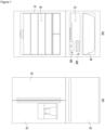
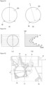
- FIG. 1 is a front view of a refrigerator according to an embodiment.
- a refrigerator may include a cabinet 14 including a storage chamber and a door that opens and closes the storage chamber.
- the storage chamber may include a refrigerating compartment 18 and a freezing compartment 32.
- the refrigerating compartment 18 is disposed at an upper side
- the freezing compartment 32 is disposed at a lower side.
- Each of the storage chamber may be opened and closed individually by each door.
- the freezing compartment may be disposed at the upper side and the refrigerating compartment may be disposed at the lower side.
- the freezing compartment may be disposed at one side of left and right sides, and the refrigerating compartment may be disposed at the other side.
- the freezing compartment 32 may be divided into an upper space and a lower space, and a drawer 40 capable of being withdrawn from and inserted into the lower space may be provided in the lower space.
- the door may include a plurality of doors 10, 20, 30 for opening and closing the refrigerating compartment 18 and the freezing compartment 32.
- the plurality of doors 10, 20, and 30 may include some or all of the doors 10 and 20 for opening and closing the storage chamber in a rotatable manner and the door 30 for opening and closing the storage chamber in a sliding manner.
- the freezing compartment 32 may be provided to be separated into two spaces even though the freezing compartment 32 is opened and closed by one door 30.
- the freezing compartment 32 may be referred to as a first storage chamber
- the refrigerating compartment 18 may be referred to as a second storage chamber.
- the freezing compartment 32 may be provided with an ice maker 200 capable of making ice.
- the ice maker 200 may be disposed, for example, in an upper space of the freezing compartment 32.
- An ice bin 600 in which the ice made by the ice maker 200 falls to be stored may be disposed below the ice maker 200.
- a user may take out the ice bin 600 from the freezing compartment 32 to use the ice stored in the ice bin 600.
- the ice bin 600 may be mounted on an upper side of a horizontal wall that partitions an upper space and a lower space of the freezing compartment 32 from each other.
- the cabinet 14 is provided with a duct supplying cold air to the ice maker 200 (not shown).
- the duct guides the cold air heat-exchanged with a refrigerant flowing through the evaporator to the ice maker 200.
- the duct may be disposed behind the cabinet 14 to discharge the cold air toward a front side of the cabinet 14.
- the ice maker 200 may be disposed at a front side of the duct.
- a discharge hole of the duct may be provided in one or more of a rear wall and an upper wall of the freezing compartment 32.
- a space in which the ice maker 200 is disposed is not limited to the freezing compartment 32.
- the ice maker 200 may be disposed in various spaces as long as the ice maker 200 receives the cold air.
- the ice maker 200 will be described as being disposed in a storage chamber.
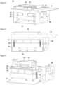
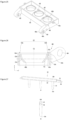
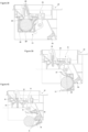
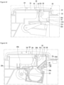
- FIG. 2 is a perspective view of the ice maker according to an embodiment
- FIG. 3 is a front view of the ice maker of FIG. 2.
- FIG. 4 is a perspective view illustrating a state in which a bracket is removed from the ice maker of FIG. 3
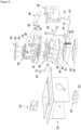
- FIG. 5 is an exploded perspective view of the ice maker according to an embodiment.
- each component of the ice maker 200 may be provided inside or outside the bracket 220, and thus, the ice maker 200 may constitute one assembly.
- the ice maker 200 may include a first tray assembly and a second tray assembly.
- the first tray assembly may include a first tray 320, a first tray case, or all of the first tray 320 and a second tray case.
- the second tray assembly may include a second tray 380, a second tray case, or all of the second tray 380 and a second tray case.
- the bracket 220 may define at least a portion of a space that accommodates the first tray assembly and the second tray assembly.
- the bracket 220 may be installed at, for example, the upper wall of the freezing compartment 32.
- the bracket 220 may be provided with a water supply part 240.
- the water supply part 240 may guide water supplied from the upper side to the lower side of the water supply part 240.
- a water supply pipe (not shown) to which water is supplied may be installed above the water supply part 240.
- the water supplied to the water supply part 240 may move downward.
- the water supply part 240 may prevent the water discharged from the water supply pipe from dropping from a high position, thereby preventing the water from splashing. Since the water supply part 240 is disposed below the water supply pipe, the water may be guided downward without splashing up to the water supply part 240, and an amount of splashing water may be reduced even if the water moves downward due to the lowered height.
- the ice maker 200 may include an ice making cell (see 320a in FIG. 30 ) in which water is phase-changed into ice by the cold air.
- the first tray 320 may constitute at least a portion of the ice making cell 320a.
- the second tray 380 may include a second tray 380 defining the other portion of the ice making cell 320a.
- the second tray 380 may be disposed to be relatively movable with respect to the first tray 320.
- the second tray 380 may linearly rotate or rotate.
- the rotation of the second tray 380 will be described as an example.
- the second tray 380 may move with respect to the first tray 320 so that the first tray 320 and the second tray 380 contact each other.
- the complete ice making cell 320a may be defined.
- the second tray 380 may move with respect to the first tray 320 during the ice making process after the ice making is completed, and the second tray 380 may be spaced apart from the first tray 320.
- the first tray 320 and the second tray 380 may be arranged in a vertical direction in a state in which the ice making cell 320a is formed. Accordingly, the first tray 320 may be referred to as an upper tray, and the second tray 380 may be referred to as a lower tray.
- a plurality of ice making cells 320a may be defined by the first tray 320 and the second tray 380.
- three ice making cells 320a are provided as an example.
- the ice making cell 320a When water is cooled by cold air while water is supplied to the ice making cell 320a, ice having the same or similar shape as that of the ice making cell 320a may be made.
- the ice making cell 320a may be provided in a spherical shape or a shape similar to a spherical shape.
- the ice making cell 320a may have a rectangular parallelepiped shape or a polygonal shape.
- the first tray case may include the first tray supporter 340 and the first tray cover 320.
- the first tray supporter 340 and the first tray cover 320 may be integrally provided or coupled to each other with each other after being manufactured in separate configurations.
- at least a portion of the first tray cover 300 may be disposed above the first tray 320.
- At least a portion of the first tray supporter 340 may be disposed under the first tray 320.
- the first tray cover 300 may be manufactured as a separate part from the bracket 220 and then may be coupled to the bracket 220 or integrally formed with the bracket 220. That is, the first tray case may include the bracket 220.
- the ice maker 200 may further include a first heater case 280.
- An ice separation heater (see 290 of FIG. 31 ) may be installed in the first heater case 280.
- the heater case 280 may be integrally formed with the first tray cover 300 or may be separately formed.
- the ice separation heater 290 may be disposed at a position adjacent to the first tray 320.
- the ice separation heater 290 may be, for example, a wire type heater.
- the ice separation heater 290 may be installed to contact the first tray 320 or may be disposed at a position spaced a predetermined distance from the first tray 320.
- the ice separation heater 290 may supply heat to the first tray 320, and the heat supplied to the first tray 320 may be transferred to the ice making cell 320a.
- the first tray cover 300 may be provided to correspond to a shape of the ice making cell 320a of the first tray 320 and may contact a lower portion of the first tray 320.
- the ice maker 200 may include a first pusher 260 separating the ice during an ice separation process.
- the first pusher 260 may receive power of the driver 480 to be described later.
- the first tray cover 300 may be provided with a guide slot 302 guiding movement of the first pusher 260.
- the guide slot 302 may be provided in a portion extending upward from the first tray cover 300.
- a guide connection part of the first pusher 260 to be described later may be inserted into the guide slot 302. Thus, the guide connection part may be guided along the guide slot 302.
- the first pusher 260 may include at least one pushing bar 264.
- the first pusher 260 may include a pushing bar 264 provided with the same number as the number of ice making cells 320a, but is not limited thereto.
- the pushing bar 264 may push out the ice disposed in the ice making cell 320a during the ice separation process.
- the pushing bar 264 may be inserted into the ice making cell 320a through the first tray cover 300. Therefore, the first tray cover 300 may be provided with an opening 304 (or through-hole) through which a portion of the first pusher 260 passes.
- the first pusher 260 may be coupled to a pusher link 500.
- the first pusher 260 may be coupled to the pusher link 500 so as to be rotatable. Therefore, when the pusher link 500 moves, the first pusher 260 may also move along the guide slot 302.
- the second tray case may include, for example, a second tray cover 360 and a second tray supporter 400.
- the second tray cover 360 and the second tray supporter 400 may be integrally formed or coupled to each other with each other after being manufactured in separate configurations.
- at least a portion of the second tray cover 360 may be disposed above the second tray 380.
- At least a portion of the second tray supporter 400 may be disposed below the second tray 380.
- the second tray supporter 400 may be disposed at a lower side of the second tray to support the second tray 380.
- At least a portion of the wall defining a second cell 381a of the second tray 380 may be supported by the second tray supporter 400.
- a spring 402 may be connected to one side of the second tray supporter 400. The spring 402 may provide elastic force to the second tray supporter 400 to maintain a state in which the second tray 380 contacts the first tray 320.
- the second tray 380 may include a circumferential wall 387 surrounding a portion of the first tray 320 in a state of contacting the first tray 320.
- the second tray cover 360 may cover at least a portion of the circumferential wall 387.
- the ice maker 200 may further include a second heater case 420.
- a transparent ice heater 430 to be described later may be installed in the second heater case 420.
- the second heater case 420 may be integrally formed with the second tray supporter 400 or may be separately provided to be coupled to the second tray supporter 400.
- the ice maker 200 may further include a driver 480 that provides driving force.
- the second tray 380 may relatively move with respect to the first tray 320 by receiving the driving force of the driver 480.
- the first pusher 260 may move by receiving the driving force of the driving force 480.
- a through-hole 282 may be defined in an extension part 281 extending downward in one side of the first tray cover 300.
- a through-hole 404 may be defined in the extension part 403 extending in one side of the second tray supporter 400. At least a portion of the through-hole 404 may be disposed at a position higher than a horizontal line passing through a center of the ice making cell 320a.
- the ice maker 200 may further include a shaft 440 (or a rotation shaft) that passes through the through-holes 282 and 404 together.
- a rotation arm 460 may be provided at each of both ends of the shaft 440.
- the shaft 440 may rotate by receiving rotational force from the driver 480.
- One end of the rotation arm 460 may be connected to one end of the spring 402, and thus, a position of the rotation arm 460 may move to an initial value by restoring force when the spring 402 is tensioned.
- the driver 480 may include a motor and a plurality of gears.
- a full ice detection lever 520 may be connected to the driver 480.
- the full ice detection lever 520 may also rotate by the rotational force provided by the driver 480.
- the full ice detection lever 520 may have a 'c' shape as a whole.
- the full ice detection lever 520 may include a first lever 521 and a pair of second levers 522 extending in a direction crossing the first lever 521 at both ends of the first lever 521.
- One of the pair of second levers 522 may be coupled to the driver 480, and the other may be coupled to the bracket 220 or the first tray cover 300.
- the full ice detection lever 520 may rotate to detect ice stored in the ice bin 600.
- the driver 480 may further include a cam that rotates by the rotational power of the motor.
- the ice maker 200 may further include a sensor that senses the rotation of the cam.
- the cam is provided with a magnet, and the sensor may be a hall sensor detecting magnetism of the magnet during the rotation of the cam.
- the sensor may output first and second signals that are different outputs according to whether the sensor senses a magnet.
- One of the first signal and the second signal may be a high signal, and the other may be a low signal.
- the controller 800 to be described later may determine a position of the second tray 380 (or the second tray assembly) based on the type and pattern of the signal outputted from the sensor.
- the position of the second tray 380 may be indirectly determined based on a detection signal of the magnet provided in the cam. For example, a water supply position, an ice making position, and an ice separation position, which will be described later, may be distinguished and determined based on the signals outputted from the sensor.
- the ice maker 200 may further include a second pusher 540.
- the second pusher 540 may be installed, for example, on the bracket 220.
- the second pusher 540 may include at least one pushing bar 544.
- the second pusher 540 may include a pushing bar 544 provided with the same number as the number of ice making cells 320a, but is not limited thereto.
- the pushing bar 544 may push out the ice disposed in the ice making cell 320a.
- the pushing bar 544 may pass through the second tray supporter 400 to contact the second tray 380 defining the ice making cell 320a and then press the contacting second tray 380.
- the first tray cover 300 may be rotatably coupled to the second tray supporter 400 with respect to the second tray supporter 400 and then be disposed to change in angle about the shaft 440.
- the second tray 380 may be made of a non-metal material.
- the second tray 380 when the second tray 380 is pressed by the second pusher 540, the second tray 380 may be made of a flexible or soft material which is deformable.
- the second tray 380 may be made of, for example, a silicon material. Therefore, while the second tray 380 is deformed while the second tray 380 is pressed by the second pusher 540, pressing force of the second pusher 540 may be transmitted to ice. The ice and the second tray 380 may be separated from each other by the pressing force of the second pusher 540.
- the coupling force or attaching force between the ice and the second tray 380 may be reduced, and thus, the ice may be easily separated from the second tray 380. Also, if the second tray 380 is made of the non-metallic material and the flexible or soft material, after the shape of the second tray 380 is deformed by the second pusher 540, when the pressing force of the second pusher 540 is removed, the second tray 380 may be easily restored to its original shape.
- the first tray 320 may be made of a metal material.
- the ice maker 200 since the coupling force or the attaching force between the first tray 320 and the ice is strong, the ice maker 200 according to this embodiment may include at least one of the ice separation heater 290 or the first pusher 260.
- the first tray 320 may be made of a non-metallic material.
- the ice maker 200 may include only one of the ice separation heater 290 and the first pusher 260.
- the ice maker 200 may not include the ice separation heater 290 and the first pusher 260.
- the first tray 320 may be made of, for example, a silicon material. That is, the first tray 320 and the second tray 380 may be made of the same material.
- the first tray 320 and the second tray 380 may have different hardness to maintain sealing performance at the contact portion between the first tray 320 and the second tray 380.
- the second tray 380 since the second tray 380 is pressed by the second pusher 540 to be deformed, the second tray 380 may have hardness less than that of the first tray 320 to facilitate the deformation of the second tray 380.
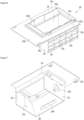
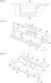
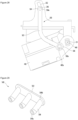
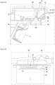
- FIGS. 6 and 7 are perspective views of the bracket according to an embodiment.
- the bracket 220 may be fixed to at least one surface of the storage chamber or to a cover member (to be described later) fixed to the storage chamber.
- the bracket 220 may include a first wall 221 having a through-hole 221a defined therein. At least a portion of the first wall 221 may extend in a horizontal direction.
- the first wall 221 may include a first fixing wall 221b to be fixed to one surface of the storage chamber or the cover member. At least a portion of the first fixing wall 221b may extend in the horizontal direction.
- the first fixing wall 221b may also be referred to as a horizontal fixing wall.
- One or more fixing protrusions 221c may be provided on the first fixing wall 221b.
- a plurality of fixing protrusions 221c may be provided on the first fixing wall 221b to firmly fix the bracket 220.
- the first wall 221 may further include a second fixing wall 221e to be fixed to one surface of the storage chamber or the cover member. At least a portion of the second fixing wall 221e may extend in a vertical direction.
- the second fixing wall 221e may also be referred to as a vertical fixing wall.
- the second fixing wall 221e may extend upward from the first fixing wall 221b.
- the second fixing wall 221e may include a fixing rib 221e1 and/or a hook 221e2.
- the first wall 221 may include at least one of the first fixing wall 221b or the second fixing wall 221e to fix the bracket 220.
- the first wall 221 may be provided in a shape in which a plurality of walls are stepped in the vertical direction.
- a plurality of walls may be arranged with a height difference in the horizontal direction, and the plurality of walls may be connected by a vertical connection wall.
- the first wall 221 may further include a support wall 221d supporting the first tray assembly. At least a portion of the support wall 221d may extend in the horizontal direction.
- the support wall 221d may be disposed at the same height as the first fixing wall 221b or disposed at a different height. In FIG. 6 , for example, the support wall 221d is disposed at a position lower than that of the first fixing wall 221b.
- the bracket 220 may further include a second wall 222 having a through-hole 222a through which cold air generated by a cooling part passes.
- the second wall 222 may extend from the first wall 221. At least a portion of the second wall 222 may extend in the vertical direction. At least a portion of the through-hole 222a may be disposed at a position higher than that of the support wall 221d. In FIG. 6 , for example, the lowermost end of the through-hole 222a is disposed at a position higher than that of the support wall 221d.
- the bracket 220 may further include a third wall 223 on which the driver 480 is installed.
- the third wall 223 may extend from the first wall 221. At least a portion of the third wall 223 may extend in the vertical direction. At least a portion of the third wall 223 may be disposed to face the second wall 222 while being spaced apart from the second wall 222. At least a portion of the ice making cell (see 320a in FIG. 49) may be disposed between the second wall 222 and the second wall 223.
- the driver 480 may be installed on the third wall 223 between the second wall 222 and the third wall 223. Alternatively, the driver 480 may be installed on the third wall 223 so that the third wall 223 is disposed between the second wall 222 and the driver 480.
- a shaft hole 223a through which a shaft of the motor constituting the driver 480 passes may be defined in the third wall 223.
- FIG. 7 illustrates that the shaft hole 223a is defined in the third wall 223.
- the bracket 220 may further include a fourth wall 224 to which the second pusher 540 is fixed.
- the fourth wall 224 may extend from the first wall 221.
- the fourth wall 224 may connect the second wall 222 to the third wall 223.
- the fourth wall 224 may be inclined at an angle with respect to the horizontal line and the vertical line.
- the fourth wall 224 may be inclined in a direction away from the shaft hole 223a from the upper side to the lower side.
- the fourth wall 224 may be provided with a mounting groove 224a in which the second pusher 540 is mounted.
- the mounting groove 224a may be provided with a coupling hole 224b through which a coupling part coupled to the second pusher 540 passes.
- the second tray 380 and the second pusher 540 may contact each other while the second tray assembly rotates while the second pusher 540 is fixed to the fourth wall 224. Ice may be separated from the second tray 380 while the second pusher 540 presses the second tray 380. When the second pusher 540 presses the second tray 380, the ice also presses the second pusher 540 before the ice is separated from the second tray 380. Force for pressing the second pusher 540 may be transmitted to the fourth wall 224. Since the fourth wall 224 is provided in a thin plate shape, a strength reinforcement member 224c may be provided on the fourth wall 224 to prevent the fourth wall 224 from being deformed or broken.
- the strength reinforcement member 224c may include ribs disposed in a lattice form. That is, the strength reinforcement member 224c may include a first rib extending in the first direction and a second rib extending in a second direction crossing the first direction. In this embodiment, two or more of the first to fourth walls 221 to 224 may define a space in which the first and second tray assemblies are disposed.
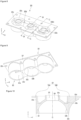
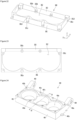
- FIG. 8 is a perspective view of the first tray when viewed from an upper side
- FIG. 9 is a perspective view of the first tray when viewed from a lower side
- FIG. 10 is a cutaway cross-sectional view taken along line 10-10 of FIG. 8 .
- the first tray 320 may define a first cell 321a that is a portion of the ice making cell 320a.
- the first tray 320 may include a first tray wall 321 defining a portion of the ice making cell 320a.
- the first tray 320 may define a plurality of first cells 321a.
- the plurality of first cells 321a may be arranged in a line.
- the plurality of first cells 321a may be arranged in an X-axis direction in FIG. 9 .
- the first tray wall 321 may define the plurality of first cells 321a.
- the first tray wall 321 may include a plurality of first cell walls 3211 that respectively define the plurality of first cells 321a, and a connection wall 3212 connecting the plurality of first cell walls 3211 to each other.
- the first tray wall 321 may be a wall extending in the vertical direction.
- the first tray 320 may include an opening 324.
- the opening 324 may communicate with the first cell 321a.
- the opening 324 may allow the cold air to be supplied to the first cell 321a.
- the opening 324 may allow water for making ice to be supplied to the first cell 321a.
- the opening 324 may provide a passage through which a portion of the first pusher 260 passes.
- the first tray 320 may include a plurality of openings 324 corresponding to the plurality of first cells 321a.
- One of the plurality of openings 324 324a may provide a passage of the cold air, a passage of the water, and a passage of the first pusher 260.
- the bubbles may escape through the opening 324.
- the first tray 320 may include a case accommodation part 321b.
- a portion of the first tray wall 321 may be recessed downward to provide the case accommodation part 321b.
- At least a portion of the case accommodation part 321b may be disposed to surround the opening 324.
- a bottom surface of the case accommodation part 321b may be disposed at a position lower than that of the opening 324. Therefore, the ice separation heater 290 and the second temperature sensor 700 may be disposed at positions lower than that of a support surface on which the first tray 320 supports the first tray cover 300.
- the first tray 320 may further include an auxiliary storage chamber 325 communicating with the ice making cell 320a.
- the auxiliary storage chamber 325 may store water overflowed from the ice making cell 320a.
- the ice expanded in a process of phase-changing the supplied water may be disposed in the auxiliary storage chamber 325. That is, the expanded ice may pass through the opening 304 and be disposed in the auxiliary storage chamber 325.
- the auxiliary storage chamber 325 may be defined by a storage chamber wall 325a.
- the storage chamber wall 325a may extend upwardly around the opening 324.
- the storage chamber wall 325a may have a cylindrical shape or a polygonal shape.
- the first pusher 260 may pass through the opening 324 after passing through the storage chamber wall 325a.
- the storage chamber wall 325a may define the auxiliary storage chamber 325 and also reduce deformation of the periphery of the opening 324 in the process in which the first pusher 260 passes through the opening 324 during the ice separation process.
- the first tray 320 defines a plurality of first cells 321a
- at least one 325b of the plurality of storage chamber walls 325a may support the water supply part 240.
- the storage chamber wall 325b supporting the water supply part 240 may have a polygonal shape.
- the storage chamber wall 325b may include a round part rounded in a horizontal direction and a plurality of straight portions.
- the storage chamber wall 325b may include a round wall 325b 1, a pair of straight walls 325b2 and 325b3 extending side by side from both ends of the round wall 325b, and a connection wall 325b4 connecting the pair of straight walls 325b2 to each other.
- the connection wall 325b4 may be a rounded wall or a straight wall.
- An upper end of the connection wall 325b4 may be disposed at a position lower than that of an upper end of the remaining walls 325b 1, 325b2, and 325b3.
- the connection wall 325b4 may support the water supply part 240.
- An opening 324a corresponding to the storage chamber wall 325b supporting the water supply part 240 may also be defined in the same shape as the storage chamber wall 325b.
- the first tray 320 may further include a heater accommodation part 321c.
- the ice separation heater 290 may be accommodated in the heater accommodation part 321c.
- the ice separation heater 290 may contact a bottom surface of the heater accommodation part 321c.
- the heater accommodation part 321c may be provided on the first tray wall 321 as an example.
- the heater accommodation part 321c may be recessed downward from the case accommodation part 321b.
- the heater accommodation part 321c may be disposed to surround the periphery of the first cell 321a. For example, at least a portion of the heater accommodation part 321c may be rounded in the horizontal direction.
- the bottom surface of the heater accommodating portion 321c may be disposed at a position lower than that of the opening 324.
- the first tray 320 may include a first contact surface 322c contacting the second tray 380.
- the bottom surface of the heater accommodating portion 321c may be disposed between the opening 324 and the first contact surface 322c. At least a portion of the heater accommodation part 321c may be disposed to overlap the ice making cell 320a (or the first cell 321a in the vertical direction).
- the first tray 320 may further include a first extension wall 327 extending in the horizontal direction from the first tray wall 321.
- the first extension wall 327 may extend in the horizontal direction around an upper end of the first extension wall 327.
- One or more first coupling holes 327a may be provided in the first extension wall 327.
- the plurality of first coupling holes 327a may be arranged in one or more axes of the X axis and the Y axis.
- An upper end of the storage chamber wall 325b may be disposed at the same height or higher than a top surface of the first extension wall 327.
- the length of the first tray 320 may be longer, but the width of the first tray 320 may be shorter than the length of the first tray 320 to prevent the volume of the first tray 320 from increasing.
- FIG. 11 is a cutaway cross-sectional view taken along line 11-11 of FIG. 8 .
- the first tray 320 may further include a sensor accommodation part 321e in which the second temperature sensor 700 (or the tray temperature sensor) is accommodated.
- the second temperature sensor 700 may sense a temperature of water or ice of the ice making cell 320a.
- the second temperature sensor 700 may be disposed adjacent to the first tray 320 to sense the temperature of the first tray 320, thereby indirectly determining the water temperature or the ice temperature of the ice making cell 320a.
- the water temperature or the ice temperature of the ice making cell 320a may be referred to as an internal temperature of the ice making cell 320a.
- the sensor accommodation part 321e may be recessed downward from the case accommodation part 321b.
- the sensor accommodation part 321e may be disposed between the two adjacent first cells 321a among the three first cells 321a arranged in the X-axis direction.
- FIG. 12 is a perspective view of the first tray cover
- FIG. 13 is a bottom perspective view of the first tray cover
- FIG. 14 is a plan view of the first tray cover
- FIG. 15 is a side view of the first tray case.
- a bottom surface of the upper plate 301 may be coupled to contact an upper side of the first tray 320.
- the upper plate 301 may contact at least one of a top surface of the first portion 322 and a top surface of the second portion 323 of the first tray 320.
- a plate opening 304 (or through-hole) may be defined in the upper plate 301.
- the plate opening 304 may include a straight portion and a curved portion.
- Water may be supplied from the water supply part 240 to the first tray 320 through the plate opening 304.
- the extension part 264 of the first pusher 260 may pass through the plate opening 304 to separate ice from the first tray 320.
- cold air may pass through the plate opening 304 to contact the first tray 320.
- a first case coupling part 301b extending upward may be disposed at a side of the straight portion of the plate opening 304 in the upper plate 301.
- the first case coupling part 301b may be coupled to the first heater case 280.
- the first tray cover 300 may further include a circumferential wall 303 extending upward from an edge of the upper plate 301.
- the circumferential wall 303 may include two pairs of walls facing each other. For example, the pair of walls may be spaced apart from each other in the X-axis direction, and another pair of walls may be spaced apart from each other in the Y-axis direction.
- the circumferential walls 303 spaced apart from each other in the Y-axis direction of FIG. 12 may include an extension wall 302e extending upward.
- the extension wall 302e may extend upward from a top surface of the circumferential wall 303.
- the first tray cover 300 may include a pair of guide slots 302 guiding the movement of the first pusher 260.
- a portion of the guide slot 302 may be defined in the extension wall 302e, and the other portion may be defined in the circumferential wall 303 disposed below the extension wall 302e.
- a lower portion of the guide slot 302 may be defined in the circumferential wall 303.
- the guide slot 302 may extend in the Z-axis direction of FIG. 12 .
- the first pusher 260 may be inserted into the guide slot 302 to move. Also, the first pusher 260 may move up and down along the guide slot 302.
- the guide slot 302 may include a first slot 302a extending perpendicular to the upper plate 301 and a second slot 302b that is bent at an angle from an upper end of the first slot 302a.
- the guide slot 302 may include only the first slot 302a extending in the vertical direction.
- the lower end 302d of the first slot 302a may be disposed lower than the upper end of the circumferential wall 303.
- the upper end 302c of the first slot 302a may be disposed higher than the upper end of the circumferential wall 303.
- the portion bent from the first slot 302a to the second slot 302b may be disposed at a position higher than the circumferential wall 303.
- a plurality of vertical coupling parts 303a may be provided on the other one of the circumferential walls 303 spaced apart from and facing each other in the Y-axis direction.
- the vertical coupling part 303a may be coupled to the first wall 221 of the bracket 220.
- the vertical coupling parts 303a may be arranged to be spaced apart from each other in the X-axis direction.
- the upper plate 301 may be provided with a lower protrusion 306 protruding downward.
- the lower protrusion 306 may extend along the length of the upper plate 301 and may be disposed around the circumferential wall 303 of the other of the circumferential walls 303 spaced apart from each other in the Y-axis direction.
- the wire guide slots 313a and 315a may be defined in the upper plate 310 to correspond to the first and second protrusions 313 and 315, and a portion of the wire may be the wire guide slots 313a and 315a to prevent the wire from being separated.
- FIG. 16 is a plan view of a first tray supporter.
- the first tray supporter 340 may be coupled to the first tray cover 300 to support the first tray 320.
- the first tray supporter 340 includes a horizontal portion 341 contacting a bottom surface of the upper end of the first tray 320 and an insertion opening 342 through which a lower portion of the first tray 320 is inserted into a center of the horizontal portion 341.
- the horizontal portion 341 may have a size corresponding to the upper plate 301 of the first tray cover 300.
- the horizontal portion 341 may include a plurality of coupling holes 341a engaged with the coupling parts 301a of the first tray cover 300.
- the plurality of coupling holes 341a may be spaced apart from each other in the X-axis and/or Y-axis direction of FIG. 16 to correspond to the coupling part 301a of the first tray cover 300.
- the upper plate 301 of the first tray cover 300, the first tray 320, and the first tray supporter 340 may sequentially contact each other.
- the bottom surface of the upper plate 301 of the first tray cover 300 and the top surface of the first extension wall 327 of the first tray 320 may contact each other, and the bottom surface of the first extension wall 327 of the first tray 320 and the top surface of the horizontal part 341 of the first tray supporter 340 may contact each other.
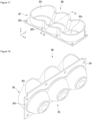
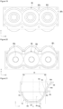
- FIG. 17 is a perspective view of a second tray according to an embodiment
- FIG. 18 is a perspective view of the second tray when viewed from a lower side.
- FIG. 19 is a bottom view of the second tray
- FIG. 20 is a plan view of the second tray.
- the second tray 380 may define a second cell 381a which is another portion of the ice making cell 320a.
- the second tray 380 may include a second tray wall 381 defining a portion of the ice making cell 320a.
- the second tray 380 may define a plurality of second cells 381a.
- the plurality of second cells 381a may be arranged in a line.
- the plurality of second cells 381a may be arranged in the X-axis direction.
- the second tray wall 381 may define the plurality of second cells 381a.
- the second tray wall 381 may include a plurality of second cell walls 3811 which respectively define the plurality of second cells 381a.
- the two adjacent second cell walls 3811 may be connected to each other.
- the second tray 380 may include a circumferential wall 387 extending along a circumference of an upper end of the second tray wall 381.
- the circumferential wall 387 may be formed integrally with the second tray wall 381 and may extend from an upper end of the second tray wall 381.
- the circumferential wall 387 may be provided separately from the second tray wall 381 and disposed around the upper end of the second tray wall 381. In this case, the circumferential wall 387 may contact the second tray wall 381 or be spaced apart from the third tray wall 381.
- the circumferential wall 387 may surround at least a portion of the first tray 320. If the second tray 380 includes the circumferential wall 387, the second tray 380 may surround the first tray 320.
- the circumferential wall 387 may be integrally formed with the second tray case or may be coupled to the second tray case.
- one second tray wall may define a plurality of second cells 381a, and one continuous circumferential wall 387 may surround the first tray 250.
- the circumferential wall 387 may include a first extension wall 387b extending in the horizontal direction and a second extension wall 387c extending in the vertical direction.
- the first extension wall 387b may be provided with one or more second coupling holes 387a to be coupled to the second tray case.
- the plurality of second coupling holes 387a may be arranged in at least one axis of the X axis or the Y axis.
- the second tray 380 may include a second contact surface 382c contacting the first contact surface 322c of the first tray 320.
- the first contact surface 322c and the second contact surface 382c may be horizontal planes.
- Each of the first contact surface 322c and the second contact surface 382c may be provided in a ring shape. When the ice making cell 320a has a spherical shape, each of the first contact surface 322c and the second contact surface 382c may have a circular ring shape.
- FIG. 21 is a cutaway cross-sectional view taken along line 21-21 of FIG. 17 .
- FIG. 21 illustrates a Y-Z cutting surface passing through the central line C1.
- the second tray 380 may include a first portion 382 that defines at least a portion of the ice making cell 320a.
- the first portion 382 may be a portion or the whole of the second tray wall 381.
- first portion 322 of the first tray 320 may be referred to as a third part so as to be distinguished from the first portion 382 of the second tray 380.
- second portion 323 of the first tray 320 may be referred to as a fourth portion so as to be distinguished from the second portion 383 of the second tray 380.
- the first portion 382 may include a second cell surface 382b (or an outer circumferential surface) defining the second cell 381a of the ice making cell 320a.
- the first portion 382 may be defined as an area between two dotted lines in FIG. 21 .
- the uppermost end of the first portion 382 is the second contact surface 382c contacting the first tray 320.
- the second tray 380 may further include a second portion 383.
- the second portion 383 may reduce transfer of heat, which is transferred from the transparent ice heater 430 to the second tray 380, to the ice making cell 320a defined by the first tray 320. That is, the second portion 383 serves to allow the heat conduction path to move in a direction away from the first cell 321a.
- the second portion 383 may be a portion or the whole of the circumferential wall 387.
- the second portion 383 may extend from a predetermined point of the first portion 382. In the following description, for example, the second portion 383 is connected to the first portion 382.
- the predetermined point of the first portion 382 may be one end of the first portion 382.
- the predetermined point of the first portion 382 may be one point of the second contact surface 382c.
- the second portion 383 may include the other end that does not contact one end contacting the predetermined point of the first portion 382.
- the other end of the second portion 383 may be disposed farther from the first cell 321a than one end of the second portion 383.
- At least a portion of the second portion 383 may extend in a direction away from the first cell 321a. At least a portion of the second portion 383 may extend in a direction away from the second cell 381a. At least a portion of the second portion 383 may extend upward from the second contact surface 382c. At least a portion of the second portion 383 may extend horizontally in a direction away from the central line C1. A center of curvature of at least a portion of the second portion 383 may coincide with a center of rotation of the shaft 440 which is connected to the driver 480 to rotate.
- the second portion 383 may include a first part 384a extending from one point of the first portion 382.
- the second portion 383 may further include a second part 384b extending in the same direction as the extending direction with the first part 384a.
- the second portion 383 may further include a third part 384b extending in a direction different from the extending direction of the first part 384a.
- the second portion 383 may further include a second part 384b and a third part 384c branched from the first part 384a.
- the first part 384a may extend in the horizontal direction from the first portion 382.
- a portion of the first part 384a may be disposed at a position higher than that of the second contact surface 382c.
- the first part 384a may include a horizontally extension part and a vertically extension part.
- the first part 384a may further include a portion extending in the vertical direction from the predetermined point.
- a length of the third part 384c may be greater than that of the second part 384b.
- the extension direction of at least a portion of the first part 384a may be the same as that of the second part 384b.
- the extension directions of the second part 384b and the third part 384c may be different from each other.
- the extension direction of the third part 384c may be different from that of the first part 384a.
- the third part 384a may have a constant curvature based on the Y-Z cutting surface. That is, the same curvature radius of the third part 384a may be constant in the longitudinal direction.
- the curvature of the second part 384b may be zero. When the second part 384b is not a straight line, the curvature of the second part 384b may be less than that of the third part 384a.
- the curvature radius of the second part 384b may be greater than that of the third part 384a.
- At least a portion of the second portion 383 may be disposed at a position higher than or equal to that of the uppermost end of the ice making cell 320a. In this case, since the heat conduction path defined by the second portion 383 is long, the heat transfer to the ice making cell 320a may be reduced.
- a length of the second portion 383 may be greater than the radius of the ice making cell 320a.
- the second portion 383 may extend up to a point higher than the center of rotation C4 of the shaft 440. For example, the second portion 383 may extend up to a point higher than the uppermost end of the shaft 440.
- the second portion 383 may include a first extension part 383a extending from a first point of the first portion 382 and a second extension part 383b extending from a second point of the first portion 382 so that transfer of the heat of the transparent ice heater 430 to the ice making cell 320a defined by the first tray 320 is reduced.
- the first extension part 383a and the second extension part 383b may extend in different directions with respect to the central line C1.
- the first extension part 383a may be disposed at the left side with respect to the central line C1, and the second extension part 383b may be disposed at the right side with respect to the central line C1.
- the first extension part 383a and the second extension part 383b may have different shapes based on the central line C1.
- the first extension part 383a and the second extension part 383b may be provided in an asymmetrical shape with respect to the central line C1.
- a length (horizontal length) of the second extension part 383b in the Y-axis direction may be longer than the length (horizontal length) of the first extension part 383a.
- the first extension part 383a may be disposed closer to an edge part that is disposed at a side opposite to the portion of the second wall 222 or the third wall 223 of the bracket 220, which is connected to the fourth wall 224, than the second extension part 383a.
- the second extension part 383b may be disposed closer to the shaft 440 that provides a center of rotation of the second tray assembly than the first extension part 383a.
- a length of the second extension part 383b in the Y-axis direction may be greater than that of the first extension part 383a.
- the heat conduction path may increase while reducing the width of the bracket 220 relative to the space in which the ice maker 200 is installed. Since the length of the second extension part 383b in the Y-axis direction is greater than that of the first extension part 383a, the second tray assembly including the second tray 380 contacting the first tray 320 may increase in radius of rotation. When the rotation radius of the second tray assembly increases centrifugal force of the second tray assembly may increase. Thus, in the ice separation process, separating force for separating the ice from the second tray assembly may increase to improve ice separation performance.
- the center of curvature of at least a portion of the second extension part 383b may be a center of curvature of the shaft 440 which is connected to the driver 480 to rotate.
- a distance between an upper portion of the first extension part 383a and an upper portion of the second extension part 383b may be greater than that between a lower portion of the first extension part 383a and a lower portion of the second extension part 383b with respect to the Y-Z cutting surface passing through the central line C1.
- a distance between the first extension part 383a and the second extension part 383b may increase upward.
- Each of the first extension part 383a and the third extension part 383b may include first to third parts 384a, 384b, and 384c.
- the third part 384c may also be described as including the first extension part 383a and the second extension part 383b extending in different directions with respect to the central line C 1.
- the first portion 382 may have a variable radius in the Y-axis direction.
- the first portion 382 may include a first region 382d (see region A in FIG. 21 ) and a second region 382e.
- the curvature of at least a portion of the first region 382d may be different from that of at least a portion of the second region 382e.
- the first region 382d may include the lowermost end of the ice making cell 320a.
- the second region 382e may have a diameter greater than that of the first region 382d.
- the first region 382d and the second region 382e may be divided vertically.
- the transparent ice heater 430 may contact the first region 382d.
- the first region 382d may include a heater contact surface 382g contacting the transparent ice heater 430.
- the heater contact surface 382g may be, for example, a horizontal plane.
- the heater contact surface 382g may be disposed at a position higher than that of the lowermost end of the first portion 382.
- the second region 382e may include the second contact surface 382c.
- the first region 382d may have a shape recessed in a direction opposite to a direction in which ice is expanded in the ice making cell 320a.
- a distance from the center of the ice making cell 320a to the second region 382e may be less than that from the center of the ice making cell 320a to the portion at which the shape recessed in the first area 382d is disposed.
- the first region 382d may include a pressing part 382f that is pressed by the second pusher 540 during the ice separation process. When pressing force of the second pusher 540 is applied to the pressing part 382f, the pressing part 382f is deformed, and thus, ice is separated from the first portion 382.
- the central line C1 may pass through the first region 382d.
- the central line C1 may pass through the pressing part 382f.
- the heater contact surface 382g may be disposed to surround the pressing unit 382f.
- the heater contact surface 382g may be disposed at a position higher than that of the lowermost end of the pressing part 382f.
- At least a portion of the heater contact surface 382g may be disposed to surround the central line C1. Accordingly, at least a portion of the transparent ice heater 430 contacting the heater contact surface 382g may be disposed to surround the central line C1.
- the transparent ice heater 430 may be prevented from interfering with the second pusher 540 while the second pusher 540 presses the pressing unit 382f.
- a distance from the center of the ice making cell 320a to the pressing part 382f may be different from that from the center of the ice making cell 320a to the second region 382e.
- FIG. 22 is a perspective view of the second tray cover
- FIG. 23 is a plan view of the second tray cover.
- the second tray cover 360 includes an opening 362 (or through-hole) into which a portion of the second tray 380 is inserted.
- an opening 362 or through-hole
- a portion of the second tray 380 may protrude upward from the second tray cover 360 through the opening 362.
- the second tray cover 360 may include a vertical wall 361 and a curved wall 363 surrounding the opening 362.
- the vertical wall 361 may define three surfaces of the second tray cover 360, and the curved wall 363 may define the other surface of the second tray cover 360.
- the vertical wall 361 may be a wall extending vertically upward, and the curved wall 363 may be a wall rounded away from the opening 362 upward.
- the vertical walls 361 and the curved walls 363 may be provided with a plurality of coupling parts 361a, 361c, and 363a to be coupled to the second tray 380 and the second tray case 400.
- the vertical wall 361 and the curved wall 363 may further include a plurality of coupling grooves 361b, 361d, and 363b corresponding to the plurality of coupling parts 361a, 361c, and 363a.
- a coupling member may be inserted into the plurality of coupling parts 361a, 361c, and 363a to pass through the second tray 380 and then be coupled to the coupling parts 401a, 401b, and 401c of the second tray supporter 400.
- the coupling part may protrude upward from the vertical wall 361 and the curved wall 363 through the plurality of coupling grooves 361b, 361d, and 363b to prevent an interference with other components.
- a plurality of first coupling parts 361a may be provided on the wall facing the curved wall 363 of the vertical wall 361.
- the plurality of first coupling parts 361a may be spaced apart from each other in the X-axis direction of FIG. 22 .
- a first coupling groove 361b corresponding to each of the first coupling parts 361a may be provided.
- the first coupling groove 361b may be defined by recessing the vertical wall 361, and the first coupling part 361a may be provided in the recessed portion of the first coupling groove 361b.
- the vertical wall 361 may further include a plurality of second coupling parts 361c.
- the plurality of second coupling parts 361c may be provided on the vertical walls 361 that are spaced apart from each other in the X-axis direction.
- the plurality of second coupling parts 361c may be disposed closer to the first coupling parts 361a than the third coupling parts 363a, which will be described later. This is done for preventing the interference with the extension 403 of the second tray supporter 400 when being coupled to a second tray supporter 400 that will be described later.
- the vertical wall 361 in which the plurality of second coupling parts 361c are disposed may further include a second coupling groove 361d defined by spacing portions except for the second coupling parts 361c apart from each other.
- the curved wall 363 may be provided with a plurality of third coupling parts 363a to be coupled to the second tray 380 and the second tray supporter 400.
- the plurality of third coupling parts 363a may be spaced apart from each other in the X-axis direction of FIG. 22 .
- the curved wall 363 may be provided with a third coupling groove 363b corresponding to each of the third coupling parts 363a.
- the third coupling groove 363b may be defined by vertically recessing the curved wall 363, and the third coupling part 363a may be provided in the recessed portion of the third coupling groove 363b.
- the second tray cover 360 may support at least a portion of the second portion 383 of the second tray 380.
- the second tray cover 360 may support the first extension part 383a and the second extension part 383b of the second portion 383.
- FIG. 24 is a top perspective view of a second tray supporter
- FIG. 25 is a bottom perspective view of the second tray supporter
- FIG. 26 is a cutaway cross-sectional view taken along line 26-26 of FIG. 24 .
- the second tray supporter 400 may include a support body 407 on which a lower portion of the second tray 380 is seated.
- the support body 407 may include an accommodation space 406a in which a portion of the second tray 380 is accommodated.
- the accommodation space 406a may be defined corresponding to the first portion 382 of the second tray 380, and a plurality of accommodation spaces 406a may be provided.
- the support body 407 may include a lower opening 406b (or a through-hole) through which a portion of the second pusher 540 passes.
- a lower opening 406b (or a through-hole) through which a portion of the second pusher 540 passes.
- three lower openings 406b may be provided in the support body 407 to correspond to the three accommodation spaces 406a.
- a portion of the lower portion of the second tray 380 may be exposed by the lower opening 406b.
- At least a portion of the second tray 380 may be disposed in the lower opening 406b.
- a portion of the second tray 380 may contact the support body 404 by the lower opening 406b.
- a surface area of the area contacting the support body 407 may be greater than that of the non-contact area.
- a top surface 407a of the support body 407 may extend in the horizontal direction.
- the second tray supporter 400 may include a top surface 407a of the support body 407 and a stepped lower plate 401.
- the lower plate 401 may be disposed at a position higher than that of the top surface 407a of the support body 407.
- the lower plate 401 may include a plurality of coupling parts 401a, 401b, and 401c to be coupled to the second tray cover 360.
- the second tray 380 may be inserted and coupled between the second tray cover 360 and the second tray supporter 400.
- the second tray 380 may be disposed below the second tray cover 360, and the second tray 380 may be accommodated above the second tray supporter 400.
- the first extension wall 387b of the second tray 380 may be coupled to the coupling parts 361a, 361b, and 361c of the second tray cover 360 and the coupling parts 400a, 401b, and 401c of the second tray supporter 400.
- the plurality of first coupling parts 401a may be spaced apart from each other in the X-axis direction.
- first coupling part 401a and the second and third coupling parts 401b and 401c may be spaced apart from each other in the Y-axis direction.
- the third coupling part 401c may be disposed farther from the first coupling part 401a than the second coupling part 401b.
- the second tray supporter 400 may further include a vertical extension wall 405 extending vertically downward from an edge of the lower plate 401.
- One surface of the vertical extension wall 405 may be provided with a pair of extension parts 403 coupled to the shaft 440 to allow the second tray 380 to rotate.
- the pair of extension parts 403 may be spaced apart from each other in the X-axis direction. Also, each of the extension parts 403 may further include a through-hole 404.
- the shaft 440 may pass through the through-hole 404, and the extension part 281 of the first tray cover 300 may be disposed inside the pair of extension parts 403.
- the through-hole 404 may further include a central portion 404a and an extension hole 404b extending symmetrically to the central portion 404a.
- the second tray supporter 400 may further include a spring coupling part 402a to which a spring 402 is coupled.
- the spring coupling part 402a may provide a ring to be hooked with a lower end of the spring 402.
- One of the walls spaced apart from and facing each other in the X-axis direction of the vertical extension wall 405 is provided with a guide hole 408 guiding the transparent ice heater 430 to be described later or the wire connected to the transparent ice heater 430.
- the second tray supporter 400 may further include a link connection part 405a to which the pusher link 500 is coupled.
- the link connection part 405a may protrude from the vertical extension wall 405 in the X-axis direction.
- the link connection part 405a may be disposed on an area between the center line CL1 and the through-hole 404 with respect to FIG. 26 .
- the lower plate 401 may further include a plurality of second heater coupling parts 409 coupled to the second heater case 420.
- the plurality of second heater coupling parts 409 may be arranged to be spaced apart from each other in the X-axis direction and/or the Y-axis direction.
- the second tray supporter 400 may include a first portion 411 supporting the second tray 380 defining at least a portion of the ice making cell 320a.
- the first portion 411 may be an area between two dotted lines.
- the support body 407 may define the first portion 411.
- the second tray supporter 400 may further include a second portion 413 extending from a predetermined point of the first portion 411.
- the second portion 413 may reduce transfer of heat, which is transfer from the transparent ice heater 430 to the second tray supporter 400, to the ice making cell 320a defined by the first tray 320. At least a portion of the second portion 413 may extend in a direction away from the first cell 321a defined by the first tray 320.
- the direction away from the first cell 321 may be a horizontal direction passing through the center of the ice making cell 320a.
- the direction away from the first cell 321 may be a downward direction with respect to a horizontal line passing through the center of the ice making cell 320a.
- the second portion 413 may include a first part 414a extending in the horizontal direction from the predetermined point and a second part 414b extending in the same direction as the first part 414a.
- the second portion 413 may include a first part 414a extending in the horizontal direction from the predetermined point, and a third part 414c extending in a direction different from that of the first part 414a.
- the second portion 413 may include a first part 414a extending in the horizontal direction from the predetermined point, and a second part 414b and a third part 414c, which are branched from the first part 414a.
- a top surface 407a of the support body 407 may provide, for example, the first part 414a.
- the first part 414a may further include a fourth part 414d extending in the vertical line direction.
- the lower plate 401 may provide, for example, the fourth part 414d.
- the vertical extension wall 405 may provide, for example, the third part 414c.
- a length of the third part 414c may be greater than that of the second part 414b.
- the second part 414b may extend in the same direction as the first part 414a.
- the third part 414c may extend in a direction different from that of the first part 414a.
- the second portion 413 may be disposed at the same height as the lowermost end of the first cell 321a or extend up to a lower point.
- the second portion 413 may include a first extension part 413a and a second extension part 413b which are disposed opposite to each other with respect to the center line CL1 corresponding to the center line C1 of the ice making cell 320a.
- the first extension part 413a may be disposed at a left side with respect to the center line CL1
- the second extension part 413b may be disposed at a right side with respect to the center line CL1.
- the first extension part 413a and the second extension part 413b may have different shapes with respect to the center line CL1.
- the first extension part 413a and the second extension part 413b may have shapes that are asymmetrical to each other with respect to the center line CL1.
- a length of the second extension part 413b may be greater than that of the first extension part 413a in the horizontal direction. That is, a length of the thermal conductivity of the second extension 413b is greater than that of the first extension part 413a.
- the first extension part 413a may be disposed closer to an edge part that is disposed at a side opposite to the portion of the second wall 222 or the third wall 223 of the bracket 220, which is connected to the fourth wall 224, than the second extension part 413b.
- the second extension part 413b may be disposed closer to the shaft 440 that provides a center of rotation of the second tray assembly than the first extension part 413a.
- the second tray assembly including the second tray 380 contacting the first tray 320 may increase in radius of rotation.
- a center of curvature of at least a portion of the second extension part 413a may coincide with a center of rotation of the shaft 440 which is connected to the driver 480 to rotate.
- the first extension part 413a may include a portion 414e extending upwardly with respect to the horizontal line.
- the portion 414e may surround, for example, a portion of the second tray 380.
- the second tray supporter 400 may include a first region 415a including the lower opening 406b and a second region 415b having a shape corresponding to the ice making cell 320a to support the second tray 380.
- the first region 415a and the second region 415b may be divided vertically.
- the first region 415a and the second region 415b are divided by a dashed-dotted line that is extended in a horizontal direction.
- the first region 415a may support the second tray 380.
- the controller controls the ice maker to allow the second pusher 540 to move from a first point outside the ice making cell 320a to a second point inside the second tray supporter 400 via the lower opening 406b.
- a degree of deformation resistance of the second tray supporter 400 may be greater than that of the second tray 380.
- a degree of restoration of the second tray supporter 400 may be less than that of the second tray 380.
- the second tray supporter 400 includes a first region 415a including a lower opening 406b and a second region 415b disposed farther from the transparent ice heater 430 than the first region 415a.
- the transparent ice heater 430 will be described in detail.
- the controller 800 may control the transparent ice heater 430 so that heat is supplied to the ice making cell 320a in at least partial section while cold air is supplied to the ice making cell 320a to make the transparent ice.
- An ice making rate may be delayed so that bubbles dissolved in water within the ice making cell 320a may move from a portion at which ice is made toward liquid water by the heat of the transparent ice heater 430, thereby making transparent ice in the ice maker 200. That is, the bubbles dissolved in water may be induced to escape to the outside of the ice making cell 320a or to be collected into a predetermined position in the ice making cell 320a.
- a cold air supply part 900 to be described later supplies cold air to the ice making cell 320a, if the ice making rate is high, the bubbles dissolved in the water inside the ice making cell 320a may be frozen without moving from the portion at which the ice is made to the liquid water, and thus, transparency of the ice may be reduced.
- the cold air supply part 900 supplies the cold air to the ice making cell 320a, if the ice making rate is low, the above limitation may be solved to increase in transparency of the ice.
- the transparent ice heater 430 may be disposed at one side of the ice making cell 320a so that the heater locally supplies heat to the ice making cell 320a, thereby increasing in transparency of the made ice while reducing the ice making time.
- the transparent ice heater 430 When the transparent ice heater 430 is disposed on one side of the ice making cell 320a, the transparent ice heater 430 may be made of a material having thermal conductivity less than that of the metal to prevent heat of the transparent ice heater 430 from being easily transferred to the other side of the ice making cell 320a.
- At least one of the first tray 320 and the second tray 380 may be made of a resin including plastic so that the ice attached to the trays 320 and 380 is separated in the ice making process.
- At least one of the first tray 320 or the second tray 380 may be made of a flexible or soft material so that the tray deformed by the pushers 260 and 540 is easily restored to its original shape in the ice separation process.
- the transparent ice heater 430 may be disposed at a position adjacent to the second tray 380.
- the transparent ice heater 430 may be, for example, a wire type heater.
- the transparent ice heater 430 may be installed to contact the second tray 380 or may be disposed at a position spaced a predetermined distance from the second tray 380.
- the second heater case 420 may not be separately provided, but the transparent heater 430 may be installed on the second tray supporter 400.
- the transparent ice heater 430 may supply heat to the second tray 380, and the heat supplied to the second tray 380 may be transferred to the ice making cell 320a.
- FIG. 27 is a view of the first pusher according to an embodiment, wherein FIG. 27(a) is a perspective view of the first pusher, and FIG. 27(b) is a side view of the first pusher.
- the first pusher 260 may include a pushing bar 264.
- the pushing bar 264 may include a first edge 264a on which a pressing surface pressing ice or a tray in the ice separation process is disposed and a second edge 264b disposed at a side opposite to the first edge 264a.
- the pressing surface may be flat or curved surface.
- the pushing bar 264 may extend in the vertical direction and may be provided in a straight line shape or a curved shape in which at least a portion of the pushing bar 264 is rounded. A diameter of the pushing bar 264 is less than that of the opening 324 of the first tray 320. Accordingly, the pushing bar 264 may be inserted into the ice making cell 320a through the opening 324. Thus, the first pusher 260 may be referred to as a penetrating type passing through the ice making cell 320a.
- the first pusher 260 may include a plurality of pushing bars 264. Two adjacent pushing bars 264 may be connected to each other by the connection part 263.
- the connection part 263 may connect upper ends of the pushing bars 264 to each other. Thus, the second edge 264a and the connection part 263 may be prevented from interfering with the first tray 320 while the pushing bar 264 is inserted into the ice making cell 320a.
- the first pusher 260 may include a guide connection part 265 passing through the guide slot 302.
- the guide connection part 265 may be provided at each of both sides of the first pusher 260.
- a vertical cross-section of the guide connection part 265 may have a circular, oval, or polygonal shape.
- the guide connection part 265 may be disposed in the guide slot 302.
- the guide connection part 265 may move in a longitudinal direction along the guide slot 302 in a state of being disposed in the guide slot 302.
- the guide connection part 265 may move in the vertical direction.
- the guide slot 302 has been described as being provided in the first tray cover 300, it may be alternatively provided in the wall defining the bracket 220 or the storage chamber.
- the guide connection part 265 may further include a link connection part 266 to be coupled to the pusher link 500.
- the link connection part 266 may be disposed at a position lower than that of the second edge 264b.
- the link connection part 266 may be provided in a cylindrical shape so that the link connection part 266 rotates in the state in which the link connection part 266 is coupled to the pusher link 500.
- FIG. 28 is a view illustrating a state in which the first pusher is connected to the second tray assembly by the link.
- the pusher link 500 may connect the first pusher 500 to the second tray assembly.
- the pusher link 500 may be connected to the first pusher 260 and the second tray case.
- the pusher link 500 may include a link body 502.
- the link body 502 may have a rounded shape. As the link body 502 is provided in a round shape, the pusher link 500 may allow the first pusher 260 to rotate and also to vertically move while the second tray assembly rotates.
- the pusher link 500 may include a first connection part 504 provided at one end of the link body 502 and a second connection part 506 provided at the other end of the link body 502.
- the first connection part 504 may include a first coupling hole 504a to which the link connection part 266 is coupled.
- the link connection part 266 may be connected to the first connection part 504 after passing through the guide slot 302.
- the second connection part 506 may be coupled to the second tray supporter 400.
- the second connection part 506 may include a second coupling hole 506a to which the link connection part 405a provided on the second tray supporter 400 is coupled.
- the second connection part 504 may be connected to the second tray supporter 400 at a position spaced apart from the rotation center C4 of the shaft 440 or the rotation center C4 of the second tray assembly. Therefore, according to this embodiment, the pusher link 500 connected to the second tray assembly rotates together by the rotation of the second tray assembly. While the pusher link 500 rotates, the first pusher 260 connected to the pusher link 500 moves vertically along the guide slot 302.
- the pusher link 502 may serve to convert rotational force of the second tray assembly into vertical movement force of the first pusher 260. Accordingly, the first pusher 260 may also be referred to as a movable pusher.
- FIG. 29 is a perspective view of the second pusher according to an embodiment.
- the second pusher 540 may include a pushing bar 544.
- the pushing bar 544 may include a first edge 544a on which a pressing surface pressing the second tray 380 is disposed and a second edge 544b disposed at a side opposite to the first edge 544a.
- the pushing bar 544 may have a curved shape to increase in time taken to press the second tray 380 without interfering with the second tray 380 that rotates in the ice separation process.
- the first edge 544a may be a plane and include a vertical surface or an inclined surface.
- the second edge 544b may be coupled to the fourth wall 224 of the bracket 220, or the second edge 544b may be coupled to the fourth wall 224 of the bracket 220 by the coupling plate 542.
- the coupling plate 542 may be seated in the mounting groove 224a defined in the fourth wall 224 of the bracket 220.
- the second pusher 540 may include a plurality of pushing bars 544.
- the plurality of pushing bars 544 may be connected to the coupling plate 542 while being spaced apart from each other in the horizontal direction.
- the plurality of pushing bars 544 may be integrally formed with the coupling plate 542 or coupled to the coupling plate 542.
- the first edge 544a may be disposed to be inclined with respect to the center line C1 of the ice making cell 320a.
- the first edge 544a may be inclined in a direction away from the center line C1 of the ice making cell 320a from an upper end toward a lower end.
- An angle of the inclined surface defined by the first edge 544a with respect to the vertical line may be less than that of the inclined surface defined by the second edge 544b.
- the direction in which the pushing bar 544 extends from the center of the first edge 544a toward the center of the second edge 544a may include at least two directions.
- the pushing bar 544 may include a first part extending in a first direction and a second portion extending in a direction different from the second portion. At least a portion of the line connecting the center of the second edge 544a to the center of the first edge 544a along the pushing bar 544 may be curved.
- the first edge 544a and the second edge 544b may have different heights.
- the first edge 544a may be disposed to be inclined with respect to the second edge 544b.
- FIG. 30 is a cutaway cross-sectional view taken along line 30-30 of FIG. 2 .
- the ice maker 200 may include a first tray assembly 201 and a second tray assembly 211, which are connected to each other.
- the second tray assembly 211 may include a first portion 212 defining at least a portion of the ice making cell 320a and a second portion 213 extending from a predetermined point of the first portion 212.
- the second portion 213 may reduce transfer of heat from the transparent ice heater 430 to the ice making cell 320a defined by the first tray assembly 201.
- the first portion 212 may be an area disposed between two dotted lines in FIG. 30 .
- the predetermined point of the first portion 212 may be an end of the first portion 212 or a point at which the first tray assembly 201 and the second tray assembly 211 meet each other. At least a portion of the first portion 212 may extend in a direction away from the ice making cell 320a defined by the first tray assembly 201. At least two portions of the second portion 213 may be branched to reduce heat transfer in the direction extending to the second portion 213. A portion of the second portion 213 may extend in the horizontal direction passing through the center of the ice making cell 320a. A portion of the second portion 213 may extend in an upward direction with respect to a horizontal line passing through the center of the ice making chamber 320a.
- the second portion 213 includes a first part 213c extending in the horizontal direction passing through the center of the ice making cell 320a, a second part 213d extending upward with respect to the horizontal line passing through the center of the ice making cell 320a, a third part 213e extending downward.
- the first portion 212 may have different degree of heat transfer in a direction along the outer circumferential surface of the ice making cell 320a to reduce transfer of heat, which is transferred from the transparent ice heater 430 to the second tray assembly 211, to the ice making cell 320a defined by the first tray assembly 201.
- the transparent ice heater 430 may be disposed to heat both sides with respect to the lowermost end of the first portion 212.
- the first portion 212 may include a first region 214a and a second region 214b.
- the first region 214a and the second region 214b are divided by a dashed-dotted line that is extended in a horizontal direction.
- the second region 214b may be a region defined above the first region 214a. The degree of heat transfer of the second region 214b may be greater than that of the first region 214a.
- the first region 214a may include a portion at which the transparent ice heater 430 is disposed. That is, the transparent ice heater 430 may be disposed in the first region 214a.
- the lowermost end 214a1 of the ice making cell 320a in the first region 214a may have a heat transfer rate less than that of the other portion of the first region 214a.
- the second region 214b may include a portion in which the first tray assembly 201 and the second tray assembly 211 contact each other.
- the first region 214a may provide a portion of the ice making cell 320a.
- the second region 214b may provide the other portion of the ice making cell 320a.
- the second region 214b may be disposed farther from the transparent ice heater 430 than the first region 214a.
- Part of the first region 214a may have the degree of heat transfer less than that of the other part of the first region 214a to reduce transfer of heat, which is transferred from the transparent ice heater 430 to the first region 314a, to the ice making cell 320a defined by the second region 214b.
- a portion of the first region 214a may have a degree of deformation resistance less than that of the other portion of the first region 214a and a degree of restoration greater than that of the other portion of the first region 214a.
- a portion of the first region 214a may be thinner than the other portion of the first region 214a in the thickness direction from the center of the ice making cell 320a to the outer circumferential surface direction of the ice making cell 320a.
- the first region 214a may include a second tray case surrounding at least a portion of the second tray 380 and at least a portion of the second tray 380.
- An average cross-sectional area or average thickness of the first tray assembly 201 may be greater than that of the second tray assembly 211 with respect to the Y-Z cutting surface.
- a maximum cross-sectional area or maximum thickness of the first tray assembly 201 may be greater than that of the second tray assembly 211 with respect to the Y-Z cutting surface.
- the rotation center C4 may be eccentric with respect to a line bisecting the length in the Y-axis direction of the bracket 220.
- the ice making cell 320a may be eccentric with respect to a line bisecting a length in the Y-axis direction of the bracket 200.
- the rotation center C4 may be disposed closer to the second pusher 540 than to the ice making cell 320a.
- the second portion 213 may include a first extension part 213a and a second extension part 323b, which are disposed at sides opposite to each other with respect to the central line C1.
- the first extension part 213a may be disposed at a left side of the center line C1 in FIG. 30
- the second extension part 213b may be disposed at a right side of the center line C1 in FIG. 30 .
- the water supply part 240 may be disposed close to the first extension part 213a.
- the first tray assembly 301 may include a pair of guide slots 302, and the water supply part 240 may be disposed in a region between the pair of guide slots 302.
- a length of the guide slot 320 may be greater than the sum of a radius of the ice making cell 320a and a height of the auxiliary storage chamber 325.
- FIG. 31 is a block diagram illustrating a control of a refrigerator according to an embodiment.
- the refrigerator may include a cooler supplying a cold to the freezing compartment 32 (or the ice making cell).
- the cooler includes a cold air supply part 900.
- the cold air supply part 900 may supply cold air to the freezing compartment 32 using a refrigerant cycle.
- the cold air supply part 900 may include a compressor compressing the refrigerant.
- a temperature of the cold air supplied to the freezing compartment 32 may vary according to the output (or frequency) of the compressor.
- the cold air supply part 900 may include a fan blowing air to an evaporator.
- An amount of cold air supplied to the freezing compartment 32 may vary according to the output (or rotation rate) of the fan.
- the cold air supply part 900 may include a refrigerant valve controlling an amount of refrigerant flowing through the refrigerant cycle.
- the cold air supply part 900 may include one or more of the compressor, the fan, and the refrigerant valve.
- the cold air supply part 900 may further include the evaporator exchanging heat between the refrigerant and the air. The cold air heat-exchanged with the evaporator may be supplied to the ice maker 200.
- the refrigerator according to this embodiment may further include a controller 800 that controls the cold air supply part 900.
- the refrigerator may further include a water supply valve 242 controlling an amount of water supplied through the water supply part 240.
- the controller 800 may control a portion or all of the ice separation heater 290, the transparent ice heater 430, the driver 480, the cold air supply part 900, and the water supply valve 242.
- an output of the ice separation heater 290 and an output of the transparent ice heater 430 may be different from each other.
- an output terminal of the ice separation heater 290 and an output terminal of the transparent ice heater 430 may be provided in different shapes, incorrect connection of the two output terminals may be prevented.
- the output of the ice separation heater 290 may be set larger than that of the transparent ice heater 430. Accordingly, ice may be quickly separated from the first tray 320 by the ice separation heater 290.
- the transparent ice heater 430 may be disposed at a position adjacent to the second tray 380 described above or be disposed at a position adjacent to the first tray 320.
- the refrigerator may further include a first temperature sensor 33 (or an internal temperature sensor) that senses a temperature of the freezing compartment 32.
- the controller 800 may control the cold air supply part 900 based on the temperature sensed by the first temperature sensor 33.
- the controller 800 may determine whether ice making is completed based on the temperature sensed by the second temperature sensor 700.
- FIG. 32 is a flowchart for explaining a process of making ice in the ice maker according to an embodiment.
- FIG. 33 is a view for explaining a height reference depending on a relative position of the transparent heater with respect to the ice making cell
- FIG. 34 is a view for explaining an output of the transparent heater per unit height of water within the ice making cell.
- FIG. 35 is a cross-sectional view illustrating a position relationship between a first tray assembly and a second tray assembly at a water supply position.
- FIG. 36 is a view illustrating a state in which supply of water is complete in FIG. 35 .
- FIG. 37 is a cross-sectional view illustrating a position relationship between a first tray assembly and a second tray assembly at an ice making position
- FIG. 38 is a view illustrating a state in which a pressing part of the second tray is deformed in a state in which ice making is complete
- FIG. 39 is a cross-sectional view illustrating a position relationship between a first tray assembly and a second tray assembly in an ice separation process
- FIG. 40 is a cross-sectional view illustrating the position relationship between the first tray assembly and the second tray assembly at the ice separation position.
- the controller 800 moves the second tray assembly 211 to a water supply position (S1).
- a direction in which the second tray assembly 211 moves from the ice making position of FIG. 37 to the ice separation position of FIG. 40 may be referred to as forward movement (or forward rotation).
- the direction from the ice separation position of FIG. 40 to the water supply position of FIG. 35 may be referred to as reverse movement (or reverse rotation).
- the movement to the water supply position of the second tray assembly 211 is detected by a sensor, and when it is detected that the second tray assembly 211 moves to the water supply position, the controller 800 stops the driver 480. At least a portion of the second tray 380 may be spaced apart from the first tray 320 at the water supply position of the second tray assembly 211.
- the first tray assembly 201 and the second tray assembly 211 define a first angle ⁇ 1 with respect to the rotation center C4. That is, the first contact surface 322c of the first tray 320 and the second contact surface 382c of the second tray 380 define a first angle therebetween.
- the water supply starts when the second tray 380 moves to the water supply position (S2).
- the controller 800 turns on the water supply valve 242, and when it is determined that a predetermined amount of water is supplied, the controller 800 may turn off the water supply valve 242.
- the controller 800 may turn off the water supply valve 242.
- the second portion 383 of the second tray 380 may surround the first tray 320.
- the second portion 383 of the second tray 380 may surround the second portion 323 of the first tray 320.
- leakage of the water, which supplied to the ice making cell 320a, between the first tray assembly 201 and the second tray assembly 211 while the second tray 380 moves from the water supply position to the ice making position may be reduced. Also, it is possible to reduce a phenomenon in which water expanded in the ice making process leaks between the first tray assembly 201 and the second tray assembly 211 and is frozen.
- the controller 800 controls the driver 480 to allow the second tray assembly 211 to move to the ice making position (S3).
- the controller 800 may control the driver 480 to allow the second tray assembly 211 to move from the water supply position in the reverse direction.
- the second contact surface 382c of the second tray 380 comes close to the first contact surface 322c of the first tray 320.
- water between the second contact surface 382c of the second tray 380 and the first contact surface 322c of the first tray 320 is divided into each of the plurality of second cells 381a and then is distributed.
- the second portion 383 of the second tray 380 may face the second portion 323 of the first tray 320. At least a portion of each of the second portion 383 of the second tray 380 and the second portion 323 of the first tray 320 may extend in a horizontal direction passing through the center of the ice making cell 320a. At least a portion of each of the second portion 383 of the second tray 380 and the second portion 323 of the first tray 320 is disposed at the same height or higher than the uppermost end of the ice making cell 320a.
- each of the second portion 383 of the second tray 380 and the second portion 323 of the first tray 320 may be lower than the uppermost end of the auxiliary storage chamber 325.
- the second portion 383 of the second tray 380 may be spaced apart from the second portion 323 of the first tray 320.
- the space may extend to a portion having a height equal to or greater than the uppermost end of the ice making cell 320a defined by the first portion 322 of the first tray 320.
- the space may extend to a point lower than the uppermost end of the auxiliary storage chamber 325.
- the ice separation heater 290 provides heat to reduce freezing of water in the space between the second portion 383 of the second tray 380 and the second portion 323 of the first tray 320.
- the second portion 383 of the second tray 380 serves as a leakage prevention part. It is advantageous that a length of the leakage prevention part is provided as long as possible. This is because as the length of the leak prevention part increases, an amount of water leaking between the first and second tray assemblies is reduced.
- a length of the leakage prevention part defined by the second portion 383 may be greater than a distance from the center of the ice making cell 320a to the outer circumferential surface of the ice making cell 320a.
- a second surface facing the first portion 322 of the first tray 320 at the first portion 382 of the second tray 380 may have a surface area greater than that of the first surface facing the first portion 382 of the second tray 380 at the first portion 322 of the first tray 320. Due to a difference in surface area, coupling force between the first tray assembly 201 and the second tray assembly 211 may increase.
- the ice making may be started when the second tray 380 reaches the ice making position. Alternatively, when the second tray 380 reaches the ice making position, and the water supply time elapses, the ice making may be started.
- the controller 800 may control the cold air supply part 900 to supply cool air to the ice making cell 320a.
- the controller 800 may control the transparent ice heater 430 to be turned on in at least partial sections of the cold air supply part 900 supplying the cold air to the ice making cell 320a.
- the transparent ice heater 430 is turned on, since the heat of the transparent ice heater 430 is transferred to the ice making cell 320a, the ice making rate of the ice making cell 320a may be delayed.
- the ice making rate may be delayed so that the bubbles dissolved in the water inside the ice making cell 320a move from the portion at which ice is made toward the liquid water by the heat of the transparent ice heater 430 to make the transparent ice in the ice maker 200.
- the controller 800 may determine whether the turn-on condition of the transparent ice heater 430 is satisfied (S5). In this embodiment, the transparent ice heater 430 is not turned on immediately after the ice making is started, and the transparent ice heater 430 may be turned on only when the turn-on condition of the transparent ice heater 430 is satisfied (S6).
- the water supplied to the ice making cell 320a may be water having normal temperature or water having a temperature lower than the normal temperature.
- the temperature of the water supplied is higher than a freezing point of water.
- the temperature of the water is lowered by the cold air, and when the temperature of the water reaches the freezing point of the water, the water is changed into ice.
- the transparent ice heater 430 may not be turned on until the water is phase-changed into ice. If the transparent ice heater 430 is turned on before the temperature of the water supplied to the ice making cell 320a reaches the freezing point, the speed at which the temperature of the water reaches the freezing point by the heat of the transparent ice heater 430 is slow. As a result, the starting of the ice making may be delayed.
- the transparency of the ice may vary depending on the presence of the air bubbles in the portion at which ice is made after the ice making is started. If heat is supplied to the ice making cell 320a before the ice is made, the transparent ice heater 430 may operate regardless of the transparency of the ice.
- the transparent ice heater 430 after the turn-on condition of the transparent ice heater 430 is satisfied, when the transparent ice heater 430 is turned on, power consumption due to the unnecessary operation of the transparent ice heater 430 may be prevented.
- the transparent ice heater 430 is turned on immediately after the start of ice making, since the transparency is not affected, it is also possible to turn on the transparent ice heater 430 after the start of the ice making.
- the controller 800 may determine that the turn-on condition of the transparent ice heater 430 is satisfied when a predetermined time elapses from the set specific time point.
- the specific time point may be set to at least one of the time points before the transparent ice heater 430 is turned on.
- the specific time point may be set to a time point at which the cold air supply part 900 starts to supply cooling power for the ice making, a time point at which the second tray assembly 211 reaches the ice making position, a time point at which the water supply is completed, and the like.
- the controller 800 determines that the turn-on condition of the transparent ice heater 430 is satisfied when a temperature sensed by the second temperature sensor 700 reaches a turn-on reference temperature.
- the turn-on reference temperature may be a temperature for determining that water starts to freeze at the uppermost side (side of the opening 324) of the ice making cell 320a.
- the temperature of the ice in the ice making cell 320a is below zero.
- the temperature of the first tray 320 may be higher than the temperature of the ice in the ice making cell 320a.
- the temperature sensed by the second temperature sensor 700 may be below zero.
- the turn-on reference temperature may be set to the below-zero temperature.
- the ice temperature of the ice making cell 320a is below zero, i.e., lower than the below reference temperature. Therefore, it may be indirectly determined that ice is made in the ice making cell 320a. As described above, when the transparent ice heater 430 is not used, the heat of the transparent ice heater 430 is transferred into the ice making cell 320a.
- the transparent ice heater 430 when the second tray 380 is disposed below the first tray 320, the transparent ice heater 430 is disposed to supply the heat to the second tray 380, the ice may be made from an upper side of the ice making cell 320a.
- the mass (or volume) per unit height of water in the ice making cell 320a may be the same or different according to the shape of the ice making cell 320a. For example, when the ice making cell 320a is a rectangular parallelepiped, the mass (or volume) per unit height of water in the ice making cell 320a is the same. On the other hand, when the ice making cell 320a has a shape such as a sphere, an inverted triangle, a crescent moon, etc., the mass (or volume) per unit height of water is different.
- an ice making rate per unit height may be different. For example, if the mass per unit height of water is small, the ice making rate is high, whereas if the mass per unit height of water is high, the ice making rate is slow. As a result, the ice making rate per unit height of water is not constant, and thus, the transparency of the ice may vary according to the unit height. In particular, when ice is made at a high rate, the bubbles may not move from the ice to the water, and the ice may contain the bubbles to lower the transparency. That is, the more the variation in ice making rate per unit height of water decreases, the more the variation in transparency per unit height of made ice may decrease.
- control part 800 may control the cooling power and/or the heating amount so that the cooling power of the cold air supply part 900 and/or the heating amount of the transparent ice heater 430 is variable according to the mass per unit height of the water of the ice making cell 320a.
- variable of the cooling power of the cold air supply part 900 may include one or more of a variable output of the compressor, a variable output of the fan, and a variable opening degree of the refrigerant valve.
- variation in the heating amount of the transparent ice heater 430 may represent varying the output of the transparent ice heater 430 or varying the duty of the transparent ice heater 430.
- the duty of the transparent ice heater 430 represents a ratio of the turn-on time and a sum of the turn-on time and the turn-off time of the transparent ice heater 430 in one cycle, or a ratio of the turn-ff time and a sum of the turn-on time and the turn-off time of the transparent ice heater 430 in one cycle.
- a reference of the unit height of water in the ice making cell 320a may vary according to a relative position of the ice making cell 320a and the transparent ice heater 430.
- the transparent ice heater 430 at the bottom surface of the ice making cell 320a may be disposed to have the same height.
- a line connecting the transparent ice heater 430 is a horizontal line, and a line extending in a direction perpendicular to the horizontal line serves as a reference for the unit height of the water of the ice making cell 320a.
- ice is made from the uppermost side of the ice making cell 320a and then is grown.
- the transparent ice heater 430 at the bottom surface of the ice making cell 320a may be disposed to have different heights.
- ice is made with a pattern different from that of FIG. 33(a) .
- ice may be made at a position spaced apart from the uppermost end to the left side of the ice making cell 320a, and the ice may be grown to a right lower side at which the transparent ice heater 430 is disposed.
- a line (reference line) perpendicular to the line connecting two points of the transparent ice heater 430 serves as a reference for the unit height of water of the ice making cell 320a.
- the reference line of FIG. 33(b) is inclined at a predetermined angle from the vertical line.
- FIG. 34 illustrates a unit height division of water and an output amount of transparent ice heater per unit height when the transparent ice heater is disposed as shown in FIG. 33(a) .
- the mass per unit height of water in the ice making cell 320a increases from the upper side to the lower side to reach the maximum and then decreases again.
- the water (or the ice making cell itself) in the spherical ice making cell 320a having a diameter of about 50 mm is divided into nine sections (section A to section I) by 6 mm height (unit height).
- section A to section I the water (or the ice making cell itself) in the spherical ice making cell 320a having a diameter of about 50 mm
- 6 mm height unit height
- the height of each section to be divided is equal to the section A to the section H, and the section I is lower than the remaining sections.
- the unit heights of all divided sections may be the same depending on the diameter of the ice making cell 320a and the number of divided sections.
- the section E is a section in which the mass of unit height of water is maximum.
- a diameter of the ice making cell 320a, a horizontal cross-sectional area of the ice making cell 320a, or a circumference of the ice may be maximum.
- the ice making rate in section E is the lowest, the ice making rate in the sections A and I is the fastest.
- the output of the transparent ice heater 430 may be controlled so that the ice making rate for each unit height is the same or similar while the bubbles move from the portion at which ice is made to the water in the ice making process.
- the output W5 of the transparent ice heater 430 in the section E may be set to a minimum value. Since the volume of the section D is less than that of the section E, the volume of the ice may be reduced as the volume decreases, and thus it is necessary to delay the ice making rate. Thus, an output W6 of the transparent ice heater 430 in the section D may be set to a value greater than an output W5 of the transparent ice heater 430 in the section E.
- an output W3 of the transparent ice heater 430 in the section C may be set to a value greater than the output W4 of the transparent ice heater 430 in the section D.
- an output W2 of the transparent ice heater 430 in the section B may be set to a value greater than the output W3 of the transparent ice heater 430 in the section C.
- an output W1 of the transparent ice heater 430 in the section A may be set to a value greater than the output W2 of the transparent ice heater 430 in the section B.
- the output of the transparent ice heater 430 may increase as the lower side in the section E (see W6, W7, W8, and W9).
- the output of the transparent ice heater 430 is gradually reduced from the first section to the intermediate section after the transparent ice heater 430 is initially turned on.
- the output of the transparent ice heater 430 may be minimum in the intermediate section in which the mass of unit height of water is minimum.
- the output of the transparent ice heater 430 may again increase step by step from the next section of the intermediate section.
- the output of the transparent ice heater 430 in two adjacent sections may be set to be the same according to the type or mass of the made ice.
- the output of section C and section D may be the same. That is, the output of the transparent ice heater 430 may be the same in at least two sections.
- the output of the transparent ice heater 430 may be set to the minimum in sections other than the section in which the mass per unit height is the smallest.
- the output of the transparent ice heater 430 in the section D or the section F may be minimum.
- the output of the transparent ice heater 430 in the section E may be equal to or greater than the minimum output.
- the output of the transparent ice heater 430 may have a maximum initial output. In the ice making process, the output of the transparent ice heater 430 may be reduced to the minimum output of the transparent ice heater 430.
- the output of the transparent ice heater 430 may be gradually reduced in each section, or the output may be maintained in at least two sections.
- the output of the transparent ice heater 430 may increase from the minimum output to the end output.
- the end output may be the same as or different from the initial output.
- the output of the transparent ice heater 430 may incrementally increase in each section from the minimum output to the end output, or the output may be maintained in at least two sections.
- the output of the transparent ice heater 430 may be an end output in a section before the last section among a plurality of sections.
- the output of the transparent ice heater 430 may be maintained as an end output in the last section. That is, after the output of the transparent ice heater 430 becomes the end output, the end output may be maintained until the last section.
- an amount of ice existing in the ice making cell 320a may decrease.
- the transparent ice heater 430 continues to increase until the output reaches the last section, the heat supplied to the ice making cell 320a may be reduced.
- excessive water may exist in the ice making cell 320a even after the end of the last section. Therefore, the output of the transparent ice heater 430 may be maintained as the end output in at least two sections including the last section.
- the transparency of the ice may be uniform for each unit height, and the bubbles may be collected in the lowermost section by the output control of the transparent ice heater 430.
- the bubbles may be collected in the localized portion, and the remaining portion may become totally transparent.
- the transparent ice may be made when the output of the transparent ice heater 430 varies according to the mass for each unit height of water in the ice making cell 320a.
- the heating amount of the transparent ice heater 430 when the mass for each unit height of water is large may be less than that of the transparent ice heater 430 when the mass for each unit height of water is small.
- the heating amount of the transparent ice heater 430 may vary so as to be inversely proportional to the mass per unit height of water.
- the cooling power of the cold air supply part 900 may vary to be proportional to the mass per unit height of water.
- the cooling power of the cold air supply part 900 from the initial section to the intermediate section during the ice making process may increase.
- the cooling power of the cold air supply part 900 may be maximum in the intermediate section in which the mass for each unit height of water is minimum.
- the cooling power of the cold air supply part 900 may be reduced again from the next section of the intermediate section.
- the transparent ice may be made by varying the cooling power of the cold air supply part 900 and the heating amount of the transparent ice heater 430 according to the mass for each unit height of water.
- the heating power of the transparent ice heater 430 may vary so that the cooling power of the cold air supply part 900 is proportional to the mass per unit height of water and inversely proportional to the mass for each unit height of water.
- the ice making rate per unit height of water may be substantially the same or may be maintained within a predetermined range.
- a convex portion 382f may be deformed in a direction away from the center of the ice making cell 320a by being pressed by the ice.
- the lower portion of the ice may have the spherical shape by the deformation of the convex portion 382f.
- the controller 800 may determine whether the ice making is completed based on the temperature sensed by the second temperature sensor 700 (S8). When it is determined that the ice making is completed, the controller 800 may turn off the transparent ice heater 430 (S9). For example, when the temperature sensed by the second temperature sensor 700 reaches a first reference temperature, the controller 800 may determine that the ice making is completed to turn off the transparent ice heater 430.
- the controller 800 may perform the ice separation after a certain amount of time, at which it is determined that ice making is completed, has passed or when the temperature sensed by the second temperature sensor 700 reaches a second reference temperature lower than the first reference temperature.
- the controller 800 operates one or more of the ice separation heater 290 and the transparent ice heater 430 (S10).
- the ice separation heater 290 or the transparent ice heater 430 When at least one of the ice separation heater 290 or the transparent ice heater 430 is turned on, heat of the heater is transferred to at least one of the first tray 320 or the second tray 380 so that the ice may be separated from the surfaces (inner surfaces) of one or more of the first tray 320 and the second tray 380. Also, the heat of the heaters 290 and 430 is transferred to the contact surface of the first tray 320 and the second tray 380, and thus, the first contact surface 322c of the first tray 320 and the second contact surface 382c of the second tray 380 may be in a state capable of being separated from each other.
- the controller 800 When at least one of the ice separation heater 290 and the transparent ice heater 430 operate for a predetermined time, or when the temperature sensed by the second temperature sensor 700 is equal to or higher than an off reference temperature, the controller 800 is turned off the heaters 290 and 430, which are turned on (S10).
- the turn-off reference temperature may be set to below zero temperature.
- the controller 800 operates the driver 480 to allow the second tray assembly 211 to move in the forward direction (S11).
- the second tray 380 moves in the forward direction, the second tray 380 is spaced apart from the first tray 320.
- the moving force of the second tray 380 is transmitted to the first pusher 260 by the pusher link 500.
- the first pusher 260 descends along the guide slot 302, and the extension part 264 passes through the opening 324 to press the ice in the ice making cell 320a.
- ice may be separated from the first tray 320 before the extension part 264 presses the ice in the ice making process. That is, ice may be separated from the surface of the first tray 320 by the heater that is turned on. In this case, the ice may move together with the second tray 380 while the ice is supported by the second tray 380.
- the ice may not be separated from the surface of the first tray 320. Therefore, when the second tray assembly 211 moves in the forward direction, there is possibility that the ice is separated from the second tray 380 in a state in which the ice contacts the first tray 320.
- the extension part 264 passing through the opening 324 may press the ice contacting the first tray 320, and thus, the ice may be separated from the tray 320.
- the ice separated from the first tray 320 may be supported by the second tray 380 again.
- the ice When the ice moves together with the second tray 380 while the ice is supported by the second tray 380, the ice may be separated from the tray 250 by its own weight even if no external force is applied to the second tray 380.
- the second tray 380 moves, even if the ice does not fall from the second tray 380 by its own weight, when the second pusher 540 contacts the second tray 540 as illustrated in FIGS. 39 and 40 to press the second tray 380, the ice may be separated from the second tray 380 to fall downward.
- the second tray 380 may contact the extension part 544 of the second pusher 540.
- the first tray assembly 201 and the second tray assembly 211 form a second angle ⁇ 2 therebetween with respect to the rotation center C4. That is, the first contact surface 322c of the first tray 320 and the second contact surface 382c of the second tray 380 form a second angle therebetween.
- the second angle may be greater than the first angle and may be close to about 90 degrees.
- the extension part 544 may press the second tray 380 to deform the second tray 380 and the extension part 544.
- the pressing force of the extension part 544 may be transferred to the ice so that the ice is separated from the surface of the second tray 380.
- the ice separated from the surface of the second tray 380 may drop downward and be stored in the ice bin 600.
- the position at which the second tray 380 is pressed by the second pusher 540 and deformed may be referred to as an ice separation position.
- the first tray assembly 201 and the second tray assembly 211 may form a third angle ⁇ 3 based on the rotation center C4. That is, the first contact surface 322c of the first tray 320 and the second contact surface 382c of the second tray 380 form the third angle ⁇ 3.
- the third angle ⁇ 3 is greater than the second angle ⁇ 2.
- the third angle ⁇ 3 is greater than about 90 degrees and less than about 180 degrees.
- a distance between a first edge 544a of the second pusher 540 and a second contact surface 382c of the second tray 380 may be less than that between the first edge 544a of the second pusher 540 and the lower opening 406b of the second tray supporter 400 so that the pressing force of the second pusher 540 increases.
- An attachment degree between the first tray 320 and the ice is greater than that between the second tray 380 and the ice.
- a minimum distance between the first edge 264a of the first pusher 260 and the first contact surface 322c of the first tray 320 at the ice separation position may be greater than a minimum distance between the second edge 544a of the second pusher 540 and the second contact surface 382c of the second tray 380.
- a distance between the first edge 264a of the first pusher 260 and the line passing through the first contact surface 322c of the first tray 320 may be greater than 0 and may be less than about 1/2 of a radius of the ice making cell 320a. Accordingly, since the first edge 264a of the first pusher 260 moves to a position close to the first contact surface 322c of the first tray 320, the ice is easily separated from the first tray 320.
- Whether the ice bin 600 is full may be detected while the second tray assembly 211 moves from the ice making position to the ice separation position.
- the full ice detection lever 520 rotates together with the second tray assembly 211, and the rotation of the full ice detection lever 520 is interrupted by ice while the full ice detection lever 520 rotates. In this case, it may be determined that the ice bin 600 is in a full ice state.
- the rotation of the full ice detection lever 520 is not interfered with the ice while the full ice detection lever 520 rotates, it may be determined that the ice bin 600 is not in the ice state.
- the controller 800 controls the driver 480 to allow the second tray assembly 211 to move in the reverse direction (S11). Then, the second tray assembly 211 moves from the ice separation position to the water supply position. When the second tray assembly 211 moves to the water supply position of FIG. 35 , the controller 800 stops the driver 480 (S1).
- the deformed second tray 380 may be restored to its original shape.
- the moving force of the second tray 380 is transmitted to the first pusher 260 by the pusher link 500, and thus, the first pusher 260 ascends, and the extension part 264 is removed from the ice making cell 320a.
- FIG. 41 is a view illustrating an operation of the pusher link when the second tray assembly moves from the ice making position to the ice separation position.
- FIG. 41(a) illustrates the ice making position
- FIG. 41(b) illustrates the water supply position
- FIG. 41(c) illustrates the position at which the second tray contacts the second pusher
- FIG. 41(d) illustrates the ice separation position.
- FIG. 42 is a view illustrating a position of the first pusher at the water supply position at which the ice maker is installed in the refrigerator
- FIG. 43 is a cross-sectional view illustrating the position of the first pusher at the water supply position at which the ice maker is installed in the refrigerator
- FIG. 44 is a cross-sectional view illustrating a position of the first pusher at the ice separation position at which the ice maker is installed in the refrigerator.
- the pushing bar 264 of the first pusher 260 may include the first edge 264a and the second edge 264b as described above.
- the first pusher 260 may move by receiving power from the driver 480.
- the controller 800 may control the first edge 264a so as to be disposed at a different position from the ice making position so that a phenomenon in which water supplied into the ice making cell 320a at the water supply position is attached to the first pusher 260 and then frozen in the ice making process is reduced.
- control of the position by the controller 800 may be understood as controlling the position by controlling the driver 480.
- the controller 800 may control the position so that the first edge 264a is disposed at different positions at the water supply position, the ice making position, and the ice separation position.
- the controller 800 control the first edge 264a to allow the first edge 264a to move in the first direction in the process of moving from the ice separation position to the water supply position and to allow the first edge 264a to additionally move in the first direction in the process of moving from the water supply position to the ice making position.
- the controller 800 controls the first edge 264a to allow the first edge 264a to move in the first direction in the process of moving from the ice separation position to the water supply position and allow the first edge to move in a second direction different from the first direction in the process of moving from the water supply position to the ice making position.
- first edge 264a may move in the first direction by the first slot 302a of the guide slot 302, and the second edge 264a may rotate in a second direction or move in a second direction inclined with the first direction by the second slot 302b.
- the first edge 264a may be disposed at a first point outside the ice making cell 320a at the ice making position and may be controlled to be disposed at a second point of the ice making cell 320a during the ice separation process.
- the refrigerator further includes a cover member 100 including a first portion 101 defining a support surface supporting the bracket 220 and a third portion 103 defining the accommodation space 104.
- a wall 32a defining the freezing compartment 32 may be supported on a top surface of the first portion 101.
- the first portion 101 and the third portion 103 may be spaced a predetermined distance from each other and may be connected by the second portion 102.
- the second portion 102 and the third portion 103 may define the accommodation space 104 accommodating at least a portion of the ice maker 200.
- At least a portion of the guide slot 302 may be defined in the accommodation space 104.
- the upper end 302c of the guide slot 302 may be disposed in the accommodation space 104.
- the lower end 302d of the guide slot 302 may be disposed outside the accommodation space 104.
- the lower end 302d of the guide slot 302 may be higher than the support wall 221d of the bracket 220 and be lower than the upper surface 303b of the circumferential wall 303 of the first tray cover 300. Accordingly, a length of the guide slot 302 may increase without increasing the height of the ice maker 200.
- the water supply part 240 may be coupled to the bracket 220.
- the water supply part 240 may include a through-hole 244.
- the water passing through the through-hole may be supplied to the ice making cell 320a.
- the through-hole 244 may be defined in a portion of the water supply part 240, which faces the ice making cell 320a.
- the water supply part 240 may include a first part 241, a second portion 242 disposed to be inclined with respect to the first part 241, and a third part extending from both sides of the first part 241.
- the first part 241 may face the ice making cell 320a.
- the through-hole 244 may be defined in the first part 241.
- the through-hole 244 may be defined between the first part 241 and the second portion 242.
- the water supplied to the water supply part 240 may flow downward along the second portion 242 and then be discharged from the water supply part 240 through the through-hole 244.
- the water discharged from the water supply part 244 may be supplied to the ice making cell 320a through the auxiliary storage chamber 325 and the opening 324 of the first tray 320.
- the through-hole 244 may be defined in a direction in which the water supply part 240 faces the ice making cell 320a.
- the lowermost end 240a of the water supply part 240 may be disposed lower than an upper end of the auxiliary storage chamber 325.
- the lowermost end 240a of the water supply part 240 may be disposed in the auxiliary storage chamber 325.
- the controller 800 may control a position of the first edge 264a so that the first edge moves in the direction away from the through-hole 244 of the water supply unit 240 in the process of allowing the second tray assembly 211 to move from the ice separation position to the water supply position.
- the first edge 264a may rotate in a direction away from the through-hole 244.
- the contact of the water with the first edge 264a in the water supply process may be reduced, and thus, the freezing of the water at the first edge 264a is reduced.
- the second edge 264b may further move in the second direction.
- the first edge 264a may be disposed outside the ice making cell 320a. At the water supply position, the first edge 264a may be disposed outside the auxiliary storage chamber 325. At the water supply position, the first edge 264a may be disposed higher than the lower end of the through-hole 224. At the water supply position, a maximum value of a distance between the center line C1 of the ice making cell 320a and the first edge 264a may be greater than that of a distance between the center line C1 of the ice making cell 320a and the storage wall 325a.
- the first edge 264a may be disposed higher than the upper end 325c of the auxiliary storage chamber 325 and be disposed lower than the upper end 325b of the circumferential wall 303 of the first tray cover 300. In this case, the first edge 264a may be disposed close to the ice making cell 320a to allow the first edge 264a to press the ice at the initial ice separation process, thereby improving the ice separation performance.
- a length of the first pusher 260 inserted into the ice making cell 320a may be longer than that of the second pusher 541 inserted into the second tray supporter 400.
- the first edge 264a may be disposed on an area (the area between the two dotted lines in FIG. 55) between parallel lines extending in the direction of the first contact surface 322c by passing through the highest and lowest points of the shaft 440.
- the first edge 264a may be disposed on an extension line extending from the first contact surface 322c.
- the second edge 264b may be disposed lower than the third portion 103 of the cover member 100. At the water supply position, the second edge 264b may be disposed higher than an upper end 241b of the first part 241 of the water supply 240. At the water supply position, the second edge 264b may be higher than a top surface 221b 1 of the first fixing wall 221b of the bracket 220.
- the controller 800 may control a position of the second edge 264b to be closer to the water supply 240 than the first edge 264a at the water supply position.
- the second edge 264b may be disposed between the first portion 101 of the cover member 100 and the third portion 103 of the cover member 100.
- the second edge 264b at the water supply position may be disposed in the accommodation space 104. Accordingly, since a portion of the ice maker 200 is disposed in the accommodation space 104, the space accommodating food in the freezing compartment 32 may be reduced by the ice maker 200, and the first pusher 260 may increase in moving length. When the moving length of the first pusher 260 increase, the pressing force pressing the ice by the first pusher 260 may increase during the ice making process.
- the second edge 264b may be disposed outside the accommodation space 104.
- the second edge 264b may be disposed between the support surface 221d1 supporting the first tray assembly 201 in the bracket 220 and the first part of the cover member 100.
- the second edge 264b may be lower than the top surface 221b1 of the first fixing wall 221b of the bracket 220.
- the second edge 264b may be disposed outside the ice making cell 320a.
- the second edge 264b may be disposed outside the auxiliary storage chamber 325.
- the second edge 264b may be disposed higher than the support surface 221d1 of the support wall 221d. At the ice separation position, the second edge 264b may be higher than the through hole 241 of the water supply 240. At the iced position, the second edge 264b may be disposed higher than the lower end 241a of the first part 241 of the water supply 240.
- the first part 241 of the water supply part 240 may extend in the vertical direction as a whole or may partially extend in the vertical direction, and the other portion of the first part 241 may extend in a direction away from the first pusher 260.
- the first part 241 of the water supply unit 240 may be provided to be farther from the first pusher 260 from the lower end 241a to the upper end 241a.
- a distance between the second edge 264b and the first part 241 of the water supply 240 at the water supply position may be greater than that between the second edge 264b and the first part 241 of the water supply part 240 at the ice making position.
- a distance between the second edge 264b and the portion at which the first part 241 of the water supply 240 faces the first pusher 260 at the water supply position may be greater than that between the second edge 264b and the portion at which the first part 241 of the water supply part 240 faces the first pusher 260 at the ice separation position.
- the position of the guide connection part 265 may also be controlled in the same or similar manner to correspond to the position control of the first pusher 260.
- the guide connection part 265 may be controlled to be disposed at different positions from the water supply position and the ice making position.
- the controller 265 may control the guide connection part 265 to move in the first direction in the process of moving from the ice separation position to the water supply position and to additionally move in the first direction in the process of moving from the water supply position to ice making position.
- the controller 800 may controls the guide connection part 265 to move in the first direction in the process of moving from the ice separation position to the water supply position and to move in a second direction different from the first direction in the process of moving from the water supply position to the ice making position.
- the guide connection part 265 may move in the first direction by the first slot 302a of the guide slot 302, and the guide connection part 265 may rotate in a second direction or move in a second direction inclined with the first direction by the second slot 302b.
- the driver 480 may be controlled to further move after the guide connection part 265 reaches the ice making position so that a phenomenon in which water supplied to the ice making cell 320a is attached to the first pusher 260 and then frozen is reduced.
- the driver may be controlled to additionally move after the guide connection part 265 reaches the ice separation position so that the pressing force of the first edge 264a of the first pusher, which presses the ice, increases.
- the guide connection part 265 may be disposed between the first portion 101 of the cover member 100 and the third portion 103 of the cover member 100. At the ice separation position, the guide connection part 265 may be disposed between the support surface 221d1 of the bracket 220, which supports the first tray assembly 201, and the first part of the cover member 100.
- the information on the position control of the first pusher 260 may be applied to the pusher link 500 in the same or similar manner.
- the first connection part 504 of the pusher link 500 may be controlled to be disposed at a different position from the ice making position so that the phenomenon in which water supplied into the ice making cell 320a at the water supply position is attached to the first pusher 260 and then frozen in the ice making process is reduced.
- the first connection part 504 may be controlled to move in the first direction in the process of moving from the ice separation position to the water supply position and then additionally move in the first direction in the process of moving from the water supply position to ice making position.
- the controller 800 controls the first connection part 504 to move in the first direction in the process of moving from the ice separation position to the water supply position and to move in a second direction different from the first direction in the process of moving from the water supply position to the ice making position.
- first connection part 504 may move in the first direction by the first slot 302a of the guide slots 302.
- the first connection part 504 or the first pusher 260 connected to the first connection part 504 may rotate in the second direction or move in the second direction inclined with the first direction by the second slot 302b.
- the driver 480 may be controlled to additionally move after the first connection part 504 reaches the ice making position so that the phenomenon in which water supplied into the ice making cell 320a at the water supply position is attached to the first pusher 260 and then frozen in the ice making process is reduced.
- the driver may be controlled to additionally move after the first connection part 504 reaches the ice separation position so that the pressing force of the first edge 264a of the first pusher, which presses the ice, increases.
- the second connection part 506 may rotate in at least partial section in which the first connection part 504 linearly moves.
- the link body 502 may move away from the central axis of rotation of the second connection part 506 at one point so that a rotation angle of the second connection part 506 increases while reducing the moving distance of the first connection part 506.
- the first connection part 504 may be disposed between the first portion 101 of the cover member 100 and the third portion 103 of the cover member 100. At the water supply position, the first connection part 504 may be disposed between the support surface 221d1 supporting the first tray assembly 201 in the bracket 220 and the first part of the cover member 100.
- the link connection part 405a of the second tray supporter 400 may be referred to as a first coupling part of the second tray assembly 211.
- the first coupling part may be connected to the first pusher 260.
- the first coupling part may be connected to the first pusher 260 by the pusher link 500.
- a portion of the extension part 403 of the second tray supporter 400 may be referred to as a second coupling part of the second tray assembly 211.
- the second coupling part may be connected to the driver 480 by the shaft 440.
- the first coupling part may be disposed at a position spaced apart from a reference line (e.g., a horizontal line) passing through the second coupling part and the center of the ice making cell 320a in the direction of the ice making cell of the second tray assembly 211.
- a reference line e.g., a horizontal line
- the ice making cell (second cell) of the second tray assembly 211 is disposed below the ice making cell (first cell) of the first tray assembly 201.
- the first coupling part may be disposed below the reference line.
- the first coupling part may be disposed below the second tray assembly 211.
- the controller may control the first coupling part to rotate and move about the second coupling part so that the first coupling part is disposed between the ice making cell 320a and the inside of the second coupling part at the water supply position or the ice making position, and the first coupling part is disposed at the outside of the second coupling part at the ice making position.
- the second tray assembly 211 may include an extension part 403 including the second coupling part, and the extension part 403 may extend upward from a lower portion of the ice making cell defined by the second tray assembly 211.
- the first coupling part may be connected to the second connection part 506 of the pusher link 500.
- the controller may control a position of the first coupling part to be disposed at different positions at the water supply position and the ice making position.
- the controller 800 may control the first coupling part to move in the first direction in the process of moving from the ice separation position to the water supply position and to additionally move in the first direction in the process of moving from the water supply position to the ice making position.
- the controller may control the first pusher 260 to move further while the first tray 320 and the second tray 380 contact each other so that further movement of the first coupling part is restricted.
- the position of the first coupling part may be determined by the movement of the driver 480.
- the driver 480 may be controlled to further move after the first coupling part reaches the ice making position so that the phenomenon in which water supplied to the ice making cell 320a is attached to the first pusher 260 and then frozen is reduced.
- the driver may be controlled to additionally move after the first coupling part reaches the ice separation position so that the pressing force of the first edge 264a, which presses the ice, increases.
- the first pusher 260 may be disposed to direct contact the cold air in the ice maker 220.
- the ice maker 220 may further include an accommodation chamber wall including a pusher accommodation chamber surrounding the first pusher 260.
- the accommodation chamber wall may have a structure that does not interfere with the moving first pusher 260.
- the accommodation chamber wall may be provided in a shape that connects the extension wall 302e having a pair of guide slots to each other. Therefore, the accommodation chamber wall may be provided in a shape corresponding to that of the guide slot 302 to guide the movement of the first pusher 260.
- the pusher accommodation chamber may include a first accommodation chamber that provides a space in which the second edge 264b of the first pusher 260 is disposed in the ice separation process.
- the pusher accommodation chamber may further include a second accommodation chamber disposed outside the first edge 264a so as to provide a space in which only the first edge 264a is disposed, but the second edge 264b is not disposed.
- the second accommodation chamber is disposed outside the first edge 264a at the water supply position.
- the water supply part 240 may be disposed in the second accommodation chamber.
- the pusher accommodation chamber may include a third accommodation chamber disposed outside the second edge 264b to provide a space in which the second edge 264b is disposed at the water supply position or the ice making position.
- the third accommodation chamber may be disposed to be inclined with respect to the first accommodation chamber.
- the first accommodation chamber may be disposed above the second accommodation chamber.
- the third accommodation chamber may be disposed above the second accommodation chamber.
- a volume of the first accommodation chamber may be greater than that of the third accommodation chamber.
- a height of the first accommodation chamber may be greater than that of the third accommodation chamber.
- a width of the first accommodation chamber may be less than that of the second storage chamber.
- a width of the third storage chamber may be less than that of the second storage chamber.
- the pusher accommodation chamber may have a height greater than a width thereof.
- the pusher accommodation chamber may be provided in the same number as the ice making cell 320a.
- the pusher accommodation chamber may be provided in the same number as the number of pushing bars 264 of the first pusher 260.
- the accommodation chamber wall may be a wall of the first tray assembly or the second tray assembly. Alternatively, the accommodation wall of the storage chamber may be a portion of the wall of the freezing compartment 32.
- FIG. 45 is a view illustrating a position relationship between the through-hole of the bracket and a cold air duct.
- the refrigerator may further include a cold air duct 120 guiding cold air of the cold air supply unit 900.
- An outlet 121 of the cold air duct 120 may be aligned with the through-hole 222a of the bracket 220.
- the outlet 121 of the cold air duct 120 may be disposed so as not to face at least the guide slot 302. When the cold air flows directly into the guide slot 302, freezing may occur in the guide slot 302 so that the first pusher 260 does not move smoothly.
- At least a portion of the outlet 121 of the cold air duct 120 may be disposed higher than an upper end of the circumferential wall 303 of the first tray cover 300.
- the outlet 121 of the cold air duct 120 may be disposed higher than the opening 324 of the first tray 320. Therefore, the cold air may flow toward the opening 324 from the upper side of the ice making cell 320a.
- An area of the outlet 121 of the cold air duct 120, which does not overlap the first tray cover 300, is larger than that that overlaps the first tray cover 300. Therefore, the cold air may flow to the upper side of the ice making cell 320a without interfering with the first tray cover 300 to cool water or ice of the ice making cell 320a.
- the cold air supply part 900 (or cooler) is disposed so that an amount of cold air (or cold) supplied to the first tray assembly is greater than that of cold air supplied to the second tray assembly in which the transparent ice heater 430 is disposed.
- the cold air supply part 900 may be disposed so that more amount of cold air (or cold) may be supplied to the area of the first cell 321a, which is farther from the transparent ice heater, than the area of the first cell 321a, which is close to the transparent ice heater 430.
- a distance between the cooler and the area of the first cell 321a, which is close to the transparent ice heater 430 is greater than that between the cooler and the area of the first cell 321a, which is far from the transparent ice heater 430.
- a distance between the cooler and the second cell 381a may be greater than that between the cooler and the first cell 321a.
- FIG. 46 is a view for explaining a method for controlling the refrigerator when a heat transfer amount between cold air and water vary in the ice making process.
- cooling power of the cold air supply part 900 may be determined corresponding to the target temperature of the freezing compartment 32.
- the cold air generated by the cold air supply part 900 may be supplied to the freezing chamber 32.
- the water of the ice making cell 320a may be phase-changed into ice by heat transfer between the cold water supplied to the freezing chamber 32 and the water of the ice making cell 320a.
- a heating amount of the transparent ice heater 430 for each unit height of water may be determined in consideration of predetermined cooling power of the cold air supply part 900.
- the heating amount of the transparent ice heater 430 determined in consideration of the predetermined cooling power of the cold air supply part 900 is referred to as a reference heating amount.
- the magnitude of the reference heating amount per unit height of water is different.
- the amount of heat transfer between the cold of the freezing compartment 32 and the water in the ice making cell 320a is variable, if the heating amount of the transparent ice heater 430 is not adjusted to reflect this, the transparency of ice for each unit height varies.
- the case in which the heat transfer amount between the cold and the water increase may be a case in which the cooling power of the cold air supply part 900 increases or a case in which the air having a temperature lower than the temperature of the cold air in the freezing compartment 32 is supplied to the freezing compartment 32.
- the case in which the heat transfer amount between the cold and the water decrease may be a case in which the cooling power of the cold air supply part 900 decreases or a case in which the air having a temperature higher than the temperature of the cold air in the freezing compartment 32 is supplied to the freezing compartment 32.
- a target temperature of the freezing compartment 32 is lowered, an operation mode of the freezing compartment 32 is changed from a normal mode to a rapid cooling mode, an output of at least one of the compressor or the fan increases, or an opening degree increases, the cooling power of the cold air supply part 900 may increase.
- the target temperature of the freezer compartment 32 increases, the operation mode of the freezing compartment 32 is changed from the rapid cooling mode to the normal mode, the output of at least one of the compressor or the fan decreases, or the opening degree of the refrigerant valve decreases, the cooling power of the cold air supply part 900 may decrease.
- the cooling power of the cold air supply part 900 increases, the temperature of the cold air around the ice maker 200 is lowered to increase in ice making rate.
- the cooling power of the cold air supply part 900 decreases, the temperature of the cold air around the ice maker 200 increases, the ice making rate decreases, and also, the ice making time increases.
- the heating amount of transparent ice heater 430 may be controlled to increase.
- the heating amount of transparent ice heater 430 may be controlled to decrease.
- the ice making rate when the ice making rate is maintained within the predetermined range, the ice making rate is less than the rate at which the bubbles move in the portion at which the ice is made, and no bubbles exist in the portion at which the ice is made.
- the heating amount of transparent ice heater 430 may increase.
- the heating amount of transparent ice heater 430 may decrease.
- the controller 800 may control the output of the transparent ice heater 430 so that the ice making rate may be maintained within the predetermined range regardless of the target temperature of the freezing compartment 32.
- the ice making may be started (S4), and a change in heat transfer amount of cold and water may be detected (S31). For example, it may be sensed that the target temperature of the freezing compartment 32 is changed through an input part (not shown).
- the controller 800 may determine whether the heat transfer amount of cold and water increases (S32). For example, the controller 800 may determine whether the target temperature increases.
- the controller 800 may decrease the reference heating amount of transparent ice heater 430 that is predetermined in each of the current section and the remaining sections.
- the variable control of the heating amount of the transparent ice heater 430 may be normally performed until the ice making is completed (S35).
- the controller 800 may increase the reference heating amount of transparent ice heater 430 that is predetermined in each of the current section and the remaining sections.
- the variable control of the heating amount of the transparent ice heater 430 may be normally performed until the ice making is completed (S35).
- the reference heating mount that increases or decreases may be predetermined and then stored in a memory.
- the reference heating amount for each section of the transparent ice heater increases or decreases in response to the change in the heat transfer amount of cold and water, and thus, the ice making rate may be maintained within the predetermined range, thereby realizing the uniform transparency for each unit height of the ice.
Landscapes
- Engineering & Computer Science (AREA)
- Physics & Mathematics (AREA)
- Mechanical Engineering (AREA)
- Thermal Sciences (AREA)
- General Engineering & Computer Science (AREA)
- Chemical & Material Sciences (AREA)
- Combustion & Propulsion (AREA)
- Production, Working, Storing, Or Distribution Of Ice (AREA)
- Devices That Are Associated With Refrigeration Equipment (AREA)
Applications Claiming Priority (8)
| Application Number | Priority Date | Filing Date | Title |
|---|---|---|---|
| KR1020180117819A KR102709377B1 (ko) | 2018-10-02 | 2018-10-02 | 제빙기 및 이를 포함하는 냉장고 |
| KR1020180117785A KR102669631B1 (ko) | 2018-10-02 | 2018-10-02 | 제빙기 및 이를 포함하는 냉장고 |
| KR1020180117821A KR102636442B1 (ko) | 2018-10-02 | 2018-10-02 | 제빙기 및 이를 포함하는 냉장고 |
| KR1020180117822A KR102731115B1 (ko) | 2018-10-02 | 2018-10-02 | 제빙기 및 이를 포함하는 냉장고 |
| KR1020180142117A KR102657068B1 (ko) | 2018-11-16 | 2018-11-16 | 아이스 메이커의 제어방법 |
| KR1020190081711A KR102784671B1 (ko) | 2019-07-06 | 2019-07-06 | 제빙기 및 냉장고 |
| PCT/KR2019/012871 WO2020071758A1 (ko) | 2018-10-02 | 2019-10-01 | 냉장고 |
| EP19869502.5A EP3862677B1 (de) | 2018-10-02 | 2019-10-01 | Kühlschrank |
Related Parent Applications (1)
| Application Number | Title | Priority Date | Filing Date |
|---|---|---|---|
| EP19869502.5A Division EP3862677B1 (de) | 2018-10-02 | 2019-10-01 | Kühlschrank |
Publications (2)
| Publication Number | Publication Date |
|---|---|
| EP4530559A2 true EP4530559A2 (de) | 2025-04-02 |
| EP4530559A3 EP4530559A3 (de) | 2025-05-21 |
Family
ID=70055052
Family Applications (2)
| Application Number | Title | Priority Date | Filing Date |
|---|---|---|---|
| EP25157048.7A Pending EP4530559A3 (de) | 2018-10-02 | 2019-10-01 | Kühlschrank |
| EP19869502.5A Active EP3862677B1 (de) | 2018-10-02 | 2019-10-01 | Kühlschrank |
Family Applications After (1)
| Application Number | Title | Priority Date | Filing Date |
|---|---|---|---|
| EP19869502.5A Active EP3862677B1 (de) | 2018-10-02 | 2019-10-01 | Kühlschrank |
Country Status (5)
| Country | Link |
|---|---|
| US (2) | US12135158B2 (de) |
| EP (2) | EP4530559A3 (de) |
| CN (3) | CN116294337A (de) |
| AU (4) | AU2019352426B2 (de) |
| WO (1) | WO2020071758A1 (de) |
Citations (1)
| Publication number | Priority date | Publication date | Assignee | Title |
|---|---|---|---|---|
| JPH09269172A (ja) | 1996-03-29 | 1997-10-14 | Toshiba Corp | 製氷装置 |
Family Cites Families (42)
| Publication number | Priority date | Publication date | Assignee | Title |
|---|---|---|---|---|
| JPS6070543U (ja) | 1983-10-19 | 1985-05-18 | 日本電気株式会社 | 二枚重ねパツキン |
| US4910974A (en) | 1988-01-29 | 1990-03-27 | Hoshizaki Electric Company Limited | Automatic ice making machine |
| JP3068681B2 (ja) | 1991-10-02 | 2000-07-24 | 松下冷機株式会社 | 自動製氷装置 |
| JPH05203299A (ja) | 1992-01-23 | 1993-08-10 | Matsushita Refrig Co Ltd | 自動製氷装置 |
| JPH05203302A (ja) | 1992-01-30 | 1993-08-10 | Matsushita Refrig Co Ltd | 自動製氷装置 |
| JPH0670543A (ja) | 1992-08-19 | 1994-03-11 | Shindengen Electric Mfg Co Ltd | 直列共振コンバータ |
| JP2001289544A (ja) | 2001-02-13 | 2001-10-19 | Sanyo Electric Co Ltd | 製氷装置及びそれを備えた冷凍冷蔵庫 |
| JP2002350019A (ja) | 2002-04-10 | 2002-12-04 | Matsushita Refrig Co Ltd | 透明氷の製造方法 |
| KR100607640B1 (ko) | 2003-10-30 | 2006-08-02 | (주) 엘플러스닷컴 | 급속 제빙장치 |
| KR20050069319A (ko) | 2003-12-31 | 2005-07-05 | 삼성전자주식회사 | 냉장고용 자동 제빙장치 |
| KR20050096336A (ko) | 2004-03-30 | 2005-10-06 | 삼성전자주식회사 | 냉장고 및 그 제어방법 |
| JP4657626B2 (ja) | 2004-05-12 | 2011-03-23 | 日本電産サーボ株式会社 | 自動製氷装置 |
| WO2008004765A2 (en) | 2006-07-01 | 2008-01-10 | Lg Electronics, Inc. | Supercooling apparatus |
| KR100833860B1 (ko) * | 2006-12-31 | 2008-06-02 | 엘지전자 주식회사 | 제빙장치 및 그 제어방법 |
| KR101405959B1 (ko) | 2008-01-17 | 2014-06-12 | 엘지전자 주식회사 | 제빙장치 및 이를 포함하는 냉장고 |
| KR101500731B1 (ko) * | 2008-02-27 | 2015-03-09 | 엘지전자 주식회사 | 냉장고용 제빙 어셈블리의 제어 방법 |
| JP2011064371A (ja) | 2009-09-16 | 2011-03-31 | Sharp Corp | 冷凍冷蔵庫の製氷装置 |
| JP4680311B2 (ja) | 2009-09-16 | 2011-05-11 | シャープ株式会社 | 冷凍冷蔵庫の製氷装置 |
| KR101754705B1 (ko) * | 2009-09-23 | 2017-07-06 | 엘지전자 주식회사 | 제빙기 및 제빙기를 갖는 냉장고 |
| KR101643635B1 (ko) * | 2009-10-07 | 2016-07-29 | 엘지전자 주식회사 | 제빙장치 및 이를 이용한 제빙방법 |
| KR101639441B1 (ko) * | 2009-12-22 | 2016-07-22 | 엘지전자 주식회사 | 냉장고 |
| JP5329385B2 (ja) * | 2009-12-24 | 2013-10-30 | ホシザキ電機株式会社 | 自動製氷機 |
| JP2011237077A (ja) | 2010-05-07 | 2011-11-24 | Toshiba Corp | 自動製氷装置 |
| KR101658674B1 (ko) | 2010-07-02 | 2016-09-21 | 엘지전자 주식회사 | 얼음 저장 장치 및 그 제어 방법 |
| KR101645356B1 (ko) * | 2010-09-20 | 2016-08-12 | 동부대우전자 주식회사 | 냉장고용 제빙기 |
| CN103493277B (zh) | 2011-04-22 | 2016-08-17 | 宇部兴产株式会社 | 非水电解液、使用了该非水电解液的蓄电设备及三氟甲基苯化合物 |
| KR101968563B1 (ko) * | 2011-07-15 | 2019-08-20 | 엘지전자 주식회사 | 아이스 메이커 |
| KR101890939B1 (ko) * | 2011-07-15 | 2018-08-23 | 엘지전자 주식회사 | 아이스 메이커 |
| JP5629663B2 (ja) | 2011-09-05 | 2014-11-26 | 日立アプライアンス株式会社 | 自動製氷機及び冷蔵庫 |
| KR101850918B1 (ko) * | 2011-10-04 | 2018-05-30 | 엘지전자 주식회사 | 아이스 메이커 및 이를 이용한 얼음 제조 방법 |
| KR101932076B1 (ko) | 2012-06-12 | 2018-12-24 | 엘지전자 주식회사 | 냉장고 |
| US9696079B2 (en) * | 2012-12-13 | 2017-07-04 | Whirlpool Corporation | Rotational ice maker |
| KR102130632B1 (ko) * | 2013-01-02 | 2020-07-06 | 엘지전자 주식회사 | 아이스 메이커 |
| KR101981680B1 (ko) | 2013-10-16 | 2019-05-23 | 삼성전자주식회사 | 제빙 트레이 및 이를 갖는 냉장고 |
| KR101652585B1 (ko) | 2014-10-21 | 2016-08-30 | 엘지전자 주식회사 | 냉장고의 제어 방법 |
| KR20160088665A (ko) * | 2015-01-16 | 2016-07-26 | 주식회사 대유위니아 | 냉장고 제어 방법 |
| KR101696846B1 (ko) | 2015-06-17 | 2017-01-16 | 동부대우전자 주식회사 | 냉장고 및 그 제조 방법 |
| KR20170077363A (ko) * | 2015-12-28 | 2017-07-06 | 임명호 | 아이스 볼 제조장치 |
| KR20180080021A (ko) * | 2017-01-03 | 2018-07-11 | 삼성전자주식회사 | 제빙장치, 이를 구비한 냉장고 및 제빙방법 |
| KR102758884B1 (ko) * | 2017-02-14 | 2025-01-24 | 삼성전자주식회사 | 냉장고 및 그 제어 방법 |
| KR20180100752A (ko) | 2017-03-02 | 2018-09-12 | 주식회사 대창 | 히팅모듈 및 이를 포함하는 제빙기, 비데, 정수기, 냉장고 |
| US10697684B2 (en) * | 2018-03-20 | 2020-06-30 | Bsh Home Appliances Corporation | Automatic ice-sphere-making system for refrigerator appliance |
-
2019
- 2019-10-01 CN CN202310035805.9A patent/CN116294337A/zh active Pending
- 2019-10-01 EP EP25157048.7A patent/EP4530559A3/de active Pending
- 2019-10-01 CN CN201980064142.5A patent/CN112771330B/zh active Active
- 2019-10-01 CN CN202310035847.2A patent/CN116086075A/zh active Pending
- 2019-10-01 EP EP19869502.5A patent/EP3862677B1/de active Active
- 2019-10-01 WO PCT/KR2019/012871 patent/WO2020071758A1/ko not_active Ceased
- 2019-10-01 US US17/282,374 patent/US12135158B2/en active Active
- 2019-10-01 AU AU2019352426A patent/AU2019352426B2/en active Active
-
2023
- 2023-07-19 AU AU2023206136A patent/AU2023206136B2/en active Active
- 2023-07-19 AU AU2023206135A patent/AU2023206135B2/en active Active
-
2024
- 2024-09-24 US US18/894,768 patent/US20250012501A1/en active Pending
-
2025
- 2025-12-11 AU AU2025279704A patent/AU2025279704A1/en active Pending
Patent Citations (1)
| Publication number | Priority date | Publication date | Assignee | Title |
|---|---|---|---|---|
| JPH09269172A (ja) | 1996-03-29 | 1997-10-14 | Toshiba Corp | 製氷装置 |
Also Published As
| Publication number | Publication date |
|---|---|
| US20210341210A1 (en) | 2021-11-04 |
| AU2019352426A1 (en) | 2021-05-27 |
| AU2025279704A1 (en) | 2026-01-15 |
| US20250012501A1 (en) | 2025-01-09 |
| AU2023206136A1 (en) | 2023-08-10 |
| EP3862677A1 (de) | 2021-08-11 |
| AU2023206135B2 (en) | 2025-09-11 |
| AU2019352426B2 (en) | 2023-04-20 |
| AU2023206135A1 (en) | 2023-08-10 |
| CN112771330A (zh) | 2021-05-07 |
| AU2023206136B2 (en) | 2025-09-04 |
| EP3862677A4 (de) | 2022-07-27 |
| CN116294337A (zh) | 2023-06-23 |
| CN112771330B (zh) | 2023-01-31 |
| WO2020071758A1 (ko) | 2020-04-09 |
| EP4530559A3 (de) | 2025-05-21 |
| EP3862677B1 (de) | 2025-02-12 |
| US12135158B2 (en) | 2024-11-05 |
| CN116086075A (zh) | 2023-05-09 |
Similar Documents
| Publication | Publication Date | Title |
|---|---|---|
| AU2023208100B2 (en) | Refrigerator | |
| EP4455582A1 (de) | Kühlschrank | |
| EP3862686B1 (de) | Kühlschrank | |
| EP3862663B1 (de) | Kühlschrank | |
| EP3862662A1 (de) | Kühlschrank | |
| EP3862699B1 (de) | Kühlschrank | |
| EP3862670B1 (de) | Kühlschrank | |
| EP3862688A1 (de) | Kühlschrank | |
| EP3862701A1 (de) | Kühlschrank | |
| AU2023206136B2 (en) | Refrigerator | |
| EP3862664A1 (de) | Kühlschrank | |
| EP3862666B1 (de) | Kühlschrank | |
| EP3862680A1 (de) | Kühlschrank | |
| EP3862681A1 (de) | Kühlschrank | |
| EP4435351A2 (de) | Kühlschrank |
Legal Events
| Date | Code | Title | Description |
|---|---|---|---|
| PUAI | Public reference made under article 153(3) epc to a published international application that has entered the european phase |
Free format text: ORIGINAL CODE: 0009012 |
|
| STAA | Information on the status of an ep patent application or granted ep patent |
Free format text: STATUS: THE APPLICATION HAS BEEN PUBLISHED |
|
| AC | Divisional application: reference to earlier application |
Ref document number: 3862677 Country of ref document: EP Kind code of ref document: P |
|
| AK | Designated contracting states |
Kind code of ref document: A2 Designated state(s): AL AT BE BG CH CY CZ DE DK EE ES FI FR GB GR HR HU IE IS IT LI LT LU LV MC MK MT NL NO PL PT RO RS SE SI SK SM TR |
|
| REG | Reference to a national code |
Ref country code: DE Ref legal event code: R079 Free format text: PREVIOUS MAIN CLASS: F25C0005200000 Ipc: F25C0001180000 |
|
| PUAL | Search report despatched |
Free format text: ORIGINAL CODE: 0009013 |
|
| AK | Designated contracting states |
Kind code of ref document: A3 Designated state(s): AL AT BE BG CH CY CZ DE DK EE ES FI FR GB GR HR HU IE IS IT LI LT LU LV MC MK MT NL NO PL PT RO RS SE SI SK SM TR |
|
| RIC1 | Information provided on ipc code assigned before grant |
Ipc: F25C 5/20 20180101ALI20250416BHEP Ipc: F25C 5/04 20060101ALI20250416BHEP Ipc: F25C 1/18 20060101AFI20250416BHEP |
|
| STAA | Information on the status of an ep patent application or granted ep patent |
Free format text: STATUS: REQUEST FOR EXAMINATION WAS MADE |
|
| 17P | Request for examination filed |
Effective date: 20251030 |