EP4523974A1 - Elektronische komponenteneinheit und kabelbaum - Google Patents
Elektronische komponenteneinheit und kabelbaum Download PDFInfo
- Publication number
- EP4523974A1 EP4523974A1 EP24198134.9A EP24198134A EP4523974A1 EP 4523974 A1 EP4523974 A1 EP 4523974A1 EP 24198134 A EP24198134 A EP 24198134A EP 4523974 A1 EP4523974 A1 EP 4523974A1
- Authority
- EP
- European Patent Office
- Prior art keywords
- power supply
- voltage
- battery
- power
- electronic component
- Prior art date
- Legal status (The legal status is an assumption and is not a legal conclusion. Google has not performed a legal analysis and makes no representation as to the accuracy of the status listed.)
- Pending
Links
Images


Classifications
-
- B—PERFORMING OPERATIONS; TRANSPORTING
- B60—VEHICLES IN GENERAL
- B60R—VEHICLES, VEHICLE FITTINGS, OR VEHICLE PARTS, NOT OTHERWISE PROVIDED FOR
- B60R16/00—Electric or fluid circuits specially adapted for vehicles and not otherwise provided for; Arrangement of elements of electric or fluid circuits specially adapted for vehicles and not otherwise provided for
- B60R16/02—Electric or fluid circuits specially adapted for vehicles and not otherwise provided for; Arrangement of elements of electric or fluid circuits specially adapted for vehicles and not otherwise provided for electric constitutive elements
- B60R16/03—Electric or fluid circuits specially adapted for vehicles and not otherwise provided for; Arrangement of elements of electric or fluid circuits specially adapted for vehicles and not otherwise provided for electric constitutive elements for supply of electrical power to vehicle subsystems or for
-
- B—PERFORMING OPERATIONS; TRANSPORTING
- B60—VEHICLES IN GENERAL
- B60R—VEHICLES, VEHICLE FITTINGS, OR VEHICLE PARTS, NOT OTHERWISE PROVIDED FOR
- B60R16/00—Electric or fluid circuits specially adapted for vehicles and not otherwise provided for; Arrangement of elements of electric or fluid circuits specially adapted for vehicles and not otherwise provided for
- B60R16/02—Electric or fluid circuits specially adapted for vehicles and not otherwise provided for; Arrangement of elements of electric or fluid circuits specially adapted for vehicles and not otherwise provided for electric constitutive elements
- B60R16/0207—Wire harnesses
-
- B—PERFORMING OPERATIONS; TRANSPORTING
- B60—VEHICLES IN GENERAL
- B60R—VEHICLES, VEHICLE FITTINGS, OR VEHICLE PARTS, NOT OTHERWISE PROVIDED FOR
- B60R16/00—Electric or fluid circuits specially adapted for vehicles and not otherwise provided for; Arrangement of elements of electric or fluid circuits specially adapted for vehicles and not otherwise provided for
- B60R16/02—Electric or fluid circuits specially adapted for vehicles and not otherwise provided for; Arrangement of elements of electric or fluid circuits specially adapted for vehicles and not otherwise provided for electric constitutive elements
- B60R16/023—Electric or fluid circuits specially adapted for vehicles and not otherwise provided for; Arrangement of elements of electric or fluid circuits specially adapted for vehicles and not otherwise provided for electric constitutive elements for transmission of signals between vehicle parts or subsystems
- B60R16/0238—Electrical distribution centers
-
- B—PERFORMING OPERATIONS; TRANSPORTING
- B60—VEHICLES IN GENERAL
- B60R—VEHICLES, VEHICLE FITTINGS, OR VEHICLE PARTS, NOT OTHERWISE PROVIDED FOR
- B60R16/00—Electric or fluid circuits specially adapted for vehicles and not otherwise provided for; Arrangement of elements of electric or fluid circuits specially adapted for vehicles and not otherwise provided for
- B60R16/02—Electric or fluid circuits specially adapted for vehicles and not otherwise provided for; Arrangement of elements of electric or fluid circuits specially adapted for vehicles and not otherwise provided for electric constitutive elements
- B60R16/023—Electric or fluid circuits specially adapted for vehicles and not otherwise provided for; Arrangement of elements of electric or fluid circuits specially adapted for vehicles and not otherwise provided for electric constitutive elements for transmission of signals between vehicle parts or subsystems
- B60R16/0239—Electronic boxes
-
- B—PERFORMING OPERATIONS; TRANSPORTING
- B60—VEHICLES IN GENERAL
- B60R—VEHICLES, VEHICLE FITTINGS, OR VEHICLE PARTS, NOT OTHERWISE PROVIDED FOR
- B60R16/00—Electric or fluid circuits specially adapted for vehicles and not otherwise provided for; Arrangement of elements of electric or fluid circuits specially adapted for vehicles and not otherwise provided for
- B60R16/02—Electric or fluid circuits specially adapted for vehicles and not otherwise provided for; Arrangement of elements of electric or fluid circuits specially adapted for vehicles and not otherwise provided for electric constitutive elements
- B60R16/03—Electric or fluid circuits specially adapted for vehicles and not otherwise provided for; Arrangement of elements of electric or fluid circuits specially adapted for vehicles and not otherwise provided for electric constitutive elements for supply of electrical power to vehicle subsystems or for
- B60R16/033—Electric or fluid circuits specially adapted for vehicles and not otherwise provided for; Arrangement of elements of electric or fluid circuits specially adapted for vehicles and not otherwise provided for electric constitutive elements for supply of electrical power to vehicle subsystems or for characterised by the use of electrical cells or batteries
-
- H—ELECTRICITY
- H02—GENERATION; CONVERSION OR DISTRIBUTION OF ELECTRIC POWER
- H02J—CIRCUIT ARRANGEMENTS OR SYSTEMS FOR SUPPLYING OR DISTRIBUTING ELECTRIC POWER; SYSTEMS FOR STORING ELECTRIC ENERGY
- H02J1/00—Circuit arrangements for DC mains or DC distribution networks
- H02J1/08—Three-wire systems; Systems having more than three wires
- H02J1/082—Plural DC voltage, e.g. DC supply voltage with at least two different DC voltage levels
-
- H—ELECTRICITY
- H02—GENERATION; CONVERSION OR DISTRIBUTION OF ELECTRIC POWER
- H02J—CIRCUIT ARRANGEMENTS OR SYSTEMS FOR SUPPLYING OR DISTRIBUTING ELECTRIC POWER; SYSTEMS FOR STORING ELECTRIC ENERGY
- H02J7/00—Circuit arrangements for charging or depolarising batteries or for supplying loads from batteries
- H02J7/0063—Circuit arrangements for charging or depolarising batteries or for supplying loads from batteries with circuits adapted for supplying loads from the battery
-
- H—ELECTRICITY
- H02—GENERATION; CONVERSION OR DISTRIBUTION OF ELECTRIC POWER
- H02J—CIRCUIT ARRANGEMENTS OR SYSTEMS FOR SUPPLYING OR DISTRIBUTING ELECTRIC POWER; SYSTEMS FOR STORING ELECTRIC ENERGY
- H02J7/00—Circuit arrangements for charging or depolarising batteries or for supplying loads from batteries
- H02J7/14—Circuit arrangements for charging or depolarising batteries or for supplying loads from batteries for charging batteries from dynamo-electric generators driven at varying speed, e.g. on vehicle
- H02J7/1423—Circuit arrangements for charging or depolarising batteries or for supplying loads from batteries for charging batteries from dynamo-electric generators driven at varying speed, e.g. on vehicle with multiple batteries
-
- H—ELECTRICITY
- H02—GENERATION; CONVERSION OR DISTRIBUTION OF ELECTRIC POWER
- H02J—CIRCUIT ARRANGEMENTS OR SYSTEMS FOR SUPPLYING OR DISTRIBUTING ELECTRIC POWER; SYSTEMS FOR STORING ELECTRIC ENERGY
- H02J2207/00—Indexing scheme relating to details of circuit arrangements for charging or depolarising batteries or for supplying loads from batteries
- H02J2207/20—Charging or discharging characterised by the power electronics converter
-
- H—ELECTRICITY
- H02—GENERATION; CONVERSION OR DISTRIBUTION OF ELECTRIC POWER
- H02J—CIRCUIT ARRANGEMENTS OR SYSTEMS FOR SUPPLYING OR DISTRIBUTING ELECTRIC POWER; SYSTEMS FOR STORING ELECTRIC ENERGY
- H02J2310/00—The network for supplying or distributing electric power characterised by its spatial reach or by the load
- H02J2310/40—The network being an on-board power network, i.e. within a vehicle
- H02J2310/48—The network being an on-board power network, i.e. within a vehicle for electric vehicles [EV] or hybrid vehicles [HEV]
-
- H—ELECTRICITY
- H02—GENERATION; CONVERSION OR DISTRIBUTION OF ELECTRIC POWER
- H02J—CIRCUIT ARRANGEMENTS OR SYSTEMS FOR SUPPLYING OR DISTRIBUTING ELECTRIC POWER; SYSTEMS FOR STORING ELECTRIC ENERGY
- H02J7/00—Circuit arrangements for charging or depolarising batteries or for supplying loads from batteries
- H02J7/0029—Circuit arrangements for charging or depolarising batteries or for supplying loads from batteries with safety or protection devices or circuits
- H02J7/00304—Overcurrent protection
Definitions
- the present invention relates to an electronic component unit and a wire harness.
- Japanese Patent Application Laid-open No. 2016-222085 discloses a wire harness for supplying power to various devices installed in a vehicle.
- the wire harness includes a power supply wire connected to a single vehicle battery that outputs a predetermined first battery voltage, a power supply control box that receives the first battery voltage via the power supply wire, supplies the received first battery voltage to a first device operating at the first battery voltage, steps down the received first battery voltage to set a second battery voltage lower than the first battery voltage, and supplies the second battery voltage to a second device operating at the second battery voltage, a first supply wire that is provided between the power supply control box and the first device to supply the first battery voltage to the first device, and a second supply wire that is provided between the power supply control box and the second device to supply the second battery voltage to the second device.
- the wire harness achieves power supply to each device under a situation where devices with different operating voltages are mixed by integrating, into the power supply control box, a voltage conversion function in addition to fuses, relays, branches, and the like.
- the wire harness has room for further improvement in terms of arrangement of the voltage conversion function and so on, for example.
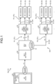
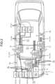
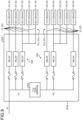
- a wire harness WH according to the present embodiment illustrated in FIGS. 1 and 2 is applied to a power supply system Sys mounted on a vehicle V.
- the power supply system Sys is a system that supplies power to various devices D mounted on the vehicle V.
- the devices D are load devices that operate and are driven by power supplied from the power supply system Sys to exhibit various functions in the vehicle V.
- the wire harness WH of the present embodiment achieves, in a situation where the devices D with different drive voltages are mixed, a configuration in which power can be appropriately supplied to the various devices D mounted on the vehicle V.
- each configuration of the wire harness WH and the like will be described in detail with reference to each drawing.
- the device D is a plurality of devices D with different drive voltages and includes a first device D1 driven at a first voltage V1 and a second device D2 driven at a second voltage V2.
- the first voltage V1 is, for example, a voltage of 30 V or more and 60 V or less.
- the second voltage V2 is lower than the first voltage V1, and is for example, higher than 0 V and lower than 30 V.
- description will be given on the assumption that the first voltage V1 is "48 V" and the second voltage V2 is "12 V".
- the first device D1 is a 48 V drive device driven at a voltage of 48 Vn
- the second device D2 is a 12 V drive device driven at a voltage of 12 V.
- the device D in a case where it is not necessary to particularly distinguish between the first device D1 and the second device D2, they are sometimes simply referred to as the "device D".
- the high-voltage battery B1 is a battery that stores power at a predetermined high voltage, and is a first power supply capable of supplying power at the predetermined high voltage.
- the high-voltage battery B1 typically has a voltage higher than that of the 48 V battery B2 and has, for example, a voltage (battery voltage) of about 300 V to 400 V.
- the high-voltage battery B1 of the present embodiment is electrically connected to the 48 V battery B2 via a DC/DC converter B1A, and supplies power to the 48 V battery B2.
- the DC/DC converter B1A is a transformer that converts a voltage of DC power.
- the 48 V battery B2 is a battery that stores power at the first voltage V1 lower than the voltage of the high-voltage battery B1, and is a second power supply capable of supplying power at the first voltage V1.
- the first voltage V1 is "48 V". That is, the 48 V battery B2 is a voltage (battery voltage) of about 48 V.
- the 48 V battery B2 is electrically connected to the high-voltage battery B1 via the DC/DC converter B1A, and can be charged with power supplied from the high-voltage battery B1 via the DC/DC converter B1A.
- the 48 V battery B2 is not limited to the high-voltage battery B1, and may be charged with power generated by, for example, a 48 V generator (48 V alternator) (not illustrated) or the like.
- the 48 V battery B2 is electrically connected to each device D via the wire harness WH, and supplies power to each device D via the wire harness WH.
- the 48 V battery B2 of the present embodiment serves as a power supply that supplies power to both the first device D1 and the second device D2 via the wire harness WH.
- the wire harness WH constitutes a power supply system PL that supplies power from the 48 V battery B2, which is the power supply, to each device D.
- the wire harness WH of the present embodiment has a voltage conversion function of converting the voltage of the power supplied from the 48 V battery B2 into the second voltage V2, which is lower than the first voltage V1, to output the second voltage V2. Thereby, power is appropriately supplied to the first device D1 and the second device D2 with different drive voltages from each other.
- the wire harness WH of the present embodiment includes an electronic component unit 10, a power supply wire 20, a 48 V power supply distribution BOX 30, and a 12 V power supply distribution BOX 40.
- the electronic component unit 10 is equipped with the voltage conversion function.
- the electronic component unit 10 is a unit directly connected to the 48 V battery B2 that is a power supply, and may be referred to as a battery fuse terminal (BFT).
- BFT battery fuse terminal
- the electronic component unit 10 of the present embodiment further has the voltage conversion function for outputting 12 V in addition to a circuit branch function and a circuit protection function.
- the configuration enables the electronic component unit 10 to distribute power to the second device D2 that is the 12 V drive device in addition to distributing power to the first device D1 that is the 48 V drive device.
- the 48 V battery B2 provided with the electronic component unit 10 includes a battery housing B2a and a battery post B2b.
- the battery housing B2a is formed in a substantially rectangular parallelepiped shape as a whole, and houses battery liquid and various components therein.
- the battery post B2b is provided to protrude from the upper surface of the battery housing B2a.
- the battery post B2b is made of conductive lead or the like to have a substantially cylindrical shape.
- a pair of battery posts B2b is provided on the upper surface of the battery housing B2a at intervals, and one of the battery posts B2b constitutes an anode and the other constitutes a cathode.
- the electronic component unit 10 of the present embodiment is assembled to the battery post B2b on the anode side.
- the electronic component unit 10 includes a battery terminal 11 functioning as a power supply terminal and a unit body 12, and is electrically connected to the battery post B2b on the anode side via the battery terminal 11.
- circuit branch portion 13 In a state where the circuit branch portion 13 is embedded in the housing 16, a part of the circuit branch portion 13 located in the base portion 12A is partially exposed and a fastening hole 13a is formed in the exposed part.
- the stud bolt 11b described above is inserted through the fastening hole 13a to be screwed into the nut 11c, so that the circuit branch portion 13 is fastened to the battery terminal 11, electrically connected to the battery terminal 11, and electrical contact can be made.
- the circuit branch portion 13 is conducted to the 48 V battery B2 via the battery terminal 11, and power is supplied and input from the 48 V battery B2 at the first voltage V1, that is, at a voltage of 48 V.
- the voltage converter 15 is provided in at least one of the plurality of power supply systems PL in the circuit branch portion 13.
- the voltage converter 15 converts a voltage of the power supplied from the 48 V battery B2 into the second voltage V2 lower than the first voltage V1 to output the second voltage V2.
- the electronic component unit 10 of the present embodiment can also output at the second voltage V2 lower than the first voltage V1 in addition to the output at the first voltage V1 corresponding to the battery voltage of the 48 V battery B2.
- the voltage converter 15 is provided in the 12 V power supply system PL2 of the plurality of power supply systems PL in the circuit branch portion 13.
- the voltage converter 15 performs step-down voltage conversion on a voltage of 48 V corresponding to the first voltage V1 into a voltage of 12 V corresponding to the second voltage V2 to output the voltage of 12 V to the 12 V power supply system PL2.
- the voltage converter 15 is typically configured with a DC/DC converter that converts a voltage of DC power.
- the voltage converter 15 may be configured to be directly incorporated into a portion constituting the 12 V power supply system PL2 in the circuit branch portion 13 by soldering or the like.
- the voltage converter 15 may be configured to be detachable from the 12 V power supply system PL2 in the circuit branch portion 13 by accommodating a converter body 15A in which the electronic components are mounted on the substrate in a housing 15B and modularizing a configuration in which a connection terminal 15C protrudes from the housing 15B.
- the voltage converter 15 is detachably assembled to the circuit branch portion 13 by inserting the connection terminal 15C into a portion constituting the 12 V power supply system PL2 in the circuit branch portion 13.
- the circuit protector 14 descried above may be disposed on the upstream side of the voltage converter 15 (48 V battery B2 side) and configured to be integrated with the voltage converter 15, or, alternatively, may be disposed on the downstream side of the voltage converter 15 (second device D2 side) and configured to be integrated with the voltage converter 15.
- the electronic component unit 10 configured as described above outputs a part of the power input from the 48 V battery B2 to the circuit branch portion 13 via the battery terminal 11 to each 48 V power supply system PL1 at the first voltage V1 corresponding to the battery voltage without transforming the part of the power, and steps down the remaining part of the power to the second voltage V2 by the voltage converter 15 to output the second voltage V2 to the 12 V power supply system PL2.
- the electronic component unit 10 outputs power at a voltage of 48 V corresponding to the first voltage V1 to the first device D1 that is the 48 V drive device, and outputs power at a voltage of 12 V corresponding to the second voltage V2 to the second device D2 that is the 12 V drive device.
- the electronic component unit 10 protects each power supply system PL by interposing the circuit protector 14 in each power supply system PL in the circuit branch portion 13.
- the power supply wire 20 is a wiring member that is interposed between the electronic component unit 10 and the device D to supply power from the electronic component unit 10 to the device D. That is, the power supply wire 20 constitutes the power supply system PL that supplies power to the device D.
- the power supply wire 20 is typically configured with a general electric wire, but may be configured with, for example, a planar circuit body such as a flexible printed circuit (FPC) or a flexible flat cable (FFC).
- the power supply wire 20 of the present embodiment includes a first power supply wire 21 and a second power supply wire 22.
- the 48 V power supply distribution BOX 30 distributes power output at a voltage of 48 V corresponding to the first voltage V1 without being stepped down in the electronic component unit 10 to the plurality of first devices D1 that are the 48 V drive devices.
- the first power supply wire 21 branches, on the output side of the 48 V power supply distribution BOX 30, into the number corresponding to the number of first devices D1 to which power is distributed from the 48 V power supply distribution BOX 30.
- a total of three 48 V power supply distribution BOXES 30 are illustrated.
- the 12 V power supply distribution BOX 40 is interposed between the electronic component unit 10 and the second device D2, and distributes the power supplied from the 48 V battery B2 to the plurality of second devices D2.
- the 12 V power supply distribution BOX 40 includes electronic components such as a branch portion, a fuse (circuit protector), and a relay, and distributes power to the plurality of second devices D2 in cooperation of these electronic components.
- the 12 V power supply distribution BOX 40 is provided on the second power supply wire 22 constituting the 12 V power supply system PL2 of the power supply system PL.
- the 12 V power supply distribution BOX 40 distributes power stepped down by the voltage converter 15 in the electronic component unit 10 and output at a voltage of 12 V corresponding to the second voltage V2 to the plurality of second devices D2 that are the 12 V drive devices.
- the second power supply wire 22 branches, on the output side of the 12 V power supply distribution BOX 40, into the number corresponding to the number of second devices D2 to which power is distributed from the 12 V power supply distribution BOX 40. In the example of FIG. 2 , a total of one 12 V power supply distribution BOX 40 is illustrated.
- the wire harness WH and the electronic component unit 10 described above can output, in the electronic component unit 10, a part of the power input from the 48 V battery B2 to the circuit branch portion 13 via the battery terminal 11 without being transformed to each of the 48 V power supply systems PL1 at the first voltage V1 corresponding to the battery voltage.
- the wire harness WH and the electronic component unit 10 can step down, in the electronic component unit 10, the remaining part of the power input from the 48 V battery B2 to the circuit branch portion 13 via the battery terminal 11 to the second voltage V2 by the voltage converter 15 and output the second voltage V2 to the 12 V power supply system PL2.
- the electronic component unit 10 can output power at a voltage of 48 V corresponding to the first voltage V1 to the first device D1 that is the 48 V drive device, and output power at a voltage of 12 V corresponding to the second voltage V2 lower than the first voltage V1 to the second device D2 that is the 12 V drive device.
- the wire harness WH and the electronic component unit 10 can appropriately distribute and supply power to the first device D1 and the second device D2 with different drive voltages from each other.
- the wire harness WH is disposed such that the electronic component unit 10 having the voltage conversion function of transforming from the first voltage V1 corresponding to the battery voltage of the 48 V battery B2 to the second voltage V2 and outputting the second voltage V2 is directly provided on the 48 V battery B2.
- the wire harness WH and the electronic component unit 10 for example, in a case where the second devices D2 driven at the second voltage V2 are densely disposed in the vicinity of the 48 V battery B2, the routing length of the second power supply wire 22 whose wire diameter is relatively large and whose weight tends to be large can be shortened as much as possible to enhance the routing efficiency. This prevents the weight of the entire wire harness WH from being increased.
- the circuit protector 14 is interposed in each power supply system PL in the circuit branch portion 13 of the electronic component unit 10. Thus, when overcurrent flows through the power supply system PL, the circuit protector 14 cuts off the overcurrent, so that the power supply system PL can be protected.
- the voltage converter 15 can be configured to be detachable from the power supply system PL in the circuit branch portion 13.
- the voltage converter 15 can be appropriately changed and added according to necessary performance in a case where a new device D is additionally mounted during use while the vehicle V tends to be used for a long period of time to achieve carbon neutral or the like.
- the voltage converter 15 is selected according to addition or update of the device D mounted on the vehicle V and assembled to the electronic component unit 10, so that it is possible to easily achieve necessary voltage output and capacity without replacing the entire electronic component unit 10 with another one, for example.
- the number of outputs of the second voltage V2 lower than the first voltage V1, which is a battery voltage can be optionally increased according to the situation by providing, in each power supply system PL, a structure that the voltage converter 15 is detachable, for example, in the circuit branch portion 13.
- the electronic component unit 10 has the circuit protection function together with the circuit branch function and the voltage conversion function, but the present invention is not limited thereto. Specifically, it is possible that the electronic component unit 10 does not include the circuit protector 14 and, for example, the circuit protector may be provided in another part on each power supply system PL.
- the circuit branch portion 13 branches the power supplied from the 48 V battery B2 into the plurality of 48 V power supply systems PL1 and one 12 V power supply system PL2, but the present invention is not limited thereto. Two or more 12 V power supply systems PL2 may be provided. In this case, in the electronic component unit 10, the voltage converter 15 is provided in each 12 V power supply system PL2 in the circuit branch portion 13.
- the power supply terminal 11 and the unit body 12 are configured separately, but the present invention is not limited thereto.
- the power supply terminal 11 and the unit body 12 may be integrally configured, and for example, the power supply terminal 11 and the circuit branch portion 13 may be integrally connected.
- the electronic component unit and the wire harness according to the present embodiment may be configured by appropriately combining the constituent elements of the embodiment and the modifications described above.
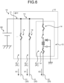
- FIGS. 8 and 9 illustrate a schematic configuration of a power supply system SysA to which a wire harness WHA according to a reference example is applied.
- the wire harness WHA according to the reference example is different from the wire harness WH described above in that the wire harness WHA includes an electronic component unit 10A instead of the electronic component unit 10 and includes a power supply distribution BOX 50A instead of the 48 V power supply distribution BOX 30 and the 12 V power supply distribution BOX 40.
- the electronic component unit 10A according to the reference example is different from the electronic component unit 10 described above in that the electronic component unit 10A does not have the voltage converter 15 implementing the voltage conversion function.
- the other configurations of the wire harness WHA and the electronic component unit 10A are substantially similar to those of the wire harness WH and the electronic component unit 10.
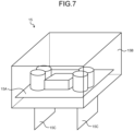
- the power supply distribution BOX 50A includes a 48 V power supply distributor 30A, a 12 V power supply distributor 40A, and a voltage converter 60A, which are unitized in one housing (BOX) 50Aa. Thereby, the voltage conversion function for outputting 12 V corresponding to the second voltage V2 is implemented.
- the 48 V power supply distributor 30A is interposed between the electronic component unit 10A and the first device D1, and distributes the power supplied from the 48 V battery B2 to the plurality of first devices D1.
- the 48 V power supply distributor 30A includes electronic components such as a branch portion, a fuse (circuit protector), and a relay, and distributes power to the plurality of first devices D1 in cooperation of these electronic components.
- the 48 V power supply distributor 30A is provided on the first power supply wire 21 constituting the 48 V power supply system PL1 of the power supply system PL.
- the 48 V power supply distributor 30A distributes power output at a voltage of 48 V corresponding to the first voltage V1 without being stepped down in the electronic component unit 10A to the plurality of first devices D1 that are the 48 V drive devices.
- the first power supply wire 21 branches, on the output side of the 48 V power supply distributor 30A, into the number corresponding to the number of first devices D1 to which power is distributed from the 48 V power supply distributor 30A.
- the voltage converter 60A converts the voltage of the power branched and supplied from the 48 V power supply distributor 30A into the second voltage V2 lower than the first voltage V1 to output the second voltage V2, and outputs the second voltage V2 to the 12 V power supply distributor 40A.
- the power supply distribution BOX 50A of the reference example can also output at the second voltage V2 lower than the first voltage V1 in addition to the output at the first voltage V1 corresponding to the battery voltage of the 48 V battery B2.
- the voltage converter 60A is interposed between the 48 V power supply distributor 30A and the 12 V power supply distributor 40A in the circuit in the power supply distribution BOX 50A.
- the voltage converter 60A performs step-down voltage conversion on a voltage of 48 V corresponding to the first voltage V1 into a voltage of 12 V corresponding to the second voltage V2 to output the voltage of 12 V to the 12 V power supply distributor 40A.
- the voltage converter 60A is typically configured with a DC/DC converter that converts a voltage of DC power.
- the 12 V power supply distributor 40A is interposed between the electronic component unit 10A and the second device D2, and distributes the power supplied from the 48 V battery B2 to the plurality of second devices D2.
- the 12 V power supply distributor 40A includes electronic components such as a branch portion, a fuse (circuit protector), and a relay, and distributes power to the plurality of second devices D2 in cooperation of these electronic components.
- the 12 V power supply distributor 40A of the reference example distributes power stepped down by the voltage converter 60A in the power supply distribution BOX 50A and output at a voltage of 12 V corresponding to the second voltage V2 to the plurality of second devices D2 that are the 12 V drive devices.
- a portion of the power supply system PL closer to the second device D2 side than the 12 V power supply distributor 40A constitutes the 12 V power supply system PL2.
- the second power supply wire 22 branches, on the output side of the 12 V power supply distributor 40A, into the number corresponding to the number of second devices D2 to which power is distributed from the 12 V power supply distributor 40A.
- the 48 V power supply distributor 30A that distributes power supply of a voltage of 48 V corresponding to the first voltage V1
- the voltage converter 60A that performs voltage conversion from the first voltage V1 to the second voltage V2
- the 12 V power supply distributor 40A that distributes power supply of a voltage of 12 V corresponding to the second voltage V2 can be unitized in one housing 50Aa.
- the wire harness WHA and the power supply system SysA according to the reference example can appropriately supply power to the various devices D mounted on the vehicle V while preventing an increase in types of metal molds required to mold various casings used in the wire harness WHA, for example.
- the power supply distribution BOX 50A may include a zone ECU and the like in the vehicle V together with the 48 V power supply distributor 30A, the 12 V power supply distributor 40A, the voltage converter 60A, and the like.
- the voltage converter 15 can be appropriately changed and added according to necessary performance, for example, in a case where a new device D is additionally mounted while the wire harness WH and the electronic component unit 10 are used.
- the wire harness and the electronic component unit may have a configuration in which the voltage converter is removed, for example, in a case where the voltage converter 15 becomes unnecessary afterwards.
- the electronic component unit and the wire harness according to the present embodiment exhibit advantageous effects of appropriately supplying power to various devices mounted on a vehicle.
Landscapes
- Engineering & Computer Science (AREA)
- Mechanical Engineering (AREA)
- Power Engineering (AREA)
- Direct Current Feeding And Distribution (AREA)
- Charge And Discharge Circuits For Batteries Or The Like (AREA)
- Emergency Protection Circuit Devices (AREA)
Applications Claiming Priority (1)
| Application Number | Priority Date | Filing Date | Title |
|---|---|---|---|
| JP2023148046A JP7772756B2 (ja) | 2023-09-13 | 2023-09-13 | 電子部品ユニット、及び、ワイヤハーネス |
Publications (1)
| Publication Number | Publication Date |
|---|---|
| EP4523974A1 true EP4523974A1 (de) | 2025-03-19 |
Family
ID=92672146
Family Applications (1)
| Application Number | Title | Priority Date | Filing Date |
|---|---|---|---|
| EP24198134.9A Pending EP4523974A1 (de) | 2023-09-13 | 2024-09-03 | Elektronische komponenteneinheit und kabelbaum |
Country Status (4)
| Country | Link |
|---|---|
| US (1) | US20250083620A1 (de) |
| EP (1) | EP4523974A1 (de) |
| JP (1) | JP7772756B2 (de) |
| CN (1) | CN119611242A (de) |
Citations (5)
| Publication number | Priority date | Publication date | Assignee | Title |
|---|---|---|---|---|
| US6775119B2 (en) * | 2001-08-07 | 2004-08-10 | Yazaki Corporation | Electrical connection system for vehicle |
| US20050230160A1 (en) * | 2004-04-14 | 2005-10-20 | Toyota Jidosha Kabushiki Kaisha | Power supply apparatus for vehicle |
| DE102011075091A1 (de) * | 2011-05-02 | 2012-11-08 | Continental Automotive Gmbh | Elektrochemischer Energiespeicher für ein Fahrzeug sowie Verwendung eines elektrochemischen Energiespeichers für ein Fahrzeug |
| JP2016222085A (ja) | 2015-05-29 | 2016-12-28 | 矢崎総業株式会社 | ワイヤハーネス |
| US10889203B2 (en) * | 2018-03-26 | 2021-01-12 | Volvo Car Corporation | Vehicle power supply system with redundancy and method for controlling the power supply system |
Family Cites Families (3)
| Publication number | Priority date | Publication date | Assignee | Title |
|---|---|---|---|---|
| JP2000318545A (ja) | 1999-05-12 | 2000-11-21 | Yazaki Corp | 車両用配電函及び車両用配電システム |
| US10391957B2 (en) | 2016-04-05 | 2019-08-27 | Ford Global Technologies, Llc | Integrated power distribution system for a vehicle |
| JP6809855B2 (ja) * | 2016-09-27 | 2021-01-06 | 古河電気工業株式会社 | 電気接続箱 |
-
2023
- 2023-09-13 JP JP2023148046A patent/JP7772756B2/ja active Active
-
2024
- 2024-09-03 EP EP24198134.9A patent/EP4523974A1/de active Pending
- 2024-09-06 US US18/827,658 patent/US20250083620A1/en active Pending
- 2024-09-12 CN CN202411274690.XA patent/CN119611242A/zh active Pending
Patent Citations (5)
| Publication number | Priority date | Publication date | Assignee | Title |
|---|---|---|---|---|
| US6775119B2 (en) * | 2001-08-07 | 2004-08-10 | Yazaki Corporation | Electrical connection system for vehicle |
| US20050230160A1 (en) * | 2004-04-14 | 2005-10-20 | Toyota Jidosha Kabushiki Kaisha | Power supply apparatus for vehicle |
| DE102011075091A1 (de) * | 2011-05-02 | 2012-11-08 | Continental Automotive Gmbh | Elektrochemischer Energiespeicher für ein Fahrzeug sowie Verwendung eines elektrochemischen Energiespeichers für ein Fahrzeug |
| JP2016222085A (ja) | 2015-05-29 | 2016-12-28 | 矢崎総業株式会社 | ワイヤハーネス |
| US10889203B2 (en) * | 2018-03-26 | 2021-01-12 | Volvo Car Corporation | Vehicle power supply system with redundancy and method for controlling the power supply system |
Also Published As
| Publication number | Publication date |
|---|---|
| CN119611242A (zh) | 2025-03-14 |
| JP7772756B2 (ja) | 2025-11-18 |
| US20250083620A1 (en) | 2025-03-13 |
| JP2025041005A (ja) | 2025-03-26 |
Similar Documents
| Publication | Publication Date | Title |
|---|---|---|
| US7549872B2 (en) | Electric junction box | |
| US9197048B2 (en) | High-voltage electrical junction box | |
| US8471670B2 (en) | Fusible link unit | |
| EP0884750A2 (de) | Schmelzsicherungsanordnung | |
| US20130095696A1 (en) | Fuse unit | |
| EP0906853A2 (de) | Verbindungskasten montiert auf einer Batterie | |
| CN110979207A (zh) | 线束 | |
| EP4523972A1 (de) | Kabelbaum | |
| US10381184B1 (en) | Multiple-use interlocking fused power and grounding distribution block | |
| EP4523974A1 (de) | Elektronische komponenteneinheit und kabelbaum | |
| EP4523975B1 (de) | Elektronische komponenteneinheit und kabelbaum | |
| JP6424066B2 (ja) | スイッチボックス | |
| JP7188926B2 (ja) | 車両用電力分配システム | |
| US10931071B2 (en) | Wiring module and connection member for wiring module | |
| JP6424065B2 (ja) | スイッチボックス | |
| JPH11299115A (ja) | 車両用バッテリボックス | |
| JP7144150B2 (ja) | 車載電源分配装置 | |
| US11081814B2 (en) | Wiring module | |
| JP7410113B2 (ja) | 電気接続ユニット | |
| JPH10241547A (ja) | ジャンクションボックス | |
| JP7495255B2 (ja) | 電気接続箱 | |
| CN220884058U (zh) | 车辆电源线束系统及车辆 | |
| JP2019193442A (ja) | 電気接続箱 | |
| JPH0970120A (ja) | 電気接続箱 | |
| JP2023087765A (ja) | 電気接続箱およびワイヤハーネス |
Legal Events
| Date | Code | Title | Description |
|---|---|---|---|
| PUAI | Public reference made under article 153(3) epc to a published international application that has entered the european phase |
Free format text: ORIGINAL CODE: 0009012 |
|
| STAA | Information on the status of an ep patent application or granted ep patent |
Free format text: STATUS: REQUEST FOR EXAMINATION WAS MADE |
|
| 17P | Request for examination filed |
Effective date: 20240903 |
|
| AK | Designated contracting states |
Kind code of ref document: A1 Designated state(s): AL AT BE BG CH CY CZ DE DK EE ES FI FR GB GR HR HU IE IS IT LI LT LU LV MC ME MK MT NL NO PL PT RO RS SE SI SK SM TR |