EP4521384A1 - Stützelement, verfahren zur herstellung eines stützelements und anzeigemodul und elektronische vorrichtung - Google Patents
Stützelement, verfahren zur herstellung eines stützelements und anzeigemodul und elektronische vorrichtung Download PDFInfo
- Publication number
- EP4521384A1 EP4521384A1 EP23826410.5A EP23826410A EP4521384A1 EP 4521384 A1 EP4521384 A1 EP 4521384A1 EP 23826410 A EP23826410 A EP 23826410A EP 4521384 A1 EP4521384 A1 EP 4521384A1
- Authority
- EP
- European Patent Office
- Prior art keywords
- support member
- filling material
- bendable
- display
- hole
- Prior art date
- Legal status (The legal status is an assumption and is not a legal conclusion. Google has not performed a legal analysis and makes no representation as to the accuracy of the status listed.)
- Pending
Links
Images


Classifications
-
- G—PHYSICS
- G09—EDUCATION; CRYPTOGRAPHY; DISPLAY; ADVERTISING; SEALS
- G09F—DISPLAYING; ADVERTISING; SIGNS; LABELS OR NAME-PLATES; SEALS
- G09F9/00—Indicating arrangements for variable information in which the information is built-up on a support by selection or combination of individual elements
- G09F9/30—Indicating arrangements for variable information in which the information is built-up on a support by selection or combination of individual elements in which the desired character or characters are formed by combining individual elements
- G09F9/301—Indicating arrangements for variable information in which the information is built-up on a support by selection or combination of individual elements in which the desired character or characters are formed by combining individual elements flexible foldable or roll-able electronic displays, e.g. thin LCD, OLED
-
- H—ELECTRICITY
- H05—ELECTRIC TECHNIQUES NOT OTHERWISE PROVIDED FOR
- H05K—PRINTED CIRCUITS; CASINGS OR CONSTRUCTIONAL DETAILS OF ELECTRIC APPARATUS; MANUFACTURE OF ASSEMBLAGES OF ELECTRICAL COMPONENTS
- H05K5/00—Casings, cabinets or drawers for electric apparatus
- H05K5/02—Details
- H05K5/0217—Mechanical details of casings
-
- G—PHYSICS
- G06—COMPUTING OR CALCULATING; COUNTING
- G06F—ELECTRIC DIGITAL DATA PROCESSING
- G06F1/00—Details not covered by groups G06F3/00 - G06F13/00 and G06F21/00
- G06F1/16—Constructional details or arrangements
- G06F1/1613—Constructional details or arrangements for portable computers
- G06F1/1633—Constructional details or arrangements of portable computers not specific to the type of enclosures covered by groups G06F1/1615 - G06F1/1626
- G06F1/1637—Details related to the display arrangement, including those related to the mounting of the display in the housing
- G06F1/1641—Details related to the display arrangement, including those related to the mounting of the display in the housing the display being formed by a plurality of foldable display components
-
- G—PHYSICS
- G06—COMPUTING OR CALCULATING; COUNTING
- G06F—ELECTRIC DIGITAL DATA PROCESSING
- G06F1/00—Details not covered by groups G06F3/00 - G06F13/00 and G06F21/00
- G06F1/16—Constructional details or arrangements
- G06F1/1613—Constructional details or arrangements for portable computers
- G06F1/1633—Constructional details or arrangements of portable computers not specific to the type of enclosures covered by groups G06F1/1615 - G06F1/1626
- G06F1/1637—Details related to the display arrangement, including those related to the mounting of the display in the housing
- G06F1/1652—Details related to the display arrangement, including those related to the mounting of the display in the housing the display being flexible, e.g. mimicking a sheet of paper, or rollable
-
- G—PHYSICS
- G06—COMPUTING OR CALCULATING; COUNTING
- G06F—ELECTRIC DIGITAL DATA PROCESSING
- G06F1/00—Details not covered by groups G06F3/00 - G06F13/00 and G06F21/00
- G06F1/16—Constructional details or arrangements
- G06F1/1613—Constructional details or arrangements for portable computers
- G06F1/1633—Constructional details or arrangements of portable computers not specific to the type of enclosures covered by groups G06F1/1615 - G06F1/1626
- G06F1/1675—Miscellaneous details related to the relative movement between the different enclosures or enclosure parts
- G06F1/1681—Details related solely to hinges
Definitions
- Embodiments of this application relate to the display field, and in particular, to a support member, a method for manufacturing a support member, a display module, and an electronic device.
- an electronic device gradually becomes a development trend of a future mobile electronic product.
- a large display area can be provided, improving video watching effect.
- a small volume can be provided, bringing convenience of carrying for a user.
- the electronic device includes at least a flexible display and a support member for bearing the flexible display.
- the flexible display includes a bendable portion, and a through hole is provided on a region that is of the support member and that corresponds to the bendable portion, to improve bending performance of the support member.
- Embodiments of this application provide a support member, a method for manufacturing a support member, a display module, and an electronic device, to resolve problems of poor anti-extrusion performance and anti-impact performance of an existing electronic device.
- a support member is provided.
- the support member is configured to support a display.
- the display includes a first unbendable portion, a second unbendable portion, and a bendable portion.
- the support member includes a first support member opposite to the first unbendable portion, a second support member opposite to the second unbendable portion, and a bendable support member opposite to the bendable portion.
- the bendable support member is located between the first support member and the second support member.
- the bendable support member includes a first surface opposite to the bendable portion and a second surface opposite to the first surface.
- One or more through holes are provided on the bendable support member. The through hole penetrates through the first surface and the second surface of the bendable support member.
- the through hole is filled with a filling material.
- a thickness of the filling material is less than or equal to a thickness of the support member.
- An elastic modulus of the filling material is less than an elastic modulus of the support member. Therefore, the filling material is disposed in the through hole of the support member, to improve anti-impact performance and anti-extrusion performance of an electronic device.
- the elastic modulus of the filling material is less than the elastic modulus of the support member. When the filling material is compressed or stretched, deformation of the filling material is greater than deformation of the support member.
- the filling material is disposed in the through hole of the support member, to help further improve bending performance of a bendable region of the support member.
- the filling material is filled into the through hole in an inkjet printing manner. Therefore, a filling manner of the inkjet printing can implement patterned coating, and has advantages of high printing precision and good uniformity of a printed filling material.
- the filling material includes at least one of a filling adhesive, resin, and a polymer material. In this way, an optional material of the filling material is more diversified.
- the filling adhesive includes at least one of a photosensitive adhesive, a thermosetting adhesive, and a moisture-curing adhesive. In this way, an optional material of the filling adhesive is more diversified.
- the filling material is in a strip shape.
- a length direction of the filling material is parallel to a length direction of the bendable portion. Therefore, the anti-extrusion performance of the support member can be improved.
- the filling material further includes a first limiting portion.
- the first limiting portion is disposed on at least one end of the filling material in the length direction.
- the first limiting portion is snap-fitted to the through hole. Therefore, the first limiting portion may change stress distribution on the support member.
- the filling material further includes a second limiting portion.
- the second limiting portion is disposed on at least one end of the filling material in a thickness direction.
- the second limiting portion is snap-fitted to the through hole. In this way, the second limiting portion may prevent the filling material from being extruded out during use.
- the filling material meets at least one of the following conditions: a Young's modulus is greater than 1 MPa; a glass transition temperature is less than 0°C; a stress relaxation recovery rate is greater than 90%; and an elastic limit is greater than 50%. Therefore, the filling material is disposed in the through hole of the support member, to help improve the anti-extrusion performance and the anti-impact performance of the support member.
- a material of the support member includes at least one of a fiber, a pure metal, and an alloy. Therefore, the anti-extrusion performance and the anti-impact performance of the support member can be improved.
- a method for manufacturing a support member is provided.
- the support member is configured to support a display.
- the display includes a first unbendable portion, a second unbendable portion, and a bendable portion.
- the support member includes a first support member opposite to the first unbendable portion, a second support member opposite to the second unbendable portion, and a bendable support member opposite to the bendable portion.
- the bendable support member is located between the first support member and the second support member.
- the method includes: filling a filling material into a through hole of the bendable support member in an inkjet printing manner, where the bendable support member includes a first surface opposite to the bendable portion and a second surface opposite to the first surface, one or more through holes are provided on the bendable support member, and the through hole penetrates through the first surface and the second surface of the bendable support member; and curing the filling material, where a height of the filling material is less than or equal to a height of the through hole, and an elastic modulus of the filling material is less than an elastic modulus of the support member. Therefore, a filling manner of the inkjet printing can implement patterned coating, and has advantages of high printing precision and good uniformity of a printed filling material.
- the filling a filling material into a through hole of the support member in an inkjet printing manner includes: attaching a bearing layer to one surface of the support member; and performing inkjet printing on a surface that is of the support member and that is away from the bearing layer, and filling the filling material into the through hole of the support member.
- the bearing layer may be a release film or a display.
- the bearing layer is the release film. After the curing the filling material, the method further includes: removing the bearing layer.
- the bearing layer is the display.
- the display may not need to be removed, so that the display is connected to a support layer through the filling material.
- a display module including a display and the foregoing support member.
- the display includes a display panel and a cover plate that are disposed in a stacked manner. A backlight surface of the display panel is close to the support member.
- the cover plate is disposed on a light-emitting surface of the display panel. Therefore, the display module uses the foregoing support member, so that anti-impact performance and anti-extrusion performance of the display module are improved.
- a protective film is disposed on a side that is of the cover plate and that is away from the display panel. Therefore, the protective film may protect the display.
- an electronic device including a housing and the display module described above.
- the housing is disposed on a side that is of the support member and that is away from the display. Therefore, the electronic device uses the foregoing display module, so that anti-impact performance and anti-extrusion performance of the electronic device are improved.
- Embodiments of this application provide the support member, the method for manufacturing the support member, the display module, and the electronic device.
- the filling material is disposed in the through hole in the bendable region of the support member, to improve the anti-impact performance and the anti-extrusion performance of the electronic device.
- the elastic modulus of the filling material is less than the elastic modulus of the support member. When the filling material is compressed or stretched, the deformation of the filling material is greater than the deformation of the support member.
- the filling material is disposed in the through hole of the support member, to help further improve the bending performance of the bendable region of the support member.
- orientation terms such as “up” and “down” are defined relative to an orientation of a schematically placed component in the accompanying drawings. It should be understood that these direction terms are relative concepts and are used for relative description and clarification, and may vary correspondingly based on a change in an orientation in which the component is placed in the accompanying drawings.
- An embodiment of this application provides an electronic device.
- the electronic device may be a product having a display interface, such as a mobile phone, a display, a tablet computer, or an in-vehicle computer.
- a specific form of the electronic device is not specially limited in embodiments of this application.
- FIG. 1a is a diagram of a disassembling structure of an electronic device according to an embodiment of this application.
- the electronic device includes a display module 1, a middle frame 2, and a housing 3 (or referred to as a battery cover or a rear housing).
- the middle frame 2 is located between the display module 1 and the housing 3.
- the display module 1 is configured to display an image.
- a surface that is of the middle frame 2 and that is away from the display module 1 is configured to install an internal element such as a battery, a printed circuit board (printed circuit board, PCB), a camera (camera), or an antenna.
- an internal element such as a battery, a printed circuit board (printed circuit board, PCB), a camera (camera), or an antenna.
- the display module 1 may be electrically connected, through a flexible printed circuit (flexible printed circuit, FPC), to the PCB disposed on the middle frame 2. Therefore, the PCB can transmit display data to the display module 1, to control the display module 1 to display the image.
- FPC flexible printed circuit
- the display module 1, the middle frame 2, and the housing 3 may be respectively disposed at different layers in a thickness direction of the electronic device. These layers may be parallel to each other. A plane in which each layer is located may be referred to as an X-Y plane, and a direction perpendicular to the X-Y plane may be referred to as a Z direction. In other words, the display module 1, the middle frame 2, and the housing 3 may be distributed hierarchically in the Z direction.
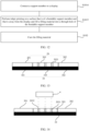
- FIG. 1b is a diagram of a structure of a display module according to an embodiment of this application.
- the display module includes a display 10 and a support member 20 configured to support the display 10.
- the display 10 includes a protective film 1003, a cover plate 1002, and a display panel 1001 that are disposed in a stacked manner in a Z direction.
- the support member 20 is disposed on a side that is of the display panel 1001 and that is away from the cover plate 1002. The support member 20 may support the display 10 and dissipate heat for the display 10.
- a structure of the display panel 1001 is not limited in this application.
- the display panel 1001 is an active matrix organic light emitting diode (active matrix organic light emitting diode, AMOLED) display.
- AMOLED active matrix organic light emitting diode
- the AMOLED display is a self-luminous display
- a back light module (back light module, BLM) is not required to be disposed in the AMOLED display. Therefore, when a substrate in the AMOLED display is made of a flexible resin material, for example, polyethylene terephthalate (polyethylene terephthalate, PET), the foregoing AMOLED display can have a bendable feature.
- the cover plate 1002 and the protective film 1003 may protect the display panel 1001, to avoid interference caused by an external environment to the display panel 1001.
- FIG. 2 is an A-A sectional view of FIG. 1b .
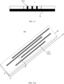
- FIG. 3 is a diagram of a disassembling structure of a display module according to an embodiment of this application.
- the support member 20 includes at least a first support member 201, a second support member 202, and a bendable support member 203.
- the display 10 is, for example, a flexible display.
- the display 10 includes: a first unbendable portion 101, a second unbendable portion 102, and a bendable portion 103.
- the bendable portion 103 is located between the first unbendable portion 101 and the second unbendable portion 102.
- the first support member 201 is connected to the first unbendable portion 101 of the display 10.
- the second support member 202 is connected to the second unbendable portion 102 of the display 10.
- the bendable support member 203 is connected to the bendable portion 103 of the display 10.
- the display 10 is in an unfolded state.
- the foregoing first support member 201 and the second support member 202 are configured to support the display 10 in a process of unfolding and folding the display 10, to ensure flatness of the display 10, and protect a non-display surface of the display 10.
- an extension direction of the through hole 2031 is perpendicular to a plane of the support member 20.
- an impact reliability test is performed on an electronic device, and it is found that the through hole is provided on a region that is of the support member and that corresponds to the bendable portion, consequently, anti-extrusion performance and anti-impact performance of a bendable portion region of the flexible display are poor, and a poor appearance phenomenon such as an orange peel texture, a mold print, or a crease of the bendable portion region occurs on the display, degrading user experience.
- FIG. 4 is a diagram of a structure of a support member according to an embodiment of this application.
- a support member 20 includes: a first support member 201, a second support member 202, a bendable support member 203, and a filling material 2032.
- the filling material 2032 is filled into a through hole 2031 of the bendable support member 203.
- the first support member 201 is configured to support a first unbendable portion of a display.
- the second support member 202 is configured to support a second unbendable portion of the display.
- the bendable support member is configured to support a bendable portion of the display.
- the bendable support member 203 is located between the first support member 201 and the second support member 202.
- a structure of the filling material 2032 is not limited in this embodiment of this application.
- the filling material 2032 should meet that an elastic modulus of the filling material 2032 is less than an elastic modulus of the support member 20.
- the elastic modulus of the filling material 2032 is greater than 1 MPa.
- a Young's modulus of the filling material 2032 may be represented by a Young's modulus E.
- ⁇ represents stress, and means a force applied to a unit cross-sectional area of the filling material 2032.
- ⁇ represents strain, and means an elongation amount corresponding to a unit length of the filling material 2032.
- a length of the filling material 2032 is L, and a cross-sectional area is S.
- a larger Young's modulus indicates that deformation of the filling material 2032 is smaller when the filling material 2032 is compressed or stretched.
- the filling material is disposed in the through hole of the support member 20, to help improve anti-extrusion performance and anti-impact performance of the support member 20.
- a glass transition temperature (glass transition temperature, Tg) of the filling material 2032 is less than 0°C. In some other embodiments of this application, the glass transition temperature of the filling material 2032 is, for example, less than -10°C.
- the glass transition temperature means a temperature corresponding to a change of the filling material 2032 from a glass state to a high elastic state.
- a lower Tg indicates a lower elastic modulus at a normal temperature, and a reliability gain is correspondingly reduced.
- An ambient temperature of the electronic device is usually greater than or equal to the glass transition temperature of the filling material 2032.
- the filling material 2032 in a normal use state, is in the high elastic state, so that the deformation is more likely to occur at the location of the through hole of the support member 20. This helps improve the bending performance of the support member 20.
- Stress relaxation recovery of the filling material 2032 is, for example, greater than 90%.
- the stress relaxation recovery means that stress of the filling material 2032 is reduced under a constant temperature and longterm constant strain, and unrecoverable plastic deformation is generated.
- An elastic limit of the filling material 2032 is, for example, greater than 50%.
- the elastic limit is a limit value of the deformation of the filling material 2032 under an external force. If the deformation of the filling material 2032 under the external force is less than the limit value, when the external force stops, the deformation of the filling material 2032 may totally disappear and the filling material 2032 is restored to an original state. If the deformation of the filling material 2032 under the external force exceeds the limit value, the filling material 2032 cannot be totally restored to an original state even if the external force is removed.
- the filling material 2032 provided in this embodiment of this application should meet at least one of the following conditions: the Young's modulus is greater than 1 Mpa, the glass transition temperature is less than 0°C, a stress relaxation recovery rate is greater than 90%, and the elastic limit is greater than 50%.
- a material of the support member is not limited in this embodiment of this application.
- the material of the support member includes at least one of a fiber, a pure metal, and an alloy, for example, a carbon fiber, stainless steel, an aluminum alloy, or a titanium alloy.
- a material of the filling material 2032 is not limited in this embodiment of this application.
- the filling material 2032 includes at least one of a filling adhesive, resin, and a polymer material.
- the filling adhesive includes at least one of a photosensitive adhesive, a thermosetting adhesive, and a moisture-curing adhesive, and in some embodiments, may alternatively be a mixed adhesive of two or more of them.
- the photosensitive adhesive may be, for example, an ultraviolet (Ultraviolet Light, UV) curing adhesive or an optical clear adhesive (Optical Clear Adhesive, OCA). Both the UV adhesive and the OCA adhesive have specific light curing performance, and the UV adhesive and the OCA adhesive are cured under light irradiation.
- UV Ultraviolet Light
- OCA optical Clear Adhesive
- thermosetting adhesive may be cured, for example, through heating.
- the moisture-curing adhesive may react with components such as water vapor and oxygen in air to complete curing.
- a thickness of the filling material 2032 is not limited in this embodiment of this application, and the thickness of the filling material 2032 is less than or equal to a thickness of the support member.
- the thickness of the support member is 50 ⁇ m to 300 ⁇ m.
- a molding manner of the filling material 2032 is not limited in this embodiment of this application. In some embodiments of this application, the filling material 2032 is filled into the through hole in an inkjet printing manner.
- An embodiment of this application further provides a method for manufacturing a support member.
- the support member is configured to support a display.
- the method for manufacturing the support member includes the following steps.
- S101 Fill a filling material into a through hole of a bendable support member in an inkjet printing manner.
- the display includes a first unbendable portion, a second unbendable portion, and a bendable portion.
- the support member includes a first support member opposite to the first unbendable portion, a second support member opposite to the second unbendable portion, and a bendable support member opposite to the bendable portion.
- the bendable support member is located between the first support member and the second support member.
- the bendable support member includes a first surface opposite to the bendable portion and a second surface opposite to the first surface.
- One or more through holes are provided on the bendable support member. The through hole penetrates through the first surface and the second surface of the bendable support member.
- the filling material is printer ink.
- an ultraviolet (Ultraviolet Light, UV) curing adhesive may be used, and a Young's modulus obtained by curing the UV curing adhesive is less than a Young's modulus of the support member.
- a filling manner of the inkjet printing can implement patterned coating, and has advantages of high printing precision and good uniformity of a printed filling material.
- An inkjet printing apparatus usually includes an ink cartridge and a nozzle capable of accurately depositing a solution in a design area.
- the nozzle may accurately spray the filling material (the printer ink) into the through hole of the support member.
- a spraying characteristic, solution volatilization behavior, ink viscosity and a nozzle diameter of the printer ink are important parameters that affect a resolution.
- the ink viscosity, surface tension, and density need to meet a black printing window shown in FIG. 6 , to implement adhesive spraying.
- Adhesive characteristics at the black printing window shown in FIG. 6 need to meet the following requirements: an adhesive Reynolds number Re: 100 ⁇ Re ⁇ 1000, and an adhesive Ohnesorge number Oh: 0.1 ⁇ Oh ⁇ 1.
- a height of the filling material is less than or equal to a height of the through hole, and a Young's modulus of a cured filling material is less than the Young's modulus of the support member.
- a bearing layer further needs to be attached to one surface of the bendable support member.
- Step S101 includes: performing the inkjet printing on a surface that is of the bendable support member and that is away from the bearing layer, and filling the filling material into the through hole of the bendable support member.
- a structure of the bearing layer is not limited in this embodiment of this application.
- the bearing layer uses a release film.
- filling the filling material into the through hole of the bendable support member in the inkjet printing manner includes the following steps.
- S1011 As shown in FIG. 8 , attach a release film 30 to one surface of a support member 20.
- the release film 30 includes a first surface and a second surface that are opposite to each other.
- an adhesive layer is disposed on the first surface of the release film 30, and the release film 30 may be bonded to the surface of the support member 20 through the adhesive layer.
- S1012 As shown in FIG. 9 , perform the inkjet printing on the surface that is of a bendable support member 203 and that is away from the release film. As shown in FIG. 10 , fill a filling material 2032 into a through hole 2031 of the bendable support member 203.
- the support member includes a first support member 201, a second support member 202, and a bendable support member 203 located between the first support member 201 and the second support member 202.
- the filling material 2032 is filled into the through hole 2031 of the bendable support member 203.
- step S102 the method further includes the following steps.
- the bearing layer may be a display.
- filling the filling material into the through hole of the support member in the inkjet printing manner includes the following steps.
- S1014 As shown in FIG. 13 , connect a support member 20 to a display 10.
- the display 10 is, for example, a flexible display.
- the display 10 includes a display surface and a non-display surface.
- the support member 20 is disposed close to the non-display surface of the display 10.
- the support member 20 may be bonded to the display 10 through the adhesive layer.
- the support member includes a first support member 201, a second support member 202, and a bendable support member 203 located between the first support member 201 and the second support member 202.
- the first support member 201 is configured to support a first unbendable portion 101 of the display 10.
- the second support member 202 is configured to support a second unbendable portion 102 of the display.
- the bendable support member 203 is configured to support a bendable portion 103 of the display.
- S1015 As shown in FIG. 14 , perform the inkjet printing on a surface that is of the bendable support member 203 and that is away from the display 10, and fill a filling material 2032 into a through hole 2031 of the bendable support member 203.
- the printer ink (the filling material 2032 in this application) may be accurately sprayed to the through hole 2031 of the bendable support member 203 by using an inkjet printer 4, to obtain a display module 1 shown in FIG. 15 .
- filling the filling material into the through hole of the support member in the inkjet printing manner can implement patterned coating, and has advantages of high printing precision and good uniformity of the printed filling material.
- impact reliability of the electronic device may be represented by a critical failure height of the electronic device.
- the critical failure height of the electronic device may be obtained by performing a sharp-head impact test on the electronic device by using an impact tester.
- the critical failure height of the electronic device means a falling height of a sharp head. When the falling height is exceeded, the electronic device is impacted and a broken bright spot is generated.
- the support member is made of the titanium alloy material, compared with a case in which no filling material is disposed in a through hole of the support member, after the filling material 1 is disposed in the through hole of the support member, the impact reliability of the electronic device is increased by 38%.
- the support member is made of the titanium alloy material, compared with a case in which no filling material is disposed in a through hole of the support member, after the filling material 2 is disposed in the through hole of the support member, the impact reliability of the electronic device is increased by 61%.
- the support member is made of the carbon fiber material, compared with a case in which no filling material is disposed in a through hole of the support member, after the filling material 1 is disposed in the through hole of the support member, the impact reliability of the electronic device is increased by 29%.
- the support member is made of the carbon fiber material, compared with a case in which no filling material is disposed in a through hole of the support member, after the filling material 2 is disposed in the through hole of the support member, the impact reliability of the electronic device is increased by 36%.
- anti-impact performance of the electronic device can be increased by more than 30%.
- the filling material is disposed in the through hole of the support member, to improve anti-impact performance and anti-extrusion performance of the electronic device.
- a Young's modulus of the filling material is less than a Young's modulus of the support member.
- deformation of the filling material is greater than deformation of the support member.
- the filling material is disposed in the through hole of the support member, to help further improve bending performance of a bendable region of the support member.
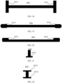
- FIG. 15a is a diagram of a structure of a bendable support member according to an embodiment of this application.
- FIG. 15b is a top view of the bendable support member in FIG. 15a .
- the filling material 2032 is of a strip shape structure, and a length direction of the filling material 2032 is parallel to a length direction of a bendable portion.
- a cross section shape of the filling material 2032 includes a straight line shape shown in FIG. 16 .
- the filling material further includes a first limiting portion 20321.
- the first limiting portion 20321 is disposed on at least one end of the filling material in a length direction.
- a longitudinal section size of the first limiting portion 20321 is greater than a longitudinal section size of the filling material.
- the first limiting portion is snap-fitted to the through hole. In this way, the first limiting portion 20321 may change stress distribution on the support member.
- the filling material 2032 includes one first limiting portion 20321, and a cross section shape of the filling material 2032 includes a T shape.
- the filling material 2032 includes two first limiting portions 20321, and a cross section shape of the filling material 2032 includes an I-shaped shape shown in FIG. 18 , and an hourglass shape shown in FIG. 19 and FIG. 20 .
- the filling material 2032 further includes a second limiting portion 20322.
- the second limiting portion 20322 is disposed on at least one end of the filling material 2032 in a thickness direction.
- a cross section size of the second limiting portion 20322 is greater than a cross section size of the filling material 2032.
- the second limiting portion is snap-fitted to the through hole.
- the second limiting portion 20322 may prevent the filling material 2032 from being extruded out during use.
- the filling material 2032 includes one second limiting portion 20322, and a longitudinal section shape of the filling material 2032 includes a T shape.
- the filling material 2032 includes two second limiting portions 20322, and a longitudinal section shape of the filling material 2032 includes an I-shaped shape shown in FIG. 22 and an hourglass shape shown in FIG. 23 and FIG. 24 .
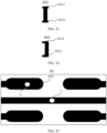
- the through hole is filled with the filling material 2032, and different locations of the filling material 2032 have different anti-impact capabilities.
- a location a is located in the first limiting portion 20321 of the filling material 2032, and a location b is located in the middle of the filling material 2032.
- the impact test is performed on different locations of the electronic device. Impact test results of regions corresponding to the location a and the location b in FIG. 25 in the electronic device are shown in Table 2.
- Table 2 Whether a filling material is disposed in a through hole Critical failure height for sharp head impact of an electronic device at a location a Critical failure height for sharp head impact of an electronic device at a location b
- No filling material 108 74.1 Have a filling material 119 101
- the critical failure height of the electronic device is 74.1 mm; and when there is the filling material in the through hole of the support member, the critical failure height of the electronic device is increased to 101 mm.
- the filling material is disposed in the through hole of the support member of the electronic device, so that anti-impact performance of a location corresponding to the through hole and the electronic device can be improved.
- a region corresponding to a middle location of the support member and the electronic device have better anti-impact performance.
- FIG. 26 is a top view of an electronic device according to an embodiment of this application. As shown in FIG. 26 , the electronic device includes a first plane display area 11, a second plane display area 12, and a rotating shaft region 13.
- Table 3 is an average value of test results of the impact test performed on six groups of electronic devices with no filling material in through holes of support members respectively, and an average value of test results of the impact test performed on six groups of electronic devices with the filling material in the through holes of the support members.
- FIG. 27 is a diagram of an internal structure of an electronic device according to an embodiment of this application.
- a weak region of the rotating shaft region 13 of the electronic device includes: a location A, a location B, a location C, a location D, a location E, and a location F, where small holes are disposed on a rotating shaft corresponding to the location A and the location B, and the location C, the location D, the location E, and the location F are gap locations between the rotating shaft and the first plane display area 11.
- FIG. 28 is a diagram of an impact test result at a weak location in a rotating shaft region of an electronic device.
- anti-impact performance of the location B is increased by 32%
- anti-impact performance of the location C is increased by 26%
- anti-impact performance of the location D is increased by 43%
- anti-impact performance of the location E is increased by 59%
- anti-impact performance of the location F is increased by 44%.
- the filling material is disposed in the through hole of the support member of the electronic device, so that anti-impact performance of a location corresponding to the rotating shaft weak region of the electronic device can be improved.
- FIG. 29 is a diagram of an extrusion test result of an electronic device according to an embodiment of this application.
- an extrusion test is performed on a folded display for thirty seconds (s) to 1 minute (min), and a crease is deep.
- the extrusion test is performed on the folded display for thirty seconds (s) to 1 minute (min), and a crease is shallow.
- the filling material is disposed in the through hole of the support member of the electronic device, so that the anti-extrusion performance of the electronic device can be improved.
- FIG. 30 is a simulation diagram of an extrusion test result of an electronic device according to an embodiment of this application.
- a horizontal coordinate indicates a length between locations of a bendable end of the display and a center point location, and a unit is ⁇ m.
- a vertical coordinate indicates a crease depth, and a unit is ⁇ m. It should be noted that when the horizontal coordinate is 0, a location is a center location of the bendable end of the display, and when the vertical coordinate is 0, it indicates that a location of the display is not bent.
- a line 1 is a bending curve of the display when there is no filling material in the through hole of the support member.
- a line 2 is a bending curve of the display when there is the filling material in the through hole of the support member.
- the filling material is added to the through hole of the support member, so that the crease depth of the display can be shallower.
- the Young's modulus of the filling material also affects the anti-extrusion performance of the electronic device. Further, an entire-device crease test is performed on the electronic device provided in this embodiment of this application, and a test result is shown in Table 4. Table 4 Whether there is a filling material Crease depth/ ⁇ m No filling material 60.3 Young's modulus of the filling material is increased to 2 times 44.8 Young's modulus of the filling material is increased to 4 times 33.9
- Embodiments of this application provide the support member, the method for manufacturing the support member, the display module, and the electronic device.
- the filling material is disposed in the through hole in the bendable region of the support member, to improve the anti-impact performance and the anti-extrusion performance of the electronic device.
- An elastic modulus of the filling material is less than an elastic modulus of the support member. When the filling material is compressed or stretched, the deformation of the filling material is greater than the deformation of the support member.
- the filling material is disposed in the through hole of the support member, to help further improve the bending performance of the bendable region of the support member.
Landscapes
- Engineering & Computer Science (AREA)
- Theoretical Computer Science (AREA)
- Computer Hardware Design (AREA)
- Physics & Mathematics (AREA)
- General Physics & Mathematics (AREA)
- Human Computer Interaction (AREA)
- General Engineering & Computer Science (AREA)
- Microelectronics & Electronic Packaging (AREA)
- Devices For Indicating Variable Information By Combining Individual Elements (AREA)
Applications Claiming Priority (2)
| Application Number | Priority Date | Filing Date | Title |
|---|---|---|---|
| CN202210711705.9A CN115171528A (zh) | 2022-06-22 | 2022-06-22 | 支撑件、支撑件的制备方法、显示模组及电子设备 |
| PCT/CN2023/101342 WO2023246763A1 (zh) | 2022-06-22 | 2023-06-20 | 支撑件、支撑件的制备方法、显示模组及电子设备 |
Publications (2)
| Publication Number | Publication Date |
|---|---|
| EP4521384A1 true EP4521384A1 (de) | 2025-03-12 |
| EP4521384A4 EP4521384A4 (de) | 2025-08-27 |
Family
ID=83486658
Family Applications (1)
| Application Number | Title | Priority Date | Filing Date |
|---|---|---|---|
| EP23826410.5A Pending EP4521384A4 (de) | 2022-06-22 | 2023-06-20 | Stützelement, verfahren zur herstellung eines stützelements und anzeigemodul und elektronische vorrichtung |
Country Status (4)
| Country | Link |
|---|---|
| US (1) | US20250107023A1 (de) |
| EP (1) | EP4521384A4 (de) |
| CN (1) | CN115171528A (de) |
| WO (1) | WO2023246763A1 (de) |
Families Citing this family (9)
| Publication number | Priority date | Publication date | Assignee | Title |
|---|---|---|---|---|
| CN114446170B (zh) * | 2022-01-29 | 2024-08-23 | 合肥维信诺科技有限公司 | 支撑板、可折叠显示模组及可折叠显示装置 |
| CN115171528A (zh) * | 2022-06-22 | 2022-10-11 | 华为技术有限公司 | 支撑件、支撑件的制备方法、显示模组及电子设备 |
| US12535859B2 (en) * | 2022-10-11 | 2026-01-27 | Samsung Display Co., Ltd. | Display device |
| CN116386468B (zh) * | 2023-04-19 | 2025-10-17 | 维沃移动通信有限公司 | 折叠式电子设备 |
| CN116486706B (zh) * | 2023-05-11 | 2025-07-25 | 京东方科技集团股份有限公司 | 柔性显示装置及其制备方法 |
| CN120302577A (zh) * | 2024-01-10 | 2025-07-11 | 京东方科技集团股份有限公司 | 显示模组及显示装置 |
| CN117975821A (zh) * | 2024-01-29 | 2024-05-03 | 昆山国显光电有限公司 | 显示模组及电子设备 |
| CN118683221A (zh) * | 2024-07-30 | 2024-09-24 | 武汉国创科光电装备有限公司 | 一种图案化金属网打印填充工艺、设备及支撑背板 |
| CN119028229A (zh) * | 2024-09-23 | 2024-11-26 | 厦门三德信科技股份有限公司 | 一种微孔径tgv在折叠显示屏支撑构件bkt上的应用方法 |
Family Cites Families (29)
| Publication number | Priority date | Publication date | Assignee | Title |
|---|---|---|---|---|
| KR101995977B1 (ko) * | 2016-11-28 | 2019-07-04 | 삼성디스플레이 주식회사 | 플렉서블 표시 장치 |
| CN206557740U (zh) * | 2017-03-20 | 2017-10-13 | 宸鸿科技(厦门)有限公司 | 可折叠式触控显示设备及其触控装置 |
| CN206610569U (zh) * | 2017-04-01 | 2017-11-03 | 武汉天马微电子有限公司 | 一种柔性显示面板及柔性显示装置 |
| CN208141720U (zh) * | 2018-05-28 | 2018-11-23 | 京东方科技集团股份有限公司 | 柔性支撑件、柔性显示基板及显示装置 |
| KR102723445B1 (ko) * | 2018-09-21 | 2024-10-30 | 엘지이노텍 주식회사 | 디스플레이용 기판 |
| KR102720299B1 (ko) * | 2018-11-28 | 2024-10-21 | 엘지디스플레이 주식회사 | 플렉서블 표시 장치 |
| CN109728057A (zh) * | 2019-01-03 | 2019-05-07 | 上海天马微电子有限公司 | 柔性显示面板及显示装置 |
| CN110767842A (zh) * | 2019-10-31 | 2020-02-07 | 云谷(固安)科技有限公司 | 柔性盖板、显示面板及显示装置 |
| CN118280219A (zh) * | 2019-11-28 | 2024-07-02 | 京东方科技集团股份有限公司 | 可折叠支撑件及制备方法、显示装置 |
| KR20210087605A (ko) * | 2020-01-02 | 2021-07-13 | 희성전자 주식회사 | 폴더블 디스플레이 장치의 패널 지지부재 제조방법 |
| US11048295B1 (en) * | 2020-01-10 | 2021-06-29 | Sharp Kabushiki Kaisha | Flexible window for foldable display |
| CN111225088A (zh) * | 2020-01-13 | 2020-06-02 | Oppo广东移动通信有限公司 | 折叠屏组件以及电子设备 |
| CN111312660B (zh) * | 2020-02-25 | 2022-08-09 | 京东方科技集团股份有限公司 | 显示面板和显示装置 |
| CN210955911U (zh) * | 2020-03-11 | 2020-07-07 | 上海和辉光电有限公司 | 柔性屏模组及显示装置 |
| CN111510527B (zh) * | 2020-04-10 | 2021-06-01 | Oppo广东移动通信有限公司 | 折叠屏组件以及电子设备 |
| CN213342294U (zh) * | 2020-09-08 | 2021-06-01 | Oppo广东移动通信有限公司 | 可折叠电子设备及其显示模组 |
| CN112625623B (zh) * | 2020-09-27 | 2022-08-19 | 新纶电子材料(常州)有限公司 | 一种柔性显示用粘合剂及柔性显示组件层 |
| CN213424443U (zh) * | 2020-10-10 | 2021-06-11 | 深圳市柔宇科技股份有限公司 | 可折叠显示模组和电子设备 |
| CN214587761U (zh) * | 2021-02-24 | 2021-11-02 | 深圳市柔宇科技股份有限公司 | 柔性显示模组及可折叠的电子设备 |
| CN113066370A (zh) * | 2021-03-19 | 2021-07-02 | 武汉华星光电半导体显示技术有限公司 | 一种柔性显示面板及显示装置 |
| CN113129746A (zh) * | 2021-04-01 | 2021-07-16 | 武汉华星光电技术有限公司 | 支撑复合板及其制备方法、显示模组 |
| CN113257124A (zh) * | 2021-04-29 | 2021-08-13 | 荣耀终端有限公司 | 一种显示屏模块和电子设备 |
| CN115620616B (zh) * | 2021-07-26 | 2023-10-20 | 荣耀终端有限公司 | 一种支撑板、显示屏和电子设备 |
| CN114464085B (zh) * | 2021-08-05 | 2022-12-09 | 荣耀终端有限公司 | 一种支撑板、显示屏和电子设备 |
| CN114170912B (zh) * | 2021-12-15 | 2024-01-16 | 武汉华星光电半导体显示技术有限公司 | 显示模组及电子设备 |
| CN114214006B (zh) * | 2021-12-29 | 2023-06-13 | 苏州凡赛特材料科技有限公司 | 一种高填充性oca光学胶水及oca光学胶膜 |
| CN114446180B (zh) * | 2022-02-22 | 2023-10-31 | 合肥维信诺科技有限公司 | 显示面板及显示装置 |
| CN114574123B (zh) * | 2022-04-18 | 2024-04-09 | 安徽晶华新材料科技有限公司 | 应用于折叠手机的oca胶带 |
| CN115171528A (zh) * | 2022-06-22 | 2022-10-11 | 华为技术有限公司 | 支撑件、支撑件的制备方法、显示模组及电子设备 |
-
2022
- 2022-06-22 CN CN202210711705.9A patent/CN115171528A/zh active Pending
-
2023
- 2023-06-20 EP EP23826410.5A patent/EP4521384A4/de active Pending
- 2023-06-20 WO PCT/CN2023/101342 patent/WO2023246763A1/zh not_active Ceased
-
2024
- 2024-12-10 US US18/975,395 patent/US20250107023A1/en active Pending
Also Published As
| Publication number | Publication date |
|---|---|
| WO2023246763A1 (zh) | 2023-12-28 |
| EP4521384A4 (de) | 2025-08-27 |
| US20250107023A1 (en) | 2025-03-27 |
| CN115171528A (zh) | 2022-10-11 |
Similar Documents
| Publication | Publication Date | Title |
|---|---|---|
| EP4521384A1 (de) | Stützelement, verfahren zur herstellung eines stützelements und anzeigemodul und elektronische vorrichtung | |
| US12078778B2 (en) | Display device having bendable area | |
| CN115188908B (zh) | 一种显示模组及显示装置 | |
| KR100474750B1 (ko) | 터치 패널, 표시장치, 및 터치 패널의 제조방법 | |
| KR101148467B1 (ko) | 전자종이 표시장치 | |
| JP5713539B2 (ja) | フレキシブル印刷回路基板及びこれを含む表示装置 | |
| KR101253110B1 (ko) | 전기 영동 표시 시트, 전기 영동 표시 장치, 및 전자 기기 | |
| US20090225050A1 (en) | Touch panel, liquid crystal display apparatus, and method for manufacturing thereof | |
| US20130057464A1 (en) | Electro-phoretic display device and fabricating method thereof | |
| US20250219039A1 (en) | Flexible display panel and sliding and rolling display apparatus | |
| US20180154616A1 (en) | Conductor-layer-equipped structure and touch panel | |
| US20230209983A1 (en) | Display device and method for manufacturing the same | |
| CN115955879A (zh) | 显示装置和制造缓冲板的方法 | |
| KR102047920B1 (ko) | 표시 장치용 패널 및 그 제조 방법 | |
| CN113839000A (zh) | 引导膜、制造其的方法以及制造显示设备的装置和方法 | |
| KR101841285B1 (ko) | 평판표시장치 및 평판표시장치 제조방법 | |
| CN114973951B (zh) | 显示模组及其制备方法、显示装置 | |
| KR101693045B1 (ko) | 액정표시장치 | |
| EP1739474B1 (de) | Flüssigkristallanzeigevorrichtung und Herstellungsverfahren dafür | |
| US20240397791A1 (en) | Display device | |
| KR102837376B1 (ko) | 표시 장치 | |
| CN223582633U (zh) | 显示模组及显示装置 | |
| CN219737940U (zh) | 一种背光模组、显示模组、显示装置、移动终端以及电子设备 | |
| US20250374799A1 (en) | Display device, electronic device, and method for manufacturing the display device | |
| US20230311462A1 (en) | Screen Cover Plate, Display Apparatus, and Electronic Device |
Legal Events
| Date | Code | Title | Description |
|---|---|---|---|
| STAA | Information on the status of an ep patent application or granted ep patent |
Free format text: STATUS: THE INTERNATIONAL PUBLICATION HAS BEEN MADE |
|
| PUAI | Public reference made under article 153(3) epc to a published international application that has entered the european phase |
Free format text: ORIGINAL CODE: 0009012 |
|
| STAA | Information on the status of an ep patent application or granted ep patent |
Free format text: STATUS: REQUEST FOR EXAMINATION WAS MADE |
|
| 17P | Request for examination filed |
Effective date: 20241206 |
|
| AK | Designated contracting states |
Kind code of ref document: A1 Designated state(s): AL AT BE BG CH CY CZ DE DK EE ES FI FR GB GR HR HU IE IS IT LI LT LU LV MC ME MK MT NL NO PL PT RO RS SE SI SK SM TR |
|
| REG | Reference to a national code |
Ref country code: DE Ref legal event code: R079 Free format text: PREVIOUS MAIN CLASS: G09F0009300000 Ipc: G06F0001160000 |
|
| A4 | Supplementary search report drawn up and despatched |
Effective date: 20250725 |
|
| RIC1 | Information provided on ipc code assigned before grant |
Ipc: G06F 1/16 20060101AFI20250721BHEP Ipc: G09F 9/30 20060101ALI20250721BHEP |
|
| DAV | Request for validation of the european patent (deleted) | ||
| DAX | Request for extension of the european patent (deleted) |