EP4516556A1 - Anzeigesteuerungsvorrichtung, head-up-anzeigevorrichtung und anzeigesteuerungsverfahren - Google Patents
Anzeigesteuerungsvorrichtung, head-up-anzeigevorrichtung und anzeigesteuerungsverfahren Download PDFInfo
- Publication number
- EP4516556A1 EP4516556A1 EP23796422.6A EP23796422A EP4516556A1 EP 4516556 A1 EP4516556 A1 EP 4516556A1 EP 23796422 A EP23796422 A EP 23796422A EP 4516556 A1 EP4516556 A1 EP 4516556A1
- Authority
- EP
- European Patent Office
- Prior art keywords
- display
- image
- content
- control device
- region
- Prior art date
- Legal status (The legal status is an assumption and is not a legal conclusion. Google has not performed a legal analysis and makes no representation as to the accuracy of the status listed.)
- Pending
Links
Images


Classifications
-
- B—PERFORMING OPERATIONS; TRANSPORTING
- B60—VEHICLES IN GENERAL
- B60K—ARRANGEMENT OR MOUNTING OF PROPULSION UNITS OR OF TRANSMISSIONS IN VEHICLES; ARRANGEMENT OR MOUNTING OF PLURAL DIVERSE PRIME-MOVERS IN VEHICLES; AUXILIARY DRIVES FOR VEHICLES; INSTRUMENTATION OR DASHBOARDS FOR VEHICLES; ARRANGEMENTS IN CONNECTION WITH COOLING, AIR INTAKE, GAS EXHAUST OR FUEL SUPPLY OF PROPULSION UNITS IN VEHICLES
- B60K35/00—Instruments specially adapted for vehicles; Arrangement of instruments in or on vehicles
- B60K35/20—Output arrangements, i.e. from vehicle to user, associated with vehicle functions or specially adapted therefor
- B60K35/21—Output arrangements, i.e. from vehicle to user, associated with vehicle functions or specially adapted therefor using visual output, e.g. blinking lights or matrix displays
- B60K35/211—Output arrangements, i.e. from vehicle to user, associated with vehicle functions or specially adapted therefor using visual output, e.g. blinking lights or matrix displays producing three-dimensional [3D] effects, e.g. stereoscopic images
-
- B—PERFORMING OPERATIONS; TRANSPORTING
- B60—VEHICLES IN GENERAL
- B60K—ARRANGEMENT OR MOUNTING OF PROPULSION UNITS OR OF TRANSMISSIONS IN VEHICLES; ARRANGEMENT OR MOUNTING OF PLURAL DIVERSE PRIME-MOVERS IN VEHICLES; AUXILIARY DRIVES FOR VEHICLES; INSTRUMENTATION OR DASHBOARDS FOR VEHICLES; ARRANGEMENTS IN CONNECTION WITH COOLING, AIR INTAKE, GAS EXHAUST OR FUEL SUPPLY OF PROPULSION UNITS IN VEHICLES
- B60K35/00—Instruments specially adapted for vehicles; Arrangement of instruments in or on vehicles
- B60K35/10—Input arrangements, i.e. from user to vehicle, associated with vehicle functions or specially adapted therefor
-
- B—PERFORMING OPERATIONS; TRANSPORTING
- B60—VEHICLES IN GENERAL
- B60K—ARRANGEMENT OR MOUNTING OF PROPULSION UNITS OR OF TRANSMISSIONS IN VEHICLES; ARRANGEMENT OR MOUNTING OF PLURAL DIVERSE PRIME-MOVERS IN VEHICLES; AUXILIARY DRIVES FOR VEHICLES; INSTRUMENTATION OR DASHBOARDS FOR VEHICLES; ARRANGEMENTS IN CONNECTION WITH COOLING, AIR INTAKE, GAS EXHAUST OR FUEL SUPPLY OF PROPULSION UNITS IN VEHICLES
- B60K35/00—Instruments specially adapted for vehicles; Arrangement of instruments in or on vehicles
- B60K35/20—Output arrangements, i.e. from vehicle to user, associated with vehicle functions or specially adapted therefor
- B60K35/21—Output arrangements, i.e. from vehicle to user, associated with vehicle functions or specially adapted therefor using visual output, e.g. blinking lights or matrix displays
- B60K35/22—Display screens
-
- B—PERFORMING OPERATIONS; TRANSPORTING
- B60—VEHICLES IN GENERAL
- B60K—ARRANGEMENT OR MOUNTING OF PROPULSION UNITS OR OF TRANSMISSIONS IN VEHICLES; ARRANGEMENT OR MOUNTING OF PLURAL DIVERSE PRIME-MOVERS IN VEHICLES; AUXILIARY DRIVES FOR VEHICLES; INSTRUMENTATION OR DASHBOARDS FOR VEHICLES; ARRANGEMENTS IN CONNECTION WITH COOLING, AIR INTAKE, GAS EXHAUST OR FUEL SUPPLY OF PROPULSION UNITS IN VEHICLES
- B60K35/00—Instruments specially adapted for vehicles; Arrangement of instruments in or on vehicles
- B60K35/20—Output arrangements, i.e. from vehicle to user, associated with vehicle functions or specially adapted therefor
- B60K35/21—Output arrangements, i.e. from vehicle to user, associated with vehicle functions or specially adapted therefor using visual output, e.g. blinking lights or matrix displays
- B60K35/23—Head-up displays [HUD]
- B60K35/233—Head-up displays [HUD] controlling the size or position in display areas of virtual images depending on the condition of the vehicle or the driver
-
- B—PERFORMING OPERATIONS; TRANSPORTING
- B60—VEHICLES IN GENERAL
- B60K—ARRANGEMENT OR MOUNTING OF PROPULSION UNITS OR OF TRANSMISSIONS IN VEHICLES; ARRANGEMENT OR MOUNTING OF PLURAL DIVERSE PRIME-MOVERS IN VEHICLES; AUXILIARY DRIVES FOR VEHICLES; INSTRUMENTATION OR DASHBOARDS FOR VEHICLES; ARRANGEMENTS IN CONNECTION WITH COOLING, AIR INTAKE, GAS EXHAUST OR FUEL SUPPLY OF PROPULSION UNITS IN VEHICLES
- B60K35/00—Instruments specially adapted for vehicles; Arrangement of instruments in or on vehicles
- B60K35/20—Output arrangements, i.e. from vehicle to user, associated with vehicle functions or specially adapted therefor
- B60K35/21—Output arrangements, i.e. from vehicle to user, associated with vehicle functions or specially adapted therefor using visual output, e.g. blinking lights or matrix displays
- B60K35/23—Head-up displays [HUD]
- B60K35/235—Head-up displays [HUD] with means for detecting the driver's gaze direction or eye points
-
- B—PERFORMING OPERATIONS; TRANSPORTING
- B60—VEHICLES IN GENERAL
- B60K—ARRANGEMENT OR MOUNTING OF PROPULSION UNITS OR OF TRANSMISSIONS IN VEHICLES; ARRANGEMENT OR MOUNTING OF PLURAL DIVERSE PRIME-MOVERS IN VEHICLES; AUXILIARY DRIVES FOR VEHICLES; INSTRUMENTATION OR DASHBOARDS FOR VEHICLES; ARRANGEMENTS IN CONNECTION WITH COOLING, AIR INTAKE, GAS EXHAUST OR FUEL SUPPLY OF PROPULSION UNITS IN VEHICLES
- B60K35/00—Instruments specially adapted for vehicles; Arrangement of instruments in or on vehicles
- B60K35/20—Output arrangements, i.e. from vehicle to user, associated with vehicle functions or specially adapted therefor
- B60K35/28—Output arrangements, i.e. from vehicle to user, associated with vehicle functions or specially adapted therefor characterised by the type of the output information, e.g. video entertainment or vehicle dynamics information; characterised by the purpose of the output information, e.g. for attracting the attention of the driver
-
- B—PERFORMING OPERATIONS; TRANSPORTING
- B60—VEHICLES IN GENERAL
- B60K—ARRANGEMENT OR MOUNTING OF PROPULSION UNITS OR OF TRANSMISSIONS IN VEHICLES; ARRANGEMENT OR MOUNTING OF PLURAL DIVERSE PRIME-MOVERS IN VEHICLES; AUXILIARY DRIVES FOR VEHICLES; INSTRUMENTATION OR DASHBOARDS FOR VEHICLES; ARRANGEMENTS IN CONNECTION WITH COOLING, AIR INTAKE, GAS EXHAUST OR FUEL SUPPLY OF PROPULSION UNITS IN VEHICLES
- B60K35/00—Instruments specially adapted for vehicles; Arrangement of instruments in or on vehicles
- B60K35/20—Output arrangements, i.e. from vehicle to user, associated with vehicle functions or specially adapted therefor
- B60K35/29—Instruments characterised by the way in which information is handled, e.g. showing information on plural displays or prioritising information according to driving conditions
-
- B—PERFORMING OPERATIONS; TRANSPORTING
- B60—VEHICLES IN GENERAL
- B60K—ARRANGEMENT OR MOUNTING OF PROPULSION UNITS OR OF TRANSMISSIONS IN VEHICLES; ARRANGEMENT OR MOUNTING OF PLURAL DIVERSE PRIME-MOVERS IN VEHICLES; AUXILIARY DRIVES FOR VEHICLES; INSTRUMENTATION OR DASHBOARDS FOR VEHICLES; ARRANGEMENTS IN CONNECTION WITH COOLING, AIR INTAKE, GAS EXHAUST OR FUEL SUPPLY OF PROPULSION UNITS IN VEHICLES
- B60K35/00—Instruments specially adapted for vehicles; Arrangement of instruments in or on vehicles
- B60K35/60—Instruments characterised by their location or relative disposition in or on vehicles
-
- B—PERFORMING OPERATIONS; TRANSPORTING
- B60—VEHICLES IN GENERAL
- B60K—ARRANGEMENT OR MOUNTING OF PROPULSION UNITS OR OF TRANSMISSIONS IN VEHICLES; ARRANGEMENT OR MOUNTING OF PLURAL DIVERSE PRIME-MOVERS IN VEHICLES; AUXILIARY DRIVES FOR VEHICLES; INSTRUMENTATION OR DASHBOARDS FOR VEHICLES; ARRANGEMENTS IN CONNECTION WITH COOLING, AIR INTAKE, GAS EXHAUST OR FUEL SUPPLY OF PROPULSION UNITS IN VEHICLES
- B60K35/00—Instruments specially adapted for vehicles; Arrangement of instruments in or on vehicles
- B60K35/80—Arrangements for controlling instruments
- B60K35/81—Arrangements for controlling instruments for controlling displays
-
- B—PERFORMING OPERATIONS; TRANSPORTING
- B60—VEHICLES IN GENERAL
- B60K—ARRANGEMENT OR MOUNTING OF PROPULSION UNITS OR OF TRANSMISSIONS IN VEHICLES; ARRANGEMENT OR MOUNTING OF PLURAL DIVERSE PRIME-MOVERS IN VEHICLES; AUXILIARY DRIVES FOR VEHICLES; INSTRUMENTATION OR DASHBOARDS FOR VEHICLES; ARRANGEMENTS IN CONNECTION WITH COOLING, AIR INTAKE, GAS EXHAUST OR FUEL SUPPLY OF PROPULSION UNITS IN VEHICLES
- B60K35/00—Instruments specially adapted for vehicles; Arrangement of instruments in or on vehicles
- B60K35/90—Calibration of instruments, e.g. setting initial or reference parameters; Testing of instruments, e.g. detecting malfunction
-
- B—PERFORMING OPERATIONS; TRANSPORTING
- B60—VEHICLES IN GENERAL
- B60K—ARRANGEMENT OR MOUNTING OF PROPULSION UNITS OR OF TRANSMISSIONS IN VEHICLES; ARRANGEMENT OR MOUNTING OF PLURAL DIVERSE PRIME-MOVERS IN VEHICLES; AUXILIARY DRIVES FOR VEHICLES; INSTRUMENTATION OR DASHBOARDS FOR VEHICLES; ARRANGEMENTS IN CONNECTION WITH COOLING, AIR INTAKE, GAS EXHAUST OR FUEL SUPPLY OF PROPULSION UNITS IN VEHICLES
- B60K37/00—Dashboards
-
- G—PHYSICS
- G02—OPTICS
- G02B—OPTICAL ELEMENTS, SYSTEMS OR APPARATUS
- G02B27/00—Optical systems or apparatus not provided for by any of the groups G02B1/00 - G02B26/00, G02B30/00
- G02B27/01—Head-up displays
- G02B27/0101—Head-up displays characterised by optical features
-
- G—PHYSICS
- G06—COMPUTING OR CALCULATING; COUNTING
- G06F—ELECTRIC DIGITAL DATA PROCESSING
- G06F3/00—Input arrangements for transferring data to be processed into a form capable of being handled by the computer; Output arrangements for transferring data from processing unit to output unit, e.g. interface arrangements
- G06F3/14—Digital output to display device ; Cooperation and interconnection of the display device with other functional units
- G06F3/1423—Digital output to display device ; Cooperation and interconnection of the display device with other functional units controlling a plurality of local displays, e.g. CRT and flat panel display
-
- G—PHYSICS
- G09—EDUCATION; CRYPTOGRAPHY; DISPLAY; ADVERTISING; SEALS
- G09G—ARRANGEMENTS OR CIRCUITS FOR CONTROL OF INDICATING DEVICES USING STATIC MEANS TO PRESENT VARIABLE INFORMATION
- G09G3/00—Control arrangements or circuits, of interest only in connection with visual indicators other than cathode-ray tubes
- G09G3/001—Control arrangements or circuits, of interest only in connection with visual indicators other than cathode-ray tubes using specific devices not provided for in groups G09G3/02 - G09G3/36, e.g. using an intermediate record carrier such as a film slide; Projection systems; Display of non-alphanumerical information, solely or in combination with alphanumerical information, e.g. digital display on projected diapositive as background
-
- G—PHYSICS
- G09—EDUCATION; CRYPTOGRAPHY; DISPLAY; ADVERTISING; SEALS
- G09G—ARRANGEMENTS OR CIRCUITS FOR CONTROL OF INDICATING DEVICES USING STATIC MEANS TO PRESENT VARIABLE INFORMATION
- G09G5/00—Control arrangements or circuits for visual indicators common to cathode-ray tube indicators and other visual indicators
-
- B—PERFORMING OPERATIONS; TRANSPORTING
- B60—VEHICLES IN GENERAL
- B60K—ARRANGEMENT OR MOUNTING OF PROPULSION UNITS OR OF TRANSMISSIONS IN VEHICLES; ARRANGEMENT OR MOUNTING OF PLURAL DIVERSE PRIME-MOVERS IN VEHICLES; AUXILIARY DRIVES FOR VEHICLES; INSTRUMENTATION OR DASHBOARDS FOR VEHICLES; ARRANGEMENTS IN CONNECTION WITH COOLING, AIR INTAKE, GAS EXHAUST OR FUEL SUPPLY OF PROPULSION UNITS IN VEHICLES
- B60K2360/00—Indexing scheme associated with groups B60K35/00 or B60K37/00 relating to details of instruments or dashboards
- B60K2360/18—Information management
- B60K2360/182—Distributing information between displays
-
- B—PERFORMING OPERATIONS; TRANSPORTING
- B60—VEHICLES IN GENERAL
- B60K—ARRANGEMENT OR MOUNTING OF PROPULSION UNITS OR OF TRANSMISSIONS IN VEHICLES; ARRANGEMENT OR MOUNTING OF PLURAL DIVERSE PRIME-MOVERS IN VEHICLES; AUXILIARY DRIVES FOR VEHICLES; INSTRUMENTATION OR DASHBOARDS FOR VEHICLES; ARRANGEMENTS IN CONNECTION WITH COOLING, AIR INTAKE, GAS EXHAUST OR FUEL SUPPLY OF PROPULSION UNITS IN VEHICLES
- B60K2360/00—Indexing scheme associated with groups B60K35/00 or B60K37/00 relating to details of instruments or dashboards
- B60K2360/20—Optical features of instruments
- B60K2360/31—Virtual images
-
- B—PERFORMING OPERATIONS; TRANSPORTING
- B60—VEHICLES IN GENERAL
- B60K—ARRANGEMENT OR MOUNTING OF PROPULSION UNITS OR OF TRANSMISSIONS IN VEHICLES; ARRANGEMENT OR MOUNTING OF PLURAL DIVERSE PRIME-MOVERS IN VEHICLES; AUXILIARY DRIVES FOR VEHICLES; INSTRUMENTATION OR DASHBOARDS FOR VEHICLES; ARRANGEMENTS IN CONNECTION WITH COOLING, AIR INTAKE, GAS EXHAUST OR FUEL SUPPLY OF PROPULSION UNITS IN VEHICLES
- B60K35/00—Instruments specially adapted for vehicles; Arrangement of instruments in or on vehicles
- B60K35/20—Output arrangements, i.e. from vehicle to user, associated with vehicle functions or specially adapted therefor
- B60K35/21—Output arrangements, i.e. from vehicle to user, associated with vehicle functions or specially adapted therefor using visual output, e.g. blinking lights or matrix displays
- B60K35/23—Head-up displays [HUD]
-
- G—PHYSICS
- G02—OPTICS
- G02B—OPTICAL ELEMENTS, SYSTEMS OR APPARATUS
- G02B27/00—Optical systems or apparatus not provided for by any of the groups G02B1/00 - G02B26/00, G02B30/00
- G02B27/01—Head-up displays
- G02B27/0179—Display position adjusting means not related to the information to be displayed
- G02B2027/0181—Adaptation to the pilot/driver
-
- G—PHYSICS
- G02—OPTICS
- G02B—OPTICAL ELEMENTS, SYSTEMS OR APPARATUS
- G02B27/00—Optical systems or apparatus not provided for by any of the groups G02B1/00 - G02B26/00, G02B30/00
- G02B27/01—Head-up displays
- G02B27/0179—Display position adjusting means not related to the information to be displayed
- G02B2027/0185—Displaying image at variable distance
-
- G—PHYSICS
- G09—EDUCATION; CRYPTOGRAPHY; DISPLAY; ADVERTISING; SEALS
- G09G—ARRANGEMENTS OR CIRCUITS FOR CONTROL OF INDICATING DEVICES USING STATIC MEANS TO PRESENT VARIABLE INFORMATION
- G09G2340/00—Aspects of display data processing
- G09G2340/04—Changes in size, position or resolution of an image
- G09G2340/045—Zooming at least part of an image, i.e. enlarging it or shrinking it
-
- G—PHYSICS
- G09—EDUCATION; CRYPTOGRAPHY; DISPLAY; ADVERTISING; SEALS
- G09G—ARRANGEMENTS OR CIRCUITS FOR CONTROL OF INDICATING DEVICES USING STATIC MEANS TO PRESENT VARIABLE INFORMATION
- G09G2340/00—Aspects of display data processing
- G09G2340/04—Changes in size, position or resolution of an image
- G09G2340/0464—Positioning
-
- G—PHYSICS
- G09—EDUCATION; CRYPTOGRAPHY; DISPLAY; ADVERTISING; SEALS
- G09G—ARRANGEMENTS OR CIRCUITS FOR CONTROL OF INDICATING DEVICES USING STATIC MEANS TO PRESENT VARIABLE INFORMATION
- G09G2380/00—Specific applications
- G09G2380/10—Automotive applications
Definitions
- the present disclosure relates to a display control device, a head-up display device, and a display control method that are employed in a vehicle and cause an image to be visually recognized by superimposing the image on front scenery ahead of the vehicle.
- Patent Document 1 discloses a display device which stops display of a guide route image V1a that has been displayed in a faraway display region E1 far from an observer, and displays an auxiliary virtual image V3 related to the guide route image V1a in a nearby display region E2 near the observer. That is, pieces of related information are switched between different display regions separated from each other and displayed as content in different forms.
- the switching of a display position of the content of the related information between the separated different display regions is performed in order to, for example, reduce annoyance or attract attention to the contrary, or to cause the information to be visually recognized at an appropriate timing, and/or reduce a driving load, in accordance with a traveling environment of a vehicle or the state of the driver (for example, [0014], [0015], [0036], and Figs. 3 and 4 ).
- Patent Document 1 JP 2014-213763 A
- Patent Document 1 the display regions are separated from each other at different distances from the observer. Thus, even if content is switched and the content indicating the same information is displayed, it is difficult for the observer to recognize that the content has the same information. In addition, in particular, as in Patent Document 1, in a case where content is displayed as pieces of content in different forms between a first display region (the faraway display region E1) and a second display region (the nearby display region E2), the pieces of content are even more difficult to be recognized as being the same information. Therefore, Patent Document 1 leaves room for improvement.
- Patent Document 1 while the content (the guide route image V1a) displayed in the first display region (the faraway display region E1) is represented such that the content is inclined with respect to a line-of-sight axis of the observer facing the front and is along a road surface, the content (the auxiliary virtual image V3) displayed in the second display region (the nearby display region E2) is represented such that the content is directly opposed to the line-of-sight axis of the observer facing the front. Therefore, when the display region is changed, the spatial inclination representation of the content is to change. However, in Patent Document 1, the observer is not given the impression of such a difference in the spatial inclination representation of the content.
- Patent Document 1 leaves room for improvement.
- a brief summary of the present disclosure relates to enabling content to be easily recognized as being the related information even when a display position of the content is changed to a different separated display region. More specifically, the brief summary relates to enabling the content to be easily recognized as being the related information even when a display position of the content is changed to a different separated display region by switching the content to content in a different form. Also, the brief summary relates to making an impression on the observer about a difference in the spatial arrangement of the content.
- the display control device, the head-up display device, and the display control method, etc., described in the present specification adopt the following measures.
- the gist is that a first display unit displays a first display image in a first display region; a second display unit displays a second display image in a second display region disposed nearer than the first display region; a processor executes display position change processing of moving predetermined content between the first display region and the second display region; the first display unit is made to display the first display image, which is an overhead image of the content as viewed obliquely downward; and the second display unit is made to display the second display image in which a depression angle is greater than a depression angle of the first display image.
- a processor executes display position change processing of moving predetermined content between the first display region and the second display region, the first display unit displays a first display image, which is an overhead image of the content as viewed obliquely downward, and the second display unit displays a second display image in which a depression angle is greater than a depression angle of the first display image.
- the depression angle of the content is varied in accordance with the display position change processing of moving the content, it is possible to assume an advantage of being able to make an impression about a change in the spatial arrangement of the content.
- the first display image in which a depression angle is small is displayed on the first display unit far from an observer
- the second display image which is the same content as the first display image and in which a depression angle is large is displayed on the second display region near the observer. It is possible to make an impression of there being a difference between the distances (image distances) displayed by such a change in the depression angle in an emphasized way. Further, conversely, also by such a change in the image distance, it is possible to make an impression of there being a difference between the depression angles of the content in an emphasized way.
- the processor executes, in the display position change processing, at least one of gradually increasing the depression angle when moving the content from the first display region to the second display region and gradually decreasing the depression angle when moving the content from the second display region to the first display region.
- the display control device while gradually increasing the depression angle, the content which has been displayed in the first display region is moved toward a predetermined second display position in the second display region where an image distance is short. Consequently, it is possible to assume an advantage of being able to give the impression that the content has come close to the near side in an emphasized way.
- the display control device while gradually decreasing the depression angle, the content which has been displayed in the second display region is moved toward a predetermined first display position in the first display region where an image distance is long. Consequently, it is possible to assume an advantage of being able to give the impression that the content has moved away to the far side in an emphasized way.
- the processor gradually changes, at a movement source, the depression angle in the display position change processing.
- the processor gradually changes, at the movement source, the depression angle while moving the content to a movement destination side.
- the content which has been displayed in the first display region, moves toward the second display region where the image distance is short with the depression angle being gradually increased, and is finally displayed at the predetermined second display position in the second display region where the image distance is short. Therefore, it is possible to assume an advantage of being able to give the impression that the content has come close to the near side in an emphasized way even when the content is in the process of making a move in the first display region.
- the content which has been displayed in the second display region, moves toward the first display region where the image distance is long with the depression angle being gradually decreased, and is finally displayed at the predetermined first display position in the first display region where the image distance is long. Therefore, it is possible to assume an advantage of being able to give the impression that the content is moving away to the far side in an emphasized way even when the content is in the process of making a move in the second display region.
- a display control device which may be dependent on the third or fourth embodiment, at the movement destination, while the processor allows the content to be moved from the movement source side, the processor does not change the depression angle in the display position change processing.
- the display device by virtue of the change in the depression angle and the movement of the display position of the content at the movement source, it is possible to give the impression that the image distance of the content is changing in an emphasized way, and it is also possible to make an impression of there being a change in the depression angle of the content in an emphasized way. For this reason, a change of the depression angle of the content at the movement destination is not necessarily required. Therefore, in the display control device according to the fifth embodiment, it is possible to assume an advantage of being able to reduce a change of the depression angle at the movement destination, which may be a redundant expression at the movement source, and reduce a control load.
- the processor executes, in the display position change processing, at least one of reducing the content at the movement source if the size of the content at the movement destination is smaller than the size of the content at the movement source, and enlarging the content at the movement source if the size of the content at the movement destination is larger than the size of the content at the movement source.
- the size of the content differs greatly between the movement source and the movement destination, a large difference is caused in the size of the content to be visually recognized when the display unit on which the content is displayed is switched.
- the switched content is hard to be recognized as being the same content.
- the size of the content is enlarged or reduced at the movement source such that the size becomes close to that of the content at the movement destination.
- the processor changes, at the movement source, the content in a form which becomes gradually invisible from an end portion of the content on the movement destination side.
- the display control device by changing the content in a form which becomes gradually invisible from the end portion of the content on the movement destination side in a state in which the content is stopped (is not moving), it is also possible to assume an advantage of being able to cause the observer to perceive that the content has moved to the movement destination even without moving the content.
- the display control device with the content moving toward the movement destination, by changing the content in a form which becomes gradually invisible from the end portion of the content on the movement destination side, it is also possible to assume an advantage of being able to cause the observer to perceive that the content is moving in an emphasized way.
- the content included in the first display image is a part of the content included in the second display image.
- the display control device according to the eighth embodiment increases or decreases the amount of information of the content. By doing so, it is possible to adjust the amount of information and attractiveness of an image, and it is assumed that the convenience is enhanced.
- the first display image is a 3D representation and the second display image is a 2D representation.
- the display control device according to the ninth embodiment switches a method of representation between the 3D representation and the 2D representation, a change in the depression angle with respect to the content is further emphasized. It is possible to make an impression of there being a difference between the distances (image distances), which are displayed by such an emphasis on the change in the depression angle, in an emphasized way.
- the first display image has a predetermined first depth representation
- the second display image does not have the first depth representation.
- the display control device according to the tenth embodiment switches the method of representation between an image having the first depth representation and an image not having the first depth representation, whereby a change in the depression angle with respect to the content is further emphasized. It is possible to make an impression of there being a difference between the distances (image distances), which are displayed by such an emphasis on the change in the depression angle, in an emphasized way.
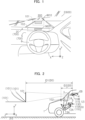
- Fig. 1 is a diagram illustrating a display mode of a first display image IM10 and a second display image IM20, which are visually recognized by an observer (typically, a driver of a vehicle) 4 when he/she faces the front from a driver's seat in a vehicle 1.
- an observer typically, a driver of a vehicle
- a left-right direction defined when the observer 4 who is seated in the driver's seat in the vehicle 1 faces the front of the vehicle 1 corresponds to the X-axis (the left direction is the X-axis positive direction)
- an up-down direction corresponds to the Y-axis (the up direction is the Y-axis positive direction)
- a front-rear direction corresponds to the Z-axis (the front direction is the Z-axis positive direction).
- a vehicular display system 10 of the present embodiment displays the first display image IM10 in a first display region 101 within a front scenery overlapping region 600, which is visually recognized to overlap front scenery 300 that is ahead of the vehicle 1, and displays the second display image IM20 in a second display region 102 within a front scenery non-overlapping region 700, which is visually recognized not to overlap the front scenery 300 that is ahead of the vehicle 1.
- a first display unit 110 displays the first display image IM10 in the first display region 101.
- the first display region 101 is provided in a region (an example of the front scenery overlapping region 600) overlapping a front windshield 2 of the vehicle 1 when viewed from the observer 4.
- the first display unit 110 of one embodiment of the vehicular display system 10 is a head-up display (HUD) device 110A provided within a dashboard 5 of the vehicle 1.
- the HUD device 110A emits display light 11A toward the front windshield 2 (i.e., an example of a projected member), and causes the first display image IM10 to be visually recognized in the first display region 101 on the front side (i.e., in the Z-axis positive direction) of the front windshield 2 (an example of the projected member).
- the observer 4 can visually recognize an image superimposed on the front scenery 300, which is a real space visually recognized through the front windshield 2.
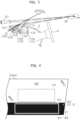
- Fig. 2 is a diagram illustrating an example of the arrangement of the first display region 101 and the second display region 102.
- the first display region 101 is an area of a flat surface, a curved surface, or a partially curved surface on which an image generated within the HUD device 110A is formed as a virtual image, and is also referred to as an image forming surface.
- the first display region 101 itself is not actually visually recognized by the observer 4, or visibility thereof is so low that it is hard to be visually recognized.
- the HUD device 110A includes a display 12A having a display surface which displays an image, and a relay optical system 13A.
- the display 12A may be a transmissive display that transmits light from a backlight, such as a liquid crystal display (LCD), or may be a projection display that projects an image onto a screen.
- the display surface is a display surface of the transmissive display or the screen of the projection display.
- the relay optical system 13A is disposed on an optical path of light of an image from the display 12A that is between the display 12A and the front windshield 2, and is configured from one or more optical members which project the light of the image from the display 12A onto the front windshield 2 on the outside of the first display unit 110. While the relay optical system 13A includes at least one concave mirror, the relay optical system 13A may include, for example, one or more refractive optical members such as a lens, diffractive optical members such as a hologram, and reflective optical members, or a combination thereof, in addition to the concave mirror.
- the first display unit 110 may be a head-mounted display (hereinafter referred to as an HMD) device 110B.
- an HMD head-mounted display
- the observer 4 wears the HMD device 110B on the head and sits on a seat of the vehicle 1, he/she visually recognizes a displayed image to be superimposed on the front scenery 300 through the front windshield 2 of the vehicle 1.
- the first display region 101 in which the vehicular display system 10 displays a predetermined image is fixed (or adjustably arranged) at a specific position with reference to the coordinate system of the vehicle 1, and as the observer 4 faces toward that direction, he/she can visually recognize the image displayed in the first display region 101 fixed at the specific position.
- the first display unit 110 displays an image in the vicinity of a real object (an example of a specific positional relationship between the image and the real object) in which the real object is, for example, an obstacle (a pedestrian, a bicycle, a motorcycle, other vehicles, or the like), a road surface 6 of a traffic lane, a road sign, and a ground object (a building, a bridge, or the like) being existent in the front scenery 300, which is the real space (an actual view) visually recognized through the front windshield 2 of the vehicle 1, or displays an image at a position overlapping the real object (an example of a specific positional relationship between the image and the real object) or at a position set with reference to the real object (an example of a specific positional relationship between the image and the real object).
- a real object an example of a specific positional relationship between the image and the real object
- the real object is, for example, an obstacle (a pedestrian, a bicycle, a motorcycle, other vehicles, or the like), a road surface 6 of a traffic lane
- the first display unit 110 can display images including an AR image whose display position is changed in accordance with the position of the real object and/or a non-AR image whose display position is not changed in accordance with the position of the real object.
- the first display region 101 is disposed at a position separated from a predetermined position in the vehicle 1 (for example, a predetermined position of an eyebox EB) by a first image distance ID1.
- the second display region 102 is disposed at a position separated by a second image distance ID2 shorter than the first image distance ID1. That is, the second display image IM20 displayed by the second display unit 120 is visually recognized by the observer 4 on the near side relative to the first display image IM10 that is displayed by the first display unit 110.
- the first image distance ID1 is, for example, 7 meters [m]
- the second image distance ID2 is, for example, 2 meters [m]. However, these values are merely examples and can be changed.
- the distance (image distance) ID1 from the predetermined position in the vehicle 1 to the first display region 101 may be 3 to 20 meters [m]. That is, the image distance ID1 to the near end (the lower end) of the first display region 101 may be 3 meters [m], and the image distance ID1 to the far end (the upper end) of the first display region 101 may be 20 meters [m].
- Fig. 3 is a diagram illustrating an example of the arrangement of the second display unit 120.
- the second display unit 120 of one embodiment of the vehicular display system 10 is a nearby HUD device 120A provided within the dashboard 5 of the vehicle 1.
- the nearby HUD device 120A emits the display light 11A toward a W/S light-shielding portion 2C (i.e., an example of a light-shielding portion 700) of the front windshield 2 (i.e., an example of a projected member), and causes the second display image IM20 to be visually recognized in the second display region 102 on the front side (i.e., in the Z-axis positive direction) of the front windshield 2 (an example of the projected member).
- the observer 4 can visually recognize an image that is not superimposed on the front scenery 300, which is the real space.
- the nearby HUD device 120A includes a display 22A having a display surface which displays an image.
- An optical path length of the display light 21A from the display 22A of the nearby HUD device 120A to a projected portion (the W/S light-shielding portion 2C) is set to be shorter than the optical path length of the display light 11A from the display 12A of the HUD device 110A to the projected portion (the W/S light-shielding portion 2C). That is, the second display image IM20 displayed by the nearby HUD device 120A is perceived by an observer 3 to be closer than the first display image IM10 that is displayed by the HUD device 110A. In other words, the second display region 102 is disposed closer to the driver's seat in the vehicle 1 than the first display region 101.
- the nearby HUD device 120A may also include a relay optical system (not illustrated).
- Fig. 4 is a diagram illustrating one embodiment of the arrangement of the first display region 101 and the second display region 102.
- the first display region 101 is the region (front scenery overlapping region) 600 in which the front scenery (actual view) 300 can be visually recognized by transmitting visible light at the front windshield 2, and is, for example, within a display region of the HUD device 110A (the first display unit 110).
- the second display region 102 is the region (front scenery non-overlapping region) 700 that does not overlap the front scenery (actual view) 300 beyond the front windshield 2, and is, for example, a region that overlaps the W/S light-shielding portion 2C (an example of the light-shielding portion 700) of the front windshield 2 or the dashboard 5 (an example of the light-shielding portion 700).
- the second display region 102 is, for the most part, within a region not overlapping the actual view beyond the front windshield 2.
- a part of the second display region 102 may be outside the region not overlapping the actual view beyond the front windshield 2 (in other words, within a region overlapping the actual view beyond the front windshield 2).
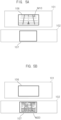
- Fig. 5A is a diagram illustrating the state in which the first display image IM10 is displayed in the first display region 101.
- the first display image IM10 is an overhead image of content as viewed obliquely downward, and is displayed at a predetermined first fixed position 106 in the first display region 101.
- Fig. 5B is a diagram illustrating the state in which the second display image IM20 is displayed in the second display region 102.
- the second display image IM20 is an image in which a depression angle is greater than that of the first display image IM10, and is displayed at a predetermined second fixed position 107 in the second display region 102.
- the vehicular display system 10 (the display control device 130) according to the present embodiment executes display position change processing of moving the content between the first display region 101 (the first fixed position 106) and the second display region 102 (the second fixed position 107).
- Fig. 6 is a block diagram of the vehicular display system 10 according to some embodiments.
- the display control device 130 includes one or more input/output (I/O) interfaces 131, one or more processors 133, one or more image processing circuits 135, and one or more memories 137.
- I/O input/output
- Various functional blocks illustrated in Fig. 6 may be configured by hardware, software, or a combination of both.
- Fig. 6 is merely one embodiment of the embodiments, and the constituent elements illustrated may be combined into fewer constituent elements, or additional constituent elements may be provided.
- the image processing circuit 135 e.g., a graphics processing unit
- the image processing circuit 135 may be included in the one or more processors 133.
- the processor 133 and the image processing circuit 135 are operably coupled to the memory 137. More specifically, as the processor 133 and the image processing circuit 135 execute a program stored in the memory 137, an operation of the vehicular display system 10, such as generating and/or transmitting image data, can be performed.
- the processor 133 and/or the image processing circuit 135 may include at least one general-purpose microprocessor (e.g., a central processing unit (CPU)), at least one application-specific integrated circuit (ASIC), at least one field programmable gate array (FPGA), or an arbitrary combination of the above.
- CPU central processing unit
- ASIC application-specific integrated circuit
- FPGA field programmable gate array
- the memory 137 includes an arbitrary type of magnetic medium such as a hard disk, an arbitrary type of optical medium such as a compact disc (CD) or a digital versatile disc (DVD), an arbitrary type of semiconductor memory such as a volatile memory, and a non-volatile memory.
- the volatile memory may include a dynamic random access memory (DRAM) and a static random access memory (SRAM), and the non-volatile memory may include a read-only memory (ROM) and a nonvolatile read-only memory (NVROM).
- the processor 133 is operably coupled to the I/O interface 131.
- the I/O interface 131 performs, in accordance with controller area network (CAN) standard, communication (also referred to as CAN communication) with, for example, a vehicle electronic control unit (ECU) to be described later provided in the vehicle, and other electronic devices (indicated by reference numerals 401 to 420 to be described later).
- CAN controller area network
- the communication standard adopted by the I/O interface 131 is not limited to CAN, and includes, for example, a wired communication interface such as a CAN with Flexible Data Rate (CANFD), a Local Interconnect Network (LIN), Ethernet (registered trademark), a Media Oriented Systems Transport (MOST) (MOST is a registered trademark), a Universal Asynchronous Receiver Transmitter (UART), or a Universal Serial Bus (USB), or an in-vehicle communication (interior communication) interface, which is an interface of short-range wireless communication within several tens of meters, including, for example, a personal area network (PAN) such as Bluetooth (registered trademark) network, and a local-area network (LAN) such as 802.11x Wi-Fi (registered trademark) network.
- PAN personal area network
- LAN local-area network
- 802.11x Wi-Fi registered trademark
- the I/O interface 131 may include a vehicle external communication (exterior communication) interface such as a wide-area communication network (e.g., Internet communication network) according to a cellular communication standard, such as wireless wide area network (WAN0, IEEE802.16-2004 (Worldwide Interoperability for Microwave Access (WiMAX)), IEEE802.16e Base (Mobile WiMAX), 4G, 4G-LTE, LTE Advanced, and 5G.
- WAN0 wireless wide area network
- IEEE802.16-2004 Worldwide Interoperability for Microwave Access (WiMAX)
- IEEE802.16e Base Mobile WiMAX
- 4G 4G-LTE
- LTE Advanced Long Term Evolution Advanced
- the processor 133 is coupled to the I/O interface 131 in a mutually operable manner, the processor 133 is enabled to exchange information with various other electronic devices and the like connected to the vehicular display system 10 (the I/O interface 131).
- a navigation device, the vehicle ECU, and a vehicle external communication device, etc., that are provided in the host vehicle 1 are operably coupled to the I/O interface 131.
- a first image generation unit 12 and a second image generation unit 22 are operably coupled to the processor 133 and the image processing circuit 135. Accordingly, the first display image IM1 displayed by the first display unit 110 and the second display image IM2 displayed by the second display unit 120 may be based on image date received from the processor 133 and/or the image processing circuit 135.
- the processor 133 and the image processing circuit 135 control the first display image IM10 displayed by the first display unit 110 and the second display image IM20 displayed by the second display unit 120 on the basis of information obtained from the I/O interface 131.
- the I/O interface 131 may include the function of processing (converting, computing, and analyzing) information received from other electronic devices or the like connected to the vehicular display system 10.
- a locator 410 illustrated in Fig. 6 is configured to mainly include a microcomputer provided with a processor, a RAM, a storage unit, an input/output interface, and a bus connecting these components, etc.
- the locator 410 combines positioning data received by a Global Navigation Satellite System (GNSS) device 411, a measurement result of an Inertial Measurement Unit (IMU) 412, and vehicle speed information and the like that has been output to the I/O interface 131, and sequentially measures the position of the vehicle of its own and a traveling direction or the like of the host vehicle 1.
- the locator 410 provides, to the display control device 130 and the like, positional information and direction information regarding the host vehicle 1 based on the position measurement result.
- GNSS Global Navigation Satellite System
- IMU Inertial Measurement Unit
- the GNSS device 411 illustrated in Fig. 6 receives a positioning signal transmitted from an artificial satellite (a positioning satellite), detects the current position of the host vehicle, and outputs the detected position data to the locator 410.
- the GNSS device 411 can receive a positioning signal from each of the positioning satellites of at least one satellite positioning system among the satellite positioning systems such as global positioning system (GPS), global navigation satellite system (GLONASS), Galileo, Indian Regional Navigational Satellite System (IRNSS), quasi-zenith satellite system (QZSS), and Beidou.
- GPS global positioning system
- GLONASS global navigation satellite system
- Galileo Galileo
- QZSS quasi-zenith satellite system
- Beidou Beidou
- the IMU 412 is an Inertial Measurement Unit and includes, for example, a gyroscope sensor and an acceleration sensor, and the IMU 412 detects angular velocities in each of yaw, pitch, and roll directions and outputs the detected angular velocity data to the locator 410. As the locator 410 detects the angular velocities in each of the yaw, pitch, and roll directions, a change in the posture of the vehicle is detected.
- a map information storage device 420 is a storage medium which stores map data including the periphery of the vehicle, and outputs, to the display control device 130, the map data of the periphery of the current position of the host vehicle on the basis of the positional information and the direction information regarding the host vehicle 1 that have been determined by the locator 410. Further, the map information storage device 420 outputs, to the display control device 130, a relative position (distance and direction) of a specific target (a feature point such as a building or a branching point on a road) on the basis of the positional information and the direction information regarding the host vehicle 1 that have been determined by the locator 410.
- a relative position distance and direction
- the map information storage device 420 is externally attached to the display control device 130.
- the map information storage device 420 may be incorporated in the display control device 130.
- the map information storage device 420 may be a server which distributes map information to the display control device 130 by means of communication from the outside of the host vehicle.
- the map information storage device 420 can acquire the latest map data from a server provided on the cloud.
- a navigation device 430 is a vehicle onboard unit which performs route guidance to a destination set by a driver, for example.
- the navigation device 430 is provided with a map database (not illustrated) for navigation.
- the map database for navigation is constituted by mainly using a non-volatile memory, and stores therein map data (hereinafter referred to as navigation map data) used for route guidance.
- the navigation map data indicates link data and node data, etc., regarding the roads.
- the navigation device 430 provides navigation information indicating the contents of the route guidance to the display control device 130.
- the navigation information includes, for example, positional information and road shape information regarding an intersection or a junction point, and directional information indicating the direction in which the vehicle should proceed at the intersection or the junction point.
- the periphery monitoring sensor 440 detects a specific target that exists at the periphery (the front, the side, and the rear) of the vehicle 1.
- the specific target detected by the periphery monitoring sensor 440 may include, for example, an obstacle (a pedestrian, a bicycle, a motorcycle, other vehicles, or the like), a road surface of a traffic lane which will be described later, a mark line, a roadside object, and/or a ground object (a building or the like).
- a vehicle external sensor is constituted of, for example, a detection unit configured from a radar sensor such as a millimeter-wave radar, an ultrasonic radar, or a laser radar, a camera, or an arbitrary combination of the above, and a processing device which processes detection data (i.e., fuses data) from one or more of the detection units.
- a radar sensor such as a millimeter-wave radar, an ultrasonic radar, or a laser radar, a camera, or an arbitrary combination of the above
- detection data i.e., fuses data
- the presence or absence of a specific target in a three-dimensional space may be detected, and if there exists a specific target, the position of the specific target (i.e., a relative distance from the vehicle 1, the position in the left-right direction when the traveling direction of the vehicle 1 is assumed as the front-rear direction, the position in the up-down direction, etc.) and the size (size in a transverse direction (left-right direction) and a height direction (up-down direction), etc.), a moving direction (the transverse direction (left-right direction) and a depth direction (front-rear direction)), a change rate (in the transverse direction (left-right direction) and the depth direction (front-rear direction)) of the specific target and/or the type of the specific target and the like may be detected.
- the position of the specific target i.e., a relative distance from the vehicle 1, the position in the left-right direction when the traveling direction of the vehicle 1 is assumed as the front-rear direction, the position in the up-down direction, etc.
- One or more of the periphery monitoring sensors 440 can detect a specific target ahead of the vehicle 1 for each detection cycle of the respective sensors, and output, to the processor 133, specific target information (the presence or absence of the specific target and if there exists a specific target, information such as the position, size, and/or type of the specific target for each specific target), which is an example of the specific target information.
- specific target information the presence or absence of the specific target and if there exists a specific target, information such as the position, size, and/or type of the specific target for each specific target
- These pieces of specific target information may be transmitted to the processor 133 via another device (e.g., the vehicle ECU).
- another device e.g., the vehicle ECU.
- an infrared camera or a near-infrared camera should preferably be used so that the specific target may be detected even when the surroundings are dark, such as at night.
- a stereo camera capable of acquiring a distance and the like by a parallax is preferred.
- a viewer detection device 450 may include a camera such as an infrared camera which detects the eye position of the observer who is seated in the driver's seat in the vehicle 1 and may output a captured image to the processor 133.
- the processor 133 may acquire a captured image (an example of information from which the eye position can be estimated) from the viewer detection device 450, and analyze the captured image by a method such as pattern matching, thereby detecting the coordinates of the eye position of the observer, and outputting a signal indicating the detected coordinates of the eye position to the processor 133.
- the viewer detection device 450 may output, to the processor 133, an analysis result obtained by analyzing the captured image of the camera (e.g., a signal indicating where the eye position of the observer belongs to in a spatial area to which a plurality of preset display parameters correspond).
- an analysis result obtained by analyzing the captured image of the camera e.g., a signal indicating where the eye position of the observer belongs to in a spatial area to which a plurality of preset display parameters correspond.
- the method of acquiring the eye position of the observer of the vehicle 1 or the information from which the eye position of the observer can be estimated is not limited to these methods.
- the eye position or the information may be acquired by using a known eye position detection (estimation) technique.
- the viewer detection device 450 may detect a change rate and/or a moving direction of the eye position of the observer and output, to the processor 133, a signal indicating the change rate and/or the moving direction of the eye position of the observer.
- a vehicle external communication connection device 460 is a communication device which exchanges information with the host vehicle 1, and is, for example, other vehicles connected to the host vehicle 1 by vehicle-to-vehicle (V2V) communication, pedestrians (portable information terminals carried by pedestrians) connected by vehicle-to-pedestrian (V2P) communication, and network communication devices connected by vehicle-to-roadside Infrastructure (V2I) communication.
- V2V vehicle-to-vehicle
- V2P vehicle-to-pedestrian
- V2I vehicle-to-roadside Infrastructure
- the vehicle external communication connection device 460 includes everything connected by vehicle-to-everything (V2X) communication with the host vehicle 1.
- the vehicle external communication connection device 460 may acquire, for example, the position of a pedestrian, a bicycle, a motorcycle, other vehicles (a preceding vehicle, etc.), a road surface, a mark line, a roadside object, and/or a ground object (a building, etc.) and transmit the acquired position to the processor 133. Furthermore, the vehicle external communication connection device 460 may have the same function as that of the locator 410 described above, and transmit the positional information and the direction information regarding the host vehicle 1 to the display control device 130 and the like. Further, the vehicle external communication connection device 460 may have the function of the above-described road information database 403, and acquire the road information (an example of peripheral vehicle-related information) and transmit the acquired information to the processor 133. Note that the information acquired from the vehicle external communication connection device 460 is not limited to the above-described information.
- Software constituent elements stored in the memory 137 include a navigation image generation module 512 (an example of an overhead image generation module 510), a periphery monitoring image generation module 514 (an example of the overhead image generation module 510), a determination module 520, and an image switching module 530.
- the navigation image generation module 512 executes, for example, setting the position of a virtual viewpoint MM with respect to a host vehicle position icon PP on a map, which will be described later, and a look-down angle (a depression angle) ⁇ from the virtual viewpoint MM; changing the scale of a course guidance image 200; setting a virtual visual field E which determines the shape of a map around the host vehicle position icon PP to be cut out; and reading map data around the host vehicle from a map database 401, and generating, as the course guidance image, an image observed at a predetermined depression angle and in a predetermined virtual visual field from a predetermined position of the virtual viewpoint MM.
- the navigation image generation module 512 disposes, on the basis of the map data and the navigation information, a virtual object for route guidance on a virtual road model at the periphery of the host vehicle 1, and sets a virtual viewpoint position over the host vehicle 1 on the basis of locator information (the position and the angle of the host vehicle 1). Then, the navigation image generation module 512 displays the virtual object viewed from the virtual viewpoint position as an overhead navigation image IM31 (an example of an overhead image IM30) to be described later.
- the navigation image generation module 512 may be omitted, and the display control device 130 may acquire image data of the overhead navigation image IM31 (an example of the overhead image IM30) from the navigation device 430 or the like via the I/O interface 131.
- Fig. 7 is a diagram illustrating a region of a map image of the surroundings of the host vehicle displayed as the overhead navigation image IM31.
- the map is an ⁇ plane
- the virtual viewpoint position MM for displaying a bird's eye view is at a position of a height M ⁇ on a ⁇ -axis orthogonal to the ⁇ plane, more specifically, behind and over the host vehicle position icon PP.
- the virtual viewpoint position MM is set at a position separated by M ⁇ 1 in the rear of the host vehicle position icon PP (i.e., in the ⁇ negative direction) and by M ⁇ 1 in the above (i.e., in the ⁇ positive direction).
- M ⁇ 1 in the rear of the host vehicle position icon PP i.e., in the ⁇ negative direction
- M ⁇ 1 in the above i.e., in the ⁇ positive direction
- the range of the map surrounded by a rectangular virtual visual field F1G1H1J1 at the look-down angle ⁇ from the virtual viewpoint position MM can be represented as a trapezoid surrounded by reference numerals F2G2H2J2 having a wider range in the left-right direction ( ⁇ direction) on the far side (i.e., in the ⁇ positive direction) and a narrower range in the left-right direction ( ⁇ direction) on the near side (in the ⁇ negative direction).
- the virtual visual field E may have a narrower width in the left-right direction ( ⁇ direction) in an area overlapping the far area of the map than the rectangular virtual visual field FGHJ.
- the area of the map surrounded by the virtual visual field E (F1K1L1J1) observed from the virtual viewpoint position MM is surrounded by reference numerals F2K2L2J2, and the range of this area in the left-right direction ( ⁇ direction) is narrower on the far side (i.e., in the ⁇ positive direction) than the range surrounded by the reference numerals F2G2H2J2.
- the navigation image generation module 512 sets the virtual viewpoint position MM at a position separated by M ⁇ in the rear of the host vehicle position icon PP (i.e., in the ⁇ negative direction) and by M ⁇ in the above (i.e., in the ⁇ positive direction). Therefore, when the host vehicle is traveling straight on a straight traveling road, if the host vehicle position icon PP is viewed from the virtual viewpoint position MM, the overhead navigation image IM31 indicating traveling with the host vehicle position icon PP facing the front is generated. As the virtual viewpoint position MM moves, the map image of the periphery of the host vehicle is rotated (i.e., the angle is changed) and displayed.
- the virtual viewpoint position MM is also rotated by 90 degrees counterclockwise in conjunction with the rotation of the host vehicle position icon PP.
- the navigation image generation module 512 reduces the distance between the host vehicle position icon PP and the virtual viewpoint position MM. Specifically, at least one of the distance M ⁇ in the front-rear direction ( ⁇ direction) and the height M ⁇ in the up-down direction ( ⁇ direction) is reduced so that the distance between the host vehicle position icon PP and the virtual viewpoint position MM is reduced.
- the navigation image generation module 512 may increase the scale of the overhead navigation image IM31 (may increase the same in a stepwise manner) as the route change point (e.g., a branch road) becomes closer.
- the navigation image generation module 512 sets the position M ⁇ (M ⁇ ) and the angle ⁇ of the virtual viewpoint position MM with respect to the map image. As the navigation image generation module 512 changes the position M ⁇ (M ⁇ ) and the angle ⁇ of the virtual viewpoint, the navigation image generation module 512 changes the angle (depression angle) with respect to the map image of the surroundings of the host vehicle, which is to be displayed as the overhead navigation image IM31. Typically, the navigation image generation module 512 causes the position of the "virtual viewpoint" to be set at the periphery of the host vehicle (usually at an appropriate place behind the host vehicle).
- the angle ⁇ of the "virtual viewpoint” is an angle between the ⁇ plane and a direction passing through the midpoint in a vertical direction of the virtual visual field E1, which will be described later, from the virtual viewpoint position MM, and is hereinafter also referred to as the depression angle.
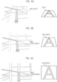
- Fig. 8 is a diagram illustrating the virtual viewpoints MM having different depression angles ⁇ with respect to a predetermined virtual object (content) 800.
- a virtual viewpoint MM1 has a depression angle ⁇ 1, and the depression angle ⁇ 1 is, for example, 20 degrees.
- a virtual viewpoint MM2 has a depression angle ⁇ 2 (> ⁇ 1), and the depression angle ⁇ 2 is, for example, 60 degrees.
- a virtual viewpoint MM3 has a depression angle ⁇ 3 (> ⁇ 2), and the depression angle ⁇ 3 is, for example, 90 degrees.
- the virtual object (content) 800 is a navigation image IM30 or a periphery monitoring image (not illustrated). In order to facilitate understanding of the difference in the depression angle ⁇ , the virtual object (content) 800 is denoted as "A" in Fig. 8 and the like.
- Fig. 9A is a diagram illustrating the virtual object (content) 800 as seen from the virtual viewpoint MM1 (depression angle ⁇ 1) of Fig. 8 (the right figure), and the navigation image IM31 (the left figure).
- Fig. 9B is a diagram illustrating the virtual object (content) 800 as seen from the virtual viewpoint MM2 (depression angle ⁇ 2) of Fig. 8 (the right figure), and a navigation image IM32 (the left figure).
- Fig. 9C is a diagram illustrating the virtual object (content) 800 as seen from the virtual viewpoint MM3 (depression angle ⁇ 3) of Fig. 8 (the right figure), and a navigation image IM33 (the left figure). If the navigation image IM31 of Fig.
- the second display image IM20 may include a second display image IM21 in which the depression angle ⁇ is greater than that of the first display image IM10 and smaller than 90 degrees, and a second display image IM22 in which the depression angle ⁇ is 90 degrees that is greater than a depression angle ⁇ of the first display image IM10.
- FIG. 9B are images in which the depression angle ⁇ is an acute angle and which represent the content as viewed obliquely downward, and can be assumed as a 3D representation.
- the second display image IM22 (IM20) indicated in Fig. 9C is an image in which the depression angle ⁇ is 90 degrees and the virtual viewpoint MM is disposed to be directly opposed to the content, and can be assumed as a 2D representation.
- the display control device 130 executes at least one of gradually increasing the depression angle ⁇ when moving the content 800 from the first display unit 110 (the first display region 101) to the second display unit 120 (the second display region 102) and gradually decreasing the depression angle ⁇ when moving the content from the second display unit 120 (the second display region 102) to the first display unit 110 (the first display region 101).
- the display control device 130 while gradually increasing the depression angle ⁇ , the content 800 which has been displayed on the first display unit 110 is moved toward the predetermined second fixed position 107 in the second display unit 120 where the image distance ID0 is short.
- the display control device 130 while gradually decreasing the depression angle ⁇ , the content 800 which has been displayed on the second display unit 120 is moved toward the predetermined first fixed position 106 in the first display unit 110 where the image distance ID0 is long. Consequently, it is possible to assume an advantage of being able to give the impression that the content 800 has moved away to the far side in an emphasized way.
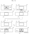
- Fig. 10 is a diagram illustrating one embodiment of transition of a display image in the display position change processing executed by the display control device 130.
- the display control device 130 moves the virtual object (content) 800 from the first display region 101 (the first fixed position 106) to the second display region 102 (the second fixed position 107) while gradually increasing the depression angle ⁇ .
- the display control device 130 moves the virtual object (content) 800 from the second display region 102 (the second fixed position 107) to the first display region 101 (the first fixed position 106) while gradually decreasing the depression angle ⁇ .
- the display control device 130 moves the virtual object (content) 800 from the second display region 102 (the second fixed position 107) to the first display region 101 (the first fixed position 106) while gradually decreasing the depression angle ⁇ .
- the virtual object 800 is displayed as the first display image IM10 at the first fixed position 106.
- the display control device 130 moves the first display image IM10 which has been displayed at the first fixed position 106 toward the second display region 102 (the second fixed position 107).
- a first transition image IM15 (in which a solid line portion is displayed and a dotted line portion is not displayed) in (b) of Fig. 10 is moving inside the first display region 101 from the first fixed position 106 toward the second fixed position 107, and the depression angle ⁇ is set to be greater than that of the first display image IM10 in (a) of Fig. 10 .
- a second transition image IM25 (in which a solid line portion is displayed and a dotted line portion is not displayed) in (c) of Fig. 10 is moving inside the second display region 102 from the first fixed position 106 toward the second fixed position 107, and the depression angle ⁇ is set to be greater than that of the first transition image IM15 in (b) of Fig. 10 .
- the second display image IM20 in (d) of Fig. 10 the movement from the first fixed position 106 toward the second fixed position 107 is completed, and the second display image IM20 is positioned at the second fixed position 107 and the depression angle ⁇ is set to be greater than that of the first transition image IM15 in (b) of Fig. 10 .
- the processor 133 gradually changes, at the movement source, the depression angle ⁇ in the display position change processing.
- the observer 4 can predict that the display position of the content 800 will be changed, and also the next display position (a movement destination) of the content 800 from the change in the depression angle ⁇ .
- a change of the depression angle ⁇ is started early within the display region of the movement source.
- the processor 133 in the display position change processing, gradually changes, at the movement source, the depression angle ⁇ while moving the content 800 to the movement destination side.
- the content 800 which has been displayed on the first display unit 110, moves toward the second display unit 120 where the image distance ID0 is short with the depression angle ⁇ being gradually increased, and is finally displayed at the predetermined second fixed position 107 in the second display unit 120 where the image distance ID0 is short. Therefore, it is possible to assume an advantage of being able to give the impression that the content 800 has come close to the near side in an emphasized way even when the content 800 is in the process of making a move on the first display unit 110.
- the content 800 which has been displayed on the second display unit 120, moves toward the first display unit 110 where the image distance ID0 is long with the depression angle ⁇ being gradually decreased, and is finally displayed at the predetermined first fixed position 106 in the first display unit 110 where the image distance ID0 is long. Therefore, it is possible to assume an advantage of being able to give the impression that the content 800 is moving away to the far side in an emphasized way even when the content 800 is in the process of making a move on the second display unit 120.
- the display is not limited to the above, and in the display position change processing, the processor 133 according to some embodiments may gradually change the depression angle ⁇ of the content 800 at the movement source, and thereafter, stop the display of the content 800 at the movement source (for example, perform slide out, fade out, or a combination thereof).
- the processor 133 at the movement destination, while the processor 133 allows the content 800 to be moved from the movement source side, the processor 133 does not change the depression angle ⁇ in the display position change processing.
- the processor 133 by virtue of the change in the depression angle ⁇ and the movement of the display position of the content 800 at the movement source, it is possible to give the impression that the image distance ID0 of the content 800 is changing in an emphasized way, and it is also possible to make an impression of there being a change in the depression angle ⁇ of the content 800 in an emphasized way. For this reason, a change of the depression angle of the content at the movement destination is not necessarily required.
- the present display control device it is possible to assume an advantage of being able to reduce a change of the depression angle ⁇ at the movement destination, which may be a redundant expression at the movement source, and reduce a control load.
- the display is not limited to the above, and in the processor 133 according to some embodiments, the processor 133 may, in the display position change processing, move the content 800 from the movement source side and also change the depression angle ⁇ at the movement destination.
- the processor 133 reduces the content at the movement source. Further, if the size of the content 800 at the movement destination is larger than the size of the content 800 at the movement source, the processor 133 enlarges the content 800 at the movement source. In a case where the size of the content 800 differs greatly between the movement source and the movement destination, a large difference is caused in the size of the content 800 to be visually recognized when the display unit on which the content 800 is displayed is switched. Thus, it is presumed that the switched content is hard to be recognized as being the same content.
- the size of the content 800 is enlarged or reduced at the movement source such that the size becomes close to that of the content at the movement destination.
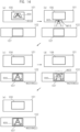
- Fig. 11 is a diagram illustrating one embodiment of transition of a display image in the display position change processing executed by the display control device 130.
- the display control device 130 moves the virtual object (content) 800 from the first display region 101 (the first fixed position 106) to the second display region 102 (the second fixed position 107) while enlarging the virtual object (content) 800.
- the display control device 130 moves the virtual object (content) 800 from the second display region 102 (the second fixed position 107) to the first display region 101 (the first fixed position 106) while reducing the virtual object (content) 800.
- the virtual object 800 is displayed as the first display image IM10 at the first fixed position 106.
- the display control device 130 moves the first display image IM10 which has been displayed at the first fixed position 106 toward the second display region 102 (the second fixed position 107).
- the first transition image IM15 in which a solid line portion is displayed and a dotted line portion is not displayed) in (b) of Fig. 11 is moving inside the first display region 101 from the first fixed position 106 toward the second fixed position 107, and is set such that the depression angle ⁇ and also the size are greater than those of the first display image IM10 in (a) of Fig. 11 .
- the second transition image IM25 (in which a solid line portion is displayed and a dotted line portion is not displayed) in (c) of Fig. 11 is moving inside the second display region 102 from the first fixed position 106 toward the second fixed position 107, and is set such that the depression angle ⁇ and also the size are greater than those of the first transition image IM15 in (b) of Fig. 11 .
- the second display image IM20 in (d) of Fig. 11 the movement from the first fixed position 106 toward the second fixed position 107 is completed, and the second display image IM20 is positioned at the second fixed position 107 and the depression angle ⁇ is set to be greater than that of the first transition image IM15 in (b) of Fig. 11 (the size is substantially the same).
- the processor 133 changes, at the movement source, the content 800 in a form which becomes gradually invisible from an end portion of the content 800 on the movement destination side.
- the display control device by changing the content in a form which becomes gradually invisible from the end portion of the content on the movement destination side in a state in which the content is stopped (is not moving), it is also possible to assume an advantage of being able to cause the observer to perceive that the content has moved to the movement destination even without moving the content.
- the display control device with the content moving toward the movement destination, by changing the content in a form which becomes gradually invisible from the end portion of the content on the movement destination side, it is also possible to assume an advantage of being able to cause the observer to perceive that the content is moving in an emphasized way.
- Fig. 12 is a diagram for describing display transition of the content.
- the first transition image IM15 is gradually changed to be in a state of being invisible (i.e., the state in which a dotted line portion is invisible) from an end portion (a lower end) of the first transition image IM15 that is close to the movement destination (the second display region 102) to an end portion (an upper end) of the same on the opposite side.
- the content 800 is made to fade out from the end portion on the movement destination side.
- the content included in the first display image IM10 is a part of the content included in the second display image IM20.
- the display control device 130 according to the present embodiment increases or decreases the amount of information of the content 800. By doing so, it is possible to adjust the amount of information and attractiveness of an image, and it is assumed that the convenience is enhanced.
- Fig. 13 is a diagram illustrating a display mode of the first display image IM10 (upper diagram) and the second display image IM20 (lower diagram).
- the display control device 130 may perform display control such that the first display image IM10 includes a part of the content items ("B, C, F, G") that are included in the second display image IM20 but does not include a part of the same ("A, D, E, H").
- the first display image IM10 has a predetermined first depth representation
- the second display image IM20 does not have the first depth representation.
- the display control device 130 according to the present embodiment switches a method of representation between the first display image IM10 having the first depth representation and the second display image IM20 not having the first depth representation, whereby a change in the depression angle ⁇ with respect to the content 800 is further emphasized. It is possible to make an impression of there being a difference between the distances (image distances) ID0, which are displayed by such an emphasis on the change in the depression angle ⁇ , in an emphasized way.
- the first depth representation is a representation which reduces the sharpness of the content on the back side.
- Examples of the mode of the first depth representation include the following: (1) In the first depth representation, the back side is displayed light and the near side is displayed dark. (2) In the first depth representation, a contour line or shade is made thin on the back side, and the same is made thick on the near side. (3) In the first depth representation, the closer to the back side, the lower the saturation is made, and the closer to the near side, the higher the saturation is made (however, depending on the hue of the background or the like, the opposite case is also possible). (4) In the first depth representation, the brightness (luminance) on the back side is made low, and the same on the near side is made high (however, depending on the luminance or the brightness of the background, the opposite case is also possible). (5) In the first depth representation, the contrast ratio to the background is made low on the back side, and the same on the near side is made high (however, depending on the color or the color tone, etc., of the background, the opposite case is also possible).
- the display control device 130 determines whether a first condition for switching the display position (moving the display position) of the content 800 from the first display unit 110 (the first display region 101) to the second display unit 120 (the second display region 102) is satisfied or a second condition for switching the display position (moving the display position) of the content 800 from the second display unit 120 (the second display region 102) to the first display unit 110 (the first display region 101) is satisfied.
- the first condition examples include the following: (1) The first display image IM10 is a menu content selected by an operation of the observer 4, and a specific operation is detected by the observer 4 on the menu content. (2) A decrease in a degree of priority of displaying the first display image IM10 is detected. (3) A situation in which a line of sight of the observer 4 is desired to be guided to the second display region 102 is detected. (4) It is determined that the information of the first display image IM10 is unsuitable for the front scenery 300. (5) Other information to be displayed in the first display region 101 is detected. (6) A condition for ending the display by the first display unit 110 is satisfied. Note that the first condition is not limited to the above.
- Examples of the second condition include the following: (1) An increase in a degree of priority of displaying the content 800 is detected. (2) A situation in which a line of sight of the observer 4 is desired to be guided to the first display region 101 is detected. (3) It is determined that a situation in which the content 800 should be displayed together with the front scenery 300 has occurred. (4) It is determined that a situation in which the observer 4 should be alerted has occurred. Note that the second condition is not limited to the above.
- Fig. 14 is a diagram illustrating one embodiment of transition of a display image in the display position change processing executed by the display control device 130.
- the display control device 130 moves the virtual object (content) 800 from the first display region 101 (the first fixed position 106) to the second display region 102 (the second fixed position 107).
- the display control device 130 moves the virtual object (content) 800 from the second display region 102 (the second fixed position 107) to the first display region 101 (the first fixed position 106).
- the display control device 130 moves the virtual object (content) 800 from the second display region 102 (the second fixed position 107) to the first display region 101 (the first fixed position 106).
- the virtual object 800 is displayed as the first display image IM10 at the first fixed position 106.
- the display control device 130 moves the first display image IM10 which has been displayed at the first fixed position 106 toward the second display region 102 (the second fixed position 107).
- the first transition image IM15 (in which a solid line portion is displayed and a dotted line portion is not displayed) in (b) of Fig. 14 is moving inside the first display region 101 from the first fixed position 106 toward the second fixed position 107, and the depression angle ⁇ is set to be greater than that of the first display image IM10 in (a) of Fig. 14 .
- the depression angle ⁇ is set to be greater than that of the first display image IM10 in (a) of Fig. 14 .
- the second display image IM20 is displayed in the second display region 102 (the second fixed position 107).
- the second transition image IM25 (in which a solid line portion is displayed and a dotted line portion is not displayed) in (d) of Fig. 14 is moving inside the second display region 102 from the first fixed position 106 toward the second fixed position 107, and the depression angle ⁇ is set to be greater than that of the first transition image IM15 in (b) of Fig. 14 .
- the second transition image IM25 in (d) of Fig. 14 is gradually made close to the second display image IM20, and then fades out.
- the second display image IM20 in (e) of Fig. 14 is the image displayed in (c) of Fig. 14 being displayed as it is when the second transition image IM25 in (d) of Fig. 14 has faded out.
- the second display unit 120 may be a display panel provided between the dashboard 5 and the front windshield 2.
- a second display unit 120B of Fig. 15 is a display panel which is provided on the dashboard 5 closer to the driver 4 than a light transmission portion 26 of a head-up display device 120A and whose back surface is held by a light-shielding portion 125.
- the second display region 102 where the second display unit 120D of Fig. 15 displays the second display image IM20 is disposed in the region (front scenery non-overlapping region) 700 that does not overlap the actual view beyond the front windshield 2.
- the second display unit 120 is a display panel which is provided on the dashboard 5 further to the back side (i.e., at a position distant from the driver 4) than the light transmission portion 26 of a head-up display device 20A and whose back surface is held by the light-shielding portion 125.
- the second display region 102 where a second display unit 120C of Fig. 16 displays the second display image IM20 is disposed in the region (front scenery non-overlapping region) 700 that does not overlap the actual view beyond the front windshield 2.
- the functional blocks of the vehicular display system 10 are executed arbitrarily and selectively by hardware, software, or a combination of the hardware and the software to put into practice the principles of the various embodiments described. It will be understood by those skilled in the art that the functional blocks described in Fig. 2 may be arbitrarily and selectively combined or that one functional block may be separated as two or more sub-blocks to implement the principles of the embodiments described. Therefore, the descriptions of the present specification arbitrarily and selectively support any possible combination or division of the functional blocks described herein.
Landscapes
- Engineering & Computer Science (AREA)
- Chemical & Material Sciences (AREA)
- Combustion & Propulsion (AREA)
- Transportation (AREA)
- Mechanical Engineering (AREA)
- Physics & Mathematics (AREA)
- General Physics & Mathematics (AREA)
- Theoretical Computer Science (AREA)
- Computer Hardware Design (AREA)
- Human Computer Interaction (AREA)
- General Engineering & Computer Science (AREA)
- Optics & Photonics (AREA)
- Instrument Panels (AREA)
- Fittings On The Vehicle Exterior For Carrying Loads, And Devices For Holding Or Mounting Articles (AREA)
Applications Claiming Priority (2)
| Application Number | Priority Date | Filing Date | Title |
|---|---|---|---|
| JP2022073589 | 2022-04-27 | ||
| PCT/JP2023/016429 WO2023210682A1 (ja) | 2022-04-27 | 2023-04-26 | 表示制御装置、ヘッドアップディスプレイ装置、及び表示制御方法 |
Publications (2)
| Publication Number | Publication Date |
|---|---|
| EP4516556A1 true EP4516556A1 (de) | 2025-03-05 |
| EP4516556A4 EP4516556A4 (de) | 2026-04-22 |
Family
ID=88519089
Family Applications (1)
| Application Number | Title | Priority Date | Filing Date |
|---|---|---|---|
| EP23796422.6A Pending EP4516556A4 (de) | 2022-04-27 | 2023-04-26 | Anzeigesteuerungsvorrichtung, head-up-anzeigevorrichtung und anzeigesteuerungsverfahren |
Country Status (5)
| Country | Link |
|---|---|
| US (1) | US20250069530A1 (de) |
| EP (1) | EP4516556A4 (de) |
| JP (1) | JPWO2023210682A1 (de) |
| CN (1) | CN119053470A (de) |
| WO (1) | WO2023210682A1 (de) |
Families Citing this family (2)
| Publication number | Priority date | Publication date | Assignee | Title |
|---|---|---|---|---|
| CN115145671B (zh) * | 2022-06-30 | 2026-02-10 | 腾讯科技(深圳)有限公司 | 车辆导航方法、装置、设备、存储介质和计算机程序产品 |
| CN120742556A (zh) * | 2025-09-08 | 2025-10-03 | 江苏泽景汽车电子股份有限公司 | 一种抬头显示系统 |
Family Cites Families (12)
| Publication number | Priority date | Publication date | Assignee | Title |
|---|---|---|---|---|
| US10215583B2 (en) * | 2013-03-15 | 2019-02-26 | Honda Motor Co., Ltd. | Multi-level navigation monitoring and control |
| JP6176478B2 (ja) * | 2013-04-26 | 2017-08-09 | 日本精機株式会社 | 車両情報投影システム |
| WO2015037325A1 (ja) * | 2013-09-12 | 2015-03-19 | 株式会社デンソー | 車載表示装置 |
| JP6123761B2 (ja) * | 2014-09-05 | 2017-05-10 | トヨタ自動車株式会社 | 車両用表示装置 |
| JP6661883B2 (ja) * | 2015-02-09 | 2020-03-11 | 株式会社デンソー | 車両用表示制御装置及び車両用表示制御方法 |
| JP6703747B2 (ja) * | 2015-09-18 | 2020-06-03 | 株式会社リコー | 情報表示装置、情報提供システム、移動体装置、情報表示方法及びプログラム |
| WO2017163292A1 (ja) * | 2016-03-24 | 2017-09-28 | パナソニックIpマネジメント株式会社 | ヘッドアップディスプレイ装置、及び車両 |
| JP2018066837A (ja) * | 2016-10-19 | 2018-04-26 | 三菱電機株式会社 | 虚像表示装置 |
| JP6361794B2 (ja) * | 2017-07-07 | 2018-07-25 | 日本精機株式会社 | 車両情報投影システム |
| CN108459415A (zh) * | 2018-03-28 | 2018-08-28 | 京东方科技集团股份有限公司 | 一种平视显示器、平视显示方法以及车辆 |
| JP6978988B2 (ja) * | 2018-08-07 | 2021-12-08 | 本田技研工業株式会社 | 表示装置、表示制御方法、およびプログラム |
| JP7172730B2 (ja) * | 2019-02-27 | 2022-11-16 | 株式会社デンソー | 車両用表示制御装置、車両用表示制御方法、車両用表示制御プログラム |
-
2023
- 2023-04-26 US US18/847,904 patent/US20250069530A1/en active Pending
- 2023-04-26 CN CN202380034481.5A patent/CN119053470A/zh active Pending
- 2023-04-26 EP EP23796422.6A patent/EP4516556A4/de active Pending
- 2023-04-26 WO PCT/JP2023/016429 patent/WO2023210682A1/ja not_active Ceased
- 2023-04-26 JP JP2024517991A patent/JPWO2023210682A1/ja active Pending
Also Published As
| Publication number | Publication date |
|---|---|
| US20250069530A1 (en) | 2025-02-27 |
| JPWO2023210682A1 (de) | 2023-11-02 |
| CN119053470A (zh) | 2024-11-29 |
| WO2023210682A1 (ja) | 2023-11-02 |
| EP4516556A4 (de) | 2026-04-22 |
Similar Documents
| Publication | Publication Date | Title |
|---|---|---|
| US11996018B2 (en) | Display control device and display control program product | |
| CN113165510B (zh) | 显示控制装置、方法和计算机程序 | |
| US12485755B2 (en) | Display control device, display system, and display control method | |
| JP7416114B2 (ja) | 表示制御装置および表示制御プログラム | |
| EP4516556A1 (de) | Anzeigesteuerungsvorrichtung, head-up-anzeigevorrichtung und anzeigesteuerungsverfahren | |
| WO2021049215A1 (ja) | 表示制御装置、および表示制御プログラム | |
| JP2020032866A (ja) | 車両用仮想現実提供装置、方法、及びコンピュータ・プログラム | |
| US10922976B2 (en) | Display control device configured to control projection device, display control method for controlling projection device, and vehicle | |
| JP2020196416A (ja) | 表示制御装置および表示制御プログラム | |
| US12162354B2 (en) | Display control device, head-up display device, and display control method | |
| JP7459883B2 (ja) | 表示制御装置、ヘッドアップディスプレイ装置、及び方法 | |
| JP7619007B2 (ja) | 表示制御装置、ヘッドアップディスプレイ装置、及び表示制御方法 | |
| JP2020199883A (ja) | 表示制御装置、ヘッドアップディスプレイ装置、方法、及びコンピュータ・プログラム | |
| JP2021133874A (ja) | 表示制御装置、ヘッドアップディスプレイ装置、及び方法 | |
| US12571652B2 (en) | Display control device, head-up display device, and display control method | |
| JP2020117105A (ja) | 表示制御装置、方法、及びコンピュータ・プログラム | |
| JP2020154468A (ja) | 運転支援装置、方法、及びコンピュータ・プログラム | |
| JP7014206B2 (ja) | 表示制御装置および表示制御プログラム | |
| WO2021200914A1 (ja) | 表示制御装置、ヘッドアップディスプレイ装置、及び方法 | |
| JP2021160409A (ja) | 表示制御装置、画像表示装置、及び方法 | |
| JP7635559B2 (ja) | 表示制御装置、ヘッドアップディスプレイ装置、及び表示制御方法 | |
| JP2020121607A (ja) | 表示制御装置、方法、及びコンピュータ・プログラム | |
| CN118613382A (zh) | 显示控制装置、显示系统及显示控制方法 | |
| JP2024119397A (ja) | 表示制御装置、方法、表示装置 | |
| JP2020187068A (ja) | 表示制御装置、ヘッドアップディスプレイ装置、方法、及びコンピュータ・プログラム |
Legal Events
| Date | Code | Title | Description |
|---|---|---|---|
| STAA | Information on the status of an ep patent application or granted ep patent |
Free format text: STATUS: THE INTERNATIONAL PUBLICATION HAS BEEN MADE |
|
| PUAI | Public reference made under article 153(3) epc to a published international application that has entered the european phase |
Free format text: ORIGINAL CODE: 0009012 |
|
| STAA | Information on the status of an ep patent application or granted ep patent |
Free format text: STATUS: REQUEST FOR EXAMINATION WAS MADE |
|
| 17P | Request for examination filed |
Effective date: 20241025 |
|
| AK | Designated contracting states |
Kind code of ref document: A1 Designated state(s): AL AT BE BG CH CY CZ DE DK EE ES FI FR GB GR HR HU IE IS IT LI LT LU LV MC ME MK MT NL NO PL PT RO RS SE SI SK SM TR |
|
| DAV | Request for validation of the european patent (deleted) | ||
| DAX | Request for extension of the european patent (deleted) | ||
| REG | Reference to a national code |
Ref country code: DE Ref legal event code: R079 Free format text: PREVIOUS MAIN CLASS: B60K0035000000 Ipc: B60K0035210000 |
|
| A4 | Supplementary search report drawn up and despatched |
Effective date: 20260325 |
|
| RIC1 | Information provided on ipc code assigned before grant |
Ipc: B60K 35/21 20240101AFI20260319BHEP Ipc: B60K 35/22 20240101ALI20260319BHEP Ipc: B60K 35/233 20240101ALI20260319BHEP Ipc: B60K 35/235 20240101ALI20260319BHEP Ipc: B60K 35/28 20240101ALI20260319BHEP Ipc: B60K 35/29 20240101ALI20260319BHEP Ipc: B60K 35/60 20240101ALI20260319BHEP Ipc: B60K 35/81 20240101ALI20260319BHEP Ipc: G02B 27/01 20060101ALI20260319BHEP Ipc: G06F 3/14 20060101ALI20260319BHEP Ipc: G09G 3/00 20060101ALI20260319BHEP Ipc: G09G 5/00 20060101ALI20260319BHEP |