EP4513623A2 - Energiespeicherschrank und batteriepack dafür - Google Patents
Energiespeicherschrank und batteriepack dafür Download PDFInfo
- Publication number
- EP4513623A2 EP4513623A2 EP24196071.5A EP24196071A EP4513623A2 EP 4513623 A2 EP4513623 A2 EP 4513623A2 EP 24196071 A EP24196071 A EP 24196071A EP 4513623 A2 EP4513623 A2 EP 4513623A2
- Authority
- EP
- European Patent Office
- Prior art keywords
- housing
- battery pack
- side opening
- liquid
- cooling liquid
- Prior art date
- Legal status (The legal status is an assumption and is not a legal conclusion. Google has not performed a legal analysis and makes no representation as to the accuracy of the status listed.)
- Pending
Links
Images


Classifications
-
- H—ELECTRICITY
- H01—ELECTRIC ELEMENTS
- H01M—PROCESSES OR MEANS, e.g. BATTERIES, FOR THE DIRECT CONVERSION OF CHEMICAL ENERGY INTO ELECTRICAL ENERGY
- H01M10/00—Secondary cells; Manufacture thereof
- H01M10/60—Heating or cooling; Temperature control
- H01M10/61—Types of temperature control
- H01M10/613—Cooling or keeping cold
-
- H—ELECTRICITY
- H01—ELECTRIC ELEMENTS
- H01M—PROCESSES OR MEANS, e.g. BATTERIES, FOR THE DIRECT CONVERSION OF CHEMICAL ENERGY INTO ELECTRICAL ENERGY
- H01M10/00—Secondary cells; Manufacture thereof
- H01M10/60—Heating or cooling; Temperature control
- H01M10/62—Heating or cooling; Temperature control specially adapted for specific applications
- H01M10/627—Stationary installations, e.g. power plant buffering or backup power supplies
-
- H—ELECTRICITY
- H01—ELECTRIC ELEMENTS
- H01M—PROCESSES OR MEANS, e.g. BATTERIES, FOR THE DIRECT CONVERSION OF CHEMICAL ENERGY INTO ELECTRICAL ENERGY
- H01M10/00—Secondary cells; Manufacture thereof
- H01M10/60—Heating or cooling; Temperature control
- H01M10/63—Control systems
-
- H—ELECTRICITY
- H01—ELECTRIC ELEMENTS
- H01M—PROCESSES OR MEANS, e.g. BATTERIES, FOR THE DIRECT CONVERSION OF CHEMICAL ENERGY INTO ELECTRICAL ENERGY
- H01M10/00—Secondary cells; Manufacture thereof
- H01M10/60—Heating or cooling; Temperature control
- H01M10/64—Heating or cooling; Temperature control characterised by the shape of the cells
- H01M10/647—Prismatic or flat cells, e.g. pouch cells
-
- H—ELECTRICITY
- H01—ELECTRIC ELEMENTS
- H01M—PROCESSES OR MEANS, e.g. BATTERIES, FOR THE DIRECT CONVERSION OF CHEMICAL ENERGY INTO ELECTRICAL ENERGY
- H01M10/00—Secondary cells; Manufacture thereof
- H01M10/60—Heating or cooling; Temperature control
- H01M10/65—Means for temperature control structurally associated with the cells
- H01M10/655—Solid structures for heat exchange or heat conduction
- H01M10/6551—Surfaces specially adapted for heat dissipation or radiation, e.g. fins or coatings
-
- H—ELECTRICITY
- H01—ELECTRIC ELEMENTS
- H01M—PROCESSES OR MEANS, e.g. BATTERIES, FOR THE DIRECT CONVERSION OF CHEMICAL ENERGY INTO ELECTRICAL ENERGY
- H01M10/00—Secondary cells; Manufacture thereof
- H01M10/60—Heating or cooling; Temperature control
- H01M10/65—Means for temperature control structurally associated with the cells
- H01M10/655—Solid structures for heat exchange or heat conduction
- H01M10/6554—Rods or plates
-
- H—ELECTRICITY
- H01—ELECTRIC ELEMENTS
- H01M—PROCESSES OR MEANS, e.g. BATTERIES, FOR THE DIRECT CONVERSION OF CHEMICAL ENERGY INTO ELECTRICAL ENERGY
- H01M10/00—Secondary cells; Manufacture thereof
- H01M10/60—Heating or cooling; Temperature control
- H01M10/65—Means for temperature control structurally associated with the cells
- H01M10/655—Solid structures for heat exchange or heat conduction
- H01M10/6556—Solid parts with flow channel passages or pipes for heat exchange
-
- H—ELECTRICITY
- H01—ELECTRIC ELEMENTS
- H01M—PROCESSES OR MEANS, e.g. BATTERIES, FOR THE DIRECT CONVERSION OF CHEMICAL ENERGY INTO ELECTRICAL ENERGY
- H01M10/00—Secondary cells; Manufacture thereof
- H01M10/60—Heating or cooling; Temperature control
- H01M10/65—Means for temperature control structurally associated with the cells
- H01M10/656—Means for temperature control structurally associated with the cells characterised by the type of heat-exchange fluid
- H01M10/6561—Gases
-
- H—ELECTRICITY
- H01—ELECTRIC ELEMENTS
- H01M—PROCESSES OR MEANS, e.g. BATTERIES, FOR THE DIRECT CONVERSION OF CHEMICAL ENERGY INTO ELECTRICAL ENERGY
- H01M10/00—Secondary cells; Manufacture thereof
- H01M10/60—Heating or cooling; Temperature control
- H01M10/65—Means for temperature control structurally associated with the cells
- H01M10/656—Means for temperature control structurally associated with the cells characterised by the type of heat-exchange fluid
- H01M10/6567—Liquids
- H01M10/6568—Liquids characterised by flow circuits, e.g. loops, located externally to the cells or cell casings
-
- H—ELECTRICITY
- H01—ELECTRIC ELEMENTS
- H01M—PROCESSES OR MEANS, e.g. BATTERIES, FOR THE DIRECT CONVERSION OF CHEMICAL ENERGY INTO ELECTRICAL ENERGY
- H01M50/00—Constructional details or processes of manufacture of the non-active parts of electrochemical cells other than fuel cells, e.g. hybrid cells
- H01M50/20—Mountings; Secondary casings or frames; Racks, modules or packs; Suspension devices; Shock absorbers; Transport or carrying devices; Holders
- H01M50/204—Racks, modules or packs for multiple batteries or multiple cells
-
- H—ELECTRICITY
- H01—ELECTRIC ELEMENTS
- H01M—PROCESSES OR MEANS, e.g. BATTERIES, FOR THE DIRECT CONVERSION OF CHEMICAL ENERGY INTO ELECTRICAL ENERGY
- H01M50/00—Constructional details or processes of manufacture of the non-active parts of electrochemical cells other than fuel cells, e.g. hybrid cells
- H01M50/20—Mountings; Secondary casings or frames; Racks, modules or packs; Suspension devices; Shock absorbers; Transport or carrying devices; Holders
- H01M50/204—Racks, modules or packs for multiple batteries or multiple cells
- H01M50/207—Racks, modules or packs for multiple batteries or multiple cells characterised by their shape
- H01M50/209—Racks, modules or packs for multiple batteries or multiple cells characterised by their shape adapted for prismatic or rectangular cells
-
- H—ELECTRICITY
- H01—ELECTRIC ELEMENTS
- H01M—PROCESSES OR MEANS, e.g. BATTERIES, FOR THE DIRECT CONVERSION OF CHEMICAL ENERGY INTO ELECTRICAL ENERGY
- H01M50/00—Constructional details or processes of manufacture of the non-active parts of electrochemical cells other than fuel cells, e.g. hybrid cells
- H01M50/20—Mountings; Secondary casings or frames; Racks, modules or packs; Suspension devices; Shock absorbers; Transport or carrying devices; Holders
- H01M50/251—Mountings; Secondary casings or frames; Racks, modules or packs; Suspension devices; Shock absorbers; Transport or carrying devices; Holders specially adapted for stationary devices, e.g. power plant buffering or backup power supplies
-
- H—ELECTRICITY
- H01—ELECTRIC ELEMENTS
- H01M—PROCESSES OR MEANS, e.g. BATTERIES, FOR THE DIRECT CONVERSION OF CHEMICAL ENERGY INTO ELECTRICAL ENERGY
- H01M50/00—Constructional details or processes of manufacture of the non-active parts of electrochemical cells other than fuel cells, e.g. hybrid cells
- H01M50/50—Current conducting connections for cells or batteries
- H01M50/502—Interconnectors for connecting terminals of adjacent batteries; Interconnectors for connecting cells outside a battery casing
- H01M50/503—Interconnectors for connecting terminals of adjacent batteries; Interconnectors for connecting cells outside a battery casing characterised by the shape of the interconnectors
-
- H—ELECTRICITY
- H01—ELECTRIC ELEMENTS
- H01M—PROCESSES OR MEANS, e.g. BATTERIES, FOR THE DIRECT CONVERSION OF CHEMICAL ENERGY INTO ELECTRICAL ENERGY
- H01M50/00—Constructional details or processes of manufacture of the non-active parts of electrochemical cells other than fuel cells, e.g. hybrid cells
- H01M50/50—Current conducting connections for cells or batteries
- H01M50/502—Interconnectors for connecting terminals of adjacent batteries; Interconnectors for connecting cells outside a battery casing
- H01M50/507—Interconnectors for connecting terminals of adjacent batteries; Interconnectors for connecting cells outside a battery casing comprising an arrangement of two or more busbars within a container structure, e.g. busbar modules
-
- H—ELECTRICITY
- H01—ELECTRIC ELEMENTS
- H01M—PROCESSES OR MEANS, e.g. BATTERIES, FOR THE DIRECT CONVERSION OF CHEMICAL ENERGY INTO ELECTRICAL ENERGY
- H01M50/00—Constructional details or processes of manufacture of the non-active parts of electrochemical cells other than fuel cells, e.g. hybrid cells
- H01M50/50—Current conducting connections for cells or batteries
- H01M50/502—Interconnectors for connecting terminals of adjacent batteries; Interconnectors for connecting cells outside a battery casing
- H01M50/521—Interconnectors for connecting terminals of adjacent batteries; Interconnectors for connecting cells outside a battery casing characterised by the material
- H01M50/522—Inorganic material
-
- Y—GENERAL TAGGING OF NEW TECHNOLOGICAL DEVELOPMENTS; GENERAL TAGGING OF CROSS-SECTIONAL TECHNOLOGIES SPANNING OVER SEVERAL SECTIONS OF THE IPC; TECHNICAL SUBJECTS COVERED BY FORMER USPC CROSS-REFERENCE ART COLLECTIONS [XRACs] AND DIGESTS
- Y02—TECHNOLOGIES OR APPLICATIONS FOR MITIGATION OR ADAPTATION AGAINST CLIMATE CHANGE
- Y02E—REDUCTION OF GREENHOUSE GAS [GHG] EMISSIONS, RELATED TO ENERGY GENERATION, TRANSMISSION OR DISTRIBUTION
- Y02E60/00—Enabling technologies; Technologies with a potential or indirect contribution to GHG emissions mitigation
- Y02E60/10—Energy storage using batteries
Definitions
- the present disclosure relates to an energy storage cabinet and a battery pack thereof.
- Lithium ion secondary battery is the most commonly used type of battery in power storage equipment nowadays. Lithium ion secondary batteries are dangerous and may catch fire when the temperature is too high. Hence, power storage equipment needs a mechanism to deal with the fire hazard of lithium ion secondary batteries.
- one of the objects of the present disclosure is to provide an energy storage cabinet with fire protection mechanism and a battery pack of the energy storage cabinet.
- a battery pack includes a housing, a plurality of battery cells and a liquid filling device.
- the housing has a first side opening.
- the battery cells are disposed in the housing and each of the battery cells has a main body and two electrodes.
- the two electrodes are disposed on a lid on an upper end of the main body.
- a lower edge of the first side opening of the housing is positioned below the two electrodes in a vertical direction.
- the liquid filling device is connected to the housing and is configured to fill a cooling liquid into the housing.
- the first side opening of the housing is configured to allow excessive cooling liquid to be discharged out of the housing.
- a highest level of the cooling liquid in the housing is below the two electrodes when the cooling liquid is filled into the housing.
- the battery pack further includes a control board disposed over the battery cells.
- the lower edge of the first side opening of the housing is positioned below the control board in the vertical direction.
- the battery pack further includes a bus bar electrically connected to the two electrodes of two of the battery cells, respectively.
- the lower edge of the first side opening of the housing is positioned below the bus bar in the vertical direction.
- the liquid filling device includes a liquid pipe and a valve.
- the liquid pipe is connected to a liquid tank.
- the valve is disposed on the liquid pipe and is configured to allow or block delivery of the cooling liquid to the housing by the liquid pipe based on a temperature of the battery pack.
- an energy storage cabinet includes a frame, a liquid tank, and the battery pack described above disposed on the frame.
- the liquid tank is disposed on the frame and is positioned above the battery pack.
- the liquid tank is configured to store the cooling liquid.
- the liquid filling device is connected between the housing of the battery pack and the liquid tank and is configured to guide the cooling liquid in the liquid tank to flow into the housing of the battery pack.
- the frame includes a support.
- the support is disposed on a side of the battery pack and is configured to support the battery pack.
- the support has an internal fluid passage. The first side opening of the housing of the battery pack is in fluid communication with the internal fluid passage of the support.
- the housing of the battery pack includes a first duct structure surrounding the first side opening and projecting from an outer wall of the housing.
- the support further has a second side opening communicating with the internal fluid passage.
- the support includes a second duct structure surrounding the second side opening and projecting from an outer wall of the support.
- the second duct structure is coupled to the first duct structure.
- the first duct structure has a first sloping edge.
- the second duct structure has a second sloping edge.
- the first sloping edge and the second sloping edge have complementary shapes and abut against each other.
- the energy storage cabinet further includes a control device configured to receive temperature information from a temperature sensor or a battery management system.
- the temperature information is indicative of a temperature of the battery pack.
- the control device is further configured to determine whether the battery pack is overheating based on the temperature information. If the battery pack is overheating, then the control device is configured to instruct the liquid filling device to fill the cooling liquid into the housing of the battery pack.
- control device is configured to determine, based on the temperature information, whether the temperature of the battery pack exceeds a first threshold value or whether a temperature change rate of the battery pack exceeds a second threshold value. If the temperature of the battery pack exceeds the first threshold value or the temperature change rate of the battery pack exceeds the second threshold value, then the control device is configured to instruct the liquid filling device to fill the cooling liquid into the housing of the battery pack.
- the liquid tank covers an upper surface of the battery pack.
- the energy storage cabinet of the present disclosure includes a liquid tank configured to store a cooling liquid. At least one of the battery packs of the energy storage cabinet is provided with a liquid filling device.
- the liquid filling device is connected to the liquid tank and is configured to fill the cooling liquid into the housing of the battery pack to cope with the situation where some or all of the battery cells of the battery pack fail and the temperature goes out of control or even causes fire.
- the housing has at least one side opening which can allow excessive cooling liquid to be discharged out of the housing. In the vertical direction, a lower edge of the side opening of the housing is at a position below the electrodes of the battery cells. Thus, the cooling liquid is prevented from contacting the electrodes of the battery cells to avoid short-circuiting of the battery cells.
- Fig. 1 illustrates a schematic view of an energy storage cabinet 20 in accordance with an embodiment of the present disclosure.
- the energy storage cabinet 20 includes a frame 22 and a plurality of battery packs 21 disposed on the frame 22.
- the frame 22 is configured to support the battery packs 21.
- the frame 22 has one or more slots, and each of the slots is configured to accommodate one of the battery packs 21.
- the battery packs 21 are detachably disposed in the slots of the frame 22. In other words, the battery packs 21 can be inserted in the slots, and can be pulled out of the slots as needed (e.g., for the purpose of repair or maintenance).
- the battery packs 21 may be engaged with rail structures of the frame 22 (not depicted), such that the battery packs 21 can be slid into or out of the slots.
- the frame 22 includes a plurality of supports 50 extending substantially along a vertical direction. At least one of the supports 50 is disposed between the battery packs 21 and separates adjacent battery packs 21.
- the battery packs 21 are stacked along the vertical direction.
- the battery packs 21 can be divided into multiple floor assemblies 23. Battery packs 21 with the same elevation belong to the same floor assembly 23.
- the energy storage cabinet 20 includes nine floor assemblies 23, and one of which is identified by a dashed box.
- the battery packs 21 in the same floor assembly 23 are electrically connected in series, such that the voltages of the battery packs 21 in the same floor assembly 23 are summed up to produce a greater voltage.
- Each of the floor assemblies 23 has a common anode and a common cathode.
- the energy storage cabinet 20 further includes a junction device 26.
- the junction device 26 is disposed on the frame 22 and is positioned on one side of the energy storage cabinet 20.
- the junction device 26 is connected to the common anode and the common cathode (not depicted) of each of the floor assemblies 23.
- the junction device 26 may include a DC junction unit, an AC auxiliary unit, and one or more control units (or one or more switch units).
- the energy storage cabinet 20 further includes a control device 90 (only drawn schematically, does not show its actual structure) configured to control the operation of the energy storage cabinet 20.
- the junction device 26 and the control device 90 are enclosed by a casing.
- the energy storage cabinet 20 further includes a cooling device 28.
- the cooling device 28 is disposed on the frame 22 and is positioned on another side of the energy storage cabinet 20.
- the cooling device 28 is configured to output a cool air to facilitate cooling of the battery packs 21.
- the cooling device 28 is, for example, an air conditioner.
- the junction device 26 and the cooling device 28 are disposed on two opposite sides of the battery packs 21.
- the energy storage cabinet 20 further includes a liquid tank 25.
- the liquid tank 25 is disposed on the frame 22 and is positioned above the battery packs 21.
- the liquid tank 25 is configured to store a cooling liquid 27 (e.g., pure water).
- the cooling liquid 27 stored in the liquid tank 25 can be provide fire protection function for the energy storage cabinet 20.
- the cooling liquid 27 can be filled into the overheating battery pack(s) 21 to cope with the situation where some or all of the battery cells of the battery pack 21 fail and the temperature goes out of control or even causes fire.
- the amount of the cooling liquid 27 stored by the liquid tank 25 is sufficient to completely fill up at least one of the battery packs 21 (i.e., allowing the cooling liquid 27 filled in one battery pack 21 to reach its highest level in the battery pack 21).
- the liquid tank 25 may be disposed on an upper side of the frame 22. In some embodiments, the liquid tank 25 covers an upper surface of part or all of the battery packs 21. By this arrangement, when the liquid tank 25 is placed in an outdoor environment, the liquid tank 25 and the cooling liquid 27 in the liquid tank 25 can block the sunlight to protect the battery packs 21 from being heated by the sunlight.
- Fig. 2 illustrates a schematic view of one of the battery packs 21 of the energy storage cabinet 20 shown in Fig. 1 .
- a lid of the battery pack 21 is removed to reveal the interior of the battery pack 21.
- the battery pack 21 includes a housing 29 and a plurality of battery cells 12 disposed in the housing 29.
- the battery cells 12 are, for example, lithium ion secondary batteries.
- the battery cells 12 may include prismatic cells shown in Fig. 2 .
- the battery cells 12 are arranged in at least one row along a direction D.
- the battery pack 21 includes forty-eight battery cells 12 arranged in four rows. Each of the rows has twelve battery cells 12.
- the battery pack 21 further includes a lid (not depicted) for covering a top opening of the housing 29.
- each of the battery cells 12 includes two electrodes 15 arranged side by side, one of which is a positive electrode 13 and the other is a negative electrode 14.
- the battery pack 21 further includes a plurality of bus bars 30.
- the bus bars 30 are disposed in the housing 29 and are configured to connect the battery cells 12 in series. Specifically, each of the bus bars 30 is electrically connected to the positive electrode 13 and the negative electrode 14 of two immediately adjacent battery cells 12 in the same row.
- the battery pack 21 further includes at least one interconnection component 40.
- the interconnection component 40 is disposed in the housing 29 and is electrically connected to the electrodes 15 of two battery cells 12 on adjacent rows.
- each of the battery cells 12 has a main body, and the electrodes 15 are disposed on a lid on an upper end of the main body.
- the bus bars 30 and the interconnection component 40 are disposed over the battery cells 12 and are in contact with the electrodes 15 of the battery cells 12.
- the bus bars 30 and the interconnection component 40 may include electrically conductive materials, such as copper or copper alloy.
- the bus bars 30 and the interconnection component 40 can be affixed to the electrodes 15 of the battery cells 12 by means of laser welding, screwing, or other suitable techniques. In some embodiments, the interconnection component 40 is shorter in length than the bus bars 30.
- the battery pack 21 further includes a plurality of control boards 37 disposed over the battery cells 12.
- the control boards 37 may be disposed on the upper surfaces of the battery cells 12 (the upper surfaces of the battery cells 12 are where the electrodes 15 reside).
- Each of the control boards 37 can be paired up with one of the battery cells 12.
- Each of the control boards 37 can include a battery management system (BMS) IC.
- the BMS can perform various management tasks for a respective battery cell 12.
- the management tasks may include at least one of the following: measuring voltage and current of the battery cell 12, monitoring parameters of the battery cell 12 such as temperature, state-of-charge (SoC) and state-of-health (SoH), diagnosing and/or reporting abnormality of the battery cell 12, and controlling charging and discharging of the battery cell 12.
- the control boards 37 are communicably connected to the control device 90 mentioned above, such that the control boards 37 can exchange information with the control device 90.
- the control boards 37 can report the states of the battery cells 12 to the control device 90.
- the battery pack 21 may further include at least one temperature sensor 38 (only drawn schematically, does not show its actual structure).
- the temperature sensor 38 is disposed in the housing 29 and is configured to provide a sensing signal indicative of a temperature at a specific location within the battery pack 21.
- the temperature sensor 38 can be provided at any suitable location inside the housing 29.
- the temperature sensor 38 can be positioned next to the battery cells 12, between the battery cells 12, or on the outer surfaces of the battery cells 12.
- each of the battery cells 12 is provided with at least one temperature sensor 38.
- the battery pack 21 may include a plurality of temperature sensors 38 at multiple different locations to measure temperatures at multiple different locations within the battery pack 21.
- the temperature sensor 38 can be communicably connected to the control board 37 and can provide the sensing signal to the control board 37. In some embodiments, the temperature sensor 38 can be communicably connected to the control device 90 mentioned above and can provide the sensing signal to the control device 90.
- the housing 29 of the battery pack 21 has at least one side opening 24.
- the at least one side opening 24 is provided on at least one sidewall of the housing 29.
- the side opening 24 is configured to allow excessive cooling liquid filled into the internal space of the housing 29 to be discharged out of the housing 29.
- the portion of the housing 29 below the side opening 24 is watertight. In other words, the portion of the housing 29 below the side opening 24 does not have any opening through which liquid can escape. Consequently, the excessive cooling liquid would only leave the housing 29 through the side opening 24.
- the housing 29 can have two side openings 24 provided on two opposite sides of the housing 29.
- the two side openings 24 can also serve as an airflow channel that allows airflow (e.g., the cool air produced by the cooling device 28 shown in Fig. 1 ) to pass through to facilitate cooling of the battery cells 12.
- the housing 29 of the battery pack 21 may include at least one first duct structure 41.
- the first duct structure 41 surrounds a respective side opening 24 of the housing 29 and projects from an outer wall of the housing 29.
- the first duct structure 41 can be coupled to one of the supports 50 of the frame 22 mentioned above.
- the first duct structure 41 has a first sloping edge 42.
- the first duct structure 41 can be coupled to a fluid passage external to the housing 29.
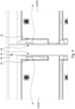
- Fig. 3 illustrates a sectional view of one of the battery packs 21 of the energy storage cabinet 20 shown in Fig. 1 .
- the battery pack 21 further includes a liquid filling device 60 connected to the housing 29.
- a liquid filling port 66 is formed at a position where the housing 29 and the liquid filling device 60 are connected.
- the liquid filling device 60 is configured to acquire the cooling liquid 27 from the liquid tank 25 mentioned above and is configured to fill the cooling liquid 27 into the housing 29.
- a lower edge 49 of the side opening 24 of the housing 29 is positioned below the electrodes 15 of the battery cells 12 in a vertical direction.
- a highest level 48 of the cooling liquid 27 filled into the housing 29 through the liquid filling port 66 is below the electrodes 15 of the battery cells 12.
- the cooling liquid 27 is prevented from contacting the electrodes 15 of the battery cells 12 to avoid short-circuiting of the battery cells 12.
- the liquid filling port 66 can be positioned below the lower edge 49 of the side opening 24 in the vertical direction.
- the lower edge 49 of the side opening 24 of the housing 29 is positioned below the bus bars 30 in the vertical direction.
- the highest level 48 of the cooling liquid 27 filled into the housing 29 is below the bus bars 30.
- the lower edge 49 of the side opening 24 of the housing 29 is positioned below the control boards 37 in the vertical direction.
- the highest level 48 of the cooling liquid 27 filled into the housing 29 is below the control boards 37.
- the liquid filling device 60 includes a liquid pipe 64.
- One end of the liquid pipe 64 is connected the housing 29 of the battery pack 21 via the liquid filling port 66, and the other end of the liquid pipe 64 can be connected to the liquid tank 25 mentioned above to acquire the cooling liquid.
- the liquid filling device 60 further includes a valve 65 disposed on the liquid pipe 64.
- the valve 65 can switch between an open state and a close state. When the valve 65 is in the open state, the valve 65 allows the liquid pipe 64 to deliver the cooling liquid to the housing 29. When the valve 65 is in the close state, the valve 65 blocks the liquid pipe 64 such that the liquid pipe 64 cannot deliver the cooling liquid to the housing 29.
- the valve 65 may also control the flow rate of the cooling liquid.
- the valve 65 can be a solenoid valve.
- the control device 90 mentioned above can control opening and closing of the valve 65, and can also control the degree the valve 65 is opened.
- the valve 65 is configured to allow or block delivery of the cooling liquid to the housing 29 by the liquid pipe 64 based on information about a temperature of the battery pack 21.
- the aforementioned control device 90 of the energy storage cabinet is configured to receive temperature information from the temperature sensor 38 or the battery management system on the control board 37.
- the temperature information is indicative of a temperature at one or more locations within the battery pack 21.
- the control device is further configured to determine whether the battery pack 21 is overheating based on the temperature information. If the battery pack 21 is overheating, then the control device is configured to instruct the liquid filling device 60 to fill the cooling liquid into the housing 29 of the battery pack 21.
- the control device may be communicably connected to the valve 65. If the battery pack 21 is overheating, then the control device can instruct the valve 65 to open by sending a control signal to the valve 65.
- the aforementioned control device 90 of the energy storage cabinet 20 is configured to determine, based on the temperature information, whether the temperature of the battery pack 21 exceeds a first threshold value or whether a temperature change rate of the battery pack 21 exceeds a second threshold value. If the temperature of the battery pack 21 exceeds the first threshold value or the temperature change rate of the battery pack 21 exceeds the second threshold value, then the control device is configured to instruct the liquid filling device 60 to fill the cooling liquid into the housing 29 of the battery pack 21.
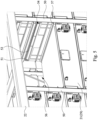
- Fig. 5 illustrates a partially enlarged view of the slots 56 of the energy storage cabinet 20 shown in Fig. 1 .
- Two adjacent supports 50 of the frame 22 define multiple slots 56.
- the battery packs 21 are detachably disposed in the slots 56.
- Fig. 5 shows some of the battery packs 21 being ejected from the slots 56.
- At least one of the supports 50 can include at least one guiding rail 57 disposed on a lateral surface of the supports 50.
- the guiding rail 57 is configured to slidably engage the housing 29 of the battery pack 21.
- At least one of the supports 50 can include at least one second duct structure 51.
- Each second duct structure 51 surrounds a respective side opening 54 of the supports 50 and projects from an outer wall of the supports 50.
- the second duct structure 51 is coupled to the first duct structure 41 mentioned above, such that the side opening 24 of the housing 29 of the battery pack 21 communicates with a respective side opening 54 of the supports 50.
- the second duct structure 51 has a second sloping edge 52.
- the first sloping edge 42 of the first duct structure 41 mentioned above and the second sloping edge 52 of the second duct structure 51 have complementary shapes and abut against each other, such that the gap between the first duct structure 41 and the second duct structure 51 is minimized. With the first sloping edge 42 and the second sloping edge 52, the battery packs 21 can be smoothly inserted into or ejected from slots 56.
- the energy storage cabinet of the present disclosure includes a liquid tank configured to store a cooling liquid. At least one of the battery packs of the energy storage cabinet is provided with a liquid filling device.
- the liquid filling device is connected to the liquid tank and is configured to fill the cooling liquid into the housing of the battery pack to cope with the situation where some or all of the battery cells of the battery pack fail and the temperature goes out of control or even causes fire.
- the housing has at least one side opening which can allow excessive cooling liquid to be discharged out of the housing. In the vertical direction, a lower edge of the side opening of the housing is at a position below the electrodes of the battery cells. Thus, the cooling liquid is prevented from contacting the electrodes of the battery cells to avoid short-circuiting of the battery cells.
Landscapes
- Chemical & Material Sciences (AREA)
- Chemical Kinetics & Catalysis (AREA)
- Electrochemistry (AREA)
- General Chemical & Material Sciences (AREA)
- Engineering & Computer Science (AREA)
- Manufacturing & Machinery (AREA)
- Inorganic Chemistry (AREA)
- Automation & Control Theory (AREA)
- Secondary Cells (AREA)
- Battery Mounting, Suspending (AREA)
- Connection Of Batteries Or Terminals (AREA)
Applications Claiming Priority (1)
| Application Number | Priority Date | Filing Date | Title |
|---|---|---|---|
| US202363534181P | 2023-08-23 | 2023-08-23 |
Publications (2)
| Publication Number | Publication Date |
|---|---|
| EP4513623A2 true EP4513623A2 (de) | 2025-02-26 |
| EP4513623A3 EP4513623A3 (de) | 2025-03-19 |
Family
ID=92538402
Family Applications (3)
| Application Number | Title | Priority Date | Filing Date |
|---|---|---|---|
| EP24196074.9A Pending EP4513658A1 (de) | 2023-08-23 | 2024-08-23 | Batteriepack und batteriezellenverbindungskomponente davon |
| EP24196071.5A Pending EP4513623A3 (de) | 2023-08-23 | 2024-08-23 | Energiespeicherschrank und batteriepack dafür |
| EP24196072.3A Active EP4513624B1 (de) | 2023-08-23 | 2024-08-23 | Energiespeicherschrank |
Family Applications Before (1)
| Application Number | Title | Priority Date | Filing Date |
|---|---|---|---|
| EP24196074.9A Pending EP4513658A1 (de) | 2023-08-23 | 2024-08-23 | Batteriepack und batteriezellenverbindungskomponente davon |
Family Applications After (1)
| Application Number | Title | Priority Date | Filing Date |
|---|---|---|---|
| EP24196072.3A Active EP4513624B1 (de) | 2023-08-23 | 2024-08-23 | Energiespeicherschrank |
Country Status (4)
| Country | Link |
|---|---|
| US (3) | US20250070314A1 (de) |
| EP (3) | EP4513658A1 (de) |
| JP (3) | JP7829637B2 (de) |
| TW (3) | TWI890563B (de) |
Family Cites Families (35)
| Publication number | Priority date | Publication date | Assignee | Title |
|---|---|---|---|---|
| JPH11238530A (ja) * | 1998-02-23 | 1999-08-31 | Matsushita Electric Ind Co Ltd | モジュール電池の冷却方法および製造方法 |
| JP2000310212A (ja) * | 1999-04-23 | 2000-11-07 | Masuda Shoten:Kk | クリップナット |
| JP2005019134A (ja) * | 2003-06-25 | 2005-01-20 | Shin Kobe Electric Mach Co Ltd | 鉛蓄電池システム |
| JP2008117708A (ja) * | 2006-11-07 | 2008-05-22 | Toyota Motor Corp | バッテリパック構造 |
| JP5078463B2 (ja) * | 2007-06-29 | 2012-11-21 | 三洋電機株式会社 | 車両用の電源装置 |
| JP5159233B2 (ja) * | 2007-09-28 | 2013-03-06 | 株式会社東芝 | バスバー |
| JP4875718B2 (ja) * | 2009-01-21 | 2012-02-15 | 株式会社井上製作所 | 可撓導体および可撓導体の製造方法 |
| DE102009033370B4 (de) * | 2009-07-16 | 2011-12-15 | Taller Gmbh | Stromschiene mit Kompensationsabschnitt |
| TWI466359B (zh) * | 2010-08-23 | 2014-12-21 | Sumitomo Heavy Industries | Battery inspection device |
| JP6261975B2 (ja) * | 2013-12-11 | 2018-01-17 | 株式会社東芝 | 発熱体収容装置 |
| JP5874156B2 (ja) * | 2014-01-31 | 2016-03-02 | 大阪フォーミング株式会社 | クリップナット |
| CN104836045A (zh) * | 2014-02-10 | 2015-08-12 | 康舒科技股份有限公司 | 服务器电源系统及其挠性连接器 |
| US10269466B2 (en) * | 2016-05-17 | 2019-04-23 | Lear Corporation | High efficiency bus bar for use in conducting an alternating current and method for manufacturing same |
| US9853435B1 (en) * | 2016-08-29 | 2017-12-26 | Ford Global Technologies, Llc | Busbar thermal management assembly and method |
| JP2020057449A (ja) * | 2017-01-31 | 2020-04-09 | 三洋電機株式会社 | ラック型の電源装置 |
| CN207517757U (zh) * | 2017-11-21 | 2018-06-19 | 中航锂电(洛阳)有限公司 | 储能用恒温机柜及其柜体 |
| CN110120570B (zh) * | 2018-02-07 | 2020-09-08 | 北京好风光储能技术有限公司 | 一种热均衡式双极性电池堆 |
| DE102018103706A1 (de) * | 2018-02-20 | 2019-08-22 | Dr. Ing. H.C. F. Porsche Aktiengesellschaft | Ladesystem mit integriertem Kühlmittelspeicher |
| JP7033730B2 (ja) * | 2018-07-11 | 2022-03-11 | パナソニックIpマネジメント株式会社 | 冷却装置、電池温度調整システム及び車両 |
| CN209104249U (zh) * | 2018-11-12 | 2019-07-12 | 宁德时代新能源科技股份有限公司 | 电池模组 |
| CN110061162B (zh) * | 2019-03-22 | 2023-04-07 | 中国电力科学研究院有限公司 | 具有散热与消防功能的储能电池簇 |
| KR102767147B1 (ko) * | 2019-07-22 | 2025-02-11 | 주식회사 엘지에너지솔루션 | 전력 저장 장치 |
| JP2021077571A (ja) * | 2019-11-12 | 2021-05-20 | 株式会社デンソー | 電池パック |
| CN111029496B (zh) * | 2019-11-20 | 2022-04-22 | 江苏科技大学 | 一种可高效散热的储能电池散热支架 |
| BR102020003216A2 (pt) * | 2020-02-14 | 2021-08-31 | Melquisedec Francisquini | Barramento condutor tubular senoidal |
| KR102650084B1 (ko) * | 2020-03-04 | 2024-03-20 | 주식회사 엘지에너지솔루션 | 배터리 랙 및 이러한 배터리 랙을 포함하는 전력 저장 장치 |
| US11895807B2 (en) * | 2020-05-28 | 2024-02-06 | Google Llc | Thermal management of battery units on data center racks |
| CN115692912A (zh) * | 2021-07-30 | 2023-02-03 | 华为数字能源技术有限公司 | 储能装置 |
| KR102856932B1 (ko) * | 2022-02-08 | 2025-09-05 | 주식회사 엘지에너지솔루션 | 배터리 랙 및 이를 포함하는 전력 저장 장치 |
| CN219419160U (zh) * | 2022-11-09 | 2023-07-25 | 万物新能(深圳)科技有限公司 | 一种冷却与消防一体化储能设备 |
| CN115775933B (zh) * | 2022-12-27 | 2025-12-23 | 双一力(宁波)电池有限公司 | 一种风冷储能柜 |
| CN116526001A (zh) * | 2023-04-12 | 2023-08-01 | 深圳市广安电力设备有限公司 | 一种具有温控功能的储能柜 |
| CN116365103A (zh) * | 2023-04-28 | 2023-06-30 | 杭州鹏成新能源科技有限公司 | 一种浸没式液冷储能电池包热交换装置 |
| CN116581429B (zh) * | 2023-07-12 | 2023-10-13 | 深圳海辰储能控制技术有限公司 | 储能模组和用电设备 |
| CN118040199A (zh) * | 2024-01-18 | 2024-05-14 | 广东奥丰新能源发展有限公司 | 浸没式储能包、储能簇、储能厢、储能系统及其工作方法 |
-
2024
- 2024-08-23 US US18/813,051 patent/US20250070314A1/en active Pending
- 2024-08-23 EP EP24196074.9A patent/EP4513658A1/de active Pending
- 2024-08-23 US US18/813,034 patent/US20250070297A1/en active Pending
- 2024-08-23 TW TW113131726A patent/TWI890563B/zh active
- 2024-08-23 JP JP2024143474A patent/JP7829637B2/ja active Active
- 2024-08-23 EP EP24196071.5A patent/EP4513623A3/de active Pending
- 2024-08-23 EP EP24196072.3A patent/EP4513624B1/de active Active
- 2024-08-23 JP JP2024141798A patent/JP7746492B2/ja active Active
- 2024-08-23 US US18/813,049 patent/US20250070398A1/en active Pending
- 2024-08-23 JP JP2024141778A patent/JP2025031678A/ja active Pending
- 2024-08-23 TW TW113131728A patent/TW202510400A/zh unknown
- 2024-08-23 TW TW113131730A patent/TWI896305B/zh active
Also Published As
| Publication number | Publication date |
|---|---|
| EP4513658A1 (de) | 2025-02-26 |
| US20250070297A1 (en) | 2025-02-27 |
| US20250070314A1 (en) | 2025-02-27 |
| EP4513624A2 (de) | 2025-02-26 |
| TWI890563B (zh) | 2025-07-11 |
| TWI896305B (zh) | 2025-09-01 |
| JP2025031680A (ja) | 2025-03-07 |
| JP2025031697A (ja) | 2025-03-07 |
| JP7829637B2 (ja) | 2026-03-13 |
| EP4513624A3 (de) | 2025-03-05 |
| US20250070398A1 (en) | 2025-02-27 |
| JP2025031678A (ja) | 2025-03-07 |
| EP4513623A3 (de) | 2025-03-19 |
| JP7746492B2 (ja) | 2025-09-30 |
| TW202510399A (zh) | 2025-03-01 |
| TW202508865A (zh) | 2025-03-01 |
| TW202510400A (zh) | 2025-03-01 |
| EP4513624B1 (de) | 2025-12-17 |
Similar Documents
| Publication | Publication Date | Title |
|---|---|---|
| KR102338516B1 (ko) | 리튬이온배터리 화재 안전을 위한 보호 장치 | |
| US11069937B2 (en) | Enclosing element, enclosing module, storage module and arrangement for providing electrical energy and a transport vehicle containing the storage module or the arrangement for providing electrical energy | |
| KR102586103B1 (ko) | 배터리 시스템, 배터리 시스템 내부 누출 검출 방법, 및 배터리 시스템을 포함하는 차량 | |
| EP4593178A1 (de) | Energiespeichervorrichtung | |
| KR101937530B1 (ko) | 차량용 배터리 모듈의 충전 및 방전 장치 | |
| US20240322322A1 (en) | Battery pack | |
| KR20210016228A (ko) | 에너지저장시스템의 환경 모니터링 방법 및 장치 | |
| US10020546B2 (en) | Device for managing an accumulator | |
| US12456771B2 (en) | Battery rack, power storage device, and data storage device | |
| KR102114205B1 (ko) | 배터리 장치 | |
| EP4513623A2 (de) | Energiespeicherschrank und batteriepack dafür | |
| CN218101376U (zh) | 锂离子单体电池和测试电源 | |
| KR20240131184A (ko) | 배터리 팩 및 이를 포함하는 차량 | |
| KR20230040607A (ko) | 화재 예방 기능을 구비한 배터리 모듈 및 배터리 모듈 화재 예방 방법 | |
| JP4660282B2 (ja) | 電源装置 | |
| CN205160121U (zh) | 一种使用寿命长的低损耗锂电池 | |
| CN222749634U (zh) | 一种电池储能系统 | |
| KR102082213B1 (ko) | 배터리 모듈 체크 장치 | |
| US20250273765A1 (en) | Battery system with integrated cooling manifold | |
| KR102631053B1 (ko) | 차량용 배터리 | |
| RU2799472C1 (ru) | Тяговая аккумуляторная батарея на основе литий-титанат оксидных ячеек для беспилотных высокоавтоматизированных транспортных средств | |
| RU2795445C1 (ru) | Тяговая аккумуляторная батарея на основе литий-железо-фосфатных ячеек для беспилотных высокоавтоматизированных транспортных средств | |
| CN222637510U (zh) | 一种隔爆型锂离子蓄电池电源 | |
| CN221612998U (zh) | 一种储能电池检修装置 | |
| CN114256558B (zh) | 一种大容量电池储能系统 |
Legal Events
| Date | Code | Title | Description |
|---|---|---|---|
| PUAI | Public reference made under article 153(3) epc to a published international application that has entered the european phase |
Free format text: ORIGINAL CODE: 0009012 |
|
| STAA | Information on the status of an ep patent application or granted ep patent |
Free format text: STATUS: THE APPLICATION HAS BEEN PUBLISHED |
|
| PUAL | Search report despatched |
Free format text: ORIGINAL CODE: 0009013 |
|
| AK | Designated contracting states |
Kind code of ref document: A2 Designated state(s): AL AT BE BG CH CY CZ DE DK EE ES FI FR GB GR HR HU IE IS IT LI LT LU LV MC ME MK MT NL NO PL PT RO RS SE SI SK SM TR |
|
| AK | Designated contracting states |
Kind code of ref document: A3 Designated state(s): AL AT BE BG CH CY CZ DE DK EE ES FI FR GB GR HR HU IE IS IT LI LT LU LV MC ME MK MT NL NO PL PT RO RS SE SI SK SM TR |
|
| RIC1 | Information provided on ipc code assigned before grant |
Ipc: H01M 50/209 20210101ALI20250212BHEP Ipc: H01M 10/6567 20140101ALI20250212BHEP Ipc: H01M 10/6556 20140101ALI20250212BHEP Ipc: H01M 10/6551 20140101ALI20250212BHEP Ipc: H01M 10/647 20140101ALI20250212BHEP Ipc: H01M 10/627 20140101ALI20250212BHEP Ipc: H01M 10/613 20140101AFI20250212BHEP |
|
| STAA | Information on the status of an ep patent application or granted ep patent |
Free format text: STATUS: REQUEST FOR EXAMINATION WAS MADE |
|
| 17P | Request for examination filed |
Effective date: 20250714 |