EP4509929A2 - Mechanische übertragungsvorrichtung für uhr - Google Patents
Mechanische übertragungsvorrichtung für uhr Download PDFInfo
- Publication number
- EP4509929A2 EP4509929A2 EP24222725.4A EP24222725A EP4509929A2 EP 4509929 A2 EP4509929 A2 EP 4509929A2 EP 24222725 A EP24222725 A EP 24222725A EP 4509929 A2 EP4509929 A2 EP 4509929A2
- Authority
- EP
- European Patent Office
- Prior art keywords
- wheel
- escapement
- axis
- blocker
- force
- Prior art date
- Legal status (The legal status is an assumption and is not a legal conclusion. Google has not performed a legal analysis and makes no representation as to the accuracy of the status listed.)
- Pending
Links
Images





Classifications
-
- G—PHYSICS
- G04—HOROLOGY
- G04B—MECHANICALLY-DRIVEN CLOCKS OR WATCHES; MECHANICAL PARTS OF CLOCKS OR WATCHES IN GENERAL; TIME PIECES USING THE POSITION OF THE SUN, MOON OR STARS
- G04B15/00—Escapements
- G04B15/06—Free escapements
- G04B15/08—Lever escapements
-
- G—PHYSICS
- G04—HOROLOGY
- G04B—MECHANICALLY-DRIVEN CLOCKS OR WATCHES; MECHANICAL PARTS OF CLOCKS OR WATCHES IN GENERAL; TIME PIECES USING THE POSITION OF THE SUN, MOON OR STARS
- G04B15/00—Escapements
- G04B15/06—Free escapements
-
- G—PHYSICS
- G04—HOROLOGY
- G04B—MECHANICALLY-DRIVEN CLOCKS OR WATCHES; MECHANICAL PARTS OF CLOCKS OR WATCHES IN GENERAL; TIME PIECES USING THE POSITION OF THE SUN, MOON OR STARS
- G04B15/00—Escapements
- G04B15/10—Escapements with constant impulses for the regulating mechanism
-
- G—PHYSICS
- G04—HOROLOGY
- G04B—MECHANICALLY-DRIVEN CLOCKS OR WATCHES; MECHANICAL PARTS OF CLOCKS OR WATCHES IN GENERAL; TIME PIECES USING THE POSITION OF THE SUN, MOON OR STARS
- G04B15/00—Escapements
- G04B15/14—Component parts or constructional details, e.g. construction of the lever or the escape wheel
-
- G—PHYSICS
- G04—HOROLOGY
- G04B—MECHANICALLY-DRIVEN CLOCKS OR WATCHES; MECHANICAL PARTS OF CLOCKS OR WATCHES IN GENERAL; TIME PIECES USING THE POSITION OF THE SUN, MOON OR STARS
- G04B19/00—Indicating the time by visual means
- G04B19/02—Back-gearing arrangements between gear train and hands
Definitions
- the invention relates to a method of operating a timepiece escapement device.
- the invention further relates to a timepiece escapement device.
- the invention further relates to a timepiece movement comprising such a device.
- the invention relates to a timepiece comprising such a device or such a timepiece movement.
- the invention also relates to a transmission device and a timepiece comprising such a transmission device.
- escapement devices such as the Swiss lever escapement or the Robin type escapement, described for example in the patent EP1122617B1 , typically include an escape wheel and a blocker.
- the escape wheel consists of a first escape pinion meshing with or taking part in the finishing gear train of a watch movement and an escape wheel designed to cooperate by contact with the blocker which is itself designed to cooperate by contact with an oscillator, in particular a sprung balance, in particular a roller pin of a sprung balance.
- the roller pin directly actuates the blocker, by means of a blocker fork, which itself acts directly against the escape wheel.
- Such escapement devices have relatively low efficiencies, of the order of 30% to 40%.
- the aim of the invention is to provide a mechanical transmission device and a clock escapement device making it possible to overcome the drawbacks mentioned above and to improve the mechanical transmission devices and clock escapement devices known from the prior art.
- the invention proposes a mechanical transmission device and an exhaust device with improved mechanical efficiency.
- a mechanical transmission device according to the invention is defined by claim 1.
- a timepiece relating to the invention is defined by claim 6.
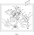
- a first embodiment of a timepiece 600 is described below with reference to the Figures 1 to 8 .
- the timepiece is for example a watch, in particular a wristwatch.
- the timepiece comprises a first embodiment of a watch movement 500, in particular a mechanical movement.
- the movement comprises a first variant of a first embodiment of an escapement device 400 arranged between a gear train and an oscillator 4, 5.
- the gear train is designed to connect a driving organ, such as a barrel, to the escapement.
- the gear train thus allows energy to be transmitted from the driving organ to the escapement.
- the escapement provides energy to the oscillator in order to maintain its oscillations.
- the oscillator is for example an oscillator of the type balance 4 - spiral 5.
- the balance is pivoted on an axis A4.
- the escapement device 400 mainly comprises a first escape wheel 1 pivoted about an axis A1, a second escape wheel 2 pivoted about an axis A2 and a blocker 3 pivoted about an axis A3.
- the first escape wheel, the second escape wheel and the blocker are shaped and arranged so that, in a release phase of the escapement device, a force from the blocker controlled by the oscillator 4, 5 is transmitted to the first escape wheel via the second escape wheel.
- a release phase notably comprises a phase of releasing the blocking means of the blocker from the teeth of the second wheel 2 under the control of the oscillator 4, 5, that is to say that the positions of the blocker are determined by the positions of the oscillator.
- the first escapement wheel 1 comprises a first escapement wheel 1a capable of acting, directly or not, on the clockwork oscillator.
- a first pinion 1b of the finishing gear train is rotationally integral with the first escapement wheel 1a, in particular is fixed on the first escapement wheel 1a, in particular is fixed coaxially on the first escapement wheel 1a.
- the second escapement wheel comprises a single second escapement pinion 2b.
- the escapement device is a direct impulse escapement device, the operating principle of which is similar to that of a Robin type escapement device.
- the latter may for example be designed to cooperate with a 4-spiral 5 balance type oscillator.
- the first escape wheel 1a is designed to directly actuate the balance 4-spiral 5 via one of its teeth which, during each impulse phase of the escapement device, acts against an impulse pallet 40b of a plate 40 of the balance 4.
- the balance receives, in the impulse phase, energy directly from the first escape wheel 1a. This avoids friction losses induced by the blockers of the indirect impulse escapement devices.
- the first escape wheel 1a is kinematically linked to the drive member of the clockwork movement via the first pinion 1b.
- the first escape wheel 1a is capable of being blocked by the blocker 3 via the second escape wheel 2b which is interposed between the first wheel 1 and the blocker 3.
- the arrangement of the blocker, the first escape wheel and the second escape wheel is such that the force between the second escape wheel and the blocker 3 is substantially lower than the force between the first escape wheel and the second escape wheel, during the release phases. More particularly, the arrangement of the blocker, the first escape wheel and the second escape wheel is such that the force between the second escape pinion 2b and the blocker 3 is lower than the force between the first escape wheel 1a and the second escape pinion 2b.
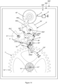
- FIG. 1 illustrates a first rest position of the escapement device.
- the plate 40 of balance wheel 4 rotates counterclockwise, and the pallet or pin 40a for releasing the plate 40 of balance wheel 4 moves away from a fork 3a of the blocker 3.
- a tooth 10a of the wheel 1a under the effect of the torque produced by the organ motor exerts a force F2 on a rest surface 200b of a tooth 20b of the pinion 2b.
- the force F2 which passes substantially close to the axis A2, creates a torque which tends to pivot the second pinion 2b in the counterclockwise direction, which generates a force F3 of support of a tooth 21b of the pinion 2b on a rest surface 30b of blocking means 3b, in particular a pallet 3b, of the blocker 3.
- the rest surface 30b is arranged so that the direction of the force F3 passes substantially through the axis A3.
- angle ⁇ formed between the force vector F2 and the half-line originating at the point of contact between the wheel 1a and the pinion 2b and passing through the axis A2 is substantially less than 50°, in particular less than 30°, or even less than 20°.
- FIG 2 illustrates the escapement device just after the release phase which follows the first rest position illustrated in the figure 1 .
- the balance wheel 40 plate 4 rotates clockwise.
- the release pallet 40a of the balance wheel 40 plate 40 came into contact with the fork 3a of blocker 3 and rotated the latter counterclockwise. This contact and action are maintained on the figure 2 .
- This action released tooth 21b of pinion 2b from rest surface 30b.
- the energy supplied by the balance during this release to overcome friction and to set the wheels and the blocker in motion is significantly lower than that supplied in a conventional Robin-type escapement device.
- the intensity of the force F3 is significantly lower than that of the support force F2.
- This intensity of the force F3 is minimized as much as possible if the inertias of the mobiles 1, 2 and of the blocker 3 are minimized as much as possible.
- the total diameter D2b of the pinion 2b is reduced as much as possible so as to reduce as much as possible the inertia of the pinion 2b, as well as the dimensions of the blocker 3.
- the total diameter D2b of the pinion 2b is significantly less than the total diameter D1a of the first wheel 1a.
- the total diameter D2b of the pinion 2b is less than 30% of the total diameter D1a of the first wheel 1a, or even less than 20% of the total diameter D1a of the first wheel 1a.
- the pinion 2b rotates counterclockwise.
- the tooth 22b of this pinion approaches the rest surface 30c of second blocking means 3c of the blocker 3 and rests on this surface in a second rest position.
- FIG. 3 illustrates this second rest position.
- the pallet 40a of the plate 40 of the balance wheel 4 moves away from the fork 3a of the blocker 3.
- the tooth 10a of the wheel 1a exerts a force F2* on the rest surface 200b of the tooth 20b of the pinion 2b.
- the force F2* which passes substantially close to the axis A2, creates a torque which tends to pivot the pinion 2b in the direction counterclockwise, which causes a support force F3* of the tooth 22b on the rest surface 30c of the pallet 3c of the blocker 3.
- the rest surface 30c is arranged so that the direction of the force F3* passes substantially through the axis A3.
- FIG 4 illustrates the escapement device just after the release phase which follows the second rest position illustrated in the figure 3 .
- the balance wheel rotates counterclockwise.
- the release pallet 40a of the balance wheel is in contact with the fork 3a of the blocker 3 and causes the latter to rotate clockwise. This contact and this action are maintained on the figure 4 .
- This action released tooth 22b of pinion 2b from rest surface 30c.
- the first escape wheel 1a accelerates and pushes, in particular pushes tangentially, the second pinion 2b in the counterclockwise direction.
- the tooth 11a of the escape wheel approaches the impulse pallet 40b of the balance wheel plate to transmit the energy to the balance wheel by the action of the tooth 11a on the pallet 40b during an impulse phase.
- the force transmitted from the tooth 11a to the pallet 40b is substantially tangential relative to the axes A1 and A4.
- figure 5 illustrates the position of the escapement at the end of the impulse phase.
- tooth 11a and pallet 40b are in contact by their respective ends and tooth 20b of pinion 2b approaches the rest surface 30b of pallet 3b of blocker 3.
- tooth 20b comes into contact with blocker 3 and tooth 10a comes into contact with second escapement wheel 2, we find our in the configuration illustrated by figure 1 .
- the escapement device has a very high efficiency, because it allows, on the one hand, to significantly reduce the energy supplied by the balance during disengagement, and on the other hand allows to increase the efficiency of the energy transmission thanks to a direct impulse from the escape wheel 1a to the balance, in particular by means of a force transmitted from the first escape wheel directly to the balance and which is substantially tangential.
- Another advantage of such an escapement device is the preservation, and therefore the optimization, of the isochronism of the sprung balance due to the low energy to be transmitted by the balance during disengagement.
- the rest surfaces 30b, 30c of the blocking means 3b, 3c of the blocker 3 are of concave shapes in order to guarantee the positioning accuracy of the teeth 20b of the pinion 2b on these surfaces.
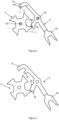
- these concave surfaces can each be formed by two inclined planes making an angle preferably between 120° and 170°, as illustrated in the figure 6 .
- the blocker 3 may also be provided with mechanical transmission means 3d, 3e, for example protuberances 3d, 3e, capable of rotating the pinion 2b in the opposite direction to that of the first escapement wheel 1a, in addition to the forces F2, F2*.
- these transmission means may exert an action complementary to those of the forces F2 and F2* to rotate the second escapement wheel in a counterclockwise direction.
- the actions are for example exerted by the blocker via the transmission means at the rest surfaces of the second escapement wheel.
- An example of an escapement device blocker according to the second variant is for example illustrated in FIG. figure 7 .
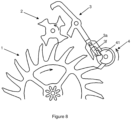
- the blocker 3 can also be provided with a dart 3f intended to cooperate with a complementary balance wheel plate 41 as shown in the figure. figure 8 , and this in order to prevent untimely movements of the blocker in the event of an impact.
- This third variant can be combined with either of the first and second variants.
- the geometries of the elements of the exhaust can be as described below.
- the first escapement wheel 1 comprises teeth 10a, in particular 20 teeth.
- the teeth are in the form of points.
- the teeth are oriented downstream (relative to their movement) in a direction making an angle of between 20 and 45° with the radial direction relative to the axis of the first mobile.
- the free end of each tooth may be bevel-shaped.
- the second escape wheel 2 comprises teeth 20b, in particular 4 teeth.
- the teeth extend substantially along an angular sector of approximately 45°.
- Each tooth comprises a rest surface 200b oriented to form an angle ⁇ of between 15° and 50°, or even between 20° and 45°, with the orthoradial direction relative to the axis A2 of the second wheel.
- the angle ⁇ is an acute angle measured between the tangent to the rest surface and an orthoradial vector O2 relative to the axis A2 and originating at the point of contact between the wheel 1a and the pinion 2b. This orientation makes it possible to create a slight torque tending to rotate the second wheel against the blocker in the rest and release phases.
- Each tooth is also limited by at least one lateral surface 202b oriented substantially radially relative to the axis A2.
- the blocker 3 comprises rest surfaces 30b, 30c.
- the rest surfaces of the blocker are oriented at least substantially orthoradially relative to the axis A3.
- one end of a tooth 10a bears against a rest surface 200b of a tooth 20b of the second escape wheel and a lateral surface 202b of another tooth 21b of the second wheel bears against one or other of the rest surfaces 30b, 30c of the blocker.
- a half-line originating from the axis A2 of the second escapement wheel and passing through the first point of contact where the first force F2 of the first escapement wheel is applied to the second escapement wheel and a half-line originating from the axis A2 of the second escapement wheel and passing through the axis A1 of the second escapement wheel form an angle greater than 10°, or even greater than 20°, or even greater than 30°.
- a half-line having as its origin the axis A1 of the first escapement wheel and passing through the axis A2 of the second escapement wheel; and a half-line having as its origin the axis A1 of the first escapement wheel and passing through the first point of contact where the first force F2 of the first escapement wheel is applied to the second escapement wheel form an angle greater than 5°, or even greater than 10°, or even greater than 20°.
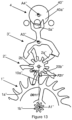
- a second embodiment of a 600', 600", 600* timepiece is described below with reference to Figures 9 to 15 .
- the timepiece is for example a watch, in particular a wristwatch.
- the timepiece comprises a second embodiment of a watch movement 500', 500", 500*, in particular a mechanical movement.
- the movement comprises a second embodiment of an escapement device 400', 400", 400* arranged between a gear train and an oscillator 4, 5.
- the gear train is designed to connect a driving organ, such as a barrel, to the escapement.
- the gear train thus allows energy to be transmitted from the driving organ to the escapement.
- the escapement provides energy to the oscillator in order to maintain its oscillations.
- the oscillator is for example an oscillator of the type balance 4 - spiral 5.
- the balance is pivoted on an axis A4', A4", A4*.
- the escapement device 400', 400", 400* mainly comprises a first escapement wheel 1', 1", 1* pivoted about an axis A1', A1", A1*, a second escapement wheel 2', 2", 2* pivoted about an axis A2', A2", A2* and a blocker 3', 3", 3* pivoted about an axis A3', A3", A3*.
- the first escapement wheel, the second escapement wheel and the blocker are shaped and arranged so that, in a release phase of the escapement device, a force from the blocker controlled by the oscillator 4, 5 is transmitted to the first escapement wheel via the second escapement wheel.
- the first escapement wheel comprises a first escapement wheel 1a', 1a", 1a* capable of acting indirectly on the clockwork oscillator.
- a first pinion 1b', 1b", 1b* of the finishing gear train is rotationally integral with the first escapement wheel 1a', 1a", 1a*, in particular is fixed to the first escapement wheel 1a, 1a", 1a*, in particular is fixed coaxially to the first escapement wheel 1a', 1a", 1a*.
- the escapement device is a direct impulse escapement device, the operating principle of which is similar to that of a Robin type escapement device. The latter may for example be designed to cooperate with a 4-spring balance 5 type oscillator.
- the second escapement wheel comprises a second escapement pinion 2b', 2b", 2b* and a second wheel 2a', 2a", 2a*.
- the second wheel 2a', 2a", 2a* is secured to the second escapement pinion 2b', 2b", 2b*, in particular the second wheel 2a', 2a", 2a* is fixed to the second escapement pinion 2b', 2b", 2b* or vice versa.
- the blocker cooperates with the second escapement pinion 2b', 2b", 2b* via the second escapement wheel 2a', 2a", 2a*, and vice versa.
- the second pinion 2b', 2b", 2b* is designed to cooperate directly with a first escapement wheel 1a', 1a", 1a* which is rotationally fixed to the first pinion 1b', 1b", 1b* of the finishing gear of the clockwork movement.
- the escapement device is of the direct impulse type. Its operating principle is similar to that of a Robin type escapement device.
- the latter may for example be designed to cooperate with an oscillator of the balance-spring type.
- the escapement device is distinguished from that of the first embodiment by the fact that the impulse to the sprung balance is produced by a tooth 20a' of the second escapement wheel 2a'.
- the exhaust device has an operation equivalent to that of the first embodiment.
- the second wheel 2a' has the same number of teeth as the second pinion 2b', namely six teeth.
- FIG 9 illustrates a rest position of such an escapement device, similar to that of the device according to the first embodiment illustrated by the figure 3 , which precedes a release phase.
- the tooth 10a' of the wheel 1a' exerts a force F20 on a rest surface 200b' of the tooth 20b' of the pinion 2b'.
- the force F20 which passes substantially close to the axis A2', creates a torque which tends to pivot the pinion 2b' in the counterclockwise direction, which causes a support force F30 of a tooth 20a' on a rest surface 30c' of the blocking means 3c' of the blocker 3'.
- the rest surface 30c' is arranged so that the direction of the force F30 passes substantially through the axis A3'.
- the energy supplied by the balance during the release phase to overcome friction and to set the wheels and the blocker in motion is significantly lower than that supplied in a conventional Robin-type escapement device.
- angle ⁇ ' formed between the force vector F20 and the half-line originating at the point of contact between the wheel 1a' and the pinion 2b' and passing through the axis A2' is substantially less than 50°, or even less than 30°, or even less than 20°.
- the total diameter D2b' of the pinion 2b' is reduced as much as possible so as to reduce as much as possible the inertia of the pinion 2b', as well as the dimensions of the blocker 3'.
- the total diameter D2b' of the pinion 2b' is substantially less than the total diameter D1a' of the first wheel 1a', in particular less than 50%, or even less than 40% of the total diameter D1a' of the first wheel 1a'.
- the tooth profile of the elements 1a' and 2b' can also be shaped so that the torque transmitted by the first wheel 1a' to the second pinion 2b' during the impulse phase is substantially greater than that transmitted during disengagement.
- an impulse surface 201b" of the second pinion 2b' is oriented so that the transmitted force F20' is substantially tangential to the trajectory of the point of contact between the wheel 1a' and the pinion 2b'.
- the force F20' is substantially normal to the half-line originating from the axis A1' and passing through the axis A2'.
- the torque C2i transmitted to the pinion 2b' during the impulse phase is substantially greater than the torque C2d transmitted to the pinion 2b' during the release phase.
- the energy to be provided by the balance during the release phase is minimized and the energy transmitted by the drive member during the impulse phase to the escapement device is maximized.
- Such an escapement device thus has the advantage of having a maximized efficiency with respect to the devices known escapement devices of the prior art, of the order of 120 to 160% with respect to average reference efficiencies of the order of 30 to 40%.
- Such a device also has the advantage of minimizing the disturbances of the oscillator, and thus makes it possible to implement an oscillator with optimized isochronism with respect to the oscillators cooperating with escapement devices known from the prior art.
- the geometries of the exhaust elements may be as described below.
- the first escapement wheel 1' comprises teeth 10a', in particular 20 teeth.
- the teeth are oriented downstream (relative to their movement) in a direction making for example an angle of between 20° and 45° with the radial direction relative to the axis A1' of the first wheel.
- the free end of each tooth may be in the shape of a bevel.
- the second escapement pinion 2b' comprises teeth 20b', in particular 6 teeth.
- the teeth extend substantially along an angular sector of approximately 30°.
- Each tooth comprises a rest surface 200b' oriented to form an angle ⁇ ' of between 15° and 50°, or even between 20° and 45°, with the orthoradial direction O2' relative to the axis A2' of the second wheel set.
- the angle ⁇ ' is an acute angle measured between the tangent to the rest surface and an orthoradial vector O2' relative to the axis A2' and originating at the point of contact between the wheel 1a' and the pinion 2b'. This orientation makes it possible to create a slight torque tending to rotate the second wheel set against the blocker in the rest and release phases.
- Each tooth is also limited by at least one lateral surface oriented substantially radially relative to the axis A2'. This at least one lateral surface is an impulse surface 201b'.
- the blocker 3 comprises rest surfaces 30b', 30c'.
- the rest surfaces are oriented at least substantially orthoradially relative to the axis A3' of the blocker.
- one end of a tooth 10a' bears against a rest surface 200b' of a tooth 20b' of the second escape wheel and one end of a tooth 20a' of the second wheel bears against a rest surface 30b', 30c' of the blocker.
- a half-line originating from the axis A2' of the second escapement wheel and passing through the first point of contact where the first force F20 of the first escapement wheel is applied to the second escapement wheel and a half-line originating from the axis A2' of the second escapement wheel and passing through the axis A1' of the second escapement wheel form an angle greater than 10°, or even greater than 20°, or even greater than 30°.
- a half-straight line having as its origin the axis A1' of the first escapement wheel and passing through the axis A2' of the second escapement wheel; and a half-straight line originating from the axis A1' of the first escapement wheel and passing through the first point of contact where the first force F20 of the first escapement wheel is applied to the second escapement wheel form an angle greater than 5°, or even greater than 10°, or even greater than 20°.
- the escapement device is of the indirect impulse type. Its general operating principle is similar to that of a Swiss lever escapement device.
- the escapement device according to the second variant of the second embodiment may, for example, be designed to cooperate with an oscillator of the sprung balance type.
- Such an escapement device is distinguished from that of the first variant of the second embodiment by the fact that the impulse to the sprung balance is produced by means of a 3" blocker whose fork 3a" is designed to cooperate exclusively with a 4" balance, in particular a 40" balance plate, in particular a 40a" balance plate pin.
- FIG. 12 illustrates a rest position of such an escapement device which precedes a release phase.
- a tooth 10a" of the wheel 1a under the effect of the torque of the drive member, exerts a force F21 on a rest surface 200b" of a tooth 20b" of the pinion 2b".
- the force F21 which passes substantially close to the axis A2", creates a torque which tends to pivot the pinion 2b" in the counterclockwise direction, which causes a support force F31 of a tooth 20a" on a rest surface 30c" of blocking means 3c" of the blocker 3".
- the rest surface 30c" is arranged so that the direction of the force F31 passes substantially through the A3 axis".
- the energy supplied by the balance wheel during release to overcome friction and to set the wheels and the blocker in motion is therefore significantly lower than that supplied in a conventional Swiss lever type escapement device.
- angle ⁇ " formed between the force vector F21 and the half-line originating at the point of contact between the wheel 1a" and the pinion 2b" and passing through the axis A2" is significantly less than 50°, or even less than 30°, or even less than 20°.
- the total diameter D2b" of the pinion 2b" is reduced as much as possible so as to reduce as much as possible the inertia of the pinion 2b", as well as the dimensions of the blocker 3".
- the total diameter D2b" of the pinion 2b" is substantially less than the total diameter D1a" of the first wheel 1a", in particular less than 60% of the total diameter D1a" of the first escapement wheel 1a", or even less than 50% of the total diameter D1a" of the first escapement wheel 1a".
- the tooth profile of the elements 1a" and 2b" can also be shaped so that the torque transmitted by the first wheel 1a" to the second pinion 2b" during the impulse phase is significantly greater than that transmitted during disengagement.
- an impulse surface 201b" of the second pinion 2b" is oriented so that that the force F21' transmitted by the first escapement wheel to the second escapement wheel is substantially tangential to the trajectory of the point of contact between the wheel 1a" and the pinion 2b".
- the force F21' is substantially normal to the half-line originating from the axis A1" and passing through the axis A2".
- the torque C2i' transmitted to the pinion 2b" during the impulse phase is substantially greater than the torque C2d' transmitted to the pinion 2b" during the release phase.
- the energy to be provided by the balance during the release phase is minimized, and the energy transmitted by the drive member during the impulse phase to the escapement device is maximized.
- Such an escapement device thus has the advantage of exhibiting a maximized efficiency compared to the escapement devices known from the prior art, of the order of 120 to 160% compared to average reference efficiencies of the order of 30 to 40%.
- Such a device also has the advantage of minimizing the disturbances to the oscillator, and thus makes it possible to implement an oscillator with optimized isochronism with respect to the oscillators cooperating with escapement devices known from the prior art.
- the geometries of the exhaust elements may be as described below.
- the first escapement wheel 1" comprises teeth 10a", in particular 20 teeth.
- the teeth are oriented downstream (relative to their movement) in a direction making for example an angle of between 20° and 45° with the radial direction at the axis A1" of the first wheel.
- the free end of each tooth can be in the shape of a bevel.
- the second escapement pinion 2b" comprises teeth 20b", in particular 10 teeth.
- the teeth extend substantially along an angular sector of approximately 10°.
- Each tooth comprises a rest surface 200b" oriented to form an angle ⁇ " of between 15° and 50°, or even between 20° and 45°, with the orthoradial direction O2" relative to the axis A2" of the second mobile.
- the angle ⁇ " is an acute angle measured between the tangent to the rest surface and an orthoradial vector O2" relative to the axis A2" and originating at the point of contact between the wheel 1a and the pinion 2b. This orientation makes it possible to create a slight torque tending to rotate the second mobile against the blocker in the rest and release phases.
- Each tooth is also limited by two lateral surfaces oriented substantially radially relative to the axis A2". One of these two side surfaces is a 201b" impulse surface.
- the second escape wheel 2a" comprises teeth 20a", in particular 5 teeth.
- the teeth are in the form of arms.
- Each tooth comprises a rest surface 200a" oriented at least substantially radially relative to the axis A3" of the blocker when this tooth of the second wheel is in contact with the blocker.
- Each tooth is also limited by an impulse surface 201a" oriented at least substantially orthoradially relative to the axis A3" of the blocker when this tooth of the second wheel is in contact with the blocker.
- the blocker 3 comprises the rest surfaces 30b", 30c" oriented at least substantially orthoradially relative to the axis A3" of the blocker and the impulse surfaces 31b", 31c" oriented at least substantially radially relative to the axis A3" of the blocker.
- one end of a tooth 10a" bears against a rest surface 200b" of a tooth 20b" of the second pinion and a rest surface 200a" of a tooth 20a" of the second wheel bears against a rest surface 30b", 30c" of the blocker.
- a half-line originating from the axis A2" of the second escapement wheel and passing through the first point of contact where the first force F21 of the first escapement wheel is applied to the second escapement wheel and a half-line originating from the axis A2" of the second escapement wheel and passing through the axis A"1 of the second escapement wheel form an angle greater than 10°, or even greater than 20°, or even greater than 30°.
- one end of a tooth 10a" bears against an impulse surface 201b" of a tooth 20b" of the second pinion and an impulse surface 201a" of a tooth 20a" of the second wheel bears against an impulse surface 31b" of the blocker.
- the exhaust device has an operating principle similar to that of the device disclosed in the application for patent WO2013182243A1 . This is for example designed to cooperate with a balance-spring type oscillator.
- the impulse to the sprung balance is achieved by means of a 3* blocker, a fork 30a* of which is provided to cooperate exclusively with a balance 4, in particular a balance plate 40*, in particular a balance plate pin 40a*.
- a 3* blocker is made of two separate parts 30*, 31* kinematically linked to each other. The first part 30* is pivoted about an axis A30*.
- the first part 30* comprises the fork 30a*, locking means 30b* provided to act by contact with a toothing 20a* of the second wheel 2a*, as well as a toothing 30c* which is provided to mesh with a toothing 31c* of the second part 31*.
- the second part 31* is pivoted about an axis A31 *.
- the second part 31* also comprises locking means 31b* provided to act by contact with the toothing 20a* of the second wheel 2a*.
- FIG 14 illustrates a rest position of such an escapement device which precedes a release phase.
- a tooth 10a* of the wheel 1a* exerts a force F22 on a rest surface 200b* of a tooth 20b* of the pinion 2b*.
- the force F22 passes substantially close to the axis A2*.
- the force F22 creates a torque which tends to pivot the pinion 2b* in the counterclockwise direction, which causes a support force F32 of a tooth 20a* on a rest surface 300b* of the blocking means 30b* of the part 30* of the blocker 3*.
- the rest surface 300b* is arranged so that the direction of the force F32 passes substantially through the axis A30*.
- the energy supplied by the balance wheel during release to overcome friction and to set the wheels and the blocker in motion is significantly lower than that supplied in a conventional Swiss lever type escapement device.
- angle ⁇ * formed between the force vector F22 and the half-line originating at the point of contact between the wheel 1a* and the pinion 2b* and passing through the axis A2* is substantially less than 50°, in particular less than 30°, or even less than 20°.
- the total diameter D2b* of the pinion 2b* is reduced as much as possible so as to reduce as much as possible the inertia of the pinion 2b*, as well as the dimensions of the blocker 3*.
- the total diameter D2b* of the pinion 2b* is substantially less than the total diameter D1a* of the first wheel 1a*, in particular less than 30% of the total diameter D1a* of the first escapement wheel 1a*, or even less than 20% of the total diameter D1a* of the first escapement wheel 1a*.
- the tooth profile of the elements 1a* and 2b* can also be shaped so that the torque transmitted by the first wheel 1a* to the second pinion 2b* during the impulse phase is substantially greater than that transmitted during the release phase.
- an impulse surface 201b* of the second pinion 2b* is oriented so that the transmitted force F22' is substantially tangential to the trajectory of the point of contact between the wheel 1a* and the pinion 2b*.
- the force F22' is substantially normal to the half-line originating from the axis A1* and passing through the axis A2*.
- the torque C2i" transmitted to the pinion 2b* during the impulse phase is substantially greater than the torque C2d" transmitted to the pinion 2b* during the release phase.
- the energy to be provided by the balance during the release phase is minimized, and the energy transmitted by the drive member during the impulse phase to the escapement device is maximized.
- Such an escapement device thus has the advantage of exhibiting maximized efficiency compared with known escapement devices of the prior art, such as that disclosed in the document WO2013182243A1 .
- Such a device also has the advantage of minimizing disturbances to the oscillator, and thus makes it possible to implement an oscillator with optimized isochronism with respect to the oscillators cooperating with escapement devices known from the prior art.
- the geometries of the exhaust elements may be as described below.
- the first escapement wheel 1* comprises 10a* teeth, in particular 40 teeth.
- the teeth have, for example, involute profiles or have substantially involute profiles.
- the second escapement pinion 2b* comprises teeth 20b*, in particular 6 teeth.
- the teeth extend substantially along an angular sector of approximately 30°.
- Each tooth comprises a rest surface 200b* oriented to form an angle ⁇ * of between 10° and 50°, or even between 20° and 35°, with the orthoradial direction O2* relative to the axis A2* of the second mobile.
- the angle ⁇ * is an acute angle measured between the tangent to the rest surface and an orthoradial vector O2* relative to the axis A2 and originating at the point of contact between the wheel 1a and the pinion 2b*. This orientation makes it possible to create a slight torque tending to rotate the second mobile against the blocker in the rest and release phases.
- Each tooth is also limited by two lateral surfaces oriented substantially radially relative to the axis A2*. One of these two lateral surfaces is an impulse surface 201b*
- the blocker 3* comprises rest surfaces 300b*, 310b* oriented at least substantially orthoradially relative to the axis A3* of the blocker and impulse surfaces 301b*, 311b* oriented at least substantially radially relative to the axis A3* of the blocker.
- a flank of a tooth 10a* bears against a rest surface 200b* of a tooth 20b* of the second pinion and an end 200a* of a tooth 20a* of the second wheel bears against a rest surface 310b*, 300b* of the blocker.
- a half-line having as its origin the axis A2* of the second escapement wheel and passing through the first point of contact where the first force F22 of the first escapement wheel is applied to the second escapement wheel and a half-line having as its origin the axis A2* of the second escapement wheel and passing through the axis A1* of the second mobile escapement forms an angle greater than 10°, or even greater than 20°, or even greater than 30°.
- a half-line having as its origin the axis A1* of the first escapement wheel and passing through the axis A2* of the second escapement wheel; and a half-line having as its origin the axis A1* of the first escapement wheel and passing through the first point of contact where the first force F22 of the first escapement wheel is applied to the second escapement wheel form an angle greater than 5°, or even greater than 10°, or even greater than 20°.
- the flank of a tooth 10a* bears against an impulse surface 201b* of a tooth 20b* of the second pinion and an end 200a* of a tooth 20a* of the second wheel bears against an impulse surface 301b*, 311b* of the blocker.
- the first and second escapement mobiles and the blocker are preferably made of a low-density material, for example silicon or a silicon alloy.
- the latter are preferably coated with a layer of SiO2 or Si4N3 in particular to reinforce their mechanical strengths and to optimize the tribology of the device.
- Such a device may, for example, not require lubrication.
- the rest surfaces of the blocking means of the blocker are of shapes concave in order to guarantee the positioning precision of the teeth of the second mobile 2, 2', 2", 2* on these surfaces.
- These concave surfaces are formed for example by two inclined planes making for example an angle preferably between 120° and 170°.
- the blocker may comprise mechanical transmission means capable of rotating the second escapement wheel in the opposite direction to that of the first escapement wheel.
- These means may consist of protuberances or teeth acting by contact on the second escapement wheel, in particular on impulse surfaces or on rest surfaces of the second escapement wheel.
- the blocker may comprise a dart provided to cooperate with a complementary balance plate, in order to prevent untimely movements of the blocker in the event of an impact.
- the escapement device is provided to maintain the oscillations of the clockwork oscillator in an optimized manner. As seen previously, the device makes it possible to minimize the energy to be provided by the oscillator during the release phase, i.e. when the oscillator actuates the blocker while an escape wheel is blocked in rotation by the blocker.
- the exhaust device has the advantage of having a maximized efficiency compared to the exhaust devices known from the prior art. Such a device also has the advantage of minimizing the disturbances of the oscillator, and thus makes it possible to implement an isochronism oscillator optimized with respect to the oscillators cooperating with escapement devices known from the prior art.
- the escapement device is such that it transmits from the first escapement wheel set to the second escapement wheel set a variable torque depending on whether it is in a release phase or in an impulse phase. The torque transmitted from the first escapement wheel set to the second escapement wheel set in the release phase is less than that transmitted from the first escapement wheel set to the second escapement wheel set in the impulse phase.
- the torque transmitted from the first escapement wheel set to the second escapement wheel set in the impulse phase may be constant or substantially constant.
- the torque transmitted from the first escapement wheel set to the second escapement wheel set in the release phase may be constant or substantially constant.
- the torque transmitted from the first escapement wheel to the second escapement wheel in the release phase may be equal or substantially equal to the torque transmitted from the first escapement wheel to the second escapement wheel in the rest phase.
- the first escapement wheel and the second escapement wheel may form a mechanical transmission device for a timepiece intended to transmit a torque, in particular intended to transmit a variable torque and/or coming from a barrel.
- the first escapement wheel and the second escapement wheel may be part of a mechanical transmission device for a timepiece intended to transmit a torque, in particular intended to transmit a variable torque and/or coming from a barrel.
- the escapement device is preferably such that in the release phase, the blocker acts directly against the second escapement wheel which is kinematically linked to the first escapement wheel.
- the escapement device 400; 400'; 400"; 400* preferably comprises a first escapement wheel 1; 1'; 1"; 1*, a second escapement wheel 2; 2'; 2"; 2* and a blocker 3; 3'; 3"; 3*.
- the second escapement wheel is preferably interposed between the first escapement wheel and the blocker, in particular the second escapement wheel can cooperate by contact with the first escapement wheel on the one hand and with the blocker on the other hand.
- the first escapement wheel, the second escapement wheel and the blocker are preferably shaped and arranged so that in the release phase of the escapement device, a force from the blocker controlled by the oscillator 4, 5 is transmitted to the first escapement wheel via the second escapement wheel.
- the first escapement wheel, the second escapement wheel and the blocker are preferably shaped and arranged so that in the release phase of the escapement device, a first force from the first escapement wheel is applied to the second escapement wheel and a second force from the blocker is applied to the second escapement wheel, the intensity of the second force being less than the intensity of the first force, in particular the intensity of the second effort being less than 0.5 times, or even less than 0.3 times, or even less than 0.2 times, the intensity of the first effort.
- the second escapement wheel 2; 2'; 2"; 2* may be a second pinion 2b or the second escapement wheel 2'; 2"; 2* may comprise a second pinion 2b'; 2b"; 2b* and a second wheel 2a'; 2a"; 2a*.
- the second escape wheel 2; 2';2"; 2* may comprise a second pinion 2b';2b"; 2b*, the second pinion being arranged to cooperate with the first escape wheel, the first escape wheel, in particular a first wheel of the first escape wheel, having a larger diameter, in particular more than 1.5 times larger, or even more than 2 times larger, than the diameter of a second pinion of the second escapement wheel 2; 2';2"; 2*.
- the second wheel may comprise impulse surfaces 201a" oriented at least substantially orthoradially relative to the axis A2; A2';A2"; A2* of the second wheel and/or rest surfaces 200a" oriented at least substantially radially to the axis of the second wheel A2; A2';A2"; A2* and/or the second pinion may comprise impulse surfaces 201b';201b"; 201b* oriented at least substantially radially relative to the axis of the second wheel A2; A2';A2"; A2* and/or rest surfaces 200b; 200b';200b”; 200b* oriented at an angle ⁇ ; ⁇ '; ⁇ "; ⁇ * between 15° and 50°, or even between 20° and 45°, between the tangent to the rest surface and a orthoradial vector O2; O2';O2"; O2* relative to the axis of the second mobile A2; A2';A2"; A2*
- the watch movement 500; 500'; 500"; 500* may comprise an escapement device as described above, in particular may comprise the finishing gear 1b'; 1b"; 1b*, the oscillator 4, 5 and an escapement device as described above.
- the escapement device is interposed between the finishing gear and the oscillator.
- the timepiece 600; 600'; 600"; 600* may comprise an escapement device as described above or a watch movement as described above or a watch transmission device as described above.
- the intensity of the second effort may be lower than the intensity of the first effort, in particular the intensity of the second effort may be lower than 0.5 times, or even less than 0.3 times, or even less than 0.2 times, the intensity of the first effort.
- the method may comprise an impulse phase in which the first escapement wheel applies, directly to the oscillator or directly to the second escapement wheel, a third force directed substantially orthoradially relative to the axis of the first escapement wheel or to the axis of the second escapement wheel or to the axis of the oscillator.
- the method may comprise an impulse phase in which the second escapement wheel applies, directly to the oscillator or directly to the blocker, a fourth force directed substantially orthoradially relative to the axis of the second escapement wheel or to the axis of the blocker or to the axis of the oscillator.
- the method may include an impulse phase in which the intensity of the torque transmitted from the first escapement wheel to the second escapement wheel or to an oscillator during the impulse phase is greater than 1.5 times, or even greater than 2 times, the intensity of the torque transmitted from the first escapement wheel to the second escapement wheel during a release phase.
- mobile we mean, throughout this document, a wheel or pinion or an assembly of wheel(s) and/or pinion(s).
- wheel we mean, throughout this document, any rotating toothed organ whose function is to transmit torque, force, or movement.
- pinion we mean, throughout this document, any rotating toothed member whose function is to transmit torque, force, or movement, whose diameter and/or number of teeth is significantly less than those of the wheel with which it meshes or with which it is integral in rotation.
- angles mentioned are oriented angles.
- the positive direction of orientation of these angles is the direction of rotation of the second escapement wheel when the escapement device is in operation.
- this positive direction of orientation of the angles is the trigonometric or counterclockwise direction.
- radial direction relative to an axis we mean, throughout this document, any direction perpendicular to this axis and passing through this axis.
- the radial vector is along this radial direction and oriented towards this axis.
- orthoradial direction relative to an axis we mean, throughout this document, any direction perpendicular to that axis and perpendicular to the radial direction relative to that axis.
- the orthoradial direction relative to an axis at a given point is also the tangential direction relative to that axis at the given point.
- the orthoradial vector is perpendicular to this radial direction and oriented such that the angle between the orthoradial vector and the radial vector is an oriented angle of +90°.
- direction substantially orthoradial relative to an axis we preferably mean, throughout this document, any direction orthoradial to this axis or any direction forming an angle of less than 30°, or even less than 20°, with a direction exactly orthoradial relative to this axis.
- direction substantially radial relative to an axis we preferably mean, throughout this document, any direction radial to this axis or any direction forming an angle of less than 30°, or even less than 20°, with a direction exactly radial relative to this axis.
- orientation of a surface is preferably defined by the direction tangent to this surface in the plane perpendicular to the pivot axes of the escapement wheels and/or the blocker.
- impulse surface of the second escapement wheel we preferably mean, throughout this document, any surface of the second escapement wheel likely to be in contact with the first escapement wheel or with the blocker during an impulse phase of the escapement device.
- resting surface of the second escapement wheel we preferably mean, throughout this document, any surface of the second escapement wheel likely to be in contact with the first escapement wheel or with the blocker during a resting phase or a release phase of the escapement device.
- impulse surface of the blocker we preferably mean, throughout this document, any surface of the blocker likely to be in contact with the second escapement wheel during an impulse phase of the escapement device.
- resting surface of the blocker we preferably mean, throughout this document, any surface of the blocker likely to be in contact with the second escapement wheel during a resting phase or a release phase of the escapement device.
- escapement wheel we preferably mean, throughout this document, any wheel for transmitting a force from the gear train to the blocker, the wheel being shaped and/or arranged so that the direction of the force that it transmits varies, in particular varies significantly, during an escapement cycle.
Landscapes
- Physics & Mathematics (AREA)
- General Physics & Mathematics (AREA)
- Transmission Devices (AREA)
- Gears, Cams (AREA)
- Mechanical Operated Clutches (AREA)
Applications Claiming Priority (3)
| Application Number | Priority Date | Filing Date | Title |
|---|---|---|---|
| CH18872015 | 2015-12-21 | ||
| EP16819920.6A EP3394682B1 (de) | 2015-12-21 | 2016-12-21 | Hemmvorrichtung für uhr und betriebsverfahren solch einer vorrichtung |
| PCT/EP2016/082258 WO2017109004A1 (fr) | 2015-12-21 | 2016-12-21 | Dispositif d'échappement horloger et procédé de fonctionnement d'un tel dispositif |
Related Parent Applications (2)
| Application Number | Title | Priority Date | Filing Date |
|---|---|---|---|
| EP16819920.6A Division-Into EP3394682B1 (de) | 2015-12-21 | 2016-12-21 | Hemmvorrichtung für uhr und betriebsverfahren solch einer vorrichtung |
| EP16819920.6A Division EP3394682B1 (de) | 2015-12-21 | 2016-12-21 | Hemmvorrichtung für uhr und betriebsverfahren solch einer vorrichtung |
Publications (2)
| Publication Number | Publication Date |
|---|---|
| EP4509929A2 true EP4509929A2 (de) | 2025-02-19 |
| EP4509929A3 EP4509929A3 (de) | 2025-04-23 |
Family
ID=57681594
Family Applications (2)
| Application Number | Title | Priority Date | Filing Date |
|---|---|---|---|
| EP24222725.4A Pending EP4509929A3 (de) | 2015-12-21 | 2016-12-21 | Mechanische übertragungsvorrichtung für uhr |
| EP16819920.6A Active EP3394682B1 (de) | 2015-12-21 | 2016-12-21 | Hemmvorrichtung für uhr und betriebsverfahren solch einer vorrichtung |
Family Applications After (1)
| Application Number | Title | Priority Date | Filing Date |
|---|---|---|---|
| EP16819920.6A Active EP3394682B1 (de) | 2015-12-21 | 2016-12-21 | Hemmvorrichtung für uhr und betriebsverfahren solch einer vorrichtung |
Country Status (5)
| Country | Link |
|---|---|
| US (1) | US11112758B2 (de) |
| EP (2) | EP4509929A3 (de) |
| JP (1) | JP6968814B2 (de) |
| CN (1) | CN108700845B (de) |
| WO (1) | WO2017109004A1 (de) |
Families Citing this family (9)
| Publication number | Priority date | Publication date | Assignee | Title |
|---|---|---|---|---|
| EP3547040B1 (de) * | 2018-03-29 | 2021-03-10 | Rolex Sa | Rad für uhrwerk |
| JP6566432B1 (ja) * | 2018-06-07 | 2019-08-28 | セイコーインスツル株式会社 | 定トルク機構、時計用ムーブメント及び時計 |
| WO2020043720A1 (fr) * | 2018-08-28 | 2020-03-05 | Rolex Sa | Echappement horloger |
| JP7485506B2 (ja) | 2018-10-12 | 2024-05-16 | ロレックス・ソシエテ・アノニム | 小型時計ムーブメント用の調速装置 |
| JP6908064B2 (ja) | 2019-03-14 | 2021-07-21 | セイコーエプソン株式会社 | 時計用部品、時計用ムーブメントおよび時計 |
| JP7238657B2 (ja) * | 2019-07-16 | 2023-03-14 | セイコーエプソン株式会社 | 時計用部品、時計用ムーブメントおよび時計 |
| CH718624B1 (fr) * | 2021-05-12 | 2024-05-31 | Rolex Sa | Échappement à énergie constante pour pièce d'horlogerie. |
| EP4105733B1 (de) * | 2021-06-15 | 2024-12-18 | Montres Breguet S.A. | Perkussionsschlagwerk, insbesondere für uhren |
| CN119310817A (zh) * | 2023-07-12 | 2025-01-14 | 劳力士有限公司 | 用于钟表的擒纵机构 |
Citations (2)
| Publication number | Priority date | Publication date | Assignee | Title |
|---|---|---|---|---|
| EP1122617B1 (de) | 2000-02-07 | 2007-08-01 | Audemars Piguet (Renaud et Papi) SA | Verriegelungsvorrichtung für eine Uhr |
| WO2013182243A1 (fr) | 2012-06-07 | 2013-12-12 | Detra Sa | Dispositif d'echappement pour piece d'horlogerie |
Family Cites Families (13)
| Publication number | Priority date | Publication date | Assignee | Title |
|---|---|---|---|---|
| US133434A (en) * | 1872-11-26 | Improvement in escapements for watches | ||
| CH525506A (fr) * | 1970-01-12 | 1972-03-30 | Ebauches Bettlach Sa | Mouvement d'horlogerie comprenant un dispositif indicateur mû par un ressort auxiliaire |
| CH578754B5 (de) * | 1972-10-12 | 1976-08-13 | Favre Marc & Co Sa | |
| CH609824GA3 (en) * | 1976-03-25 | 1979-03-30 | Lever escapement for timepiece | |
| EP0018796B1 (de) * | 1979-04-30 | 1984-11-07 | George Daniels | Uhren, Pendeluhren, Chronometer und Hemmungen dafür |
| DE69902990T2 (de) * | 1999-03-31 | 2003-05-22 | Ulysse Nardin S.A., Le Locle | Hemmung für Zeitmesser |
| EP1710636A1 (de) * | 2005-04-06 | 2006-10-11 | Daniel Rochat | Hemmung für eine Uhr |
| TWI461865B (zh) * | 2006-06-23 | 2014-11-21 | Omega Sa | 用於機械式時計機心之擺輪游絲調節系統及具有此系統之時計 |
| DE602007004446D1 (de) * | 2007-04-18 | 2010-03-11 | Eta Sa Mft Horlogere Suisse | Direktimpulshemmung für Uhren |
| EP1998236B1 (de) * | 2007-05-30 | 2010-07-28 | Omega SA | Ankerhemmung für Uhren |
| IT1396734B1 (it) * | 2009-11-25 | 2012-12-14 | Ferrara | Scappamento per orologeria ad alto rendimento. |
| EP2400351B1 (de) * | 2010-06-22 | 2013-09-25 | Omega SA | Monoblock-Triebfeder für eine Uhr |
| CN205157985U (zh) * | 2013-03-22 | 2016-04-13 | 奥米加股份有限公司 | 整体式共轴擒纵机构擒纵叉 |
-
2016
- 2016-12-21 CN CN201680082246.5A patent/CN108700845B/zh active Active
- 2016-12-21 US US16/064,131 patent/US11112758B2/en active Active
- 2016-12-21 EP EP24222725.4A patent/EP4509929A3/de active Pending
- 2016-12-21 WO PCT/EP2016/082258 patent/WO2017109004A1/fr not_active Ceased
- 2016-12-21 EP EP16819920.6A patent/EP3394682B1/de active Active
- 2016-12-21 JP JP2018551524A patent/JP6968814B2/ja active Active
Patent Citations (2)
| Publication number | Priority date | Publication date | Assignee | Title |
|---|---|---|---|---|
| EP1122617B1 (de) | 2000-02-07 | 2007-08-01 | Audemars Piguet (Renaud et Papi) SA | Verriegelungsvorrichtung für eine Uhr |
| WO2013182243A1 (fr) | 2012-06-07 | 2013-12-12 | Detra Sa | Dispositif d'echappement pour piece d'horlogerie |
Also Published As
| Publication number | Publication date |
|---|---|
| US20180373201A1 (en) | 2018-12-27 |
| JP2019500630A (ja) | 2019-01-10 |
| JP6968814B2 (ja) | 2021-11-17 |
| US11112758B2 (en) | 2021-09-07 |
| CN108700845B (zh) | 2020-08-04 |
| EP3394682B1 (de) | 2025-04-30 |
| WO2017109004A1 (fr) | 2017-06-29 |
| EP3394682A1 (de) | 2018-10-31 |
| EP4509929A3 (de) | 2025-04-23 |
| CN108700845A (zh) | 2018-10-23 |
Similar Documents
| Publication | Publication Date | Title |
|---|---|---|
| EP3394682B1 (de) | Hemmvorrichtung für uhr und betriebsverfahren solch einer vorrichtung | |
| EP2124111B1 (de) | Mechanismus zur Vermeidung der Gangvariationen aufgrund der Schwerkrafteinwirkung auf eine Reguliervorrichtung mit Unruh-Spiralfeder und mit diesem Mechanismus ausgestattete Uhr | |
| EP2224292B1 (de) | Chronometerhemmung für Uhrwerk | |
| EP2533109B1 (de) | Mechanismus zur vermeidung der schwerkraftbedingten gangvariationen auf einer reguliervorrichtung mit spiralunruh, und mit dieser perfektionierung ausgestattete uhr | |
| EP2397921B1 (de) | Mechanismus für springendes Karussell-Gestell | |
| EP3182213B1 (de) | Einstellmechanismus der mittleren geschwindigkeit in einem uhrwerk, und entsprechendes uhrwerk | |
| EP3382468B1 (de) | Uhrwerk mit verlängerung der gangreserve | |
| EP2376986B1 (de) | Uhrwerk mit automatischer aufzugvorrichtung und bewegungshemmung | |
| EP2798413B1 (de) | Feder für uhrwerk | |
| EP1139182B1 (de) | Anzeigemechanismus der Gangreserve einer Uhr und mit diesem Mechanismus versehene Uhr | |
| EP2634650B1 (de) | Automatischer bidirektionaler Aufziehmechanismus für Uhrwerk | |
| WO2017102917A1 (fr) | Oscillateur mécanique pour pièce d'horlogerie, mécanisme de réglage comportant cet oscillateur mécanique, et mouvement d'horlogerie | |
| EP4194959B1 (de) | Natürliche hemmung für uhrwerk und uhrwerk, das eine solche uhrhemmung umfasst | |
| EP2444860B1 (de) | Reguliervorrichtung für Uhr | |
| EP4405756B1 (de) | Uhrwerk | |
| EP3401739B1 (de) | Uhrwerk, das eine konstantkraftvorrichtung umfasst | |
| EP2515185B1 (de) | Motor mit konstantem Drehmoment | |
| EP3637195B1 (de) | Regulierungsvorrichtung für uhrwerk | |
| EP3361323B1 (de) | System zum aufziehen einer uhr | |
| EP3489762B1 (de) | Betriebssystem für uhr | |
| EP3742236B1 (de) | Uhrvorrichtung, die eine erste komponente umfasst, die auf einer zweiten komponente durch plastische verformung fixiert ist | |
| CH716705B1 (fr) | Echappement horloger. | |
| CH699056B1 (fr) | Mouvement pour pièce d'horlogerie à remontoir d'égalité | |
| WO2017013611A1 (fr) | Mécanisme d'échappement | |
| EP4250019A1 (de) | Uhr-oszillator für ein ultraflaches uhrwerk |
Legal Events
| Date | Code | Title | Description |
|---|---|---|---|
| PUAI | Public reference made under article 153(3) epc to a published international application that has entered the european phase |
Free format text: ORIGINAL CODE: 0009012 |
|
| STAA | Information on the status of an ep patent application or granted ep patent |
Free format text: STATUS: THE APPLICATION HAS BEEN PUBLISHED |
|
| AC | Divisional application: reference to earlier application |
Ref document number: 3394682 Country of ref document: EP Kind code of ref document: P |
|
| AK | Designated contracting states |
Kind code of ref document: A2 Designated state(s): AL AT BE BG CH CY CZ DE DK EE ES FI FR GB GR HR HU IE IS IT LI LT LU LV MC MK MT NL NO PL PT RO RS SE SI SK SM TR |
|
| REG | Reference to a national code |
Ref country code: DE Ref legal event code: R079 Free format text: PREVIOUS MAIN CLASS: G04B0015100000 Ipc: G04B0015060000 |
|
| PUAL | Search report despatched |
Free format text: ORIGINAL CODE: 0009013 |
|
| AK | Designated contracting states |
Kind code of ref document: A3 Designated state(s): AL AT BE BG CH CY CZ DE DK EE ES FI FR GB GR HR HU IE IS IT LI LT LU LV MC MK MT NL NO PL PT RO RS SE SI SK SM TR |
|
| RIC1 | Information provided on ipc code assigned before grant |
Ipc: G04B 15/10 20060101ALI20250320BHEP Ipc: G04B 15/08 20060101ALI20250320BHEP Ipc: G04B 15/06 20060101AFI20250320BHEP |
|
| STAA | Information on the status of an ep patent application or granted ep patent |
Free format text: STATUS: REQUEST FOR EXAMINATION WAS MADE |
|
| P01 | Opt-out of the competence of the unified patent court (upc) registered |
Free format text: CASE NUMBER: UPC_APP_8162_4509929/2025 Effective date: 20250927 |
|
| 17P | Request for examination filed |
Effective date: 20251020 |
|
| GRAP | Despatch of communication of intention to grant a patent |
Free format text: ORIGINAL CODE: EPIDOSNIGR1 |
|
| STAA | Information on the status of an ep patent application or granted ep patent |
Free format text: STATUS: GRANT OF PATENT IS INTENDED |
|
| INTG | Intention to grant announced |
Effective date: 20260216 |