EP4506526A1 - Gelenkband - Google Patents
Gelenkband Download PDFInfo
- Publication number
- EP4506526A1 EP4506526A1 EP24193294.6A EP24193294A EP4506526A1 EP 4506526 A1 EP4506526 A1 EP 4506526A1 EP 24193294 A EP24193294 A EP 24193294A EP 4506526 A1 EP4506526 A1 EP 4506526A1
- Authority
- EP
- European Patent Office
- Prior art keywords
- hinge
- locking
- band
- webs
- closing body
- Prior art date
- Legal status (The legal status is an assumption and is not a legal conclusion. Google has not performed a legal analysis and makes no representation as to the accuracy of the status listed.)
- Granted
Links
Images


Classifications
-
- E—FIXED CONSTRUCTIONS
- E05—LOCKS; KEYS; WINDOW OR DOOR FITTINGS; SAFES
- E05D—HINGES OR SUSPENSION DEVICES FOR DOORS, WINDOWS OR WINGS
- E05D11/00—Additional features or accessories of hinges
- E05D11/10—Devices for preventing movement between relatively-movable hinge parts
- E05D11/1014—Devices for preventing movement between relatively-movable hinge parts for maintaining the hinge in only one position, e.g. closed
-
- E—FIXED CONSTRUCTIONS
- E05—LOCKS; KEYS; WINDOW OR DOOR FITTINGS; SAFES
- E05D—HINGES OR SUSPENSION DEVICES FOR DOORS, WINDOWS OR WINGS
- E05D11/00—Additional features or accessories of hinges
- E05D11/10—Devices for preventing movement between relatively-movable hinge parts
- E05D11/1028—Devices for preventing movement between relatively-movable hinge parts for maintaining the hinge in two or more positions, e.g. intermediate or fully open
- E05D11/105—Devices for preventing movement between relatively-movable hinge parts for maintaining the hinge in two or more positions, e.g. intermediate or fully open the maintaining means acting perpendicularly to the pivot axis
- E05D11/1064—Devices for preventing movement between relatively-movable hinge parts for maintaining the hinge in two or more positions, e.g. intermediate or fully open the maintaining means acting perpendicularly to the pivot axis with a coil spring perpendicular to the pivot axis
-
- E—FIXED CONSTRUCTIONS
- E05—LOCKS; KEYS; WINDOW OR DOOR FITTINGS; SAFES
- E05D—HINGES OR SUSPENSION DEVICES FOR DOORS, WINDOWS OR WINGS
- E05D5/00—Construction of single parts, e.g. the parts for attachment
- E05D5/02—Parts for attachment, e.g. flaps
- E05D5/0246—Parts for attachment, e.g. flaps for attachment to glass panels
-
- E—FIXED CONSTRUCTIONS
- E05—LOCKS; KEYS; WINDOW OR DOOR FITTINGS; SAFES
- E05D—HINGES OR SUSPENSION DEVICES FOR DOORS, WINDOWS OR WINGS
- E05D11/00—Additional features or accessories of hinges
- E05D11/10—Devices for preventing movement between relatively-movable hinge parts
- E05D2011/1092—Devices for preventing movement between relatively-movable hinge parts the angle between the hinge parts being adjustable
-
- E—FIXED CONSTRUCTIONS
- E05—LOCKS; KEYS; WINDOW OR DOOR FITTINGS; SAFES
- E05Y—INDEXING SCHEME ASSOCIATED WITH SUBCLASSES E05D AND E05F, RELATING TO CONSTRUCTION ELEMENTS, ELECTRIC CONTROL, POWER SUPPLY, POWER SIGNAL OR TRANSMISSION, USER INTERFACES, MOUNTING OR COUPLING, DETAILS, ACCESSORIES, AUXILIARY OPERATIONS NOT OTHERWISE PROVIDED FOR, APPLICATION THEREOF
- E05Y2600/00—Mounting or coupling arrangements for elements provided for in this subclass
- E05Y2600/10—Adjustable
- E05Y2600/30—Adjustment motion
- E05Y2600/32—Rotary motion
- E05Y2600/324—Rotary motion around a vertical axis
-
- E—FIXED CONSTRUCTIONS
- E05—LOCKS; KEYS; WINDOW OR DOOR FITTINGS; SAFES
- E05Y—INDEXING SCHEME ASSOCIATED WITH SUBCLASSES E05D AND E05F, RELATING TO CONSTRUCTION ELEMENTS, ELECTRIC CONTROL, POWER SUPPLY, POWER SIGNAL OR TRANSMISSION, USER INTERFACES, MOUNTING OR COUPLING, DETAILS, ACCESSORIES, AUXILIARY OPERATIONS NOT OTHERWISE PROVIDED FOR, APPLICATION THEREOF
- E05Y2600/00—Mounting or coupling arrangements for elements provided for in this subclass
- E05Y2600/50—Mounting methods; Positioning
- E05Y2600/502—Clamping
-
- E—FIXED CONSTRUCTIONS
- E05—LOCKS; KEYS; WINDOW OR DOOR FITTINGS; SAFES
- E05Y—INDEXING SCHEME ASSOCIATED WITH SUBCLASSES E05D AND E05F, RELATING TO CONSTRUCTION ELEMENTS, ELECTRIC CONTROL, POWER SUPPLY, POWER SIGNAL OR TRANSMISSION, USER INTERFACES, MOUNTING OR COUPLING, DETAILS, ACCESSORIES, AUXILIARY OPERATIONS NOT OTHERWISE PROVIDED FOR, APPLICATION THEREOF
- E05Y2800/00—Details, accessories and auxiliary operations not otherwise provided for
- E05Y2800/15—Applicability
- E05Y2800/16—Applicable on combinations of fixed and movable wings
-
- E—FIXED CONSTRUCTIONS
- E05—LOCKS; KEYS; WINDOW OR DOOR FITTINGS; SAFES
- E05Y—INDEXING SCHEME ASSOCIATED WITH SUBCLASSES E05D AND E05F, RELATING TO CONSTRUCTION ELEMENTS, ELECTRIC CONTROL, POWER SUPPLY, POWER SIGNAL OR TRANSMISSION, USER INTERFACES, MOUNTING OR COUPLING, DETAILS, ACCESSORIES, AUXILIARY OPERATIONS NOT OTHERWISE PROVIDED FOR, APPLICATION THEREOF
- E05Y2800/00—Details, accessories and auxiliary operations not otherwise provided for
- E05Y2800/20—Combinations of elements
- E05Y2800/205—Combinations of elements forming a unit
-
- E—FIXED CONSTRUCTIONS
- E05—LOCKS; KEYS; WINDOW OR DOOR FITTINGS; SAFES
- E05Y—INDEXING SCHEME ASSOCIATED WITH SUBCLASSES E05D AND E05F, RELATING TO CONSTRUCTION ELEMENTS, ELECTRIC CONTROL, POWER SUPPLY, POWER SIGNAL OR TRANSMISSION, USER INTERFACES, MOUNTING OR COUPLING, DETAILS, ACCESSORIES, AUXILIARY OPERATIONS NOT OTHERWISE PROVIDED FOR, APPLICATION THEREOF
- E05Y2800/00—Details, accessories and auxiliary operations not otherwise provided for
- E05Y2800/67—Materials; Strength alteration thereof
- E05Y2800/672—Glass
-
- E—FIXED CONSTRUCTIONS
- E05—LOCKS; KEYS; WINDOW OR DOOR FITTINGS; SAFES
- E05Y—INDEXING SCHEME ASSOCIATED WITH SUBCLASSES E05D AND E05F, RELATING TO CONSTRUCTION ELEMENTS, ELECTRIC CONTROL, POWER SUPPLY, POWER SIGNAL OR TRANSMISSION, USER INTERFACES, MOUNTING OR COUPLING, DETAILS, ACCESSORIES, AUXILIARY OPERATIONS NOT OTHERWISE PROVIDED FOR, APPLICATION THEREOF
- E05Y2900/00—Application of doors, windows, wings or fittings thereof
- E05Y2900/10—Application of doors, windows, wings or fittings thereof for buildings or parts thereof
- E05Y2900/114—Application of doors, windows, wings or fittings thereof for buildings or parts thereof for showers
-
- E—FIXED CONSTRUCTIONS
- E05—LOCKS; KEYS; WINDOW OR DOOR FITTINGS; SAFES
- E05Y—INDEXING SCHEME ASSOCIATED WITH SUBCLASSES E05D AND E05F, RELATING TO CONSTRUCTION ELEMENTS, ELECTRIC CONTROL, POWER SUPPLY, POWER SIGNAL OR TRANSMISSION, USER INTERFACES, MOUNTING OR COUPLING, DETAILS, ACCESSORIES, AUXILIARY OPERATIONS NOT OTHERWISE PROVIDED FOR, APPLICATION THEREOF
- E05Y2900/00—Application of doors, windows, wings or fittings thereof
- E05Y2900/10—Application of doors, windows, wings or fittings thereof for buildings or parts thereof
- E05Y2900/13—Type of wing
- E05Y2900/132—Doors
-
- E—FIXED CONSTRUCTIONS
- E05—LOCKS; KEYS; WINDOW OR DOOR FITTINGS; SAFES
- E05Y—INDEXING SCHEME ASSOCIATED WITH SUBCLASSES E05D AND E05F, RELATING TO CONSTRUCTION ELEMENTS, ELECTRIC CONTROL, POWER SUPPLY, POWER SIGNAL OR TRANSMISSION, USER INTERFACES, MOUNTING OR COUPLING, DETAILS, ACCESSORIES, AUXILIARY OPERATIONS NOT OTHERWISE PROVIDED FOR, APPLICATION THEREOF
- E05Y2900/00—Application of doors, windows, wings or fittings thereof
- E05Y2900/20—Application of doors, windows, wings or fittings thereof for furniture, e.g. cabinets
Definitions
- the invention relates to a hinge, in particular for glass doors, with two hinge parts that are connected to one another in an articulated manner about a pivot axis and with a locking device that acts between the two hinge parts and essentially consists of at least one locking element assigned to the first hinge part and guided so as to be movable against the action of at least one spring element and a locking body assigned to the second hinge part with at least one locking recess that interacts with the locking element in a locking position, wherein the locking body is arranged between two hinge webs formed on the second hinge part coaxially to the pivot axis and can be locked in different angular positions of its locking recess.
- Such hinges which can be used for furniture doors or a glass door of a shower enclosure, are from the DE 10 2005 025 278 B3 and the EP 3 741 944 A1 known.
- the closed position of the door hinged to the hinge can be adjusted by adjusting the locking body, which is arranged coaxially to the pivot axis between the two hinge webs of the second hinge part, with its locking recess so that the door assumes the desired angular position when the locking element is pressed into the locking recess by the spring element.
- the two hinge webs on the second Band part are each designed to be divided in a plane parallel to the pivot axis and comprise a first clamping jaw fixed to the second band part and a second clamping jaw formed on a detachable clamping part, which can be adjusted against each other by means of a screw connection and, if necessary, a locking device.
- the clamping jaws clamp end sections of the closing body between them and thus secure its position relative to the second band part and thus the desired angular position of the locking recess.
- the problem with the known hinges is the assembly of the individual components to form the finished hinge, in particular the installation of the locking body and its adjustment in the correct angular position, because the installation and in particular the adjustment of the closed position (zero position) can only be carried out as long as the clamping jaws release the intermediate end sections of the locking body by sufficiently opening the screw connection so that it can be adjusted to the desired position relative to the second hinge part. It is very difficult to achieve an exact adjustment, especially if the adjustment process is to take place with the hinge assembled and the door attached to it.
- the weight of the door means that the locking body does not maintain its coaxial positioning to the pivot axis during the adjustment process, but is loaded with a relatively large force transverse to the direction of the pivot axis during the assembly and/or adjustment process, which makes precise work difficult.
- the object of the invention is to avoid these disadvantages and to facilitate the assembly and adjustment of the hinge.
- the second band part is designed to be at least partially divided/divisible transversely to the pivot axis and comprises a first web part having one of the two band webs and a second web part having the other of the two band webs, wherein the two web parts are detachably connectable/connected to one another by means of at least one connecting element.
- the invention thus departs from the path known in the prior art with two-part band webs divided in a plane parallel to the pivot axis. Rather, in the invention, the second band part is divided, in a plane that runs transversely or at right angles to the pivot axis.
- the closing body can have a central section with the locking recess(es) and two pivot pins arranged on opposite end sides of the central section in a rotationally fixed manner relative to the latter and preferably with a reduced cross-section, which are fixed to the band webs of the second band part in the assembled state.
- the band webs can be designed to be completely closed by the division of the second band part in a division direction or plane transversely to the pivot axis as proposed according to the invention, for example by forming ring receptacles that are closed on the circumference and into which the pivot pins of the closing body fit.
- the closing body can also be easily assembled with closed band webs.
- the two web parts, which are initially separated from one another can be mounted with the band webs formed on them at the two ends of the closing body by attaching them to the latter in the direction of the pivot axis, so that the two band webs enclose the pivot pins or the like formed at the ends of the closing body.
- the two web parts are then firmly connected to one another using the connecting element provided for this purpose, which is preferably formed by at least one screw connection acting between the two web parts, whereby this connection does not have to be released during the subsequent adjustment of the closing body to the desired angular position.
- the connecting element provided for this purpose, which is preferably formed by at least one screw connection acting between the two web parts, whereby this connection does not have to be released during the subsequent adjustment of the closing body to the desired angular position.
- the second band part can comprise a securing part which covers the two web parts in the area of their dividing plane and which is connected to the web parts when they are connected to one another, preferably screwed.
- the arrangement of the securing part relieves the load on the connecting element acting between the web parts, i.e. the screw connection provided in the preferred embodiment, and ensured that the connection between the web parts cannot accidentally come loose.
- the closing body can be locked in a rotationally fixed manner by means of anti-rotation elements provided on the band webs.
- anti-rotation elements can particularly preferably be clamping screws, e.g. grub screws, which pass transversely through the band webs and can be adjusted against the closing body mounted on them or its pivot pin.
- the two web parts are provided with form-fitting guides that interact with one another. This ensures in a particularly simple manner that when the hinge is assembled, the two web parts are connected to one another with the webs precisely aligned with one another, so that the closing body is mounted exactly coaxially to the pivot axis between the two webs.
- the locking device can have a housing which accommodates the locking element so that it can move transversely to the pivot axis and which is mounted so that it can rotate about the central section of the locking body.
- the locking element can be provided on its front side facing the locking body with at least one rotatably mounted pressure roller which cooperates with the locking recess formed on the locking body in order to lock it into place with the locking body.
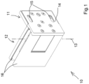
- the hinge designated as a whole with 10, serves as a hinge fitting for a glass door that is attached to a wall (not shown).
- the hinge 10 has a first hinge part 11 and a second hinge part 12, which are connected to one another in an articulated manner about a pivot axis 13. While the first hinge part 11 is provided with a fastening plate 14 with two elongated holes 15 with which it can be screwed to the wall, the second hinge part 12 has two clamping jaws 16, between which the glass door to be held is held clamped, as is known for the door of a shower partition, for example.
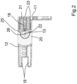
- the hinge 10 is equipped with a locking device, designated overall by 17, which has a locking element 18 assigned to the first hinge part 11, which is accommodated in a housing 20 fastened to the fastening plate 14 with screws 19.
- the locking element 18 is movable in the housing 20 transversely to the pivot axis 13. It is pre-tensioned by two compression springs 21, which engage in spring receptacles 22 in the locking element 18 and press there against the rear of the locking element 18 facing away from the pivot axis. With their ends protruding from the spring receptacles, the springs are supported on the fastening plate 14.
- the latter is provided with two short blind holes 23, which are aligned coaxially with the spring receptacles 22 in the locking element 18 when the housing 20 is mounted and together with them ensure that the compression springs 21 cannot buckle sideways.
- the locking element 18 is provided with two rotatably mounted pressure rollers 25 on its front side 24 directed towards the pivot axis 13.
- the locking body 26 has a central section 27 with two annular shoulders 28, the height of which is adapted to the position of the pressure rollers 25, in each of which a locking recess 29 is provided in the form of a concave recess, into which the pressure rollers 25 on the locking element 18 can engage in order to position the rest position of the door.
- the housing 20 with the locking element 18 slidably received therein is mounted so as to be rotatable about the central section 27 of the locking body 26.
- the locking body 26 has a pivot pin 30 at its upper and lower ends, with which it is secured to the second hinge part 12.
- the second band part 12 is designed to be divided/divisible transversely to the pivot axis 13, i.e. in the exemplary embodiment in a horizontal direction or plane E.
- the second band part 12 thus comprises a first web part 31 with a first band web 32 and a second web part 33 with a second band web 34.
- the two band webs 32 and 34 are designed as ring receptacles 35 closed on the circumference, into which the pivot pins 29 of the closing body 26 fit with very little play.
- the two web parts 31, 33 are detachably connected to one another by means of screw connections.
- the arrangement in the embodiment shown is such that a cylinder head screw 36 can be screwed through a hole provided parallel to the joint axis 13 in one of the two web parts into a matching threaded hole 37 provided on the other web part in order to connect the two web parts to one another.
- form-fitting guides that interact with one another in the manner of a groove 38 and spring 39 are provided, which ensure that the two parts are positioned exactly relative to one another.
- the assembly of the locking body 26 together with the housing 20 mounted thereon and the locking element 18 accommodated therein on the second hinge part 12 can be carried out easily when the web parts 31, 33 are separated from one another by inserting the pivot pins 30 from the inside into the associated, ring-shaped closed band webs 32, 34.
- the two web parts 31, 33 can then be screwed together with the two cylinder head screws 36.
- the locking body 26 is then articulated to the band webs 32, 34 with practically no play and can be adjusted continuously to the desired position by turning about the pivot axis 13, in which the rest position or zero position between the two band parts 11, 12 is reached.
- the locking body 26 is then secured against twisting by means of grub screws 40, which for this purpose pass transversely through the band webs 32, 34 in threaded holes 41 and can be adjusted against the pivot pins 29 of the locking body 26 mounted in the ring holders 35 and clamp it firmly to the band webs.
- the second band part 12 is provided with a securing part 42 which covers the two web parts 31, 33 in the area of their dividing plane E and which, when the web parts 31, 33 are connected to each other, is screwed to them with a total of four countersunk head screws 43, two of these screws 43 being screwed into corresponding threaded holes 44o on the upper of the two web parts 31 and 44u on the lower web part 33.
- the invention makes it particularly easy to adjust the rest position/zero position of the hinge or the door supported by it, without causing inaccuracies/difficulties due to too much play between the hinge webs of the second hinge part and the locking body held by it.
- the desired position can be easily adjusted by simply loosening and then re-tightening the grub screws, which are particularly easy to access from the side.
Landscapes
- Engineering & Computer Science (AREA)
- Mechanical Engineering (AREA)
- Hinges (AREA)
Abstract
Description
- Die Erfindung betrifft ein Gelenkband insbesondere für Glastüren, mit zwei um eine Schwenkachse gelenkig miteinander verbundenen Bandteilen sowie mit einer zwischen den beiden Bandteilen wirksamen Rastvorrichtung, die im Wesentlichen aus mindestens einem dem ersten Bandteil zugeordneten, gegen die Wirkung wenigstens eines Federelements beweglich geführten Riegelelement und einem dem zweiten Bandteil zugeordneten Schließkörper mit mindestens einer mit dem Riegelelement in einer Raststellung zusammenwirkenden Rastausnehmung besteht, wobei der Schließkörper zwischen zwei am zweiten Bandteil ausgebildeten Bandstegen koaxial zur Schwenkachse angeordnet und in verschiedenen Winkelstellungen seiner Rastausnehmung arretierbar ist.
- Derartige Gelenkbänder, die beispielsweise für Möbeltüren oder auch eine Glastür einer Duschabtrennung eingesetzt werden können, sind aus der
DE 10 2005 025 278 B3 und derEP 3 741 944 A1 bekannt. Mit Hilfe der einstellbaren Rastvorrichtung kann die Schließlage der an dem Gelenkband angeschlagenen Tür eingestellt werden, indem der koaxial zur Schwenkachse zwischen den beiden Bandstegen des zweiten Bandteils angeordnete Schließkörper mit seiner Rastausnehmung so eingestellt wird, dass die Tür die gewünschte Winkellage einnimmt, wenn das Riegelelement von dem Federelement in die Rastausnehmung gedrückt wird. - Damit die derart einmal gefundene Schließstellung der Tür bzw. des Scharniers sich nicht ungewollt wieder verändert, ist es notwendig, den Schließkörper in seiner korrekten Winkelstellung am zweiten Bandteil zuverlässig zu arretieren. Dies wird bei dem Stand der Technik dadurch bewirkt, dass die beiden Bandstege am zweiten Bandteil jeweils in einer Ebene parallel zur Schwenkachse geteilt ausgeführt sind und eine fest am zweiten Bandteil ausgebildete erste Klemmbacke und eine an einem lösbaren Spannmittelteil ausgebildete zweite Klemmbacke umfassen, die mittels einer Verschraubung und ggf. einer Rasteinrichtung gegeneinander anstellbar sind. Dabei spannen die Klemmbacken Endabschnitte des Schließkörpers zwischen sich ein und sichern somit dessen Position relativ zum zweiten Bandteil und damit die gewünschte Winkelstellung der Rastausnehmung.
- Probleme bereitet bei den bekannten Gelenkbändern die Montage der einzelnen Bestandteile zum fertigen Gelenkband, insbesondere der Einbau des Schließkörpers und dessen Einstellung in der korrekten Winkellage, denn der Einbau und insbesondere die Einstellung der Schließlage (Nulllage) können nur erfolgen, solange die Klemmbacken durch ausreichendes Öffnen der Verschraubung die dazwischen liegenden Endabschnitte des Schließkörpers so weit freigeben, dass dieser relativ zum zweiten Bandteil in die gewünschte Position eingestellt werden kann. Eine genaue Einstellung ist dabei sehr schwer zu erreichen, insbesondere dann, wenn der Einstellvorgang im montierten Zustand des Gelenkbands mit daran angebrachter Tür erfolgen soll. Das Türgewicht führt nämlich dazu, dass der Schließkörper seine koaxiale Positionierung zur Schwenkachse während des Einstellvorgangs nicht beibehält, sondern bei dem Montage- und/oder Einstellvorgang mit verhältnismäßig großer Kraft quer zur Richtung der Schwenkachse belastet wird, was ein genaues Arbeiten erschwert.
- Aufgabe der Erfindung ist es, diese Nachteile zu vermeiden und die Montage und Einstellung des Gelenkbands zu erleichtern.
- Diese Aufgabe wird mit der Erfindung dadurch gelöst, dass das zweite Bandteil zumindest teilweise quer zur Schwenkachse geteilt/teilbar ausgeführt ist und ein erstes, den einen der beiden Bandstege aufweisendes Stegteil und ein zweites, den anderen der beiden Bandstege aufweisendes Stegteil umfasst, wobei die beiden Stegteile mittels mindestens eines Verbindungselements lösbar miteinander verbindbar/verbunden sind.
- Die Erfindung verlässt somit den im Stand der Technik bekannten Weg mit zweiteilig ausgestalteten, in einer Ebene parallel zur Schwenkachse geteilten Bandstegen. Vielmehr ist bei der Erfindung das zweite Bandteil geteilt ausgeführt, und zwar in einer Ebene, die quer oder rechtwinklig zur Schwenkachse verläuft. Der Schließkörper kann in vorteilhafter Ausgestaltung einen die Rastausnehmung(en) aufweisenden Mittenabschnitt sowie zwei an einander gegenüber liegenden Endseiten des Mittenabschnitts relativ zu diesem drehfest angeordnete und vorzugsweise im Querschnitt reduzierte Gelenkzapfen aufweisen, die im montierten Zustand an den Bandstegen des zweiten Bandteils festgelegt sind. Die Bandstege können durch die erfindungsgemäß vorgeschlagene Teilung des zweiten Bandteils in einer Teilungsrichtung oder -ebene quer zur Schwenkachse vollumfänglich geschlossen gestaltet sein, indem sie beispielsweise umfangsseitig geschlossene Ringaufnahmen bilden, in die die Gelenkzapfen des Schließkörpers einfassen. Die Montage des Schließkörpers ist bei der Erfindung auch mit geschlossen gestalteten Bandstegen problemlos möglich. Zu diesem Zweck nämlich können die beiden zunächst voneinander separierten Stegteile mit den daran ausgebildeten Bandstegen an den beiden Enden des Schließkörper montiert werden, indem sie in Richtung der Schwenkachse an diesen angesteckt werden, so dass die beiden Bandstege die endseitig am Schließkörper ausgebildeten Gelenkzapfen o.dgl. umschließen. Anschließend werden die beiden Stegteile mit Hilfe des dafür vorgesehenen Verbindungselements, das vorzugsweise von mindestens einer zwischen den beiden Stegteilen wirksamen Schraubverbindung gebildet wird, fest miteinander verbunden, wobei diese Verbindung bei der nachfolgenden Justage des Schließkörpers in die gewünschte Winkelstellung nicht gelöst werden muss.
- In vorteilhafter Weiterbildung der Erfindung kann das zweite Bandteil ein die beiden Stegteile im Bereich ihrer Teilungsebene überdeckendes Sicherungsteil umfassen, das im miteinander verbundenen Zustand der Stegteile mit diesen verbunden, vorzugsweise verschraubt ist. Durch die Anordnung des Sicherungsteils wird das zwischen den Stegteilen wirksame Verbindungselement, in der bevorzugten Ausführungsform also die vorgesehene Schraubverbindung, entlastet und sichergestellt, dass sich die Verbindung zwischen den Stegteilen nicht unabsichtlich lösen kann.
- Um die eingestellte, gewünschte Drehposition des an den Bandstegen gelagerten Schließkörpers festzulegen, können verschiedenen Maßnahmen vorgesehen werden. Zum Beispiel kann der Schließkörper in einer bevorzugten Ausführungsform der Erfindung mittels an den Bandstegen vorgesehenen Drehsicherungselementen drehfest arretierbar sein. Bei diesen Drehsicherungselementen kann es sich besonders bevorzugt um Klemmschrauben, z.B. Madenschrauben, handeln, die die Bandstege quer durchsetzen und gegen den daran gelagerten Schließkörper bzw. dessen Gelenkzapfen anstellbar sind.
- Vorteilhaft ist es, wenn die beiden Stegteile mit miteinander zusammenwirkenden Formschlussführungen versehen sind. Damit wird in besonders einfacher Weise sichergestellt, dass bei der Montage des Gelenkbands die beiden Stegteile in genauer Ausrichtung der Bandstege zueinander miteinander verbunden werden, so dass der Schließkörper genau koaxial zur Schwenkachse zwischen den beiden Bandstegen gelagert ist.
- Die Rastvorrichtung kann ein das Riegelelement quer zur Schwenkachse beweglich aufnehmendes Gehäuse aufweisen, das um den Mittenabschnitt des Schließkörpers drehbar gelagert ist. Das Riegelelement kann in vorteilhafter Ausgestaltung der Erfindung an seiner zum Schließkörper gerichteten Vorderseite mit mindestens einer drehbar gelagerten Druckrolle versehen sein, die zur Verrastung mit dem Schließkörper mit der an diesem ausgebildeten Rastausnehmung zusammenwirkt.
- Weitere Merkmale und Vorteile der Erfindung ergeben sich aus der nachfolgenden Beschreibung und der Zeichnung, worin eine bevorzugte Ausführungsform der Erfindung anhand eines Beispiels näher erläutert wird. Es zeigt:
- Fig. 1
- ein Gelenkband nach der Erfindung in einer perspek-tivischen Darstellung;
- Fig. 2
- den Gegenstand der
Fig. 1 im Horizontalschnitt; - Fig. 3
- den Gegenstand der
Fig. 1 und2 in einem Vertikalschnitt durch das zweiten Bandteil; - Fig. 4
- das Gelenkband nach den
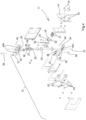
Fig. 1 bis 3 in einer ersten perspektivischen, auseinandergezogenen Darstellung seiner Einzelbauteile (Explosionsansicht) in einer ersten Blickrichtung; und - Fig. 5
- das Gelenkband in einer zweiten Explosionsansicht mit anderer Blickrichtung.
- Das in seiner Gesamtheit mit 10 bezeichnete Gelenkband dient als Scharnierbeschlag für eine Glastüre, die an einer (nicht dargestellten) Wand befestigt ist. Das Gelenkband 10 weist ein erstes Bandteil 11 und ein zweites Bandteil 12 auf, die um eine Schwenkachse 13 gelenkig miteinander verbunden sind. Während das erste Bandteil 11 mit einer Befestigungsplatte 14 mit zwei Langlöchern 15 versehen ist, mit denen es an der Wand festgeschraubt werden kann, weist das zweite Bandteil 12 zwei Klemmbacken 16 auf, zwischen denen die zu haltende Glastür eingespannt gehalten wird, wie dies beispielsweise für die Tür einer Duschabtrennung bekannt ist.
- Das Gelenkband 10 ist mit einer insgesamt mit 17 bezeichneten Rastvorrichtung ausgestattet, die ein dem ersten Bandteil 11 zugeordnetes Riegelelement 18 aufweist, das in einem an der Befestigungsplatte 14 mit Schrauben 19 befestigten Gehäuse 20 aufgenommen ist. Das Riegelelement 18 ist in dem Gehäuse 20 quer zur Schwenkachse 13 beweglich. Es wird von zwei Druckfedern 21 vorgespannt, die in Federaufnahmen 22 im Riegelelement 18 einfassen und dort gegen die der Schwenkachse abgewandte Rückseite des Riegelelements 18 drücken. Mit ihren aus den Federaufnahmen herausragenden Enden stützen sich die Federn an der Befestigungsplatte 14 ab. Diese ist hierfür mit zwei kurzen Sacklöchern 23 versehen, die im montierten Zustand des Gehäuses 20 koaxial zu den Federaufnahmen 22 im Riegelelement 18 ausgerichtet sind und zusammen mit diesen sicherstellen, dass die Druckfedern 21 nicht seitlich ausknicken können.
- Das Riegelelement 18 ist an seiner zur Schwenkachse 13 gerichteten Vorderseite 24 mit zwei drehbar gelagerten Druckrollen 25 versehen.
- Diese wirken mit einem dem zweiten Bandteil 12 zugeordneten Schließkörper 26 zusammen, der als Bestandteil der Rastvorrichtung 17 koaxial zur Schwenkachse 13 an dem zweiten Bandteil 12 montiert ist. Der Schließkörper 26 hat einen Mittenabschnitt 27 mit zwei in ihrer Höhenlage an die Position der Druckrollen 25 angepassten Ringabsätzen 28, in denen jeweils eine Rastausnehmung 29 in Form einer konkaven Einziehung vorgesehen ist, in die die Druckrollen 25 am Riegelelement 18 zur Positionierung der Ruhestellung der Tür einfassen können. Das Gehäuse 20 mit dem darin verschieblich aufgenommenen Riegelelement 18 ist um den Mittenabschnitt 27 des Schließkörpers 26 drehbar gelagert. Der Schließkörper 26 weist an seinem oberen und unteren Ende jeweils einen Gelenkzapfen 30 auf, mit denen er am zweiten Bandteil 12 festgelegt ist. Dabei ist das zweite Bandteil 12 gemäß der Erfindung quer zur Schwenkachse 13, bei dem Ausführungsbeispiel also in einer horizontalen Richtung oder Ebene E geteilt/teilbar ausgeführt. Somit umfasst das zweite Bandteil 12 ein erstes Stegteil 31 mit einem ersten Bandsteg 32 und ein zweites Stegteil 33 mit einem zweiten Bandsteg 34. Die beiden Bandstege 32 und 34 sind als umfangsseitig geschlossene Ringaufnahmen 35 ausgebildet, in die die Gelenkzapfen 29 des Schließkörpers 26 mit sehr geringem Spiel einfassen.
- Wie man insbesondere in den
Fig.4 und5 gut erkennen kann, sind die beiden Stegteile 31, 33 mittels Schraubverbindungen lösbar miteinander verbindbar/verbunden. Die Anordnung ist bei der gezeigten Ausführungsform so, dass je eine Zylinderkopfschraube 36 durch ein parallel zur Gelenkachse 13 vorgesehenes Loch in dem einen der beiden Stegteile in eine dazu passend am anderen Stegteil vorgesehene Gewindebohrung 37 eingeschraubt werden kann, um die beiden Stegteile miteinander zu verbinden. An den Kontaktflächen der beiden Stegteile 31, 33 sind miteinander zusammenwirkende Formschlussführungen nach Art einer Nut 38 und Feder 39 vorgesehen, die eine exakte Positionierung der beiden Teile zueinander gewährleisten. Die Montage des Schließkörpers 26 zusammen mit dem darauf montierten Gehäuse 20 und dem darin aufgenommenen Riegelelement 18 am zweiten Bandteil 12 kann einfach bei voneinander getrennten Stegteilen 31, 33 erfolgen, indem die Gelenkzapfen 30 von innen in die zugehörigen, ringförmig geschlossenen Bandstege 32, 34 eingesteckt werden. Anschließend können die beiden Stegteile 31, 33 mit den beiden Zylinderkopfschrauben 36 miteinander verschraubt werden. Der Schließkörper 26 ist dann praktisch spielfrei an den Bandstegen 32, 34 angelenkt und kann durch Verdrehen um die Schwenkachse 13 stufenlos genau in die gewünschte Stellung eingestellt werden, in der die Ruheposition oder Nulllage zwischen den beiden Bandteilen 11, 12 erreicht ist. In dieser gewünschten Stellung wird der Schließkörper 26 dann mittels Madenschrauben 40 gegen Verdrehen gesichert, die hierzu die Bandstege 32, 34 in Gewindebohrungen 41 quer durchsetzen und gegen die in den Ringaufnahmen 35 gelagerten Gelenkzapfen 29 des Schließkörpers 26 anstellbar sind und diesen fest an den Bandstegen einklemmen. - Zur Sicherung der beiden Stegteile 31, 33 gegeneinander und insbesondere auch zur Entlastung der diese miteinander verschraubenden Schrauben 36 ist das zweite Bandteil 12 mit einem die beiden Stegteile 31, 33 im Bereich ihrer Teilungsebene E überdeckenden Sicherungsteil 42 versehen, das im miteinander verbundenen Zustand der Stegteile 31, 33 mit diesen mit insgesamt vier Senkkopfschrauben 43 verschraubt ist, wobei je zwei dieser Schrauben 43 in zugehörige Gewindebohrungen 44o am oberen der beiden Stegteile 31 und 44u am unteren Stegteil 33 eingeschraubt sind.
- Mit der Erfindung ist es in besonders einfacher Weise möglich, die Ruheposition/Nulllage des Gelenkbands bzw. der von diesem getragenen Tür einzustellen, ohne dass es dabei infolge von zu viel Spiel zwischen den Bandstegen des zweiten Bandteils und dem davon aufgenommenen Schließkörper zu Ungenauigkeiten/Schwierigkeiten kommen. Ein Nachstellen der gewünschten Position ist nach einfachem Lösen und anschließendem Wiederfestziehen der von der Seite besonders leicht zugänglichen Madenschrauben problemlos möglich.
Claims (10)
- Gelenkband insbesondere für Glastüren, mit zwei um eine Schwenkachse (13) gelenkig miteinander verbundenen Bandteilen (11,12) sowie mit einer zwischen den beiden Bandteilen (11,12) wirksamen Rastvorrichtung (17), die im Wesentlichen aus mindestens einem dem ersten Bandteil (11) zugeordneten, gegen die Wirkung wenigstens eines Federelements (21) beweglich geführten Riegelelement (18) und einem dem zweiten Bandteil (12) zugeordneten Schließkörper (26) mit mindestens einer mit dem Riegelelement (18) in einer Raststellung zusammenwirkenden Rastausnehmung (29) besteht, wobei der Schließkörper (26) zwischen zwei am zweiten Bandteil (12) ausgebildeten Bandstegen (32,34) koaxial zur Schwenkachse (13) angeordnet und in verschiedenen Winkelstellungen seiner Rastausnehmung (29) arretierbar ist, dadurch gekennzeichnet, dass das zweite Bandteil (12) zumindest teilweise quer zur Schwenkachse (13) geteilt/teilbar ausgeführt ist und ein erstes, den einen der beiden Bandstege (32) aufweisendes Stegteil (31) und ein zweites, den anderen der beiden Bandstege (34) aufweisendes Stegteil (33) umfasst, wobei die beiden Stegteile (31,33) mittels mindestens eines Verbindungselements (36) lösbar miteinander verbindbar/verbunden sind.
- Gelenkband nach Anspruch 1, dadurch gekennzeichnet, dass der Schließkörper (26) einen die Rastausnehmung(en) (29
)aufweisenden Mittenabschnitt (27) sowie zwei an einander gegenüber liegenden Endseiten des Mittenabschnitts (27) relativ zu diesem drehfest angeordnete und vorzugsweise im Querschnitt reduzierte Gelenkzapfen (30) aufweist, die im montierten Zustand an den Bandstegen (32,34) des zweiten Bandteils (12) festgelegt sind. - Gelenkband nach Anspruch 2, dadurch gekennzeichnet, dass die Bandstege (32,34) umfangsseitig geschlossene Ringaufnahmen (35) bilden, in die die Gelenkzapfen (30) des Schließkörpers (26) einfassen.
- Gelenkband nach einem der Ansprüche 1 bis 3, dadurch gekennzeichnet, dass das Verbindungselement von mindestens einer zwischen den beiden Stegteilen (31,33) wirksamen Schraubverbindung (36,37) gebildet wird.
- Gelenkband nach einem der Ansprüche 1 bis 4, dadurch gekennzeichnet, dass das zweite Bandteil (12) ein die beiden Stegteile (31,33) im Bereich ihrer Teilungsebene (E) überdeckendes Sicherungsteil (42) umfasst, das im miteinander verbundenen Zustand der Stegteile (31,33) mit diesen verbunden, vorzugsweise verschraubt ist.
- Gelenkband nach einem der Ansprüche 1 bis 5, dadurch gekennzeichnet, dass der Schließkörper (26) mittels an den Bandstegen (32,34) vorgesehenen Drehsicherungselementen (40) drehfest arretierbar ist
- Gelenkband nach Anspruch 5, dadurch gekennzeichnet, dass die Drehsicherungselemente Klemmschrauben (40) sind, die die Bandstege (32,34) quer durchsetzen und gegen den daran gelagerten Schließkörper (26) bzw. dessen Gelenkzapfen (30) anstellbar sind.
- Gelenkband nach einem der Ansprüche 1 bis 7, dadurch gekennzeichnet, dass die beiden Stegteile (31,33) mit miteinander zusammenwirkenden Formschlussführungen (38,39) versehen sind.
- Gelenkband nach einem der Ansprüche 1 bis 8, dadurch gekennzeichnet, dass die Rastvorrichtung (17) ein das Riegelelement (18) quer zur Schwenkachse (13) beweglich aufnehmendes Gehäuse (20) aufwiest, das um den Mittenabschnitt (27) des Schließkörpers (26) drehbar gelagert ist.
- Gelenkband nach einem der Ansprüche 1 bis 9, dadurch gekennzeichnet, dass das Riegelelement (18) an seiner zum Schließkörper gerichteten Vorderseite (24) mit mindestens einer drehbar gelagerten Druckrolle (25) versehen ist, die zur Verrastung mit dem Schließkörper (26) mit der an diesem ausgebildeten Rastausnehmung (29) zusammenwirkt.
Applications Claiming Priority (1)
| Application Number | Priority Date | Filing Date | Title |
|---|---|---|---|
| DE202023104548.0U DE202023104548U1 (de) | 2023-08-10 | 2023-08-10 | Gelenkband |
Publications (3)
| Publication Number | Publication Date |
|---|---|
| EP4506526A1 true EP4506526A1 (de) | 2025-02-12 |
| EP4506526B1 EP4506526B1 (de) | 2025-12-24 |
| EP4506526C0 EP4506526C0 (de) | 2025-12-24 |
Family
ID=92264110
Family Applications (1)
| Application Number | Title | Priority Date | Filing Date |
|---|---|---|---|
| EP24193294.6A Active EP4506526B1 (de) | 2023-08-10 | 2024-08-07 | Gelenkband |
Country Status (2)
| Country | Link |
|---|---|
| EP (1) | EP4506526B1 (de) |
| DE (1) | DE202023104548U1 (de) |
Families Citing this family (1)
| Publication number | Priority date | Publication date | Assignee | Title |
|---|---|---|---|---|
| DE202024101297U1 (de) * | 2024-03-15 | 2025-06-23 | Pauli + Sohn Gmbh Metallwaren | Gelenkband |
Citations (3)
| Publication number | Priority date | Publication date | Assignee | Title |
|---|---|---|---|---|
| DE102005025278B3 (de) | 2005-06-02 | 2006-10-12 | Gang Gwo Industrial Co., Ltd., Ta Liao | Einstellbares Scharnier für eine Glastür |
| US20100275410A1 (en) * | 2009-05-01 | 2010-11-04 | Door & Window Hardware Co. | Automatic positioning hinge |
| EP3741944A1 (de) | 2019-05-21 | 2020-11-25 | Bohle AG | Gelenkband |
Family Cites Families (3)
| Publication number | Priority date | Publication date | Assignee | Title |
|---|---|---|---|---|
| DE8703236U1 (de) * | 1987-03-03 | 1987-05-27 | Ed. Scharwächter GmbH + Co KG, 42855 Remscheid | Aushängbares Flügelscharnier |
| DE102008018646B3 (de) * | 2008-04-11 | 2009-11-19 | Pauli + Sohn Gmbh Metallwaren | Gelenkband |
| AT515135B1 (de) * | 2013-11-15 | 2017-05-15 | Blum Gmbh Julius | Scharnier, insbesondere für ein Möbelstück |
-
2023
- 2023-08-10 DE DE202023104548.0U patent/DE202023104548U1/de active Active
-
2024
- 2024-08-07 EP EP24193294.6A patent/EP4506526B1/de active Active
Patent Citations (4)
| Publication number | Priority date | Publication date | Assignee | Title |
|---|---|---|---|---|
| DE102005025278B3 (de) | 2005-06-02 | 2006-10-12 | Gang Gwo Industrial Co., Ltd., Ta Liao | Einstellbares Scharnier für eine Glastür |
| US20100275410A1 (en) * | 2009-05-01 | 2010-11-04 | Door & Window Hardware Co. | Automatic positioning hinge |
| EP3741944A1 (de) | 2019-05-21 | 2020-11-25 | Bohle AG | Gelenkband |
| EP3741944B1 (de) * | 2019-05-21 | 2023-03-29 | Bohle AG | Gelenkband |
Also Published As
| Publication number | Publication date |
|---|---|
| EP4506526B1 (de) | 2025-12-24 |
| DE202023104548U1 (de) | 2024-11-12 |
| EP4506526C0 (de) | 2025-12-24 |
Similar Documents
| Publication | Publication Date | Title |
|---|---|---|
| EP0259618B1 (de) | Während und nach der Montage verstellbares Tür- und Fensterband | |
| DE4219681C2 (de) | Einstellbares Abhebescharnier | |
| EP0699419B1 (de) | Osteosynthetischer Fixateur | |
| WO2016146218A1 (de) | Tür- oder fensterscharnier | |
| EP3613931B1 (de) | Baugruppe eines bandes zur um eine scharnierachse scharnierbeweglichen verbindung eines flügels an einem rahmen | |
| EP2345787B1 (de) | Türband für Aluminiumtüren | |
| EP4506526B1 (de) | Gelenkband | |
| DE3516480C2 (de) | ||
| EP2345786B1 (de) | Türband für Aluminiumtüren | |
| DE102008018646B3 (de) | Gelenkband | |
| DE19642637C2 (de) | Türscharnier zur schwenkbaren Lagerung eines Türflügels an einem Türrahmen | |
| DE3920195A1 (de) | Scharnier | |
| EP2172610B1 (de) | Bandbefestigungsteil | |
| EP2149664B1 (de) | Unterkonstruktion für ein Scharnierband und Scharnierband mit einer solchen Unterkonstruktion zur Befestigung an einem Türblatt | |
| DE102015012641B3 (de) | Gelenkverbindung | |
| DE10105264C1 (de) | Scharnierband für Türen und Fenster | |
| AT500599B1 (de) | Mehrdimensional verstellbares türband | |
| EP2418344B1 (de) | Türflügelbandteil, Türbandvorrichtung sowie Verwendungen derselben | |
| EP2208843B1 (de) | Scharnier für eine Tür | |
| EP1563152B1 (de) | Gelenkband | |
| DE102012104863B3 (de) | Türbandanordnung mit einem Türband und einem Aufnahmeelement | |
| DE4418082C1 (de) | Mehrteiliges Scharnier | |
| EP4632181A1 (de) | Gelenkband | |
| DE102021121976B3 (de) | Türband und Türbandanordnung | |
| EP0671531B1 (de) | Scharnier |
Legal Events
| Date | Code | Title | Description |
|---|---|---|---|
| PUAI | Public reference made under article 153(3) epc to a published international application that has entered the european phase |
Free format text: ORIGINAL CODE: 0009012 |
|
| STAA | Information on the status of an ep patent application or granted ep patent |
Free format text: STATUS: REQUEST FOR EXAMINATION WAS MADE |
|
| 17P | Request for examination filed |
Effective date: 20250109 |
|
| AK | Designated contracting states |
Kind code of ref document: A1 Designated state(s): AL AT BE BG CH CY CZ DE DK EE ES FI FR GB GR HR HU IE IS IT LI LT LU LV MC ME MK MT NL NO PL PT RO RS SE SI SK SM TR |
|
| RIC1 | Information provided on ipc code assigned before grant |
Ipc: E05D 5/02 20060101AFI20250611BHEP Ipc: E05D 11/10 20060101ALI20250611BHEP |
|
| GRAP | Despatch of communication of intention to grant a patent |
Free format text: ORIGINAL CODE: EPIDOSNIGR1 |
|
| STAA | Information on the status of an ep patent application or granted ep patent |
Free format text: STATUS: GRANT OF PATENT IS INTENDED |
|
| INTG | Intention to grant announced |
Effective date: 20250723 |
|
| GRAS | Grant fee paid |
Free format text: ORIGINAL CODE: EPIDOSNIGR3 |
|
| GRAA | (expected) grant |
Free format text: ORIGINAL CODE: 0009210 |
|
| STAA | Information on the status of an ep patent application or granted ep patent |
Free format text: STATUS: THE PATENT HAS BEEN GRANTED |
|
| AK | Designated contracting states |
Kind code of ref document: B1 Designated state(s): AL AT BE BG CH CY CZ DE DK EE ES FI FR GB GR HR HU IE IS IT LI LT LU LV MC ME MK MT NL NO PL PT RO RS SE SI SK SM TR |
|
| REG | Reference to a national code |
Ref country code: CH Ref legal event code: F10 Free format text: ST27 STATUS EVENT CODE: U-0-0-F10-F00 (AS PROVIDED BY THE NATIONAL OFFICE) Effective date: 20251224 Ref country code: GB Ref legal event code: FG4D Free format text: NOT ENGLISH |
|
| REG | Reference to a national code |
Ref country code: DE Ref legal event code: R096 Ref document number: 502024000543 Country of ref document: DE |
|
| U01 | Request for unitary effect filed |
Effective date: 20260105 |
|
| U07 | Unitary effect registered |
Designated state(s): AT BE BG DE DK EE FI FR IT LT LU LV MT NL PT RO SE SI Effective date: 20260113 |
|
| PG25 | Lapsed in a contracting state [announced via postgrant information from national office to epo] |
Ref country code: NO Free format text: LAPSE BECAUSE OF FAILURE TO SUBMIT A TRANSLATION OF THE DESCRIPTION OR TO PAY THE FEE WITHIN THE PRESCRIBED TIME-LIMIT Effective date: 20260324 |
|
| PG25 | Lapsed in a contracting state [announced via postgrant information from national office to epo] |
Ref country code: HR Free format text: LAPSE BECAUSE OF FAILURE TO SUBMIT A TRANSLATION OF THE DESCRIPTION OR TO PAY THE FEE WITHIN THE PRESCRIBED TIME-LIMIT Effective date: 20251224 |
|
| PG25 | Lapsed in a contracting state [announced via postgrant information from national office to epo] |
Ref country code: RS Free format text: LAPSE BECAUSE OF FAILURE TO SUBMIT A TRANSLATION OF THE DESCRIPTION OR TO PAY THE FEE WITHIN THE PRESCRIBED TIME-LIMIT Effective date: 20260324 |
|
| PG25 | Lapsed in a contracting state [announced via postgrant information from national office to epo] |
Ref country code: SM Free format text: LAPSE BECAUSE OF FAILURE TO SUBMIT A TRANSLATION OF THE DESCRIPTION OR TO PAY THE FEE WITHIN THE PRESCRIBED TIME-LIMIT Effective date: 20251224 |
|
| PG25 | Lapsed in a contracting state [announced via postgrant information from national office to epo] |
Ref country code: ES Free format text: LAPSE BECAUSE OF FAILURE TO SUBMIT A TRANSLATION OF THE DESCRIPTION OR TO PAY THE FEE WITHIN THE PRESCRIBED TIME-LIMIT Effective date: 20251224 |
|
| PG25 | Lapsed in a contracting state [announced via postgrant information from national office to epo] |
Ref country code: PL Free format text: LAPSE BECAUSE OF FAILURE TO SUBMIT A TRANSLATION OF THE DESCRIPTION OR TO PAY THE FEE WITHIN THE PRESCRIBED TIME-LIMIT Effective date: 20251224 |
|
| PG25 | Lapsed in a contracting state [announced via postgrant information from national office to epo] |
Ref country code: IS Free format text: LAPSE BECAUSE OF FAILURE TO SUBMIT A TRANSLATION OF THE DESCRIPTION OR TO PAY THE FEE WITHIN THE PRESCRIBED TIME-LIMIT Effective date: 20260424 |
|
| PG25 | Lapsed in a contracting state [announced via postgrant information from national office to epo] |
Ref country code: CZ Free format text: LAPSE BECAUSE OF FAILURE TO SUBMIT A TRANSLATION OF THE DESCRIPTION OR TO PAY THE FEE WITHIN THE PRESCRIBED TIME-LIMIT Effective date: 20251224 |
|
| PG25 | Lapsed in a contracting state [announced via postgrant information from national office to epo] |
Ref country code: SK Free format text: LAPSE BECAUSE OF FAILURE TO SUBMIT A TRANSLATION OF THE DESCRIPTION OR TO PAY THE FEE WITHIN THE PRESCRIBED TIME-LIMIT Effective date: 20251224 |
|
| U20 | Renewal fee for the european patent with unitary effect paid |
Year of fee payment: 3 Effective date: 20260707 |