EP4501583A1 - Verfahren und system zur herstellung eines reifenelements - Google Patents
Verfahren und system zur herstellung eines reifenelements Download PDFInfo
- Publication number
- EP4501583A1 EP4501583A1 EP22935767.8A EP22935767A EP4501583A1 EP 4501583 A1 EP4501583 A1 EP 4501583A1 EP 22935767 A EP22935767 A EP 22935767A EP 4501583 A1 EP4501583 A1 EP 4501583A1
- Authority
- EP
- European Patent Office
- Prior art keywords
- tire member
- longitudinal direction
- image data
- tire
- variation
- Prior art date
- Legal status (The legal status is an assumption and is not a legal conclusion. Google has not performed a legal analysis and makes no representation as to the accuracy of the status listed.)
- Pending
Links
Images


Classifications
-
- B—PERFORMING OPERATIONS; TRANSPORTING
- B29—WORKING OF PLASTICS; WORKING OF SUBSTANCES IN A PLASTIC STATE IN GENERAL
- B29C—SHAPING OR JOINING OF PLASTICS; SHAPING OF MATERIAL IN A PLASTIC STATE, NOT OTHERWISE PROVIDED FOR; AFTER-TREATMENT OF THE SHAPED PRODUCTS, e.g. REPAIRING
- B29C48/00—Extrusion moulding, i.e. expressing the moulding material through a die or nozzle which imparts the desired form; Apparatus therefor
- B29C48/03—Extrusion moulding, i.e. expressing the moulding material through a die or nozzle which imparts the desired form; Apparatus therefor characterised by the shape of the extruded material at extrusion
- B29C48/07—Flat, e.g. panels
-
- B—PERFORMING OPERATIONS; TRANSPORTING
- B29—WORKING OF PLASTICS; WORKING OF SUBSTANCES IN A PLASTIC STATE IN GENERAL
- B29C—SHAPING OR JOINING OF PLASTICS; SHAPING OF MATERIAL IN A PLASTIC STATE, NOT OTHERWISE PROVIDED FOR; AFTER-TREATMENT OF THE SHAPED PRODUCTS, e.g. REPAIRING
- B29C48/00—Extrusion moulding, i.e. expressing the moulding material through a die or nozzle which imparts the desired form; Apparatus therefor
- B29C48/25—Component parts, details or accessories; Auxiliary operations
- B29C48/92—Measuring, controlling or regulating
-
- B—PERFORMING OPERATIONS; TRANSPORTING
- B29—WORKING OF PLASTICS; WORKING OF SUBSTANCES IN A PLASTIC STATE IN GENERAL
- B29C—SHAPING OR JOINING OF PLASTICS; SHAPING OF MATERIAL IN A PLASTIC STATE, NOT OTHERWISE PROVIDED FOR; AFTER-TREATMENT OF THE SHAPED PRODUCTS, e.g. REPAIRING
- B29C48/00—Extrusion moulding, i.e. expressing the moulding material through a die or nozzle which imparts the desired form; Apparatus therefor
- B29C48/001—Combinations of extrusion moulding with other shaping operations
- B29C48/0013—Extrusion moulding in several steps, i.e. components merging outside the die
- B29C48/0014—Extrusion moulding in several steps, i.e. components merging outside the die producing flat articles having components brought in contact outside the extrusion die
-
- B—PERFORMING OPERATIONS; TRANSPORTING
- B29—WORKING OF PLASTICS; WORKING OF SUBSTANCES IN A PLASTIC STATE IN GENERAL
- B29C—SHAPING OR JOINING OF PLASTICS; SHAPING OF MATERIAL IN A PLASTIC STATE, NOT OTHERWISE PROVIDED FOR; AFTER-TREATMENT OF THE SHAPED PRODUCTS, e.g. REPAIRING
- B29C48/00—Extrusion moulding, i.e. expressing the moulding material through a die or nozzle which imparts the desired form; Apparatus therefor
- B29C48/001—Combinations of extrusion moulding with other shaping operations
- B29C48/0021—Combinations of extrusion moulding with other shaping operations combined with joining, lining or laminating
-
- B—PERFORMING OPERATIONS; TRANSPORTING
- B29—WORKING OF PLASTICS; WORKING OF SUBSTANCES IN A PLASTIC STATE IN GENERAL
- B29C—SHAPING OR JOINING OF PLASTICS; SHAPING OF MATERIAL IN A PLASTIC STATE, NOT OTHERWISE PROVIDED FOR; AFTER-TREATMENT OF THE SHAPED PRODUCTS, e.g. REPAIRING
- B29C48/00—Extrusion moulding, i.e. expressing the moulding material through a die or nozzle which imparts the desired form; Apparatus therefor
- B29C48/16—Articles comprising two or more components, e.g. co-extruded layers
- B29C48/18—Articles comprising two or more components, e.g. co-extruded layers the components being layers
- B29C48/19—Articles comprising two or more components, e.g. co-extruded layers the components being layers the layers being joined at their edges
-
- B—PERFORMING OPERATIONS; TRANSPORTING
- B29—WORKING OF PLASTICS; WORKING OF SUBSTANCES IN A PLASTIC STATE IN GENERAL
- B29C—SHAPING OR JOINING OF PLASTICS; SHAPING OF MATERIAL IN A PLASTIC STATE, NOT OTHERWISE PROVIDED FOR; AFTER-TREATMENT OF THE SHAPED PRODUCTS, e.g. REPAIRING
- B29C48/00—Extrusion moulding, i.e. expressing the moulding material through a die or nozzle which imparts the desired form; Apparatus therefor
- B29C48/16—Articles comprising two or more components, e.g. co-extruded layers
- B29C48/18—Articles comprising two or more components, e.g. co-extruded layers the components being layers
- B29C48/21—Articles comprising two or more components, e.g. co-extruded layers the components being layers the layers being joined at their surfaces
-
- B—PERFORMING OPERATIONS; TRANSPORTING
- B29—WORKING OF PLASTICS; WORKING OF SUBSTANCES IN A PLASTIC STATE IN GENERAL
- B29C—SHAPING OR JOINING OF PLASTICS; SHAPING OF MATERIAL IN A PLASTIC STATE, NOT OTHERWISE PROVIDED FOR; AFTER-TREATMENT OF THE SHAPED PRODUCTS, e.g. REPAIRING
- B29C48/00—Extrusion moulding, i.e. expressing the moulding material through a die or nozzle which imparts the desired form; Apparatus therefor
- B29C48/25—Component parts, details or accessories; Auxiliary operations
- B29C48/30—Extrusion nozzles or dies
- B29C48/304—Extrusion nozzles or dies specially adapted for bringing together components, e.g. melts within the die
-
- B—PERFORMING OPERATIONS; TRANSPORTING
- B29—WORKING OF PLASTICS; WORKING OF SUBSTANCES IN A PLASTIC STATE IN GENERAL
- B29C—SHAPING OR JOINING OF PLASTICS; SHAPING OF MATERIAL IN A PLASTIC STATE, NOT OTHERWISE PROVIDED FOR; AFTER-TREATMENT OF THE SHAPED PRODUCTS, e.g. REPAIRING
- B29C48/00—Extrusion moulding, i.e. expressing the moulding material through a die or nozzle which imparts the desired form; Apparatus therefor
- B29C48/25—Component parts, details or accessories; Auxiliary operations
- B29C48/30—Extrusion nozzles or dies
- B29C48/35—Extrusion nozzles or dies with rollers
-
- B—PERFORMING OPERATIONS; TRANSPORTING
- B29—WORKING OF PLASTICS; WORKING OF SUBSTANCES IN A PLASTIC STATE IN GENERAL
- B29C—SHAPING OR JOINING OF PLASTICS; SHAPING OF MATERIAL IN A PLASTIC STATE, NOT OTHERWISE PROVIDED FOR; AFTER-TREATMENT OF THE SHAPED PRODUCTS, e.g. REPAIRING
- B29C48/00—Extrusion moulding, i.e. expressing the moulding material through a die or nozzle which imparts the desired form; Apparatus therefor
- B29C48/25—Component parts, details or accessories; Auxiliary operations
- B29C48/36—Means for plasticising or homogenising the moulding material or forcing it through the nozzle or die
- B29C48/49—Means for plasticising or homogenising the moulding material or forcing it through the nozzle or die using two or more extruders to feed one die or nozzle
-
- B—PERFORMING OPERATIONS; TRANSPORTING
- B29—WORKING OF PLASTICS; WORKING OF SUBSTANCES IN A PLASTIC STATE IN GENERAL
- B29D—PRODUCING PARTICULAR ARTICLES FROM PLASTICS OR FROM SUBSTANCES IN A PLASTIC STATE
- B29D30/00—Producing pneumatic or solid tyres or parts thereof
- B29D30/06—Pneumatic tyres or parts thereof (e.g. produced by casting, moulding, compression moulding, injection moulding, centrifugal casting)
-
- G—PHYSICS
- G01—MEASURING; TESTING
- G01N—INVESTIGATING OR ANALYSING MATERIALS BY DETERMINING THEIR CHEMICAL OR PHYSICAL PROPERTIES
- G01N23/00—Investigating or analysing materials by the use of wave or particle radiation, e.g. X-rays or neutrons, not covered by groups G01N3/00 – G01N17/00, G01N21/00 or G01N22/00
- G01N23/02—Investigating or analysing materials by the use of wave or particle radiation, e.g. X-rays or neutrons, not covered by groups G01N3/00 – G01N17/00, G01N21/00 or G01N22/00 by transmitting the radiation through the material
- G01N23/04—Investigating or analysing materials by the use of wave or particle radiation, e.g. X-rays or neutrons, not covered by groups G01N3/00 – G01N17/00, G01N21/00 or G01N22/00 by transmitting the radiation through the material and forming images of the material
-
- G—PHYSICS
- G01—MEASURING; TESTING
- G01N—INVESTIGATING OR ANALYSING MATERIALS BY DETERMINING THEIR CHEMICAL OR PHYSICAL PROPERTIES
- G01N23/00—Investigating or analysing materials by the use of wave or particle radiation, e.g. X-rays or neutrons, not covered by groups G01N3/00 – G01N17/00, G01N21/00 or G01N22/00
- G01N23/02—Investigating or analysing materials by the use of wave or particle radiation, e.g. X-rays or neutrons, not covered by groups G01N3/00 – G01N17/00, G01N21/00 or G01N22/00 by transmitting the radiation through the material
- G01N23/06—Investigating or analysing materials by the use of wave or particle radiation, e.g. X-rays or neutrons, not covered by groups G01N3/00 – G01N17/00, G01N21/00 or G01N22/00 by transmitting the radiation through the material and measuring the absorption
- G01N23/18—Investigating the presence of flaws defects or foreign matter
- G01N23/185—Investigating the presence of flaws defects or foreign matter in tyres
-
- B—PERFORMING OPERATIONS; TRANSPORTING
- B29—WORKING OF PLASTICS; WORKING OF SUBSTANCES IN A PLASTIC STATE IN GENERAL
- B29C—SHAPING OR JOINING OF PLASTICS; SHAPING OF MATERIAL IN A PLASTIC STATE, NOT OTHERWISE PROVIDED FOR; AFTER-TREATMENT OF THE SHAPED PRODUCTS, e.g. REPAIRING
- B29C37/00—Component parts, details, accessories or auxiliary operations, not covered by group B29C33/00 or B29C35/00
- B29C2037/90—Measuring, controlling or regulating
- B29C2037/906—Measuring, controlling or regulating using visualisation means or linked accessories, e.g. screens, printers
-
- B—PERFORMING OPERATIONS; TRANSPORTING
- B29—WORKING OF PLASTICS; WORKING OF SUBSTANCES IN A PLASTIC STATE IN GENERAL
- B29C—SHAPING OR JOINING OF PLASTICS; SHAPING OF MATERIAL IN A PLASTIC STATE, NOT OTHERWISE PROVIDED FOR; AFTER-TREATMENT OF THE SHAPED PRODUCTS, e.g. REPAIRING
- B29C2948/00—Indexing scheme relating to extrusion moulding
- B29C2948/92—Measuring, controlling or regulating
- B29C2948/92009—Measured parameter
- B29C2948/92114—Dimensions
-
- B—PERFORMING OPERATIONS; TRANSPORTING
- B29—WORKING OF PLASTICS; WORKING OF SUBSTANCES IN A PLASTIC STATE IN GENERAL
- B29C—SHAPING OR JOINING OF PLASTICS; SHAPING OF MATERIAL IN A PLASTIC STATE, NOT OTHERWISE PROVIDED FOR; AFTER-TREATMENT OF THE SHAPED PRODUCTS, e.g. REPAIRING
- B29C2948/00—Indexing scheme relating to extrusion moulding
- B29C2948/92—Measuring, controlling or regulating
- B29C2948/92009—Measured parameter
- B29C2948/92247—Optical properties
-
- B—PERFORMING OPERATIONS; TRANSPORTING
- B29—WORKING OF PLASTICS; WORKING OF SUBSTANCES IN A PLASTIC STATE IN GENERAL
- B29C—SHAPING OR JOINING OF PLASTICS; SHAPING OF MATERIAL IN A PLASTIC STATE, NOT OTHERWISE PROVIDED FOR; AFTER-TREATMENT OF THE SHAPED PRODUCTS, e.g. REPAIRING
- B29C2948/00—Indexing scheme relating to extrusion moulding
- B29C2948/92—Measuring, controlling or regulating
- B29C2948/92009—Measured parameter
- B29C2948/92285—Surface properties
-
- B—PERFORMING OPERATIONS; TRANSPORTING
- B29—WORKING OF PLASTICS; WORKING OF SUBSTANCES IN A PLASTIC STATE IN GENERAL
- B29C—SHAPING OR JOINING OF PLASTICS; SHAPING OF MATERIAL IN A PLASTIC STATE, NOT OTHERWISE PROVIDED FOR; AFTER-TREATMENT OF THE SHAPED PRODUCTS, e.g. REPAIRING
- B29C2948/00—Indexing scheme relating to extrusion moulding
- B29C2948/92—Measuring, controlling or regulating
- B29C2948/92009—Measured parameter
- B29C2948/92295—Errors or malfunctioning, e.g. for quality control
-
- B—PERFORMING OPERATIONS; TRANSPORTING
- B29—WORKING OF PLASTICS; WORKING OF SUBSTANCES IN A PLASTIC STATE IN GENERAL
- B29C—SHAPING OR JOINING OF PLASTICS; SHAPING OF MATERIAL IN A PLASTIC STATE, NOT OTHERWISE PROVIDED FOR; AFTER-TREATMENT OF THE SHAPED PRODUCTS, e.g. REPAIRING
- B29C2948/00—Indexing scheme relating to extrusion moulding
- B29C2948/92—Measuring, controlling or regulating
- B29C2948/92323—Location or phase of measurement
- B29C2948/92438—Conveying, transporting or storage of articles
-
- B—PERFORMING OPERATIONS; TRANSPORTING
- B29—WORKING OF PLASTICS; WORKING OF SUBSTANCES IN A PLASTIC STATE IN GENERAL
- B29C—SHAPING OR JOINING OF PLASTICS; SHAPING OF MATERIAL IN A PLASTIC STATE, NOT OTHERWISE PROVIDED FOR; AFTER-TREATMENT OF THE SHAPED PRODUCTS, e.g. REPAIRING
- B29C2948/00—Indexing scheme relating to extrusion moulding
- B29C2948/92—Measuring, controlling or regulating
- B29C2948/92504—Controlled parameter
- B29C2948/9258—Velocity
- B29C2948/9259—Angular velocity
-
- B—PERFORMING OPERATIONS; TRANSPORTING
- B29—WORKING OF PLASTICS; WORKING OF SUBSTANCES IN A PLASTIC STATE IN GENERAL
- B29C—SHAPING OR JOINING OF PLASTICS; SHAPING OF MATERIAL IN A PLASTIC STATE, NOT OTHERWISE PROVIDED FOR; AFTER-TREATMENT OF THE SHAPED PRODUCTS, e.g. REPAIRING
- B29C2948/00—Indexing scheme relating to extrusion moulding
- B29C2948/92—Measuring, controlling or regulating
- B29C2948/92504—Controlled parameter
- B29C2948/9258—Velocity
- B29C2948/926—Flow or feed rate
-
- B—PERFORMING OPERATIONS; TRANSPORTING
- B29—WORKING OF PLASTICS; WORKING OF SUBSTANCES IN A PLASTIC STATE IN GENERAL
- B29C—SHAPING OR JOINING OF PLASTICS; SHAPING OF MATERIAL IN A PLASTIC STATE, NOT OTHERWISE PROVIDED FOR; AFTER-TREATMENT OF THE SHAPED PRODUCTS, e.g. REPAIRING
- B29C2948/00—Indexing scheme relating to extrusion moulding
- B29C2948/92—Measuring, controlling or regulating
- B29C2948/92819—Location or phase of control
- B29C2948/92857—Extrusion unit
- B29C2948/92876—Feeding, melting, plasticising or pumping zones, e.g. the melt itself
- B29C2948/92885—Screw or gear
-
- B—PERFORMING OPERATIONS; TRANSPORTING
- B29—WORKING OF PLASTICS; WORKING OF SUBSTANCES IN A PLASTIC STATE IN GENERAL
- B29C—SHAPING OR JOINING OF PLASTICS; SHAPING OF MATERIAL IN A PLASTIC STATE, NOT OTHERWISE PROVIDED FOR; AFTER-TREATMENT OF THE SHAPED PRODUCTS, e.g. REPAIRING
- B29C48/00—Extrusion moulding, i.e. expressing the moulding material through a die or nozzle which imparts the desired form; Apparatus therefor
- B29C48/25—Component parts, details or accessories; Auxiliary operations
- B29C48/36—Means for plasticising or homogenising the moulding material or forcing it through the nozzle or die
- B29C48/395—Means for plasticising or homogenising the moulding material or forcing it through the nozzle or die using screws surrounded by a cooperating barrel, e.g. single screw extruders
-
- B—PERFORMING OPERATIONS; TRANSPORTING
- B29—WORKING OF PLASTICS; WORKING OF SUBSTANCES IN A PLASTIC STATE IN GENERAL
- B29K—INDEXING SCHEME ASSOCIATED WITH SUBCLASSES B29B, B29C OR B29D, RELATING TO MOULDING MATERIALS OR TO MATERIALS FOR MOULDS, REINFORCEMENTS, FILLERS OR PREFORMED PARTS, e.g. INSERTS
- B29K2021/00—Use of unspecified rubbers as moulding material
-
- B—PERFORMING OPERATIONS; TRANSPORTING
- B29—WORKING OF PLASTICS; WORKING OF SUBSTANCES IN A PLASTIC STATE IN GENERAL
- B29K—INDEXING SCHEME ASSOCIATED WITH SUBCLASSES B29B, B29C OR B29D, RELATING TO MOULDING MATERIALS OR TO MATERIALS FOR MOULDS, REINFORCEMENTS, FILLERS OR PREFORMED PARTS, e.g. INSERTS
- B29K2507/00—Use of elements other than metals as filler
- B29K2507/04—Carbon
-
- B—PERFORMING OPERATIONS; TRANSPORTING
- B29—WORKING OF PLASTICS; WORKING OF SUBSTANCES IN A PLASTIC STATE IN GENERAL
- B29L—INDEXING SCHEME ASSOCIATED WITH SUBCLASS B29C, RELATING TO PARTICULAR ARTICLES
- B29L2030/00—Pneumatic or solid tyres or parts thereof
-
- B—PERFORMING OPERATIONS; TRANSPORTING
- B29—WORKING OF PLASTICS; WORKING OF SUBSTANCES IN A PLASTIC STATE IN GENERAL
- B29L—INDEXING SCHEME ASSOCIATED WITH SUBCLASS B29C, RELATING TO PARTICULAR ARTICLES
- B29L2030/00—Pneumatic or solid tyres or parts thereof
- B29L2030/002—Treads
-
- G—PHYSICS
- G01—MEASURING; TESTING
- G01N—INVESTIGATING OR ANALYSING MATERIALS BY DETERMINING THEIR CHEMICAL OR PHYSICAL PROPERTIES
- G01N2223/00—Investigating materials by wave or particle radiation
- G01N2223/60—Specific applications or type of materials
- G01N2223/645—Specific applications or type of materials quality control
Definitions
- the present invention relates to a method and a system for manufacturing a tire member and particularly to a method and a system for manufacturing a tire member that can reduce variation in predetermined quality in a longitudinal direction of an elongated tire member formed by bonding a plurality of types of constituent members and productively manufacture the tire member.
- Tires are manufactured by using various elongated tire members. Some of these tire members are formed by bonding a plurality of types of constituent members such as different types (compositions) of rubber and reinforcing materials. In a tire manufacturing line, various inspections are performed to grasp quality of these tire members.
- buffer means a festoon mechanism
- a transfer system such as a belt conveyor configured to convey the tire members
- a CT scanner is disposed on the downstream side of the buffer means.
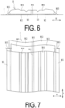
- the elongated tire member R formed by bonding the plurality of types of constituent members M (M1 to M5) as illustrated in FIGS. 6 and 7 is manufactured.
- the tire member R is a tread rubber in which the plurality of types of constituent members M1 to M5 made of unvulcanized rubber respectively extruded by a plurality of extruders 8 (8a to 8e) are bonded.
- the tire member R to be manufactured is not limited to the tread rubber but may be a variety of known members mainly made of rubber such as side rubber and used for manufacturing a tire.
- the constituent members M1 to M5 are different types of unvulcanized rubber, which corresponds to, for example, a case where different compounding agents are blended into the same type of raw rubber, a case where the same compounding agents are blended into the same type of raw rubber in different blend amounts, a case where different compounding agents are blended into different types of raw rubber, and a case where the same compounding agents are blended into different types of raw rubber in different blended amounts.
- each of the constituent members M1 to M5 extends substantially over the entire length in a longitudinal direction L in the cross-sectional shape illustrated in FIG. 6 .
- boundaries between the constituent members M are indicated by dashed lines.
- the constituent member M1 is an earth tread rubber containing a large amount of carbon black and no silica.
- the constituent member M1 is a member having a substantially rectangular cross-section, having the largest thickness among the constituent members M, and having the highest content rate (weight ratio) of carbon black and the smallest specific gravity (density) among the constituent members M.
- the dimension in the width direction of the constituent member M1 is, for example, 0.5 mm or more and 50 mm or less.
- the constituent member M2 is an adhesive rubber containing carbon black, no silica, or a small amount of silica, and is the thinnest sheet-shaped member among the constituent members M.
- the constituent member M3 is an undertread rubber containing carbon black and containing no silica or a small amount of silica, and is a sheet-shaped member thicker than the constituent member M2.
- the constituent member M4 is a cap rubber containing a large amount of silica instead of carbon black and containing no carbon black or a small amount of carbon black.
- the constituent member M4 is the second thickest member after the constituent member M1 among the constituent members M, and has recessed and protruded portions extending in the longitudinal direction L on the surface thereof and different thicknesses depending on positions in the width direction.
- the constituent member M5 is an end rubber containing carbon black and no silica.
- the constituent member M5 forms an inclined surface of an end surface in the width direction of the tire member R, and has different thicknesses depending on positions in the width direction.
- the constituent members M1 to M5 have different specific gravities (densities), and the respective specific gravities (mean values) are grasped in advance.
- the constituent member M4 in which the largest amount of silica is remarkably blended has a large specific gravity compared to the other constituent members M1, M2, M3, and M5.
- Each of the constituent members M may contain other known components depending on the required performance. Containing no component as described above means not only a case where the component is not contained at all but also a case where a very small amount of the component is contained.
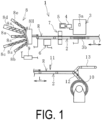
- the manufacturing system 1 includes the plurality of extruders 8 (8a to 8e), the conveying device 2, an X-ray inspection device 3, a calculation device 4, and a control device 9.
- the manufacturing system 1 further includes a terahertz wave measuring device 6, a profile sensor 7, a winding machine 10, a cutting machine 11, a sorting conveyor 12, and a discharge conveyor 13; however, these devices can be optionally provided.
- a monitor 5 is communicably connected to the calculation device 4.
- the extruder 8 is disposed on the upstream side of the conveying device 2 in the conveying direction, and the winding machine 10 and the discharge conveyor 13 are arranged side by side via the sorting conveyor 12 on the downstream side in the conveying direction.
- the terahertz wave measuring device 6, the profile sensor 7, and the X-ray inspection device 3 are arranged in this order from the upstream side to the downstream side in the conveying direction, the arrangement is not limited thereto and can be changed as appropriate.
- the cutting machine 11 is disposed above the conveying device 2.
- the conveying device 2 conveys the tire member R in the longitudinal direction L.
- Various known specifications such as a belt conveyor device and a roller conveyor device in which a large number of rotary rollers are arranged can be adopted as the conveying device 2.
- the X-ray inspection device 3 includes an irradiation unit 3a and a light receiving unit 3b.
- the irradiation unit 3a is disposed above the tire member R placed on the conveying device 2, and the light receiving unit 3b is disposed below the tire member R.
- the tire member R being conveyed by the conveying device 2 passes between the irradiation unit 3a and the light receiving unit 3b in the vertical direction.
- the image data D acquired by the X-ray inspection device 3 and data (image data and the like) on which computational processing is performed by the calculation device 4 are displayed on the monitor 5.
- Various known specifications may be employed as the monitor 5.
- the terahertz wave measuring device 6 includes a transmitter 6a configured to transmit electromagnetic waves (radio waves) at terahertz frequencies (substantially 0.1 THz to 10 THz), and a detector 6b configured to detect reflected waves entering the tire member R and reflected thereon.
- the transmitter 6a and the detector 6b are disposed on the back surface side (lower side in the drawing) of the tire member R placed on the conveying device 2.
- the electromagnetic waves transmitted from the transmitter 6a pass into the tire member R to be reflected at the boundary between the constituent members M.
- the reflected waves reflected at the boundary are detected by the detector 6b.
- the terahertz wave measuring device 6 calculates the cross-sectional area (cross-sectional shape) of at least one type of the constituent member M unevenly distributed on the back surface side of the tire member R based on the angle of reflection (angle of bend at the boundary) of the reflected waves and the time from transmission to detection of the electromagnetic waves.
- the boundary between the constituent members M is greatly changed (the degree of recess/protrusion is large), the reflected waves are diffused, and thus the cross-sectional area (cross-sectional shape) of the constituent member M cannot be accurately calculated.
- the cross-sectional areas (cross-sectional shapes) of the flat sheet-shaped constituent members M2 and M3 are calculated by the terahertz wave measuring device 6.
- a device having known specifications can be employed as the terahertz wave measuring device 6.
- the profile sensor 7 includes an irradiation unit 7a configured to apply a laser beam and a light receiving unit 7b configured to receive reflected light reflected on the outer surface of the tire member R.
- a set of the irradiation unit 7a and the light receiving unit 7b is disposed on each of the top surface side (upper side in the drawing) and the back surface side (lower side in the drawing) of the tire member R placed on the conveying device 2.
- the laser beam emitted from each of the irradiation units 7a is reflected on the outer surface (outer shell surface) of the tire member R.
- the reflected light is received by the light receiving unit 7b forming a set with the irradiation unit.
- the profile sensor 7 calculates the cross-sectional area (cross-sectional shape) of the tire member R based on the angle of reflection of the reflected light and the time from irradiation to reception of the laser beam.
- a sensor having known specifications can be employed as the profile sensor 7.
- the extruder 8 (8a to 8e) includes a cylinder in which a rotationally driven screw 8s is disposed.
- the extruder 8 rotates the screw 8s to feed unvulcanized rubber in which raw rubber and various compounding agents are kneaded to an appropriate viscosity and extrudes the unvulcanized rubber from an extruding head 8H.
- the extruder 8 having various known specifications can be employed.
- the tire member R is formed of five types of bonded constituent members M1 to M5, five of the extruders 8a to 8e are used.
- the control device 9 controls the rotation of the screw 8s of each extruder 8.
- the control device 9 is communicably connected to the calculation device 4, and a variety of data is input from the calculation device 4 to the control device 9.
- the control device 9 controls the rotation speed of the screw 8s of each extruder 8 based on the variety of input data.
- a known computer can be used as the control device 9.
- the winding machine 10 winds and temporarily stocks the tire member R conveyed by the conveying device 2.
- the winding machine 10 includes a take-up drum configured to wind the tire member R together with a liner. In an extrusion molding direct line or the like in which the manufactured tire member R is used immediately in the next step, the winding machine 10 is not necessary.
- the cutting machine 11 cuts across the tire member R placed on the conveying device 2.
- a known cutter such as a rotary round blade is employed as the cutting machine 11.
- the sorting conveyor 12 pivots upward and downward about one end portion (an upstream end portion in the conveying direction).
- the tire member R conveyed by the conveying device 2 is guided to the winding machine 10 when the other end portion of the sorting conveyor 12 pivots downward, and is guided to the discharge conveyor 13 when the other end portion of the sorting conveyor 12 pivots upward.
- the tire member R extruded from the extruder 8 through the extruding head 8H is placed on the conveying device 2 disposed on the front side and is conveyed in the longitudinal direction L.
- the quality inspection of the tire member R is performed by using the terahertz wave measuring device 6 and the profile sensor 7 while conveying the tire member R in the longitudinal direction L.
- the terahertz wave measuring device 6 continuously transmits an electromagnetic wave having a terahertz frequency toward the tire member R by the transmitter 6a from the back surface side of the tire member R being conveyed in the longitudinal direction L.
- the reflected wave entering the tire member R and reflected thereon is detected by the detector 6b.
- the terahertz wave measuring device 6 grasps the cross-sectional shapes (cross-sectional areas) of the constituent members M2 and M3.
- the distribution in the longitudinal direction L of the cross-sectional areas of the constituent members M2 and M3 is grasped. Since the specific gravity of each of the constituent members M2 and M3 is known, the distribution in the longitudinal direction L of the masses of the constituent members M2 and M3 is also grasped.
- the laser beam is continuously applied by the irradiation unit 7a to the tire member R being conveyed in the longitudinal direction L.
- the laser beam reflected on the outer surface of the tire member R is received by the light receiving unit 7b. Accordingly, the profile sensor 7 grasps the cross-sectional shape (cross-sectional area) of the tire member R. Consequently, as illustrated in FIG. 8 , the distribution in the longitudinal direction L of the cross-sectional area of the tire member R is grasped.
- the irradiation unit 3a applies X-rays to the predetermined length range C from the top surface side of the tire member R being conveyed.
- the X-rays transmitted through the predetermined length range C of the tire member R are sequentially received by the light receiving unit 3b.
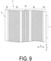
- the image data D illustrated in FIG. 9 based on the X-ray transmittance of the predetermined length range C is acquired by the X-ray inspection device 3. Continuously performing a process of acquiring the image data D as just described allows the image data D of the predetermined length range C continuous without gaps in the longitudinal direction L to be acquired. Each piece of the acquired image data D is sequentially input to the calculation device 4, subjected to computational processing, and analyzed.
- the calculation device 4 calculates, based on the contrast in the image data D, the magnitude of variation (degree of variation) in the dimension in the width direction of the constituent member M1 in the longitudinal direction L. The calculation process by the calculation device 4 will be described in detail below.
- the X-rays applied from the irradiation unit 3a pass through the tire member R and are received by the light receiving unit 3b.
- the attenuation of the X-rays in the tire member R increases more (the amount of absorption increases), and thus the amount of X-rays received by the light receiving unit 3b (the amount of transmitted X-rays) decreases.
- the content of components that easily attenuate X-rays (having high atomic numbers and densities) in the tire member R is high, the amount of X-rays received by the light receiving unit 3b (the amount of transmitted X-rays) decreases. Accordingly, the acquired image data D becomes closer to black and becomes darker.
- the attenuation of the X-rays in the tire member R decreases more (the amount of absorption decreases), and thus the amount of X-rays received by the light receiving unit 3b (the amount of transmitted X-rays) increases.
- the amount of X-rays received by the light receiving unit 3b increases. Accordingly, the acquired image data D becomes closer to white and becomes lighter.
- Silica is a component that significantly attenuates (absorbs) X-rays as compared with carbon black. Consequently, the image data D of the constituent member M containing silica or having a large content of silica is closer to black and darker than that of the constituent member M containing carbon black instead of silica or having a large content of carbon black. As described above, the contrast in the image data D depends on the thickness and the contained component of the tire member R at the position through which the X-rays pass.
- a transit doze Z of X-rays of the tire member R changes in a width direction W.
- the transit dose Z indicates the amount of X-rays received on the back surface side when the X-rays are applied from the front surface side of the tire member R.
- the transit doze Z can be calculated based on the thickness, specific gravity, and attenuation coefficient of the tire member R at the position through which the X-rays pass. The larger the transit doze Z is at the position in the width direction, the darker the color of the image data D is.
- the color is darkest at the thickest position of the constituent member M4, and the color is lightest at the thinnest position. Since the constituent member M1 is the thickest member but has the smallest specific gravity, the color of the image data D is lighter at the position where the constituent member M1 is disposed. At the position where the constituent member M5 is disposed, the color of the image data D becomes lighter toward the end of the tire member R in the width direction.
- the arrangement pitch of diagonal lines is changed in accordance with the color density, and the arrangement pitch of diagonal lines is reduced and densely illustrated in a portion, the color of which is relatively dark.
- the image data D of FIG. 9 there are dark portions and light portions, and the light portions are present at a plurality of positions (the thinnest position of the constituent member M4, the position of the constituent member M1, and the position of the constituent member M5).
- the change of the transit doze Z gradually changes in the same manner as the change of the thickness, and thus the contrast in the image data D gently changes.
- the transit doze Z largely changes due to the difference in the contained components, and thus the contrast in the image data D rapidly changes.
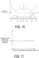
- the transit doze Z in the width direction W of the tire member R illustrated in FIG. 10 is grasped in advance, and the magnitude of the difference in the transit doze Z is used. That is, the transit doze Z of each constituent member M is grasped in advance, and as illustrated in FIG. 9 , a reference range of the magnitude of the difference between the transit dozes Z of the constituent members M at the boundary between the constituent members M adjacent to each other in the width direction W is set. In other words, if the change in the transit doze Z in the width direction W is within the reference range, the reference range is set so as to substantially ensure that the constituent members M1 and M4 are adjacent to each other in the width direction W.
- the range of the difference in contrast of the image data D corresponding to the set reference range is stored in the calculation device 4 as a determination reference.
- the calculation device 4 calculates the magnitude of the difference in contrast in the width direction W with respect to each piece of the image data D.
- the calculation device 4 determines that the detected position in the width direction is the boundary between the constituent members M1 and M4.
- the boundary between the constituent members M1 and M4 is detected at two locations spaced apart from each other in the width direction W. The distance between the boundaries in the width direction W is calculated as the dimension in the width direction of the constituent member M1.
- the magnitude of variation in the dimension in the width direction of the constituent member M1 of the tire member R in the longitudinal direction L is calculated.
- Mc on the vertical axis of FIG. 11 indicates a design value of the dimension in the width direction of the constituent member M1, and it can be grasped how much the dimension in the width direction of the constituent member M1 varies in the longitudinal direction L in the manufactured tire member R.
- the dimension in the width direction is 0 in FIG. 11 , it means that the constituent member M1 is interrupted in the middle of the longitudinal direction L.
- the continuity of the constituent member M1 in the longitudinal direction L can be grasped.
- the X-rays are applied by the irradiation unit 3a to the predetermined length range C of the tire member R so as to cover the entire width of the tire member R; however, the position in the width direction at which the constituent member M1 is disposed in the tire member R is grasped in advance. Consequently, the range in the width direction in which the X-rays are applied can be set to a narrower range including a position previously grasped as the position in the width direction at which the constituent member M1 is disposed.
Landscapes
- Engineering & Computer Science (AREA)
- Mechanical Engineering (AREA)
- Manufacturing & Machinery (AREA)
- Analytical Chemistry (AREA)
- Physics & Mathematics (AREA)
- Biochemistry (AREA)
- General Health & Medical Sciences (AREA)
- General Physics & Mathematics (AREA)
- Immunology (AREA)
- Pathology (AREA)
- Chemical & Material Sciences (AREA)
- Life Sciences & Earth Sciences (AREA)
- Health & Medical Sciences (AREA)
- Tyre Moulding (AREA)
- Extrusion Moulding Of Plastics Or The Like (AREA)
- Analysing Materials By The Use Of Radiation (AREA)
Applications Claiming Priority (2)
| Application Number | Priority Date | Filing Date | Title |
|---|---|---|---|
| JP2022059708A JP7406134B2 (ja) | 2022-03-31 | 2022-03-31 | タイヤ部材の製造方法およびシステム |
| PCT/JP2022/047663 WO2023188641A1 (ja) | 2022-03-31 | 2022-12-23 | タイヤ部材の製造方法およびシステム |
Publications (2)
| Publication Number | Publication Date |
|---|---|
| EP4501583A1 true EP4501583A1 (de) | 2025-02-05 |
| EP4501583A4 EP4501583A4 (de) | 2025-08-27 |
Family
ID=88200089
Family Applications (1)
| Application Number | Title | Priority Date | Filing Date |
|---|---|---|---|
| EP22935767.8A Pending EP4501583A4 (de) | 2022-03-31 | 2022-12-23 | Verfahren und system zur herstellung eines reifenelements |
Country Status (6)
| Country | Link |
|---|---|
| US (1) | US20250108548A1 (de) |
| EP (1) | EP4501583A4 (de) |
| JP (1) | JP7406134B2 (de) |
| KR (1) | KR102841142B1 (de) |
| CN (1) | CN118613364B (de) |
| WO (1) | WO2023188641A1 (de) |
Family Cites Families (18)
| Publication number | Priority date | Publication date | Assignee | Title |
|---|---|---|---|---|
| DE3434904C1 (de) * | 1984-09-22 | 1985-10-17 | Hermann Berstorff Maschinenbau Gmbh, 3000 Hannover | Verfahren und Anlage zum UEberwachen der Abmessungen eines aus einer oder mehreren Mischungen bestehenden,kontinuierlich extrudierten Profilbandes aus Kautschuk oder thermoplastischem Kunststoff |
| US5128077A (en) * | 1991-02-12 | 1992-07-07 | General Tire, Inc. | Method for producing multicomponent extrusions having controlled component contributions |
| JPH07294458A (ja) * | 1994-04-25 | 1995-11-10 | Ishikawajima Harima Heavy Ind Co Ltd | ゴムシートの含有硫黄測定装置 |
| JPH0886635A (ja) * | 1994-09-14 | 1996-04-02 | Bridgestone Corp | タイヤ用帯状未加硫複合部材の断面図形測定装置 |
| US6294119B1 (en) * | 1997-12-26 | 2001-09-25 | Bridgestone Corporation | Production of unvulcanized tread rubber for pneumatic tires |
| JP4684063B2 (ja) * | 2005-09-22 | 2011-05-18 | 株式会社ブリヂストン | タイヤx線撮影装置およびタイヤのx線撮影方法 |
| JP2010217119A (ja) * | 2009-03-18 | 2010-09-30 | Ishida Co Ltd | X線検査装置 |
| US9227372B2 (en) * | 2011-12-19 | 2016-01-05 | The Goodyear Tire & Rubber Company | Conicity correction for rubber component extrusion |
| KR101343922B1 (ko) | 2012-09-06 | 2013-12-24 | 한국타이어 주식회사 | 압출물 측정방법 |
| DE102013104182A1 (de) * | 2013-04-25 | 2014-10-30 | Continental Reifen Deutschland Gmbh | Verfahren zur Identifizierung eines Wechsels von Gummimischungen bei der Herstellung von Reifenbauteilen mit einem Extruder |
| KR101387448B1 (ko) | 2013-05-06 | 2014-04-21 | 한국타이어 주식회사 | 타이어 압출물의 내부저항 측정장치 |
| WO2016199037A1 (en) * | 2015-06-12 | 2016-12-15 | Pirelli Tyre S.P.A. | Method and apparatus for controlling the extrusion of a semifinished product in a tyre building process |
| JP6328723B2 (ja) | 2015-10-27 | 2018-05-23 | 住友ゴム工業株式会社 | 空気入りタイヤおよび架橋ゴム組成物 |
| KR20170108237A (ko) * | 2016-03-17 | 2017-09-27 | 한국타이어 주식회사 | 타이어 압출물의 분리장치 |
| JP2018094930A (ja) | 2016-12-07 | 2018-06-21 | 東洋ゴム工業株式会社 | タイヤの設計方法 |
| KR102508528B1 (ko) * | 2017-09-12 | 2023-03-09 | 삼성전자주식회사 | 측정 장치 및 이를 포함하는 반도체 패키지 제조 시스템 |
| KR102115369B1 (ko) * | 2018-10-16 | 2020-05-27 | 주식회사 성안테크 | 타이어 트레드 결함 검출장치 |
| US20230042121A1 (en) * | 2020-01-20 | 2023-02-09 | Yupo Corporation | Method and system for manufacturing formed product |
-
2022
- 2022-03-31 JP JP2022059708A patent/JP7406134B2/ja active Active
- 2022-12-23 EP EP22935767.8A patent/EP4501583A4/de active Pending
- 2022-12-23 WO PCT/JP2022/047663 patent/WO2023188641A1/ja not_active Ceased
- 2022-12-23 KR KR1020247013185A patent/KR102841142B1/ko active Active
- 2022-12-23 CN CN202280089790.8A patent/CN118613364B/zh active Active
- 2022-12-23 US US18/850,925 patent/US20250108548A1/en active Pending
Also Published As
| Publication number | Publication date |
|---|---|
| KR102841142B1 (ko) | 2025-08-04 |
| CN118613364A (zh) | 2024-09-06 |
| US20250108548A1 (en) | 2025-04-03 |
| EP4501583A4 (de) | 2025-08-27 |
| CN118613364B (zh) | 2025-09-02 |
| WO2023188641A1 (ja) | 2023-10-05 |
| JP7406134B2 (ja) | 2023-12-27 |
| JP2023150551A (ja) | 2023-10-16 |
| KR20240057446A (ko) | 2024-05-02 |
Similar Documents
| Publication | Publication Date | Title |
|---|---|---|
| US7980760B2 (en) | X-ray inspection apparatus and X-ray inspection program | |
| US7991110B2 (en) | Weight inspection apparatus and weight inspection system provided therewith | |
| EP3548877B1 (de) | Multi-energie-röntgenabsorptionsbildgebung zur erkennung von fremdkörpern auf einem förderband | |
| EP2752287A1 (de) | Vorrichtung zur Messung von durch Extrusionstechniken hergestellten, industriellen Produkten | |
| EP4501583A1 (de) | Verfahren und system zur herstellung eines reifenelements | |
| CN111717440B (zh) | 检查装置、ptp包装机和ptp片的制造方法 | |
| US20160074910A1 (en) | Resin piece sorting method and resin piece sorting apparatus | |
| US10309911B2 (en) | Device and method for radioscopic examination of a strip-shaped material having a substantial component of rubber or plastics | |
| US12325202B2 (en) | Method and system for inspecting quality of tire member | |
| JP4089057B2 (ja) | フィルムエッジ厚み測定装置及びフィルムエッジ厚み測定方法 | |
| JP7199697B2 (ja) | 検査装置、検査方法、プログラム、記録媒体および粉体成形物製造装置 | |
| KR102115369B1 (ko) | 타이어 트레드 결함 검출장치 | |
| US7378855B2 (en) | Bi-directional three-Dimensional microwave scanning and volumetric mapping of a whole roll or pallet of paper | |
| CN111336925B (zh) | 复合帘布层材料的检查方法 | |
| JP4951390B2 (ja) | 押出成形品の検査方法と装置、及び製造方法と装置 | |
| JPH07294458A (ja) | ゴムシートの含有硫黄測定装置 | |
| JP3910609B2 (ja) | 被検査物のならし装置、被検査物のならし方法およびx線異物検出システム | |
| US11946862B2 (en) | Method for in-line analysis of a composite product in a machine for the production of absorbent sanitary articles | |
| US20250277756A1 (en) | X-ray inspection apparatus | |
| JP2006017687A (ja) | X線異物検査装置 | |
| JPH0510742A (ja) | 絶縁ケーブルのx線検査装置及び方法 |
Legal Events
| Date | Code | Title | Description |
|---|---|---|---|
| STAA | Information on the status of an ep patent application or granted ep patent |
Free format text: STATUS: THE INTERNATIONAL PUBLICATION HAS BEEN MADE |
|
| PUAI | Public reference made under article 153(3) epc to a published international application that has entered the european phase |
Free format text: ORIGINAL CODE: 0009012 |
|
| STAA | Information on the status of an ep patent application or granted ep patent |
Free format text: STATUS: REQUEST FOR EXAMINATION WAS MADE |
|
| 17P | Request for examination filed |
Effective date: 20240917 |
|
| AK | Designated contracting states |
Kind code of ref document: A1 Designated state(s): AL AT BE BG CH CY CZ DE DK EE ES FI FR GB GR HR HU IE IS IT LI LT LU LV MC ME MK MT NL NO PL PT RO RS SE SI SK SM TR |
|
| DAV | Request for validation of the european patent (deleted) | ||
| DAX | Request for extension of the european patent (deleted) | ||
| A4 | Supplementary search report drawn up and despatched |
Effective date: 20250730 |
|
| RIC1 | Information provided on ipc code assigned before grant |
Ipc: B29C 48/92 20190101AFI20250724BHEP Ipc: B29C 48/25 20190101ALI20250724BHEP Ipc: B29C 48/395 20190101ALI20250724BHEP Ipc: B29D 30/06 20060101ALI20250724BHEP Ipc: B29K 21/00 20060101ALI20250724BHEP Ipc: B29L 30/00 20060101ALI20250724BHEP Ipc: B29C 48/07 20190101ALI20250724BHEP Ipc: B29C 48/19 20190101ALI20250724BHEP Ipc: B29C 48/21 20190101ALI20250724BHEP Ipc: B29C 48/30 20190101ALI20250724BHEP Ipc: B29C 48/49 20190101ALI20250724BHEP Ipc: B29C 37/00 20060101ALI20250724BHEP Ipc: B29K 507/04 20060101ALI20250724BHEP |