EP3548877B1 - Multi-energie-röntgenabsorptionsbildgebung zur erkennung von fremdkörpern auf einem förderband - Google Patents
Multi-energie-röntgenabsorptionsbildgebung zur erkennung von fremdkörpern auf einem förderband Download PDFInfo
- Publication number
- EP3548877B1 EP3548877B1 EP17876478.3A EP17876478A EP3548877B1 EP 3548877 B1 EP3548877 B1 EP 3548877B1 EP 17876478 A EP17876478 A EP 17876478A EP 3548877 B1 EP3548877 B1 EP 3548877B1
- Authority
- EP
- European Patent Office
- Prior art keywords
- ray
- conveyor belt
- attenuation
- preselected
- materials
- Prior art date
- Legal status (The legal status is an assumption and is not a legal conclusion. Google has not performed a legal analysis and makes no representation as to the accuracy of the status listed.)
- Active
Links
Images


Classifications
-
- G—PHYSICS
- G01—MEASURING; TESTING
- G01N—INVESTIGATING OR ANALYSING MATERIALS BY DETERMINING THEIR CHEMICAL OR PHYSICAL PROPERTIES
- G01N23/00—Investigating or analysing materials by the use of wave or particle radiation, e.g. X-rays or neutrons, not covered by groups G01N3/00 – G01N17/00, G01N21/00 or G01N22/00
- G01N23/02—Investigating or analysing materials by the use of wave or particle radiation, e.g. X-rays or neutrons, not covered by groups G01N3/00 – G01N17/00, G01N21/00 or G01N22/00 by transmitting the radiation through the material
- G01N23/06—Investigating or analysing materials by the use of wave or particle radiation, e.g. X-rays or neutrons, not covered by groups G01N3/00 – G01N17/00, G01N21/00 or G01N22/00 by transmitting the radiation through the material and measuring the absorption
- G01N23/18—Investigating the presence of flaws defects or foreign matter
-
- G—PHYSICS
- G01—MEASURING; TESTING
- G01N—INVESTIGATING OR ANALYSING MATERIALS BY DETERMINING THEIR CHEMICAL OR PHYSICAL PROPERTIES
- G01N23/00—Investigating or analysing materials by the use of wave or particle radiation, e.g. X-rays or neutrons, not covered by groups G01N3/00 – G01N17/00, G01N21/00 or G01N22/00
- G01N23/02—Investigating or analysing materials by the use of wave or particle radiation, e.g. X-rays or neutrons, not covered by groups G01N3/00 – G01N17/00, G01N21/00 or G01N22/00 by transmitting the radiation through the material
- G01N23/04—Investigating or analysing materials by the use of wave or particle radiation, e.g. X-rays or neutrons, not covered by groups G01N3/00 – G01N17/00, G01N21/00 or G01N22/00 by transmitting the radiation through the material and forming images of the material
-
- G—PHYSICS
- G01—MEASURING; TESTING
- G01N—INVESTIGATING OR ANALYSING MATERIALS BY DETERMINING THEIR CHEMICAL OR PHYSICAL PROPERTIES
- G01N23/00—Investigating or analysing materials by the use of wave or particle radiation, e.g. X-rays or neutrons, not covered by groups G01N3/00 – G01N17/00, G01N21/00 or G01N22/00
- G01N23/02—Investigating or analysing materials by the use of wave or particle radiation, e.g. X-rays or neutrons, not covered by groups G01N3/00 – G01N17/00, G01N21/00 or G01N22/00 by transmitting the radiation through the material
- G01N23/06—Investigating or analysing materials by the use of wave or particle radiation, e.g. X-rays or neutrons, not covered by groups G01N3/00 – G01N17/00, G01N21/00 or G01N22/00 by transmitting the radiation through the material and measuring the absorption
- G01N23/083—Investigating or analysing materials by the use of wave or particle radiation, e.g. X-rays or neutrons, not covered by groups G01N3/00 – G01N17/00, G01N21/00 or G01N22/00 by transmitting the radiation through the material and measuring the absorption the radiation being X-rays
- G01N23/087—Investigating or analysing materials by the use of wave or particle radiation, e.g. X-rays or neutrons, not covered by groups G01N3/00 – G01N17/00, G01N21/00 or G01N22/00 by transmitting the radiation through the material and measuring the absorption the radiation being X-rays using polyenergetic X-rays
-
- G—PHYSICS
- G01—MEASURING; TESTING
- G01N—INVESTIGATING OR ANALYSING MATERIALS BY DETERMINING THEIR CHEMICAL OR PHYSICAL PROPERTIES
- G01N33/00—Investigating or analysing materials by specific methods not covered by groups G01N1/00 - G01N31/00
- G01N33/02—Food
- G01N33/12—Meat; Fish
-
- G—PHYSICS
- G01—MEASURING; TESTING
- G01N—INVESTIGATING OR ANALYSING MATERIALS BY DETERMINING THEIR CHEMICAL OR PHYSICAL PROPERTIES
- G01N2223/00—Investigating materials by wave or particle radiation
- G01N2223/40—Imaging
- G01N2223/423—Imaging multispectral imaging-multiple energy imaging
-
- G—PHYSICS
- G01—MEASURING; TESTING
- G01N—INVESTIGATING OR ANALYSING MATERIALS BY DETERMINING THEIR CHEMICAL OR PHYSICAL PROPERTIES
- G01N2223/00—Investigating materials by wave or particle radiation
- G01N2223/60—Specific applications or type of materials
- G01N2223/618—Specific applications or type of materials food
-
- G—PHYSICS
- G01—MEASURING; TESTING
- G01N—INVESTIGATING OR ANALYSING MATERIALS BY DETERMINING THEIR CHEMICAL OR PHYSICAL PROPERTIES
- G01N2223/00—Investigating materials by wave or particle radiation
- G01N2223/60—Specific applications or type of materials
- G01N2223/643—Specific applications or type of materials object on conveyor
-
- G—PHYSICS
- G01—MEASURING; TESTING
- G01N—INVESTIGATING OR ANALYSING MATERIALS BY DETERMINING THEIR CHEMICAL OR PHYSICAL PROPERTIES
- G01N2223/00—Investigating materials by wave or particle radiation
- G01N2223/60—Specific applications or type of materials
- G01N2223/652—Specific applications or type of materials impurities, foreign matter, trace amounts
Definitions
- the invention relates generally to x-ray systems and particularly to apparatus and methods for absorption imaging of product advancing continuously on a conveyor belt.
- Such systems and methods are known for example for security applications, e.g. from the documents US2010220835 or US2011019797 , both of which disclose irradiating objects on a running conveyor with x-rays and detecting the transmitted x-rays with a detector placed on the opposite side of the conveyor, in order to detect materials present in the conveyed objects.
- Another such system and method is known from WO2016171186 , in which collected data is sorted into energy bins and comparison of the measurement with a model including data for different substances is used to identify materials in the scanned objects.
- a further x-ray inspection system and method is known from WO2015111728 which aims to detect contaminants in conveyed products and also takes into account a correction for attenuation by the conveyor belt which is assumed to have a constant thickness.
- One version of apparatus for detecting materials on a conveyor belt comprises a conveyor belt conveying product in a conveying direction, an x-ray source, and a spectroscopic x-ray detector.
- the x-ray source directs a beam of x-rays having a source intensity distributed across a source spectrum through the thickness of the conveyor belt along an x-ray path.
- the spectroscopic x-ray detector comprises one or more pixels on the opposite side of the conveyor belt from the x-ray source that receive the x-rays that are attenuated as they pass through the conveyor belt, the conveyed product, and any foreign object advancing with the conveyed product on the conveyor belt at discrete pixel positions across the width of the conveyor belt.
- the one or more pixels define a corresponding field of view at each pixel position and determine a received intensity distributed across a received spectrum of the attenuated x-rays in its corresponding field of view at each pixel position.
- a processing system relates the received spectrum at each pixel position to the source spectrum to determine a measured attenuation of the x-rays and relates the measured attenuation to an x-ray attenuation model that includes attenuation coefficients of a set of preselected constituent materials including materials constituting the product, materials constituting the conveyor belt, and materials constituting foreign objects suspected as possible contaminants to determine the thickness of those materials in the fields of view at each pixel position.
- One version of a method for detecting materials on a conveyor belt comprises: (a) conveying product on a conveying surface in a conveying direction; (b) directing source x-rays having a source intensity distributed across a source x-ray spectrum along an x-ray path through the conveying surface and the product along a line across the width of the conveying surface; (c) detecting the x-rays attenuated on passing through the conveying surface at a plurality of pixel positions along the line with a spectroscopic x-ray detector comprising one or more pixels; (d) measuring the intensity of the attenuated x-rays in contiguous energy bins at each of the pixel positions to produce a received x-ray spectrum at each of the pixel positions; (e) relating the received x-ray spectrum to the source x-ray spectrum to determine a measured x-ray attenuation; and (f) relating the measured x-ray attenuation to an x-ray attenuation model that
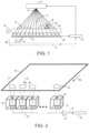
- FIG. 1 One version of an x-ray imaging apparatus embodying features of the invention is shown in FIG. 1 .
- An x-ray source 10 generates a bremsstrahlung beam 12 of x-ray photons having a source intensity distributed over a broad source spectrum.
- the x-ray source directs the beam of x-rays in a fan beam along an x-ray path 13 through a conveyor belt 14 in a line across the width of the belt.
- One example of an x-ray source is an x-ray tube with a tungsten target.
- the conveyor belt advances with product P in a conveying direction 16 out of the page in FIG. 1 .
- the x-rays 12 are attenuated by absorption as they pass through the conveyed product P and the conveyor belt 14.
- the attenuation depends on the thickness of the intervening material through which the x-rays pass from source to detector and on the attenuation coefficients of the various materials constituting the conveyor belt 14, the product P, and any other material that intersects the x-ray path 13.
- Spherical spreading of the x-rays along the x-ray path 13 also attenuates the x-ray intensity according to the inverse-square law, but that attenuation is set by the fixed distance between the x-ray source 10 and the detector 18 and so is known a priori and can be accounted for.
- the attenuated x-rays are received by a spectroscopic x-ray detector 18 on the opposite side of the conveyor belt 14 from the x-ray source 10.
- the spectroscopic x-ray detector 18 comprises a linear array of individual static x-ray-detecting pixels 20 that extend across the width of the belt 14.
- the pixels 20 can be solid-state cadmium telluride (CdTe) detectors.
- CDTe solid-state cadmium telluride
- Each pixel 20 produces a received energy spectrum binned in contiguous fixed-width bins, such as 1 keV-wide bins, at each pixel position across the width of the belt 14.
- the array of pixels 20 represents a line scan that measures the received x-ray intensity distributed across a received x-ray spectrum.
- the received x-ray spectra are sent to a processing system 22 that includes a programmable computer running software programs such as a two-dimensional (2D) imager, an x-ray source controller, and a user-interface controller.
- the x-ray source controller pulses the x-ray source 10 in synchrony with the sampling of the spectroscopic x-ray detector 18.
- An alternative x-ray detector 18' shown in dashed lines in FIG. 1 , comprises a single x-ray-detecting pixel 20' that is advanced rapidly across the width of the belt 14 as indicated by arrow 19 by a driver, such as a stator 21 forming a linear synchronous motor with a magnetic forcer in the pixel 20'.
- the pixel 20' advances rapidly across the width of the belt 14 as it samples the received x-ray intensity at discrete pixel positions and measures the energy spectrum at those positions across the belt width, such as the positions defined by the pixels 20 in the fixed-array x-ray detector 18.
- an array of multiple pixels spaced apart at regular intervals across the belt width could be advanced by a driver over just the regular interval rather than the entire width of the belt 14 to measure the spectra at the pixel positions.
- the processing system 22 receives the pixel spectra and controls the operation of the pixel driver 21 in the moving-pixel detectors.
- each pixel 20 has a collimator 24 defining a field of view 26 at each pixel position that intersects the conveyor belt 14 at its conveying surface 27 and eliminates scatter.
- the output signals of the pixels 20 are sent over signal lines 28 to signal-conditioning circuits 30 including buffers and analog-to-digital converters (ADCs).
- ADCs analog-to-digital converters
- Digital signals representing the received spectra are sent from the ADCs to the processing system 22 over digital lines 32.
- the distance 34 between laterally consecutive fields of view 26 is not greater than a predetermined detection threshold, i.e., the dimension of the smallest foreign object to be detected.
- FIG. 4 shows an example of the source x-ray spectrum for a tungsten x-ray tube and the attenuated received x-ray spectrum.
- FIG. 3 radiation interacts with matter in three ways: (1) the photoelectric effect 36, (2) Compton scattering 38, and (3) coherent scattering 40.
- the attenuation resulting from each of these effects for an exemplary material is a function of the x-ray energy E .
- the total attenuation coefficient ⁇ (E) is the sum of the attenuations due to the three effects as a function of the energy E .
- ⁇ decreases monotonically with increasing energy E for this exemplary material.
- FIG. 6 shows the relative attenuation coefficients of meat ( ⁇ M ), bone ( ⁇ B ), acetal ( ⁇ A ), steel ( ⁇ F ), and glass ( ⁇ G ).
- glass has an attenuation coefficient that does not decrease monotonically with increasing energy.
- the attenuation coefficient ⁇ ( E )-more strictly an attenuation function- is stored in tabular form in the processing system's memory or is computed algorithmically for each preselected constituent material of interest, i.e., those materials expected to be present: conveyor belt material; meat or other food product being conveyed; and the material constituting any other foreign object to be detected, such as a contaminant.
- All the ⁇ i ( E j ) attenuation coefficients are known and stored in the processing system's memory or calculated algorithmically by the processing system.
- the source intensity I s ( E j ) is known for each energy bin E j .
- the received intensity I r ( E j ) for each energy bin is measured by the spectroscopic x-ray detector each sample time.
- the ratio of the received intensity to the source intensity is the measured attenuation.
- the processing system solves the system of equations by regression to determine the thicknesses d i of each of the preselected constituent materials.
- the processing system uses a nonlinear regression, such as a least-squares regression.
- the Levenberg-Marquardt algorithm is one example of such a regression.
- the regression finds the best fit of the data to the attenuation model by minimizing the residuals of the d i material thickness terms.
- the resulting d i terms define the thickness of each of the preselected constituent materials for each pixel and, together with the calculated thicknesses for other samples, represent an image of the conveyor belt and the product and any other of the preselected constituent materials on the conveyor belt.
- the preselected constituent materials might be: (a) acetal (the conveyor belt material); (b) muscle (a product constituent); and (c) bone B (a product constituent).
- the calculated thickness of the acetal material is compared to the known thickness of the conveyor belt. If the calculated thickness is greater than the thickness of the belt 14, then a contaminating shard 42 of the acetal belt material is known to be present in the pixel's field of view. If additional potentially contaminating materials, such as glass, wood, and steel, are expected to possibly be present, their x-ray attenuation factors ⁇ can be added to the attenuation model to detect their thicknesses.
- the processing system 22 determines that a contaminant is present, its user-interface controller can sound an alarm 44, display an alarm condition on a monitor 46, send an alarm message to other locations over a hardwired or wireless network 48, or issue a divert signal 50 to a diverter 52 to divert a portion of product from the conveyor belt 14 to a reject conveyor 54, stop the conveyor, or take any other action required to ensure that the contaminated product is removed from the conveyor line.
- the distance 34 between consecutive fields of view 26 sets the detection threshold in the width direction of the conveyor belt 14.
- the detection threshold in the conveying direction is set by the product of the belt speed and the detector sampling interval. So the sampling rate must be high enough that the length of conveyor belt that passes the detector line from sample to sample does not exceed the detection threshold, i.e., the dimension in the conveyor direction of the smallest contaminant to be detected.
- the processing system can determine sizes of contaminants and product by analyzing the results of product thicknesses at contiguous pixel positions and on consecutive samples. With a table of densities of the preselected constituent materials, the processing system can estimate weights.
- the order of the materials along the path does not usually matter unless x-ray scattering by one or more of the materials is too great.
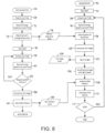
- FIGS. 7 and 8 are flowcharts illustrating one method of detecting materials by the x-ray imaging system of FIG. 1 .
- FIG. 7 is a flowchart of an exemplary process stored in program memory and executed by the processing system to generate the system of equations that constitute the attenuation model.
- the equations are set up by first, at step 60, selecting the constituent materials to be screened. The selection can be a fixed preselection of one or more materials or can be made by an operator over a user-interface device 56 in the user interface 58 ( FIG. 5 ).
- the attenuation coefficients ⁇ i (E j ) for the selected materials are imported from a library 62 of attenuation coefficients for a variety of materials stored in the processing system's memory. Or they can be manually entered from the user input device 56.
- the processing system then generates the system of equations with the attenuation coefficients ⁇ i (E j ) of the selected materials at step 64 to construct the model.
- the flowchart of FIG. 8 shows one version of a method executed by the processing system to detect suspected foreign objects on a conveyor belt.
- the first process (initialization 66) constructs a 2D image of an empty conveyor belt or conveyor-belt segment devoid of product. In the case of a belt with a regularly repeating belt pattern, as in most modular conveyor belts, a 2D image of a single belt row may suffice to define the entire belt.
- the processing system first pulses the x-ray source at step 68 and then records the received energy spectrum for each pixel position at step 70.
- the responses of the x-ray detector to the empty belt are used to compute calibration terms used to match the spectra bin-to-bin across the width of the belt so that all spectra are identical at step 72.
- the calibration terms are stored 74 in the processing system's memory for use in adjusting all the measured spectra to match.
- the initialization process then signals the belt motor to drive the conveyor belt at a constant speed at step 76.
- the x-ray source is pulsed at x-ray source controller step 78, and the received x-ray spectrum at each pixel position is measured and recorded at step 80 to produce a line scan.
- the process of pulsing the x-ray source 78 and recording the spectra 80 is repeated at a fixed pulse and sample rate to build up consecutive line scans until a repeating belt pattern is detected as indicated by step 82. If the belt is, for example, a flat belt of uniform thickness and construction with no repeating pattern, a uniform pattern can be used.
- the frame of line-scan spectra representing the repeating empty belt pattern is used to construct a 2D image of the pattern at step 84.
- the belt pattern is stored at step 86 for use 88 in the detection of foreign objects on the belt.
- the initialization process 66 can be run periodically to recalibrate the x-ray detector and to account for changes in the belt due to wear or module replacement.
- the processing system runs the acquisition process 90 on the conveyor belt running loaded with product.
- the process first starts the conveyor belt at step 92 and pulses the x-ray source at step 94.
- the energy spectrum at each pixel position is recorded at step 96.
- the system of equations representing the attenuation model for the selected constituent materials is solved for a line scan after the calibration terms 74 are applied to the energy spectra at step 98 to construct a 2D image of a frame consisting of consecutive line images at step 100.
- the 2D image is stored at step 102.
- the stored 2D image 104 is available for display.
- the frame image of the loaded belt is adjusted to match the frame length of the stored belt pattern or vice versa. And the loaded belt frame is synchronized, or aligned, with the empty belt pattern. Once that is done at step 106, the belt-pattern frame is subtracted from the loaded belt frame at step 108. The resulting difference provides the thicknesses of each of the preselected constituent materials at each pixel position in the frame. If any of the thicknesses exceeds an alarm threshold, a foreign-object-detection (FOD) alarm is sounded or other action is taken at step 110. If the belt is stopped at step 112, the acquisition process is exited. If the belt continues running, the process resumes in a regular repetitive fashion by pulsing the x-ray source again at step 94.
- FOD foreign-object-detection
- the processing system's initialization 66 and acquisition 90 processes can be implemented to run as individual sequential processes with program loops and delays to achieve the proper timing, the processes can alternatively be implemented-more consistent with realtime multi-tasking programming-using interrupt service routines and a task manager routine.
- the periodic pulsing of the x-ray source 94 and recording of the received energy spectra 96 could be implemented as an interrupt-service routine (ISR) scheduled to run at a preselected sampling rate.
- ISR interrupt-service routine
- the ISR could then bid the 2D imager task scheduled by the task manager to solve the system of equations 98, construct the 2D image 100, and store it 102 so that it can be displayed by a user-interface controller task.
- the 2D imager task could also synchronize the image with belt speed 106, subtract the stored empty belt pattern from the computed image 108, and generate FOD alarms 110. But those steps could alternatively be run in a separate task bid to run upon construction of the 2D image.
- the attenuation model was described as using fixed-width energy bins, it is possible to combine energy bins to form effectively wider energy bins than those automatically produced by the pixels. Because the attenuation of x-rays is greater at lower energy levels, the pixels' energy bins at lower energy levels could be combined to form wider energy bins to be used in the attenuation model. At the higher energies, the energy bins used in the system of equations need not be as wide as those at the lower energies. But because the attenuation curve is much steeper at low energies, wider bins increase the error in the estimates of the attenuation values to be assigned to wide low-energy bins.
- the widths of the bins are optimized so that the error term due to statistics (i.e., the count rate in an energy bin) and the estimation error in attenuation coefficient due to the steepness of the curve are approximately equal in magnitude.
- the x-ray imaging apparatus has been described mainly in reference to detecting contaminants, especially shards of conveyor belt, it can also be used to detect belt features, such as thickened portions of the belt, which the processing system could use as positional references to measure belt elongation or belt speed or to determine the location of contaminants on the belt. And if a longitudinal lane of the belt is maintained clear of product, pixels under that lane could be used to measure the source x-ray intensity and spectrum in real time.
Landscapes
- Health & Medical Sciences (AREA)
- Chemical & Material Sciences (AREA)
- Life Sciences & Earth Sciences (AREA)
- General Health & Medical Sciences (AREA)
- Analytical Chemistry (AREA)
- Biochemistry (AREA)
- Physics & Mathematics (AREA)
- General Physics & Mathematics (AREA)
- Immunology (AREA)
- Pathology (AREA)
- Toxicology (AREA)
- Engineering & Computer Science (AREA)
- Food Science & Technology (AREA)
- Medicinal Chemistry (AREA)
- Analysing Materials By The Use Of Radiation (AREA)
Claims (15)
- Vorrichtung zur Erkennung von Materialien auf einem Förderband, umfassend:Ein Förderband, dass so konfiguriert ist, dass es ein Produkt in eine Förderrichtung fördert;eine Röntgenquelle, die dazu konfiguriert ist, einen Strahl von Röntgenstrahlen mit einer über ein Quellenspektrum verteilten Quellenintensität durch die Dicke des Förderbandes entlang eines Röntgenpfads zu richten;einen spektroskopischen Röntgendetektor, der ein oder mehrere Pixel auf der Seite des Förderbandes umfasst, die der Röntgenquelle gegenüberliegt, welche die Röntgenstrahlen empfangen, die beim Durchgang durch das Förderband, das beförderte Produkt und irgendein sich mit dem beförderten Produkt auf dem Förderband bewegenden Fremdobjekt an diskreten Pixelpositionen über die Breite des Förderbandes abgeschwächt werden;wobei das eine oder mehrere Pixel ein entsprechendes Sichtfeld an jeder Pixelposition definieren und eine empfangene Intensität ermitteln, die über ein empfangenes Spektrum der abgeschwächten Röntgenstrahlen in ihrem entsprechenden Sichtfeld in jeder Pixelposition verteilt sind;ein Verarbeitungssystem, das so konfiguriert ist, dass es das empfangene Spektrum an jeder Pixelposition mit dem Quellenspektrum in Beziehung bringt, um eine gemessene Abschwächung der Röntgenstrahlen zu bestimmen, und die gemessene Abschwächung mit einem Röntgenabschwächungsmodell in Beziehung zu bringen, das Abschwächungskoeffizienten eines Satzes vorab ausgewählter Bestandteilmaterialien einschließt, die Materialien einschließen, aus denen das Produkt besteht, aus denen das Förderband besteht, und Materialien, die als mögliche Verunreinigungen vermutete Fremdkörper konstituieren, dadurch gekennzeichnet, dass das Verarbeitungssystem weiterhin so konfiguriert ist, dass es die Dicken jener Materialien in den Sichtfeldern an jeder Pixelposition bestimmt.
- Vorrichtung nach Anspruch 1, wobei das empfangene Spektrum an jeder Pixelposition in zusammenhängende Energiebehälter eingeteilt ist, und wobei das Verarbeitungssystem dazu konfiguriert ist, ein System von Abschwächungsgleichungen zu definieren, die das Verhältnis der empfangenen Intensität zur Quellenintensität in vorab ausgewählten Energiebehältern mit dem Röntgenabschwächungsmodell für die vorab ausgewählten Energiebehälter in Beziehung bringen, um die Dicke entlang des Röntgenpfads jedes der vorab ausgewählten Bestandteilmaterialien zu bestimmen.
- Vorrichtung nach Anspruch 2, wobei a) die vorab ausgewählten Energiebehälter einige oder alle der Energiebehälter umfassen; b) die Zahl der vorab ausgewählten Energiebehälter größer als oder gleich der Zahl vorab ausgewählter Bestandteilmaterialien ist; c) alle der Energiebehälter der gleichen Breite sind; oder d) die ausgewählten Energiebehälter breiter bei niedrigen Energieniveaus als bei höheren Energieniveaus sind.
- Vorrichtung nach Anspruch 2, wobei das Verarbeitungssystem so konfiguriert ist, dass es eine nicht lineare Regression am System von Gleichungen durchführt, um die beste Anpassung des Röntgenabschwächungsmodells an die Verhältnisse der empfangenen Intensität zur Quellenintensität in jedem der ausgewählten Energiebehälter zu bestimmen, indem der Restwert der Dicke entlang des Röntgenpfads jedes der vorab ausgewählten Bestanteilmaterialien minimiert wird.
- Vorrichtung nach Anspruch 4, wobei das System von Gleichungen eine Gleichung für jeden der vorab ausgewählten Energiebehälter der Form Σ N i=1 µ i d i= - In(Ir /Is ), einschließt, wobei N die Zahl von vorab ausgewählten Bestandteilmaterialien im Röntgenabschwächungsmodell ist, µi der Abschwächungskoeffizient des iten vorab ausgewählten Bestanteilmaterials für den Energiebehälter ist, di die Dicke entlang des Röntgenpfads des iten vorab ausgewählten Bestandteilmaterials ist, Ir die empfangene Röntgenintensität im Energiebehälter ist, und Is die Quellenröntgenintensität im Energiebehälter ist.
- Vorrichtung nach Anspruch 1, wobei der spektroskopische Röntgendetektor ein Einzelpixel oder eine Vielzahl beabstandeter Pixel und einen Treiber umfasst, der konfiguriert ist, das Einzelpixel oder die Vielzahl beabstandeter Pixel über die Breite des Förderbandes zu bewegen, um die Röntgenstrahlen an jeder Pixelposition zu empfangen.
- Vorrichtung nach Anspruch 1, wobei das Verarbeitungssystem konfiguriert ist, die Dicke des Bestandteilmaterials des Förderbandes entlang des Röntgenpfads für jede der Pixelpositionen zu bestimmen und jene Dicke mit einer vorbestimmten Dicke des Förderbandes entlang des Röntgenpfands zu vergleichen und das Vorhandensein eines kontaminierenden Stücks Förderbandmaterial anzuzeigen, wenn die ermittelte Dicke des Bestandteilmaterials des Förderbandes die vorbestimmte Dicke des Förderbandes überschreitet.
- Vorrichtung nach Anspruch 1, wobei das Verarbeitungssystem so konfiguriert ist, dass es Alarm schlägt, um einen Alarmzustand anzuzeigen, eine Alarmmeldung zu senden oder ein Umleitungssignal an eine Weiche auszugeben, um einen Teil des Produkts vom Förderband umzuleiten, nachdem das Vorhandensein einer Verunreinigung auf dem Förderband ermittelt worden ist.
- Vorrichtung nach Anspruch 1, wobei das Verarbeitungssystem dazu konfiguriert ist, die Röntgenquelle und die Proben des spektroskopischen Röntgendetektors synchron mit einer Rate zu pulsieren, die hoch genug ist, dass die Länge des Förderbands, da den spektroskopischen Röntgendetektor von Probe zu Probe passiert, nicht größer als ein vorbestimmter Erkennungsschwellenwert für die Verunreinigung ist.
- Vorrichtung nach Anspruch 1, wobei die entsprechenden Sichtfelder an aufeinander folgenden Pixelpositionen um einen Abstand getrennt sind, der nicht größer als ein vorbestimmter Erkennungsschwellenwert für die Verunreinigung ist; oder wobei sich das entsprechende Sichtfeld zumindest eines des einen oder der mehreren Pixel in einer Position in einer Längsspur des Förderbands befindet, die frei von Produkten gehalten wird.
- Verfahren zur Erkennung von Materialien auf einem Förderband, umfassend:Fördern eines Produkts auf einer Förderfläche in einer Förderrichtung;Richten von Quellenröntgenstrahlen mit einer über ein Quellenröntgenstrahlenspektrum verteilten Quellenintensität entlang eines Röntgenpfads durch die Förderfläche und das Produkt entlang einer Linie über die Breite der Förderfläche;Erkennen der beim Durchgang durch die Förderfläche abgeschwächten Röntgenstrahlen an einer Vielzahl von Pixelpositionen entlang der Linie mit einem spektroskopischen Röntgendetektor, der ein oder mehrere Pixel umfasst;Messen der Intensität der abgeschwächten Röntgenstrahlen in benachbarten Energiebehältern an jeder der Pixelpositionen, um ein empfangenes Röntgenspektrum an jeder der Pixelpositionen zu erzeugen;Beziehen des empfangenen Röntgenspektrums auf das Quellenröntgenspektrum, um eine gemessene Röntgenabschwächung zu bestimmen;Beziehen der gemessenen Röntgenabschwächung auf ein Röntgenabschwächungsmodell, das Abschwächungskoeffizienten eines Satzes von vorab ausgewählten Bestandteilmaterialien einschließt, die Materialien einschließen, die das Produkt konstituieren, Materialien, die das Förderband konstituieren und Materialien, die als mögliche Verunreinigungen vermutete Fremdkörper konstituieren, gekennzeichnet durch die weitere Bestimmung der Dicke jener Materialien in den Sichtfeldern jedes Pixels in der Linie.
- Verfahren nach Anspruch 11, umfassend das Definieren eines Systems von Abschwächungsgleichungen unter dem Abschwächungsmodell, die sich auf das Verhältnis der empfangenen Intensität zur Quellenintensität in einzelnen vorab ausgewählten Energiebehältern zum Röntgenabschwächungsmodell für jeden der vorab ausgewählten Energiebehälter bezieht, um die Dicke entlang des Röntgenpfads jedes der Bestandteilmaterialien zu bestimmen.
- Verfahren nach Anspruch 11, welches das Auswählen der Abschwächungskoeffizienten des Satzes von vorab ausgewählten Bestandteilmaterialien aus einer Bibliothek von Abschwächungskoeffizienten verschiedener Materialien umfasst.
- Verfahren nach Anspruch 11, welches das Erzeugen eines zweidimensionalen Bildes des Produkt tragenden Förderbands aus dem empfangenen Spektrum an jeder Pixelposition für aufeinander folgende Linien umfasst.
- Verfahren nach Anspruch 14, welches zunächst das Betreiben des Förderbands ohne Produkt und das Erzeugen eines leeren Bandmusters als ein zweidimensionales Bild des Förderbands ohne Produkt aus dem empfangenen Spektrum an jeder Pixelposition für aufeinander folgende Linien und Subtrahieren des leeren Bandmusters vom zweidimensionalen Bild des Förderbands mit Produkt umfasst, um das Vorhandensein der vorab ausgewählten Materialien zu bestimmen, die nicht Teil des Förderbands bilden.
Applications Claiming Priority (2)
| Application Number | Priority Date | Filing Date | Title |
|---|---|---|---|
| US201662427423P | 2016-11-29 | 2016-11-29 | |
| PCT/US2017/058025 WO2018102051A1 (en) | 2016-11-29 | 2017-10-24 | Multi-energy x-ray absorption imaging for detecting foreign objects on a conveyor |
Publications (3)
| Publication Number | Publication Date |
|---|---|
| EP3548877A1 EP3548877A1 (de) | 2019-10-09 |
| EP3548877A4 EP3548877A4 (de) | 2020-08-12 |
| EP3548877B1 true EP3548877B1 (de) | 2024-07-31 |
Family
ID=62242601
Family Applications (1)
| Application Number | Title | Priority Date | Filing Date |
|---|---|---|---|
| EP17876478.3A Active EP3548877B1 (de) | 2016-11-29 | 2017-10-24 | Multi-energie-röntgenabsorptionsbildgebung zur erkennung von fremdkörpern auf einem förderband |
Country Status (5)
| Country | Link |
|---|---|
| US (1) | US10761038B2 (de) |
| EP (1) | EP3548877B1 (de) |
| JP (1) | JP7198204B2 (de) |
| CN (1) | CN109997029B (de) |
| WO (1) | WO2018102051A1 (de) |
Families Citing this family (15)
| Publication number | Priority date | Publication date | Assignee | Title |
|---|---|---|---|---|
| GB2563006B (en) * | 2017-05-23 | 2021-03-31 | Cheyney Design & Dev Ltd | Improvements in or relating to detectors |
| EP3428629B1 (de) * | 2017-07-14 | 2022-12-07 | Malvern Panalytical B.V. | Analyse von röntgenspektren mittels kurvenanpassung |
| DE102019111567A1 (de) | 2019-05-03 | 2020-11-05 | Wipotec Gmbh | Verfahren und Vorrichtung zur Röntgeninspektion von Produkten, insbesondere von Lebensmitteln |
| DE102019111463A1 (de) | 2019-05-03 | 2020-11-05 | Wipotec Gmbh | Röntgenstrahlungsdetektorvorrichtung und Vorrichtung zur Röntgeninspektion von Produkten, insbesondere von Lebensmitteln |
| CN113359176B (zh) * | 2020-03-06 | 2022-10-04 | 台达电子工业股份有限公司 | X射线照影方法及其系统 |
| TWI781381B (zh) * | 2020-03-06 | 2022-10-21 | 台達電子工業股份有限公司 | X射線照影方法及其系統 |
| CN112285133A (zh) * | 2020-10-20 | 2021-01-29 | 苏州未艾视智能科技有限公司 | 一种x射线板坯成像仪及探测方法 |
| JP7480724B2 (ja) * | 2021-02-22 | 2024-05-10 | 株式会社島津製作所 | X線撮影装置およびx線撮影方法 |
| CN113848219A (zh) * | 2021-09-09 | 2021-12-28 | 齐鲁中科电工先进电磁驱动技术研究院 | 一种基于造布生产的调控方法、装置及造布调控系统 |
| CN114088742B (zh) * | 2021-11-18 | 2022-09-06 | 吉林大学 | 一种变矩器的铸造叶片塌陷位置检测装置 |
| CN118922711A (zh) * | 2022-03-24 | 2024-11-08 | 赛默飞世尔科学测量技术有限公司 | 衬底合金影响补偿 |
| WO2024086825A2 (en) * | 2022-10-20 | 2024-04-25 | Opentrons LabWorks Inc. | Compositions and systems for herpes simplex virus packaging and uses thereof |
| CA3268482A1 (en) | 2022-10-21 | 2024-04-25 | Sortera Technologies, Inc. | CORRECTION TECHNIQUES FOR MATERIALS CLASSIFICATION |
| EP4641185A1 (de) * | 2024-04-24 | 2025-10-29 | Sesotec GmbH | Verfahren und vorrichtung zur untersuchung von produkten |
| CN118465199B (zh) * | 2024-07-11 | 2024-11-12 | 江华新材料科技(江苏)有限公司 | 一种聚乳酸无纺布的抗菌性能检测方法及装置 |
Family Cites Families (29)
| Publication number | Priority date | Publication date | Assignee | Title |
|---|---|---|---|---|
| JPS59230146A (ja) * | 1983-06-13 | 1984-12-24 | Hitachi Ltd | 粉粒体の水分測定法 |
| JPH09145343A (ja) * | 1995-11-28 | 1997-06-06 | Toshiba Fa Syst Eng Kk | 放射線検査装置 |
| DE19605618A1 (de) * | 1996-02-15 | 1997-08-21 | Hauni Maschinenbau Ag | Verfahren und Vorrichtung zum Bestimmen der Dichte eines Faserstrangs der tabakverarbeitenden Industrie |
| JPH10246708A (ja) * | 1997-03-03 | 1998-09-14 | Hitachi Ltd | 非破壊検査装置及び方法 |
| US6449334B1 (en) | 2000-09-29 | 2002-09-10 | Lunar Corporation | Industrial inspection method and apparatus using dual energy x-ray attenuation |
| US6587575B1 (en) | 2001-02-09 | 2003-07-01 | The United States Of America As Represented By The Secretary Of Agriculture | Method and system for contaminant detection during food processing |
| US6370223B1 (en) | 2001-04-06 | 2002-04-09 | Ut-Battelle, Llc | Automatic detection of bone fragments in poultry using multi-energy x-rays |
| US6816571B2 (en) * | 2002-02-06 | 2004-11-09 | L-3 Communications Security And Detection Systems Corporation Delaware | Method and apparatus for transmitting information about a target object between a prescanner and a CT scanner |
| US8451974B2 (en) * | 2003-04-25 | 2013-05-28 | Rapiscan Systems, Inc. | X-ray tomographic inspection system for the identification of specific target items |
| US7480363B2 (en) | 2004-09-15 | 2009-01-20 | Ge Betz, Inc. | Converting a digital radiograph to an absolute thickness map |
| CN101322009B (zh) | 2005-11-16 | 2010-12-08 | 株式会社石田 | X射线检查装置 |
| US7742564B2 (en) * | 2006-01-24 | 2010-06-22 | The University Of North Carolina At Chapel Hill | Systems and methods for detecting an image of an object by use of an X-ray beam having a polychromatic distribution |
| EP1879020A1 (de) | 2006-07-12 | 2008-01-16 | Paul Scherrer Institut | Röntgenstrahlungsinterferometer für die Phasenkontrastbildgebung |
| GB0716045D0 (en) * | 2007-08-17 | 2007-09-26 | Durham Scient Crystals Ltd | Method and apparatus for inspection of materials |
| DE102007042144A1 (de) * | 2007-09-05 | 2009-03-12 | Smiths Heimann Gmbh | Verfahren zur Verbesserung der Materialerkennbarkeit in einer Röntgenprüfanlage und Röntgenprüfanlage |
| EP2382457A2 (de) * | 2009-01-27 | 2011-11-02 | Kromek Limited | Vorabtastung eines objekts in bewegung und nachfolgende lokalisierte abtastung des objekts in ruhestellung |
| EP2256069A1 (de) | 2009-05-29 | 2010-12-01 | Mettler-Toledo Safeline X-Ray Limited | Förderkette für ein Röntgenprüfsystem und Röntgenprüfsystem |
| JP2011024773A (ja) * | 2009-07-24 | 2011-02-10 | National Institute Of Advanced Industrial Science & Technology | X線成分計測装置 |
| FR2953603A1 (fr) * | 2009-12-09 | 2011-06-10 | Commissariat Energie Atomique | Procede et dispositif de reconnaissance d'un materiau a l'aide de sa fonction de transmission |
| GB201113138D0 (en) | 2011-07-29 | 2011-09-14 | Univ East Anglia | Method, system and device for detecting insects and other pests |
| WO2013017877A1 (en) | 2011-08-01 | 2013-02-07 | Kromek Limited | Detection and/or classification of materials |
| US9095146B2 (en) | 2011-08-12 | 2015-08-04 | Marcel Iceland Ehf | Meat inspection system |
| DE102012111494A1 (de) | 2012-11-27 | 2014-05-28 | Krones Ag | Vorrichtung und Verfahren zum Sterilisieren von Behältnissen mit Röntgenstrahlungsüberwachung |
| JP6092601B2 (ja) | 2012-12-03 | 2017-03-08 | 株式会社イシダ | X線検査装置 |
| CN103822929A (zh) * | 2014-02-13 | 2014-05-28 | 南京邮电大学 | 基于多能谱x射线的叠加目标分离成像方法 |
| AU2014268284A1 (en) * | 2014-11-30 | 2016-06-16 | Southern Innovation International Pty Ltd | Method and apparatus for material identification |
| DK3078944T3 (da) | 2015-04-07 | 2020-05-04 | Mettler Toledo Llc | Fremgangsmåde til bestemmelse af objekters masse ud fra en flerhed af røntgenbilleder taget ved forskellige energiniveauer |
| KR101930150B1 (ko) * | 2015-04-20 | 2018-12-17 | 가부시키가이샤 죠부 | X선 검사용의 데이터 처리 장치 및 데이터 처리 방법, 및, 그 장치를 탑재한 x선 검사 장치 |
| US9888894B2 (en) | 2015-12-21 | 2018-02-13 | General Electric Company | Multi-energy X-ray imaging |
-
2017
- 2017-10-24 EP EP17876478.3A patent/EP3548877B1/de active Active
- 2017-10-24 JP JP2019528503A patent/JP7198204B2/ja active Active
- 2017-10-24 CN CN201780073109.XA patent/CN109997029B/zh active Active
- 2017-10-24 US US16/346,823 patent/US10761038B2/en active Active
- 2017-10-24 WO PCT/US2017/058025 patent/WO2018102051A1/en not_active Ceased
Also Published As
| Publication number | Publication date |
|---|---|
| EP3548877A1 (de) | 2019-10-09 |
| EP3548877A4 (de) | 2020-08-12 |
| JP7198204B2 (ja) | 2022-12-28 |
| WO2018102051A1 (en) | 2018-06-07 |
| JP2019536043A (ja) | 2019-12-12 |
| US10761038B2 (en) | 2020-09-01 |
| US20190257773A1 (en) | 2019-08-22 |
| CN109997029B (zh) | 2022-12-13 |
| CN109997029A (zh) | 2019-07-09 |
Similar Documents
| Publication | Publication Date | Title |
|---|---|---|
| EP3548877B1 (de) | Multi-energie-röntgenabsorptionsbildgebung zur erkennung von fremdkörpern auf einem förderband | |
| US6370223B1 (en) | Automatic detection of bone fragments in poultry using multi-energy x-rays | |
| JP7024007B2 (ja) | X線放射検出装置、および製品を、特に食料品をx線検査する装置 | |
| EP0793804B2 (de) | Nachweis von sprengstoffen und anderer schmuggelware unter verwendung transmittierter und gestreuter röntgenstrahlung | |
| EP1950527B1 (de) | Röntgen-untersuchungseinrichtung | |
| EP3078944B1 (de) | Verfahren zur bestimmung der masse von gegenständen aus einer vielzahl von auf verschiedenen energiestufen aufgenommenen röntgenbildern | |
| US7164749B2 (en) | Method and apparatus for meat scanning | |
| CN101611296A (zh) | 重量检查装置和具有它的重量检查系统 | |
| JP5651007B2 (ja) | X線検査装置 | |
| JP6663374B2 (ja) | X線検査装置 | |
| JP6525512B2 (ja) | 物品分割前処理方法とその方法を実施するx線検査装置並びにその装置を使用した定量切り分けシステム | |
| KR100451537B1 (ko) | 방사선 검사장치 및 방사선 검사방법 | |
| AU2002339180A1 (en) | X-ray grading apparatus and process | |
| US9869642B2 (en) | Method for X-raying products | |
| JP2017006878A (ja) | 物品検査装置 | |
| JP7060446B2 (ja) | X線ラインセンサ及びそれを用いたx線異物検出装置 | |
| CN111954624A (zh) | 输送机系统 | |
| JP2004279059A (ja) | 放射線検査装置 | |
| WO2022138268A1 (ja) | X線照射ユニットを備えた装置のx線遮蔽構造 | |
| JP2016170110A (ja) | X線検査装置 | |
| JP2016090494A (ja) | X線検査装置 | |
| EP4610640A1 (de) | Röntgenrpüfgerät | |
| JP2011021920A (ja) | X線検査装置 | |
| JP3715528B2 (ja) | X線異物検出装置及び該装置における被検査物の移動停止検出方法 | |
| JP2002243664A (ja) | X線検査装置 |
Legal Events
| Date | Code | Title | Description |
|---|---|---|---|
| STAA | Information on the status of an ep patent application or granted ep patent |
Free format text: STATUS: THE INTERNATIONAL PUBLICATION HAS BEEN MADE |
|
| PUAI | Public reference made under article 153(3) epc to a published international application that has entered the european phase |
Free format text: ORIGINAL CODE: 0009012 |
|
| STAA | Information on the status of an ep patent application or granted ep patent |
Free format text: STATUS: REQUEST FOR EXAMINATION WAS MADE |
|
| 17P | Request for examination filed |
Effective date: 20190430 |
|
| AK | Designated contracting states |
Kind code of ref document: A1 Designated state(s): AL AT BE BG CH CY CZ DE DK EE ES FI FR GB GR HR HU IE IS IT LI LT LU LV MC MK MT NL NO PL PT RO RS SE SI SK SM TR |
|
| AX | Request for extension of the european patent |
Extension state: BA ME |
|
| DAV | Request for validation of the european patent (deleted) | ||
| DAX | Request for extension of the european patent (deleted) | ||
| A4 | Supplementary search report drawn up and despatched |
Effective date: 20200709 |
|
| RIC1 | Information provided on ipc code assigned before grant |
Ipc: G01N 23/18 20180101AFI20200704BHEP Ipc: G01N 23/04 20180101ALI20200704BHEP Ipc: G01N 33/12 20060101ALI20200704BHEP Ipc: G01N 23/087 20180101ALI20200704BHEP Ipc: G01N 21/89 20060101ALI20200704BHEP Ipc: G01N 21/84 20060101ALI20200704BHEP Ipc: G01N 21/88 20060101ALI20200704BHEP |
|
| STAA | Information on the status of an ep patent application or granted ep patent |
Free format text: STATUS: EXAMINATION IS IN PROGRESS |
|
| 17Q | First examination report despatched |
Effective date: 20220428 |
|
| GRAP | Despatch of communication of intention to grant a patent |
Free format text: ORIGINAL CODE: EPIDOSNIGR1 |
|
| STAA | Information on the status of an ep patent application or granted ep patent |
Free format text: STATUS: GRANT OF PATENT IS INTENDED |
|
| INTG | Intention to grant announced |
Effective date: 20240222 |
|
| GRAS | Grant fee paid |
Free format text: ORIGINAL CODE: EPIDOSNIGR3 |
|
| GRAA | (expected) grant |
Free format text: ORIGINAL CODE: 0009210 |
|
| STAA | Information on the status of an ep patent application or granted ep patent |
Free format text: STATUS: THE PATENT HAS BEEN GRANTED |
|
| P01 | Opt-out of the competence of the unified patent court (upc) registered |
Free format text: CASE NUMBER: APP_36221/2024 Effective date: 20240617 |
|
| AK | Designated contracting states |
Kind code of ref document: B1 Designated state(s): AL AT BE BG CH CY CZ DE DK EE ES FI FR GB GR HR HU IE IS IT LI LT LU LV MC MK MT NL NO PL PT RO RS SE SI SK SM TR |
|
| REG | Reference to a national code |
Ref country code: CH Ref legal event code: EP Ref country code: GB Ref legal event code: FG4D |
|
| REG | Reference to a national code |
Ref country code: DE Ref legal event code: R096 Ref document number: 602017083766 Country of ref document: DE |
|
| REG | Reference to a national code |
Ref country code: IE Ref legal event code: FG4D |
|
| REG | Reference to a national code |
Ref country code: LT Ref legal event code: MG9D |
|
| REG | Reference to a national code |
Ref country code: NL Ref legal event code: MP Effective date: 20240731 |
|
| PG25 | Lapsed in a contracting state [announced via postgrant information from national office to epo] |
Ref country code: PT Free format text: LAPSE BECAUSE OF FAILURE TO SUBMIT A TRANSLATION OF THE DESCRIPTION OR TO PAY THE FEE WITHIN THE PRESCRIBED TIME-LIMIT Effective date: 20241202 |
|
| REG | Reference to a national code |
Ref country code: AT Ref legal event code: MK05 Ref document number: 1708915 Country of ref document: AT Kind code of ref document: T Effective date: 20240731 |
|
| PG25 | Lapsed in a contracting state [announced via postgrant information from national office to epo] |
Ref country code: PT Free format text: LAPSE BECAUSE OF FAILURE TO SUBMIT A TRANSLATION OF THE DESCRIPTION OR TO PAY THE FEE WITHIN THE PRESCRIBED TIME-LIMIT Effective date: 20241202 |
|
| PGFP | Annual fee paid to national office [announced via postgrant information from national office to epo] |
Ref country code: DE Payment date: 20240913 Year of fee payment: 8 |
|
| PG25 | Lapsed in a contracting state [announced via postgrant information from national office to epo] |
Ref country code: NO Free format text: LAPSE BECAUSE OF FAILURE TO SUBMIT A TRANSLATION OF THE DESCRIPTION OR TO PAY THE FEE WITHIN THE PRESCRIBED TIME-LIMIT Effective date: 20241031 |
|
| PG25 | Lapsed in a contracting state [announced via postgrant information from national office to epo] |
Ref country code: NL Free format text: LAPSE BECAUSE OF FAILURE TO SUBMIT A TRANSLATION OF THE DESCRIPTION OR TO PAY THE FEE WITHIN THE PRESCRIBED TIME-LIMIT Effective date: 20240731 Ref country code: PL Free format text: LAPSE BECAUSE OF FAILURE TO SUBMIT A TRANSLATION OF THE DESCRIPTION OR TO PAY THE FEE WITHIN THE PRESCRIBED TIME-LIMIT Effective date: 20240731 Ref country code: GR Free format text: LAPSE BECAUSE OF FAILURE TO SUBMIT A TRANSLATION OF THE DESCRIPTION OR TO PAY THE FEE WITHIN THE PRESCRIBED TIME-LIMIT Effective date: 20241101 Ref country code: FI Free format text: LAPSE BECAUSE OF FAILURE TO SUBMIT A TRANSLATION OF THE DESCRIPTION OR TO PAY THE FEE WITHIN THE PRESCRIBED TIME-LIMIT Effective date: 20240731 |
|
| PG25 | Lapsed in a contracting state [announced via postgrant information from national office to epo] |
Ref country code: BG Free format text: LAPSE BECAUSE OF FAILURE TO SUBMIT A TRANSLATION OF THE DESCRIPTION OR TO PAY THE FEE WITHIN THE PRESCRIBED TIME-LIMIT Effective date: 20240731 |
|
| PG25 | Lapsed in a contracting state [announced via postgrant information from national office to epo] |
Ref country code: LV Free format text: LAPSE BECAUSE OF FAILURE TO SUBMIT A TRANSLATION OF THE DESCRIPTION OR TO PAY THE FEE WITHIN THE PRESCRIBED TIME-LIMIT Effective date: 20240731 |
|
| PG25 | Lapsed in a contracting state [announced via postgrant information from national office to epo] |
Ref country code: IS Free format text: LAPSE BECAUSE OF FAILURE TO SUBMIT A TRANSLATION OF THE DESCRIPTION OR TO PAY THE FEE WITHIN THE PRESCRIBED TIME-LIMIT Effective date: 20241130 Ref country code: AT Free format text: LAPSE BECAUSE OF FAILURE TO SUBMIT A TRANSLATION OF THE DESCRIPTION OR TO PAY THE FEE WITHIN THE PRESCRIBED TIME-LIMIT Effective date: 20240731 |
|
| PG25 | Lapsed in a contracting state [announced via postgrant information from national office to epo] |
Ref country code: HR Free format text: LAPSE BECAUSE OF FAILURE TO SUBMIT A TRANSLATION OF THE DESCRIPTION OR TO PAY THE FEE WITHIN THE PRESCRIBED TIME-LIMIT Effective date: 20240731 |
|
| PG25 | Lapsed in a contracting state [announced via postgrant information from national office to epo] |
Ref country code: ES Free format text: LAPSE BECAUSE OF FAILURE TO SUBMIT A TRANSLATION OF THE DESCRIPTION OR TO PAY THE FEE WITHIN THE PRESCRIBED TIME-LIMIT Effective date: 20240731 Ref country code: RS Free format text: LAPSE BECAUSE OF FAILURE TO SUBMIT A TRANSLATION OF THE DESCRIPTION OR TO PAY THE FEE WITHIN THE PRESCRIBED TIME-LIMIT Effective date: 20241031 |
|
| PG25 | Lapsed in a contracting state [announced via postgrant information from national office to epo] |
Ref country code: RS Free format text: LAPSE BECAUSE OF FAILURE TO SUBMIT A TRANSLATION OF THE DESCRIPTION OR TO PAY THE FEE WITHIN THE PRESCRIBED TIME-LIMIT Effective date: 20241031 Ref country code: PL Free format text: LAPSE BECAUSE OF FAILURE TO SUBMIT A TRANSLATION OF THE DESCRIPTION OR TO PAY THE FEE WITHIN THE PRESCRIBED TIME-LIMIT Effective date: 20240731 Ref country code: NO Free format text: LAPSE BECAUSE OF FAILURE TO SUBMIT A TRANSLATION OF THE DESCRIPTION OR TO PAY THE FEE WITHIN THE PRESCRIBED TIME-LIMIT Effective date: 20241031 Ref country code: NL Free format text: LAPSE BECAUSE OF FAILURE TO SUBMIT A TRANSLATION OF THE DESCRIPTION OR TO PAY THE FEE WITHIN THE PRESCRIBED TIME-LIMIT Effective date: 20240731 Ref country code: LV Free format text: LAPSE BECAUSE OF FAILURE TO SUBMIT A TRANSLATION OF THE DESCRIPTION OR TO PAY THE FEE WITHIN THE PRESCRIBED TIME-LIMIT Effective date: 20240731 Ref country code: IS Free format text: LAPSE BECAUSE OF FAILURE TO SUBMIT A TRANSLATION OF THE DESCRIPTION OR TO PAY THE FEE WITHIN THE PRESCRIBED TIME-LIMIT Effective date: 20241130 Ref country code: HR Free format text: LAPSE BECAUSE OF FAILURE TO SUBMIT A TRANSLATION OF THE DESCRIPTION OR TO PAY THE FEE WITHIN THE PRESCRIBED TIME-LIMIT Effective date: 20240731 Ref country code: GR Free format text: LAPSE BECAUSE OF FAILURE TO SUBMIT A TRANSLATION OF THE DESCRIPTION OR TO PAY THE FEE WITHIN THE PRESCRIBED TIME-LIMIT Effective date: 20241101 Ref country code: FI Free format text: LAPSE BECAUSE OF FAILURE TO SUBMIT A TRANSLATION OF THE DESCRIPTION OR TO PAY THE FEE WITHIN THE PRESCRIBED TIME-LIMIT Effective date: 20240731 Ref country code: ES Free format text: LAPSE BECAUSE OF FAILURE TO SUBMIT A TRANSLATION OF THE DESCRIPTION OR TO PAY THE FEE WITHIN THE PRESCRIBED TIME-LIMIT Effective date: 20240731 Ref country code: BG Free format text: LAPSE BECAUSE OF FAILURE TO SUBMIT A TRANSLATION OF THE DESCRIPTION OR TO PAY THE FEE WITHIN THE PRESCRIBED TIME-LIMIT Effective date: 20240731 Ref country code: AT Free format text: LAPSE BECAUSE OF FAILURE TO SUBMIT A TRANSLATION OF THE DESCRIPTION OR TO PAY THE FEE WITHIN THE PRESCRIBED TIME-LIMIT Effective date: 20240731 |
|
| PG25 | Lapsed in a contracting state [announced via postgrant information from national office to epo] |
Ref country code: SM Free format text: LAPSE BECAUSE OF FAILURE TO SUBMIT A TRANSLATION OF THE DESCRIPTION OR TO PAY THE FEE WITHIN THE PRESCRIBED TIME-LIMIT Effective date: 20240731 Ref country code: RO Free format text: LAPSE BECAUSE OF FAILURE TO SUBMIT A TRANSLATION OF THE DESCRIPTION OR TO PAY THE FEE WITHIN THE PRESCRIBED TIME-LIMIT Effective date: 20240731 Ref country code: DK Free format text: LAPSE BECAUSE OF FAILURE TO SUBMIT A TRANSLATION OF THE DESCRIPTION OR TO PAY THE FEE WITHIN THE PRESCRIBED TIME-LIMIT Effective date: 20240731 |
|
| PG25 | Lapsed in a contracting state [announced via postgrant information from national office to epo] |
Ref country code: EE Free format text: LAPSE BECAUSE OF FAILURE TO SUBMIT A TRANSLATION OF THE DESCRIPTION OR TO PAY THE FEE WITHIN THE PRESCRIBED TIME-LIMIT Effective date: 20240731 |
|
| PG25 | Lapsed in a contracting state [announced via postgrant information from national office to epo] |
Ref country code: CZ Free format text: LAPSE BECAUSE OF FAILURE TO SUBMIT A TRANSLATION OF THE DESCRIPTION OR TO PAY THE FEE WITHIN THE PRESCRIBED TIME-LIMIT Effective date: 20240731 |
|
| PG25 | Lapsed in a contracting state [announced via postgrant information from national office to epo] |
Ref country code: IT Free format text: LAPSE BECAUSE OF FAILURE TO SUBMIT A TRANSLATION OF THE DESCRIPTION OR TO PAY THE FEE WITHIN THE PRESCRIBED TIME-LIMIT Effective date: 20240731 Ref country code: SK Free format text: LAPSE BECAUSE OF FAILURE TO SUBMIT A TRANSLATION OF THE DESCRIPTION OR TO PAY THE FEE WITHIN THE PRESCRIBED TIME-LIMIT Effective date: 20240731 |
|
| REG | Reference to a national code |
Ref country code: DE Ref legal event code: R097 Ref document number: 602017083766 Country of ref document: DE |
|
| REG | Reference to a national code |
Ref country code: CH Ref legal event code: PL |
|
| PLBE | No opposition filed within time limit |
Free format text: ORIGINAL CODE: 0009261 |
|
| STAA | Information on the status of an ep patent application or granted ep patent |
Free format text: STATUS: NO OPPOSITION FILED WITHIN TIME LIMIT |
|
| PG25 | Lapsed in a contracting state [announced via postgrant information from national office to epo] |
Ref country code: MC Free format text: LAPSE BECAUSE OF FAILURE TO SUBMIT A TRANSLATION OF THE DESCRIPTION OR TO PAY THE FEE WITHIN THE PRESCRIBED TIME-LIMIT Effective date: 20240731 |
|
| 26N | No opposition filed |
Effective date: 20250501 |
|
| PG25 | Lapsed in a contracting state [announced via postgrant information from national office to epo] |
Ref country code: BE Free format text: LAPSE BECAUSE OF NON-PAYMENT OF DUE FEES Effective date: 20241031 Ref country code: LU Free format text: LAPSE BECAUSE OF NON-PAYMENT OF DUE FEES Effective date: 20241024 |
|
| PG25 | Lapsed in a contracting state [announced via postgrant information from national office to epo] |
Ref country code: CH Free format text: LAPSE BECAUSE OF NON-PAYMENT OF DUE FEES Effective date: 20241031 |
|
| REG | Reference to a national code |
Ref country code: BE Ref legal event code: MM Effective date: 20241031 |
|
| PG25 | Lapsed in a contracting state [announced via postgrant information from national office to epo] |
Ref country code: SE Free format text: LAPSE BECAUSE OF FAILURE TO SUBMIT A TRANSLATION OF THE DESCRIPTION OR TO PAY THE FEE WITHIN THE PRESCRIBED TIME-LIMIT Effective date: 20240731 |
|
| PGFP | Annual fee paid to national office [announced via postgrant information from national office to epo] |
Ref country code: GB Payment date: 20250911 Year of fee payment: 9 |
|
| PGFP | Annual fee paid to national office [announced via postgrant information from national office to epo] |
Ref country code: FR Payment date: 20250912 Year of fee payment: 9 |
|
| PG25 | Lapsed in a contracting state [announced via postgrant information from national office to epo] |
Ref country code: IE Free format text: LAPSE BECAUSE OF NON-PAYMENT OF DUE FEES Effective date: 20241024 |