EP4501522A1 - Laserschneidverfahren und laserschneidvorrichtung - Google Patents
Laserschneidverfahren und laserschneidvorrichtung Download PDFInfo
- Publication number
- EP4501522A1 EP4501522A1 EP23780572.6A EP23780572A EP4501522A1 EP 4501522 A1 EP4501522 A1 EP 4501522A1 EP 23780572 A EP23780572 A EP 23780572A EP 4501522 A1 EP4501522 A1 EP 4501522A1
- Authority
- EP
- European Patent Office
- Prior art keywords
- scanning
- front surface
- laser cutting
- spots
- beams
- Prior art date
- Legal status (The legal status is an assumption and is not a legal conclusion. Google has not performed a legal analysis and makes no representation as to the accuracy of the status listed.)
- Pending
Links
Images


Classifications
-
- B—PERFORMING OPERATIONS; TRANSPORTING
- B23—MACHINE TOOLS; METAL-WORKING NOT OTHERWISE PROVIDED FOR
- B23K—SOLDERING OR UNSOLDERING; WELDING; CLADDING OR PLATING BY SOLDERING OR WELDING; CUTTING BY APPLYING HEAT LOCALLY, e.g. FLAME CUTTING; WORKING BY LASER BEAM
- B23K26/00—Working by laser beam, e.g. welding, cutting or boring
- B23K26/36—Removing material
- B23K26/38—Removing material by boring or cutting
-
- B—PERFORMING OPERATIONS; TRANSPORTING
- B23—MACHINE TOOLS; METAL-WORKING NOT OTHERWISE PROVIDED FOR
- B23K—SOLDERING OR UNSOLDERING; WELDING; CLADDING OR PLATING BY SOLDERING OR WELDING; CUTTING BY APPLYING HEAT LOCALLY, e.g. FLAME CUTTING; WORKING BY LASER BEAM
- B23K26/00—Working by laser beam, e.g. welding, cutting or boring
- B23K26/02—Positioning or observing the workpiece, e.g. with respect to the point of impact; Aligning, aiming or focusing the laser beam
- B23K26/06—Shaping the laser beam, e.g. by masks or multi-focusing
- B23K26/0604—Shaping the laser beam, e.g. by masks or multi-focusing by a combination of beams
- B23K26/0608—Shaping the laser beam, e.g. by masks or multi-focusing by a combination of beams in the same heat affected zone [HAZ]
-
- B—PERFORMING OPERATIONS; TRANSPORTING
- B23—MACHINE TOOLS; METAL-WORKING NOT OTHERWISE PROVIDED FOR
- B23K—SOLDERING OR UNSOLDERING; WELDING; CLADDING OR PLATING BY SOLDERING OR WELDING; CUTTING BY APPLYING HEAT LOCALLY, e.g. FLAME CUTTING; WORKING BY LASER BEAM
- B23K26/00—Working by laser beam, e.g. welding, cutting or boring
- B23K26/02—Positioning or observing the workpiece, e.g. with respect to the point of impact; Aligning, aiming or focusing the laser beam
- B23K26/06—Shaping the laser beam, e.g. by masks or multi-focusing
- B23K26/064—Shaping the laser beam, e.g. by masks or multi-focusing by means of optical elements, e.g. lenses, mirrors or prisms
- B23K26/0648—Shaping the laser beam, e.g. by masks or multi-focusing by means of optical elements, e.g. lenses, mirrors or prisms comprising lenses
-
- B—PERFORMING OPERATIONS; TRANSPORTING
- B23—MACHINE TOOLS; METAL-WORKING NOT OTHERWISE PROVIDED FOR
- B23K—SOLDERING OR UNSOLDERING; WELDING; CLADDING OR PLATING BY SOLDERING OR WELDING; CUTTING BY APPLYING HEAT LOCALLY, e.g. FLAME CUTTING; WORKING BY LASER BEAM
- B23K26/00—Working by laser beam, e.g. welding, cutting or boring
- B23K26/02—Positioning or observing the workpiece, e.g. with respect to the point of impact; Aligning, aiming or focusing the laser beam
- B23K26/06—Shaping the laser beam, e.g. by masks or multi-focusing
- B23K26/067—Dividing the beam into multiple beams, e.g. multi-focusing
- B23K26/0676—Dividing the beam into multiple beams, e.g. multi-focusing into dependently operating sub-beams, e.g. an array of spots with fixed spatial relationship or for performing simultaneously identical operations
-
- B—PERFORMING OPERATIONS; TRANSPORTING
- B23—MACHINE TOOLS; METAL-WORKING NOT OTHERWISE PROVIDED FOR
- B23K—SOLDERING OR UNSOLDERING; WELDING; CLADDING OR PLATING BY SOLDERING OR WELDING; CUTTING BY APPLYING HEAT LOCALLY, e.g. FLAME CUTTING; WORKING BY LASER BEAM
- B23K26/00—Working by laser beam, e.g. welding, cutting or boring
- B23K26/08—Devices involving relative movement between laser beam and workpiece
- B23K26/082—Scanning systems, i.e. devices involving movement of the laser beam relative to the laser head
-
- B—PERFORMING OPERATIONS; TRANSPORTING
- B23—MACHINE TOOLS; METAL-WORKING NOT OTHERWISE PROVIDED FOR
- B23K—SOLDERING OR UNSOLDERING; WELDING; CLADDING OR PLATING BY SOLDERING OR WELDING; CUTTING BY APPLYING HEAT LOCALLY, e.g. FLAME CUTTING; WORKING BY LASER BEAM
- B23K2101/00—Articles made by soldering, welding or cutting
- B23K2101/36—Electric or electronic devices
- B23K2101/38—Conductors
-
- B—PERFORMING OPERATIONS; TRANSPORTING
- B23—MACHINE TOOLS; METAL-WORKING NOT OTHERWISE PROVIDED FOR
- B23K—SOLDERING OR UNSOLDERING; WELDING; CLADDING OR PLATING BY SOLDERING OR WELDING; CUTTING BY APPLYING HEAT LOCALLY, e.g. FLAME CUTTING; WORKING BY LASER BEAM
- B23K2103/00—Materials to be soldered, welded or cut
- B23K2103/08—Non-ferrous metals or alloys
- B23K2103/10—Aluminium or alloys thereof
-
- B—PERFORMING OPERATIONS; TRANSPORTING
- B23—MACHINE TOOLS; METAL-WORKING NOT OTHERWISE PROVIDED FOR
- B23K—SOLDERING OR UNSOLDERING; WELDING; CLADDING OR PLATING BY SOLDERING OR WELDING; CUTTING BY APPLYING HEAT LOCALLY, e.g. FLAME CUTTING; WORKING BY LASER BEAM
- B23K2103/00—Materials to be soldered, welded or cut
- B23K2103/08—Non-ferrous metals or alloys
- B23K2103/12—Copper or alloys thereof
-
- Y—GENERAL TAGGING OF NEW TECHNOLOGICAL DEVELOPMENTS; GENERAL TAGGING OF CROSS-SECTIONAL TECHNOLOGIES SPANNING OVER SEVERAL SECTIONS OF THE IPC; TECHNICAL SUBJECTS COVERED BY FORMER USPC CROSS-REFERENCE ART COLLECTIONS [XRACs] AND DIGESTS
- Y02—TECHNOLOGIES OR APPLICATIONS FOR MITIGATION OR ADAPTATION AGAINST CLIMATE CHANGE
- Y02E—REDUCTION OF GREENHOUSE GAS [GHG] EMISSIONS, RELATED TO ENERGY GENERATION, TRANSMISSION OR DISTRIBUTION
- Y02E60/00—Enabling technologies; Technologies with a potential or indirect contribution to GHG emissions mitigation
- Y02E60/10—Energy storage using batteries
Definitions
- the present invention relates to a laser cutting method and a laser cutting apparatus.
- the laser cutting is a method of irradiating a portion of a workpiece which is to be cut with laser light, melting the portion with energy of the laser light, and cutting the workpiece (see, for example, Non Patent Literature 1).
- Non Patent Literature 1 Patwa, Rahul, et al. "High speed laser cutting of electrodes for advanced batteries.” International Congress on Applications of Lasers & Electro Optics. 2010 .
- a workpiece is a metal foil
- one of objects of the present invention is to obtain both an improved novel laser cutting method and laser cutting apparatus capable of forming a higher-quality edge even in the case where the workpiece is a metal foil, for example.
- a laser cutting method includes: performing laser cutting on a metal foil by scanning, on a front surface of the metal foil with respect to the front surface, the front surface while irradiating the front surface with laser light, wherein the laser light includes a plurality of beams, and the plurality of beams are arranged to form a spot group including a plurality of spots separated in a relative scanning direction on the front surface.
- a power of an individual one of the beams forming the plurality of respective spots included in the spot group on the front surface may be set to a magnitude with which scanning with the individual one beam at a predetermined speed in the scanning direction does not enable the metal foil to be cut, and a power of the plurality of beams forming the plurality of spots included in the spot group on the front surface may be set to a magnitude with which scanning with the plurality of beams at the predetermined speed in the scanning direction enables the metal foil to be cut.
- a scanning path of each of the beams on the front surface includes a plurality of zones in which scanning may be performed in different scanning directions, and the plurality of beams may be arranged to form, as the spot group, a plurality of spot groups including a plurality of spots separated in scanning directions of the plurality of respective zones.
- the scanning path may include two zones in which scanning is performed in scanning directions orthogonal to each other.
- the scanning path may include three or more zones in which the scanning is performed in scanning directions intersecting each other.
- the plurality of spot groups may be arranged such that geometric centers of spots formed on the front surface substantially coincide with each other.
- a distance from a geometric center of a plurality of spots formed on the front surface to a center of each of the spots may be 30 ⁇ m or longer and 75 ⁇ m or shorter.
- the plurality of spots may include a first spot and a plurality of second spots provided around the first spot, and a ratio of a power of the first spot to a total power of the plurality of spots may be 50% or higher and 80% or lower.
- the plurality of beams may be formed by a beam shaper.
- the beam shaper may be a diffractive optical grating.
- the metal foil may include a base metal and a covering layer covering at least one of a front surface and a back surface of the base metal.
- the metal foil may include the base metal and two covering layers covering the front surface and the back surface of the base metal.
- the scanning path of each of the beams on the front surface may include a zone passing through a first portion in which both the front surface and the back surface of the base metal are not covered with the covering layer, and a zone passing through a second portion in which at least one of the front surface and the back surface of the base metal is covered with the covering layer, and the first portion and the second portion may be consecutively cut.
- irradiation conditions of the laser light may be same in both the zone passing through the first portion and the zone passing through the second portion, of the scanning path.
- the base metal may be any one of an aluminum-based metal material, a copper-based metal material, and a nickel-based metal material.
- the covering layer may be any one of lithiated transition metal oxides NCA (LiNiCoAlO 2 ) or NCM (LiNiCoMnO 2 ), carbon black, a polymer binder, LiMn 2 O 4 , LiFePO 4 , LiNiO 2 , LiMnO 2 , LiCoO 2 , and lithium sulfur (Li 2 S).
- NCA LiNiCoAlO 2
- NCM LiNiCoMnO 2
- carbon black a polymer binder
- LiMn 2 O 4 LiFePO 4
- LiNiO 2 , LiMnO 2 , LiCoO 2 LiCoO 2
- Li 2 S lithium sulfur
- a laser cutting apparatus includes: a laser oscillator; and an optical head configured to emit laser light output from the laser oscillator, wherein laser cutting is performed on a metal foil by scanning, on a front surface of the metal foil with respect to the front surface, the front surface while irradiating the front surface with the laser light, the laser light includes a plurality of beams, and the plurality of beams are arranged to form a spot group including a plurality of spots separated in a relative scanning direction on the front surface.
- the above-described laser cutting apparatus may include a beam shaper configured to form the plurality of beams.
- the beam shaper may be a diffractive optical grating.
- both an improved novel laser cutting method and laser cutting device can be obtained.
- Embodiments to be described below have similar configurations. Hence, according to a configuration of each embodiment, a similar operation and effect based on the similar configuration can be obtained.
- the same reference numerals are assigned to the same configurations, and redundant description thereof may be omitted.
- an X direction is represented by an arrow X
- a Y direction is represented by an arrow Y
- a Z direction is represented by an arrow Z.
- the X direction, the Y direction, and the Z direction intersect each other and are orthogonal to each other.
- the X direction and the Y direction are directions along a front surface Wa (processing surface) of a workpiece W
- the Z direction is a normal direction of the front surface Wa.
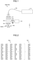
- FIG. 1 is a schematic configuration diagram of a laser cutting apparatus 100A (100) of a first embodiment.
- the laser cutting apparatus 100 includes a laser device 110, an optical head 120, an optical fiber 130, and a moving mechanism 140.
- the laser device 110 includes a laser oscillator as a light source and is configured to be able to output laser light having a power of several kilowatts, for example.
- a wavelength of the laser light output from the laser device 110 is, for example, 800 [nm] or longer and 1,200 [nm] or shorter, but is not limited thereto.
- the laser device 110 can intermittently output continuous-wave laser light at a frequency of 10 [MHz] or lower, for example.
- the optical fiber 130 optically connects the laser device 110 and the optical head 120 and guides laser light output from the laser device 110 to the optical head 120.
- the optical fiber 130 is configured to transmit the single-mode laser light.
- the M 2 beam quality of the single-mode laser light is set to 1.2 or lower.
- the optical fiber 130 is configured to transmit the multi-mode laser light.
- the optical head 120 is an optical device for irradiating the front surface Wa of the workpiece W with the laser light input from the laser device 110.
- the optical head 120 includes a collimating lens 121, a condenser lens 122, and a diffractive optical element (DOE) 123.
- the collimating lens 121 and the condenser lens 122 may also be referred to as optical components.
- the optical head 120 may have optical components other than the collimating lens 121 and the condenser lens 122.
- the collimating lens 121 collimates the input laser light.
- the collimated laser light becomes parallel light.
- the condenser lens 122 condenses laser light as parallel light and irradiates the workpiece W with the laser light as laser light L (output light).
- the DOE 123 is disposed between the collimating lens 121 and the condenser lens 122.
- FIG. 2 is an illustrative view of a concept of a principle of the DOE 123.
- the DOE 123 has, for example, a configuration in which a plurality of diffraction gratings 123a having different periods is overlapped.
- the DOE 123 bends or overlaps rays of the parallel light in a direction in which the parallel light is affected by the diffraction gratings 123a, thereby enabling the laser light to branch into a plurality of beams and enabling specifications such as the number of the plurality of beams, a relative arrangement, and shapes of the respective beams to be defined.
- the front surface Wa of the workpiece W is irradiated with the laser light L including the plurality of branched beams from the optical head 120, and thereby spots corresponding to the respective beams are formed on the front surface Wa. That is, the DOE 123 defines specifications such as the number of spots formed on the front surface Wa, a relative arrangement, shapes of the respective spots, and the like. In addition, by replacing the DOE 123 in the optical head 120, spots having various specifications can be formed on the front surface Wa.
- the optical head 120 may be configured to support the DOE 123 rotatably about an optical axis and be able to change a corresponding rotation angle. In this case, a pattern of the spots can be rotated on the front surface Wa.
- the optical head 120 irradiates the front surface Wa of the workpiece W with the laser light L in a direction opposite to the Z direction.
- An irradiation direction of the laser light L from the optical head 120 is the direction opposite to the Z direction.
- the optical head 120 can condense the laser light L such that a beam diameter is 10 [ ⁇ m] or larger and 100 [ ⁇ m] or smaller.
- the optical head 120 is configured to be able to change a relative position with respect to the workpiece W since scanning is performed with the laser light L while the irradiation with the laser light L is performed on the front surface Wa of the workpiece W.
- the moving mechanism 140 can move the optical head 120 in a direction intersecting the Z direction, in other words, in a direction along the front surface Wa.
- the workpiece W may be transported in a direction intersecting the Z direction by a transport mechanism (not illustrated).
- the relative movement of the optical head 120 and the workpiece W with respect to each other is realized by the movement of the optical head 120, the movement of the workpiece W, or the movement of both the optical head 120 and the workpiece W.
- FIG. 3 is a cross-sectional view of a metal foil 10 as the workpiece W
- FIG. 4 is a plan view of the metal foil 10, the plan view including a scanning path Pt1 of a spot of laser light.
- the scanning path Pt1 is a movement path of a geometric center of one or more spots.
- the workpiece W of the laser cutting apparatus 100 is the metal foil 10 which is applied to an electrode of a battery.
- a thickness of the metal foil 10 is, for example, 500 [ ⁇ m] or less, but is not limited thereto.
- the metal foil 10 includes a base metal 11 and active material layers 12.
- the active material layers 12 are covering layers formed on both sides of the base metal 11 in a thickness direction, that is, both front and back surfaces of the base metal 11.
- the active material layer 12 may also be referred to as a coating film, a coating material, a surface layer, or a surface layer material.
- the metal foil 10 constitutes, for example, an electrode of a battery such as a lithium ion battery.
- the base metal 11 is made of, for example, any one of an aluminum-based metal material, a copper-based metal material, and a nickel-based metal material.
- the active material layer 12 is made of, for example, any one of lithiated transition metal oxides NCA (LiNiCoAlO 2 ) or NCM (LiNiCoMnO 2 ), carbon black, a polymer binder, LiMn 2 O 4 , LiFePO 4 , LiNiO 2 , LiMnO 2 , LiCoO 2 , and lithium sulfur (Li 2 S).
- the base metal 11 may be covered with an insulating layer as a covering layer different from the active material layer 12. In this case, the insulating layer may cover the base metal 11 at a position away from the active material layer 12.
- the covering layer such as the active material layer 12 may cover only one of the front surface and the back surface of the base metal 11.
- the base metal 11 is also referred to as a metal layer.
- a covered part Pc where the base metal 11 is covered with the active material layer 12, that is, the covering layer, and an exposed part Pe where the base metal 11 is exposed without being covered with the active material layer 12 are formed.
- the laser cutting apparatus 100 can continuously cut both the covered part Pc and the exposed part Pe by performing scanning with the laser light L along the predetermined scanning path Pt1 on the front surface Wa of the metal foil 10.
- a portion where the active material layer 12 is not formed on both the front surface that is an end surface of the base metal 11 in the Z direction and the back surface directing toward a direction opposite to the Z direction on a side opposite to the front surface is referred to as a first portion
- a portion where the active material layer 12 is formed on at least one of the front surface and the back surface of the base metal 11 is referred to as a second portion.
- the exposed part Pe is an example of the first portion
- the covered part Pc is an example of the second portion.
- the scanning path Pt1 has a rectangular wave shape as a whole and repeatedly includes a plurality of zones P1 to P4.
- the zone P1 is a zone in which the scanning of the front surface Wa is performed in a scanning direction D1 by a predetermined length from an end point of the zone P4.
- the zone P2 is a zone in which the scanning is performed in a scanning direction D2 by a predetermined length from an end point of the zone P1.
- the zone P3 is a zone in which the scanning is performed in a scanning direction D3 by a predetermined length from an end point of the zone P2.
- the zone P4 is a zone in which the scanning is performed in a scanning direction D4 by a predetermined length from an end point of the zone P3.
- the scanning direction D2 intersects and is orthogonal to the scanning direction D1
- the scanning direction D3 intersects and is orthogonal to the scanning direction D2
- the scanning direction D4 intersects and is orthogonal to the scanning direction D3
- the scanning direction D1 intersects and is orthogonal to the scanning direction D4.
- the scanning direction D1 and the scanning direction D3 are parallel to each other, and the scanning direction D2 and the scanning direction D4 are antiparallel to each other.
- the scanning path Pt1 includes two zones (P1, P2, and the like) in which the scanning is performed in the scanning directions (D1, D2, and the like) orthogonal to each other and includes a plurality of zones P1 (P3), P2, and P4 in which the scanning is performed in the scanning directions D1 (D3), D2, and D4 different from each other.
- the scanning directions D1 and D3 are examples of a longitudinal direction of an edge 10a extending long along the scanning path Pt1
- the scanning directions D2 and D4 are examples of a transverse direction (width direction) of the edge 10a.
- a velocity vector Vl of the laser light L with respect to the laser cutting apparatus 100 in the individual zones P1 to P4 is a sum of velocity vectors Vr in the scanning directions D1 to D4 of the laser light L with respect to the front surface Wa in the individual zones P1 to P4 and the velocity vector Vw.
- the velocity vector Vl of the laser light L with respect to the laser cutting apparatus 100 in the individual zones P1 to P4 is the same as the velocity vectors Vr in the scanning directions D1 to D4 of the laser light L with respect to the front surface Wa in the individual zones P1 to P4.
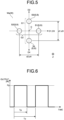
- FIG. 5 is a plan view illustrating an example of a pattern of a plurality of spots S applied to a case where the scanning is performed with the laser light L along the scanning path Pt1 of FIG. 4 to cut the workpiece W.
- FIG. 5 illustrates a shape and arrangement at a moment when the front surface Wa is irradiated with the plurality of beams B of the laser light L and the plurality of spots S is formed.
- the widths d2 and d4 of the entire spot in the state of being scanned in the scanning directions D2 and D4 are distances between the centers of the spots S1 and S2 located at both ends in the directions (In the example of FIG. 5 , the scanning directions D1 and D3) orthogonal to the scanning directions D2 and D4.
- a diameter of each of the spots S is defined as a length of a region where the intensity is 1/e 2 or higher of the peak intensity.
- the irradiation energy E [J/mm] is energy of irradiation per unit length of the front surface Wa, and can be expressed by the following Expression (1) by the experimental research of the inventors.
- E Pp ⁇ Dr / 100 ⁇ v
- L1 represents a length of the irradiation region in a scanning direction
- L2 represents a length of an overlapping region of the pulse and the next pulse in a scanning direction in a case where the pulse and the next pulse overlap in the scanning direction.
- the length of the overlapping region in the scanning direction is defined as 0 in a case where the pulse and the next pulse are in contact in the scanning direction, and -I in a case where the pulse and the next pulse are separated from each other by a distance I (> 0) in the scanning direction.
- the width of the spots S is more preferably 14 [ ⁇ m] or larger and 30 [ ⁇ m] or smaller.
- the widths d1 to d4 of the spots S are preferably 60 [ ⁇ m] or larger and 150 [ ⁇ m] or smaller.
- a distance between the centers of gravity C of the plurality of spots S and a center of a surrounding spot S is preferably 30 [ ⁇ m] or larger and 75 [ ⁇ m] or smaller. It has been found that, in a case where the distance is larger than 75 [ ⁇ m], the thermal effect on a region around a cutting position increases, the desired quality cannot be satisfied, and it is difficult to cut the workpiece W.
- the distance was 75 [ ⁇ m] or smaller, it was possible to decrease the thermal effect on the surrounding region, and it was possible to efficiently perform the cutting. This is presumed to be because, by setting the distance to 75 [ ⁇ m] or smaller, heat applied to the workpiece W at the plurality of separated spots S is appropriately superimposed near the center of gravity C. In addition, in a case where the distance is smaller than 30 [ ⁇ m], it is not possible to obtain the effect of setting the plurality of spots separated in the scanning direction.
- the inventors have observed that, in such laser cutting of the metal foil 10, by intermittently (sporadically) irradiating the front surface Wa with the laser light L at a predetermined frequency, higher-quality processing can be performed in a shorter processing time. From such a viewpoint, the inventors have experimentally found that the frequency of the pulse of the laser light L is preferably 10 [MHz] or lower.
- FIG. 6 is a graph illustrating a schematic temporal change of a pulse of laser light output from the laser device 110.
- the horizontal axis represents time
- the vertical axis represents an output of the laser light from the laser device 110.
- Pp represents a peak power (high power).
- the frequency of the pulse is 1/Tc.
- FIG. 7 is a plan view of the metal foil 10, the plan view including a scanning path Pt2 of a spot of laser light.
- a zone P5 in which the scanning is performed in a scanning direction D5 is interposed between the zone P1 and the zone P2
- a zone P6 in which the scanning is performed in the scanning direction D6 is interposed between the zone P4 and the zone P1.
- the scanning direction D5 is a direction between the scanning direction D1 (D3) and the scanning direction D2
- the scanning direction D6 is a direction between the scanning direction D1 (D3) and the scanning direction D4.
- the scanning path Pt2 is the same as the scanning path Pt1 except that the zones P5 and P6 are interposed and the length of the zone P1 is different.
- the scanning path Pt2 includes four zones (P1 (P3), P5, P2, P6, and the like) in which the scanning is performed in the scanning directions (D1 (D3), D5, D2, D6, and the like) intersecting each other.
- an absolute value (minimum value) of an angle difference between the scanning direction D1 and the scanning directions D5 and D6 is, for example, 45°, but is not limited thereto.
- the scanning directions intersecting each other do not include scanning directions parallel to each other or scanning directions antiparallel to each other (opposite directions).
- the scanning path may include three or five or more zones in which the scanning is performed in scanning directions orthogonal to each other.
- FIG. 8 is a plan view illustrating an example of a pattern of a plurality of spots S applied to a case where the scanning is performed with the laser light L along the scanning path Pt2 of FIG. 7 to cut the workpiece W.
- FIG. 8 also illustrates a shape and arrangement at a moment when the front surface Wa is irradiated with the plurality of beams B of the laser light L and the plurality of spots S is formed.
- the arrangement of the spots S in FIG. 8 is the same as the arrangement of the spots S in FIG. 5 . That is, the plurality of spots S includes the spot groups G1 and G2 (not illustrated in FIG. 8 ) illustrated in FIG. 5 . Further, as illustrated in FIG. 8 , the plurality of spots S includes a spot group G5 including two spots S separated in a scanning direction D5 of a zone P5, and a spot group G6 including two spots S separated in a scanning direction D6 of a zone P6.
- the spot S3 and the spot S2 constitute the spot group G5, and the spot S1 and the spot S4 constitute the spot group G5.
- the two spots S (S3 and S2, and S1 and S4) separated from each other in the scanning direction D5 are irradiated at time intervals at respective positions in the zone P5.
- the spot S1 and the spot S3 constitute the spot group G6, and the spot S4 and the spot S2 constitute the spot group G6.
- the two spots S (S1 and S3, and S4 and S2) separated from each other in the scanning direction D6 are irradiated at time intervals at respective positions in the zone P6.
- the power of the beams B is set such that the workpiece W cannot be cut by the scanning with the individual one beam B, and the workpiece W can be cut by the scanning with the plurality of beams B forming the spot groups G1 to G6.
- FIG. 5 can be applied to, for example, a scanning path including a predetermined zone in a predetermined scanning direction at an angle of 45° as an absolute value (minimum value) of an angle difference with respect to the predetermined zone, and a zone in a scanning direction at an angle of 90° as an absolute value (minimum value) of an angle difference with respect to the predetermined zone. That is, the pattern of FIG. 8 ( FIG. 5 ) is easily applied to the typical shape of the edge 10a.
- FIG. 9 is a plan view illustrating an example of a pattern of a plurality of spots S applied to a case where the scanning is performed with the laser light L along the scanning path Pt1 of FIG. 4 to cut the workpiece W, the example being different from that of FIG. 5 ( FIG. 8 ).
- FIG. 9 also illustrates a shape and arrangement at a moment when the front surface Wa is irradiated with the plurality of beams B of the laser light L and the plurality of spots S is formed.
- a spot S5 positioned at the center of the plurality of spots S is added to the pattern of FIG. 5 .
- the number of spots S increases from two to three in both the spot groups G1 and G2.
- the power of the beams B is set such that the workpiece W cannot be cut by the scanning with the individual one beam B, and the workpiece W can be cut by the scanning with the plurality of beams B forming the spot groups G1 and G2.
- the power of the beam B per irradiation of each position that is, the amount of energy supplied per unit time to each position by performing irradiation once, can be set to be much smaller. Therefore, according to the pattern of FIG. 9 , for example, since an excessive temperature rise at each position can be further curbed, it is possible to further curb occurrence of an inconvenient event such as generation of unevenness in the metal foil 10 or local generation of lumps, and to form the much higher-quality edge 10a.
- a position of the center of gravity C (geometric center) of the spots S included in the spot group G1 substantially coincides with a position of the center of gravity C of the spots S included in the spot group G2.
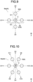
- FIG. 10 is a plan view illustrating another example of the pattern of the plurality of spots S which is different from those of FIGS. 5 , 8 , and 9.
- FIG. 10 also illustrates a shape and arrangement at a moment when the front surface Wa is irradiated with the plurality of beams B of the laser light L and the plurality of spots S is formed.
- the number of spots S is larger than that in FIGS. 5 , 8 , and 9 , and accordingly, the pattern can be applied to a scanning path including zones in which scanning is performed in more scanning directions D1 to D4 and D7 to D11.
- the pattern of FIG. 10 can be applied to a shape of the edge 10a which is more complicated or denser.
- each of the plurality of spot groups includes three spots S, the same effect as that of the pattern of FIG. 9 can be obtained.
- an absolute value (minimum value) of an angle difference between the scanning direction D1 and the scanning directions D8 and D11 is, for example, 60°, but is not limited thereto.
- FIG. 11 is a plan view illustrating another example of the pattern of the plurality of spots S different from those of FIGS. 5 and 8 to 10 .
- FIG. 11 also illustrates a shape and arrangement at a moment when the front surface Wa is irradiated with the plurality of beams B of the laser light L and the plurality of spots S is formed.
- a spot S1 (S) positioned at a substantially center and a plurality of spots S2 disposed side by side in a circumferential shape (annular shape) to surround the spot S1 are arranged on the front surface Wa.
- the plurality of spots S has a larger number of spots S than those in FIGS. 5 and 8 to 10 and has spot groups disposed side by side in various radial directions passing through the center of gravity C
- the present invention can be applied to a scanning path having zones in various scanning directions. That is, the pattern of FIG. 11 can be applied to a shape of the edge 10a which is much more complicated or denser.
- each of the plurality of spot groups includes three spots S, the same effects as those of the patterns of FIGS. 9 and 10 can be obtained.
- the power of the spot S positioned at the center is preferably 50 [%] or higher and 80 [%] or lower with respect to the total value of the power of all the spots S including the center and the periphery. In this case, it has been found that it is preferable to set the center ratio higher as higher power is required to cut the workpiece W.
- the center of the spot S positioned at the center does not necessarily need to coincide with the center of gravity C of the plurality of spots S, and for example, the spot S positioned at the center may be positioned at a position surrounded or sandwiched by the plurality of surrounding spots S, such as being positioned in a polygon having the centers of the surrounding spots S as vertexes.
- FIG. 12 is a plan view illustrating another example of the pattern of the plurality of spots S different from those in FIGS. 5 and 8 to 11 .
- FIG. 12 also illustrates a shape and arrangement at a moment when the front surface Wa is irradiated with the plurality of beams B of the laser light L and the plurality of spots S is formed.
- FIG. 12 illustrates the simplest pattern. Also in this case, positions scanned in the scanning directions D1 and D7 are irradiated with the beams B twice at time intervals. Hence, it is possible to curb occurrence of an inconvenient event such as generation of unevenness in the metal foil 10 or local generation of lumps, and to form the higher-quality edge 10a. Note that the number of linearly aligned spots S may be three or more.
- the plurality of beams of the laser light L is arranged to form the spot groups G1 to G6 including the plurality of spots S separated in the relative scanning directions on the front surface Wa.
- FIG. 13 is a schematic configuration diagram of a laser cutting apparatus 100B (100) of a second embodiment.
- the optical head 120 includes a galvanometer scanner 126 between the collimating lens 121 and the condenser lens 122.
- the galvanometer scanner 126 includes two mirrors 126a and an actuator 126b that changes postures of the mirrors 126a. An irradiation direction and an irradiation position of the laser light L are changed by changing the postures of the two mirrors 126a by the actuator 126b.
- the laser cutting apparatus 100B does not move the optical head 120, but can move, that is, scan, an irradiation position with the beams B of the laser light L, that is, the positions of the spots S, on the front surface Wa.
- the galvanometer scanner 126 may be provided in the optical head 120 of the laser cutting apparatus 100A of the first embodiment. That is, the scanning with the beams B (spots S) of the laser light L on the front surface Wa may be realized by a combination of at least one of the movement of the optical head 120 and the movement of the workpiece W and a change in the emission angle of the laser light L with respect to the optical head 120.
- the number, arrangement, scanning direction (arrangement direction of spots), and the like of the spots (spot group) can be variously modified.
- the scanning path can be variously modified.
Landscapes
- Physics & Mathematics (AREA)
- Optics & Photonics (AREA)
- Engineering & Computer Science (AREA)
- Plasma & Fusion (AREA)
- Mechanical Engineering (AREA)
- Laser Beam Processing (AREA)
Applications Claiming Priority (2)
| Application Number | Priority Date | Filing Date | Title |
|---|---|---|---|
| JP2022058110 | 2022-03-31 | ||
| PCT/JP2023/012611 WO2023190563A1 (ja) | 2022-03-31 | 2023-03-28 | レーザ切断方法およびレーザ切断装置 |
Publications (2)
| Publication Number | Publication Date |
|---|---|
| EP4501522A1 true EP4501522A1 (de) | 2025-02-05 |
| EP4501522A4 EP4501522A4 (de) | 2026-03-25 |
Family
ID=88201807
Family Applications (1)
| Application Number | Title | Priority Date | Filing Date |
|---|---|---|---|
| EP23780572.6A Pending EP4501522A4 (de) | 2022-03-31 | 2023-03-28 | Laserschneidverfahren und laserschneidvorrichtung |
Country Status (6)
| Country | Link |
|---|---|
| US (1) | US20250001526A1 (de) |
| EP (1) | EP4501522A4 (de) |
| JP (1) | JP7688228B2 (de) |
| KR (1) | KR20240144407A (de) |
| CN (1) | CN118804813A (de) |
| WO (1) | WO2023190563A1 (de) |
Families Citing this family (1)
| Publication number | Priority date | Publication date | Assignee | Title |
|---|---|---|---|---|
| WO2021192801A1 (ja) * | 2020-03-24 | 2021-09-30 | 住友重機械工業株式会社 | プロセスモニタ及びプロセスモニタ方法 |
Family Cites Families (3)
| Publication number | Priority date | Publication date | Assignee | Title |
|---|---|---|---|---|
| JP2015188908A (ja) | 2014-03-28 | 2015-11-02 | 株式会社豊田自動織機 | 切断装置及び電極の製造方法 |
| JP2021191588A (ja) * | 2020-06-04 | 2021-12-16 | 古河電気工業株式会社 | レーザ切断方法およびレーザ切断装置 |
| JP7282270B2 (ja) * | 2020-06-30 | 2023-05-26 | 古河電気工業株式会社 | 金属箔のレーザ切断方法およびレーザ切断装置 |
-
2023
- 2023-03-28 WO PCT/JP2023/012611 patent/WO2023190563A1/ja not_active Ceased
- 2023-03-28 EP EP23780572.6A patent/EP4501522A4/de active Pending
- 2023-03-28 KR KR1020247030381A patent/KR20240144407A/ko active Pending
- 2023-03-28 JP JP2024512595A patent/JP7688228B2/ja active Active
- 2023-03-28 CN CN202380027759.6A patent/CN118804813A/zh active Pending
-
2024
- 2024-09-16 US US18/885,803 patent/US20250001526A1/en active Pending
Also Published As
| Publication number | Publication date |
|---|---|
| KR20240144407A (ko) | 2024-10-02 |
| US20250001526A1 (en) | 2025-01-02 |
| WO2023190563A1 (ja) | 2023-10-05 |
| CN118804813A (zh) | 2024-10-18 |
| EP4501522A4 (de) | 2026-03-25 |
| JP7688228B2 (ja) | 2025-06-03 |
| JPWO2023190563A1 (de) | 2023-10-05 |
Similar Documents
| Publication | Publication Date | Title |
|---|---|---|
| JP6108178B2 (ja) | レーザー溶接装置およびレーザー溶接方法 | |
| JP7640264B2 (ja) | 溶接方法および溶接装置 | |
| KR101862298B1 (ko) | 레이저 방사 수단에 의한 재료 가공 장치 | |
| US20210031301A1 (en) | Welding method and welding apparatus | |
| CN112368104A (zh) | 焊接方法以及焊接装置 | |
| US20250001526A1 (en) | Laser cutting method and laser cutting apparatus | |
| JP2008012916A (ja) | 複合シート、複合シートの加工方法、及びレーザ加工装置 | |
| US20120048837A1 (en) | Laser welding system and method for welding by means of a laser beam | |
| EP3323179A1 (de) | Anwendungen, verfahren und systeme für ein adressierbares array mit laserausgabe | |
| US12076816B2 (en) | Laser scanner and laser machining device | |
| KR102198779B1 (ko) | 선형 세기 분포를 갖는 레이저 방사선의 생성 장치 | |
| JP6468175B2 (ja) | 密閉型容器の製造方法 | |
| KR102581115B1 (ko) | 에나멜선 탈피를 위한 레이저 가공 헤드 | |
| WO2020241275A1 (ja) | 加工方法および加工装置 | |
| JPWO2024053744A5 (de) | ||
| KR20250065922A (ko) | 금속 포일의 레이저 절단 방법 | |
| JP7246922B2 (ja) | 溶接装置 | |
| CN113825588B (zh) | 槽加工装置以及槽加工方法 | |
| WO2020241276A1 (ja) | 加工方法および加工装置 | |
| JP5420172B2 (ja) | レーザ装置 | |
| JP7704641B2 (ja) | 金属箔のレーザ切断方法 | |
| JP6043179B2 (ja) | 樹脂被覆除去システム | |
| JP2023009331A (ja) | レーザ走査装置及びレーザ走査方法 |
Legal Events
| Date | Code | Title | Description |
|---|---|---|---|
| STAA | Information on the status of an ep patent application or granted ep patent |
Free format text: STATUS: THE INTERNATIONAL PUBLICATION HAS BEEN MADE |
|
| PUAI | Public reference made under article 153(3) epc to a published international application that has entered the european phase |
Free format text: ORIGINAL CODE: 0009012 |
|
| STAA | Information on the status of an ep patent application or granted ep patent |
Free format text: STATUS: REQUEST FOR EXAMINATION WAS MADE |
|
| 17P | Request for examination filed |
Effective date: 20240923 |
|
| AK | Designated contracting states |
Kind code of ref document: A1 Designated state(s): AL AT BE BG CH CY CZ DE DK EE ES FI FR GB GR HR HU IE IS IT LI LT LU LV MC ME MK MT NL NO PL PT RO RS SE SI SK SM TR |
|
| DAV | Request for validation of the european patent (deleted) | ||
| DAX | Request for extension of the european patent (deleted) | ||
| A4 | Supplementary search report drawn up and despatched |
Effective date: 20260220 |
|
| RIC1 | Information provided on ipc code assigned before grant |
Ipc: B23K 26/064 20140101AFI20260216BHEP Ipc: B23K 26/067 20060101ALI20260216BHEP Ipc: B23K 26/082 20140101ALI20260216BHEP Ipc: B23K 26/38 20140101ALI20260216BHEP Ipc: B23K 26/06 20140101ALI20260216BHEP |