EP4495408A1 - Wasserstoffmotor - Google Patents
Wasserstoffmotor Download PDFInfo
- Publication number
- EP4495408A1 EP4495408A1 EP23796130.5A EP23796130A EP4495408A1 EP 4495408 A1 EP4495408 A1 EP 4495408A1 EP 23796130 A EP23796130 A EP 23796130A EP 4495408 A1 EP4495408 A1 EP 4495408A1
- Authority
- EP
- European Patent Office
- Prior art keywords
- valve
- fuel supply
- intake
- supply valve
- port
- Prior art date
- Legal status (The legal status is an assumption and is not a legal conclusion. Google has not performed a legal analysis and makes no representation as to the accuracy of the status listed.)
- Pending
Links
Images


Classifications
-
- F—MECHANICAL ENGINEERING; LIGHTING; HEATING; WEAPONS; BLASTING
- F02—COMBUSTION ENGINES; HOT-GAS OR COMBUSTION-PRODUCT ENGINE PLANTS
- F02B—INTERNAL-COMBUSTION PISTON ENGINES; COMBUSTION ENGINES IN GENERAL
- F02B43/00—Engines characterised by operating on gaseous fuels; Plants including such engines
- F02B43/02—Engines characterised by means for increasing operating efficiency
- F02B43/04—Engines characterised by means for increasing operating efficiency for improving efficiency of combustion
-
- F—MECHANICAL ENGINEERING; LIGHTING; HEATING; WEAPONS; BLASTING
- F01—MACHINES OR ENGINES IN GENERAL; ENGINE PLANTS IN GENERAL; STEAM ENGINES
- F01L—CYCLICALLY OPERATING VALVES FOR MACHINES OR ENGINES
- F01L1/00—Valve-gear or valve arrangements, e.g. lift-valve gear
- F01L1/12—Transmitting gear between valve drive and valve
- F01L1/14—Tappets; Push rods
- F01L1/146—Push-rods
-
- F—MECHANICAL ENGINEERING; LIGHTING; HEATING; WEAPONS; BLASTING
- F01—MACHINES OR ENGINES IN GENERAL; ENGINE PLANTS IN GENERAL; STEAM ENGINES
- F01L—CYCLICALLY OPERATING VALVES FOR MACHINES OR ENGINES
- F01L1/00—Valve-gear or valve arrangements, e.g. lift-valve gear
- F01L1/12—Transmitting gear between valve drive and valve
- F01L1/18—Rocking arms or levers
- F01L1/181—Centre pivot rocking arms
-
- F—MECHANICAL ENGINEERING; LIGHTING; HEATING; WEAPONS; BLASTING
- F01—MACHINES OR ENGINES IN GENERAL; ENGINE PLANTS IN GENERAL; STEAM ENGINES
- F01L—CYCLICALLY OPERATING VALVES FOR MACHINES OR ENGINES
- F01L3/00—Lift-valve, i.e. cut-off apparatus with closure members having at least a component of their opening and closing motion perpendicular to the closing faces; Parts or accessories thereof
- F01L3/20—Shapes or constructions of valve members, not provided for in preceding subgroups of this group
-
- F—MECHANICAL ENGINEERING; LIGHTING; HEATING; WEAPONS; BLASTING
- F02—COMBUSTION ENGINES; HOT-GAS OR COMBUSTION-PRODUCT ENGINE PLANTS
- F02B—INTERNAL-COMBUSTION PISTON ENGINES; COMBUSTION ENGINES IN GENERAL
- F02B1/00—Engines characterised by fuel-air mixture compression
- F02B1/02—Engines characterised by fuel-air mixture compression with positive ignition
- F02B1/08—Engines characterised by fuel-air mixture compression with positive ignition with separate admission of air and fuel into cylinder
-
- F—MECHANICAL ENGINEERING; LIGHTING; HEATING; WEAPONS; BLASTING
- F02—COMBUSTION ENGINES; HOT-GAS OR COMBUSTION-PRODUCT ENGINE PLANTS
- F02D—CONTROLLING COMBUSTION ENGINES
- F02D19/00—Controlling engines characterised by their use of non-liquid fuels, pluralities of fuels, or non-fuel substances added to the combustible mixtures
- F02D19/02—Controlling engines characterised by their use of non-liquid fuels, pluralities of fuels, or non-fuel substances added to the combustible mixtures peculiar to engines working with gaseous fuels
- F02D19/021—Control of components of the fuel supply system
- F02D19/023—Control of components of the fuel supply system to adjust the fuel mass or volume flow
- F02D19/024—Control of components of the fuel supply system to adjust the fuel mass or volume flow by controlling fuel injectors
-
- F—MECHANICAL ENGINEERING; LIGHTING; HEATING; WEAPONS; BLASTING
- F02—COMBUSTION ENGINES; HOT-GAS OR COMBUSTION-PRODUCT ENGINE PLANTS
- F02D—CONTROLLING COMBUSTION ENGINES
- F02D41/00—Electrical control of supply of combustible mixture or its constituents
- F02D41/30—Controlling fuel injection
- F02D41/38—Controlling fuel injection of the high pressure type
- F02D41/40—Controlling fuel injection of the high pressure type with means for controlling injection timing or duration
- F02D41/401—Controlling injection timing
-
- F—MECHANICAL ENGINEERING; LIGHTING; HEATING; WEAPONS; BLASTING
- F02—COMBUSTION ENGINES; HOT-GAS OR COMBUSTION-PRODUCT ENGINE PLANTS
- F02M—SUPPLYING COMBUSTION ENGINES IN GENERAL WITH COMBUSTIBLE MIXTURES OR CONSTITUENTS THEREOF
- F02M21/00—Apparatus for supplying engines with non-liquid fuels, e.g. gaseous fuels stored in liquid form
- F02M21/02—Apparatus for supplying engines with non-liquid fuels, e.g. gaseous fuels stored in liquid form for gaseous fuels
- F02M21/0203—Apparatus for supplying engines with non-liquid fuels, e.g. gaseous fuels stored in liquid form for gaseous fuels characterised by the type of gaseous fuel
- F02M21/0206—Non-hydrocarbon fuels, e.g. hydrogen, ammonia or carbon monoxide
-
- F—MECHANICAL ENGINEERING; LIGHTING; HEATING; WEAPONS; BLASTING
- F02—COMBUSTION ENGINES; HOT-GAS OR COMBUSTION-PRODUCT ENGINE PLANTS
- F02M—SUPPLYING COMBUSTION ENGINES IN GENERAL WITH COMBUSTIBLE MIXTURES OR CONSTITUENTS THEREOF
- F02M21/00—Apparatus for supplying engines with non-liquid fuels, e.g. gaseous fuels stored in liquid form
- F02M21/02—Apparatus for supplying engines with non-liquid fuels, e.g. gaseous fuels stored in liquid form for gaseous fuels
- F02M21/0218—Details on the gaseous fuel supply system, e.g. tanks, valves, pipes, pumps, rails, injectors or mixers
- F02M21/023—Valves; Pressure or flow regulators in the fuel supply or return system
- F02M21/0233—Details of actuators therefor
-
- F—MECHANICAL ENGINEERING; LIGHTING; HEATING; WEAPONS; BLASTING
- F01—MACHINES OR ENGINES IN GENERAL; ENGINE PLANTS IN GENERAL; STEAM ENGINES
- F01L—CYCLICALLY OPERATING VALVES FOR MACHINES OR ENGINES
- F01L2820/00—Details on specific features characterising valve gear arrangements
- F01L2820/02—Formulas
-
- F—MECHANICAL ENGINEERING; LIGHTING; HEATING; WEAPONS; BLASTING
- F02—COMBUSTION ENGINES; HOT-GAS OR COMBUSTION-PRODUCT ENGINE PLANTS
- F02B—INTERNAL-COMBUSTION PISTON ENGINES; COMBUSTION ENGINES IN GENERAL
- F02B2201/00—Fuels
- F02B2201/04—Gas
-
- F—MECHANICAL ENGINEERING; LIGHTING; HEATING; WEAPONS; BLASTING
- F02—COMBUSTION ENGINES; HOT-GAS OR COMBUSTION-PRODUCT ENGINE PLANTS
- F02B—INTERNAL-COMBUSTION PISTON ENGINES; COMBUSTION ENGINES IN GENERAL
- F02B2275/00—Other engines, components or details, not provided for in other groups of this subclass
- F02B2275/14—Direct injection into combustion chamber
-
- Y—GENERAL TAGGING OF NEW TECHNOLOGICAL DEVELOPMENTS; GENERAL TAGGING OF CROSS-SECTIONAL TECHNOLOGIES SPANNING OVER SEVERAL SECTIONS OF THE IPC; TECHNICAL SUBJECTS COVERED BY FORMER USPC CROSS-REFERENCE ART COLLECTIONS [XRACs] AND DIGESTS
- Y02—TECHNOLOGIES OR APPLICATIONS FOR MITIGATION OR ADAPTATION AGAINST CLIMATE CHANGE
- Y02T—CLIMATE CHANGE MITIGATION TECHNOLOGIES RELATED TO TRANSPORTATION
- Y02T10/00—Road transport of goods or passengers
- Y02T10/10—Internal combustion engine [ICE] based vehicles
- Y02T10/30—Use of alternative fuels, e.g. biofuels
Definitions
- the present disclosure relates to a hydrogen engine.
- Patent Document 1 discloses a hydrogen engine that uses hydrogen fuel.
- an injector for injecting the hydrogen fuel into an intake port is provided, and intake air flowing in the intake port and the hydrogen fuel injected from the injector are mixed and supplied to a combustion chamber.
- Patent Document 1 JP2016-118109A
- an object of at least one embodiment of the present disclosure is to provide a hydrogen engine that can suppress the occurrence of the backfire and can achieve high engine efficiency.
- a hydrogen engine is a hydrogen engine using fuel gas containing hydrogen, including: a cylinder; a piston movable within the cylinder; a cylinder head forming a combustion chamber with the piston, and including an intake port connected to the combustion chamber and a fuel supply port connected to the combustion chamber; an intake valve for opening and closing the intake port; a fuel supply valve for opening and closing the fuel supply port; and a valve train commonly provided for the intake valve and the fuel supply valve, and configured to open and close the intake valve and the fuel supply valve in conjunction with each other.
- the hydrogen engine is configured such that a valve opening timing of the fuel supply valve is more retarded than a valve opening timing of the intake valve.
- a hydrogen engine is a hydrogen engine using fuel gas containing hydrogen, including: a cylinder; a piston movable within the cylinder; a cylinder head forming a combustion chamber with the piston, and including an intake port connected to the combustion chamber, a fuel supply port connected to the combustion chamber, and an exhaust port connected to the combustion chamber; an intake valve for opening and closing the intake port; a fuel supply valve for opening and closing the fuel supply port; a valve train commonly provided for the intake valve and the fuel supply valve, and configured to open and close the intake valve and the fuel supply valve in conjunction with each other; and a cover portion configured to cover at least a part of an outlet portion of the fuel supply port on a side of the exhaust port in at least a part of a valve opening period of the fuel supply valve.
- a hydrogen engine is a hydrogen engine using fuel gas containing hydrogen, including: a cylinder; a piston movable within the cylinder; a cylinder head forming a combustion chamber with the piston, and including an intake port connected to the combustion chamber, a fuel supply port connected to the combustion chamber, and an exhaust port connected to the combustion chamber; an intake valve for opening and closing the intake port; a fuel supply valve for opening and closing the fuel supply port; and a valve train commonly provided for the intake valve and the fuel supply valve, and configured to open and close the intake valve and the fuel supply valve in conjunction with each other.
- a lower surface of the cylinder head is formed along a plane.
- a lower surface of the fuel supply valve is located upstream of a flow of the fuel gas in an axial direction of the fuel supply valve relative to the lower surface of the cylinder head, in a state in which the fuel supply valve abuts against a valve seat surface disposed in the fuel supply port.
- a hydrogen engine which can suppress the occurrence of backfire and can achieve high engine efficiency.
- an expression of relative or absolute arrangement such as “in a direction”, “along a direction”, “parallel”, “orthogonal”, “centered”, “concentric” and “coaxial” shall not be construed as indicating only the arrangement in a strict literal sense, but also includes a state where the arrangement is relatively displaced by a tolerance, or by an angle or a distance whereby it is possible to achieve the same function.
- an expression of an equal state such as “same”, “equal”, and “uniform” shall not be construed as indicating only the state in which the feature is strictly equal, but also includes a state in which there is a tolerance or a difference that can still achieve the same function.
- an expression of a shape such as a rectangular shape or a tubular shape shall not be construed as only the geometrically strict shape, but also includes a shape with unevenness or chamfered corners within the range in which the same effect can be achieved.
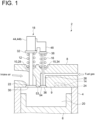
- FIG. 1 is a schematic cross-sectional view of a hydrogen engine 2 according to an embodiment.
- the hydrogen engine 2 will be described taking as an example a four-stroke engine that uses fuel gas containing hydrogen.
- the hydrogen concentration of the fuel gas used by the hydrogen engine 2 may be, for example, at least 50%, at least 75%, or at least 99%.
- the piston 6 is configured to be movable within the cylinder 4.
- the piston 6 reciprocates within the cylinder 4 such that an outer peripheral surface of the piston 6 slides on an inner peripheral surface of the cylinder 4, and a crankshaft (not shown) connected to the piston 6 rotates in conjunction with the reciprocation of the piston 6.
- the cylinder head 8 forms a combustion chamber 20 with the piston 6.
- the cylinder head 8 includes an intake port 22 connected to the combustion chamber 20, an exhaust port 24 connected to the combustion chamber 20, and a fuel supply port 26 connected to the combustion chamber 20.
- a lower surface 9 of the cylinder head 8 is formed along a plane orthogonal to the axial direction of the piston 6.
- the intake valve 10 is configured to open and close the intake port 22.
- the intake valve 10 includes a valve stem 28, a valve body portion 30 disposed on one end side of the valve stem 28, and a force receiving portion 32 disposed on another end side of the valve stem 28.
- the valve stem 28 extends in an up-down direction
- the valve body portion 30 is disposed at a lower end of the valve stem 28
- the force receiving portion 32 is disposed at an upper end of the valve stem 28.
- the valve body portion 30 is formed in a truncated cone shape such that an outer diameter of the valve body portion 30 decreases toward an upstream side of an intake air flow, and an inclined surface (an inclined surface inclined with respect to the axial direction of the intake valve 10) of the truncated cone shape is disposed to be abuttable against a valve seat surface of the intake port 22 in the axial direction of the intake valve 10 (the axial direction of the valve stem 28).
- the force receiving portion 32 is formed in a plate shape along the plane orthogonal to the axial direction of the intake valve 10.
- the valve spring 12 is interposed in a compressed state between an upper surface of the cylinder head 8 and a lower surface of the force receiving portion 32, and biases the force receiving portion 32 upward to bias the intake valve 10 in a closing direction.
- the exhaust valve 14 is configured to open and close the exhaust port 24.
- the exhaust valve 14 has a structure similar to that of the intake valve 10, and a valve spring (not shown) biases the exhaust valve 14 in a closing direction.
- the intake cam 41 is formed integrally with the intake camshaft 40 in the intake camshaft 40.
- the intake camshaft 40 rotates together with the intake cam 41 in conjunction with a rotation of a crankshaft (not shown) of the hydrogen engine 2.
- a lower end portion of the push rod 42 abuts against an outer peripheral surface (cam surface) of the intake cam 41, and as the intake cam 41 rotates, a distance r between the push rod 42 and a rotational axis C1 of the intake cam 41 changes, causing the push rod 42 to reciprocate in the axial direction of the push rod 42.
- the fuel supply valve arm 48 is connected to an another end portion 44b side of the intake rocker arm 44, and rotates around the rotational axis C2 together with the intake rocker arm 44. Since the fuel supply valve arm 48 rotates around the rotational axis C2, a tip portion 48a of the fuel supply valve arm 48 can press the fuel supply valve 15.
- the rotation of the intake rocker arm 44 causes the tip portion 48a of the fuel supply valve arm 48 to push the fuel supply valve 15 down against a biasing force of the valve spring 16 (see FIG. 1 ), causing the fuel supply valve 15 to move in the open direction. Further, the rotation of the intake rocker arm 44 displaces the tip portion 48a of the fuel supply valve arm 48 in a direction of the biasing force of the valve spring 16, causing the fuel supply valve 15 to move in the closing direction.
- FIG. 3 is an enlarged view showing an example of the configuration in the vicinity of the another end portion 44b of the intake rocker arm 44 shown in FIGs. 1 and 2 .
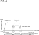
- FIG. 4 is a chart showing an example of changes in respective effective opening areas of the intake valve 10, the exhaust valve 14, and the fuel supply valve 15 in one combustion cycle of the hydrogen engine 2.
- a maximum value glmax of the distance g1 in the one combustion cycle of the hydrogen engine 2 may be greater than a maximum value g2max of the distance g2 in the one combustion cycle of the hydrogen engine 2.
- the distance g1 between the fuel supply valve arm 48 and the fuel supply valve 15 and the distance g2 between the intake rocker arm 44 and the intake valve 10 are at the maximum value glmax and the maximum value g2max, respectively (that is, the intake valve 10 and the fuel supply valve 15 are at their valve closing positions, respectively), and the maximum value glmax is greater than the maximum value g2max.
- a valve opening timing FO of the fuel supply valve 15 is more retarded than a valve opening timing IO of the intake valve 10.
- a dotted and dashed line indicates the effective opening area of the exhaust valve 14 (a throat area corresponding to a position of the exhaust valve 14 in the exhaust port 24)
- a solid line indicates the effective opening area of the intake valve 10 (a throat area corresponding to a position of the intake valve 10 in the intake port 22)
- a dashed line indicates the effective opening area of the fuel supply valve 15 (a throat area corresponding to a position of the fuel supply valve 15 in the fuel supply port 26).
- EO indicates a valve opening timing of the exhaust valve 14
- EC indicates a valve closing timing of the exhaust valve 14
- FC indicates a valve closing timing of the fuel supply valve 15
- IC indicates a valve closing timing of the intake valve 10.
- valve opening timing means a timing at which the valve starts to open (a timing at which the effective opening area starts to increase from 0)
- valve closing timing means a timing at which the valve closes (a timing at which the effective opening area becomes 0).
- the distance g1 between the fuel supply valve arm 48 and the fuel supply valve 15 may be greater than 0 at the valve closing timing EC of the exhaust valve 14 in an exhaust stroke of the hydrogen engine 2 (see FIG. 4 ).
- the fuel supply port 26 is disposed separately from the intake port 22, and the fuel gas containing hydrogen is supplied to the combustion chamber 20 from the fuel supply port 26 without via the intake port 22. Therefore, it is possible to suppress the occurrence of backfire in which a flame travels back to the intake port 22.
- the valve opening timing FO of the fuel supply valve 15 can be more retarded than the valve opening timing IO of the intake valve 10. Therefore, even if there is a period of overlap between a valve opening period of the intake valve 10 and a valve opening period of the exhaust valve 14 (a period from the valve opening timing IO of the intake valve 10 to the valve closing timing EC of the exhaust valve 14 in FIG. 4 ), it is possible to suppress discharge of a part of the fuel gas supplied from the fuel supply port 26 to the combustion chamber 20 from the exhaust port 24 without being burned.
- the valve opening timing FO of the fuel supply valve 15 can be more retarded than the valve closing timing EC of the exhaust valve 14. Therefore, it is possible to effectively suppress discharge of a part of the fuel gas supplied from the fuel supply port 26 to the combustion chamber 20 from the exhaust port 24 without being burned.
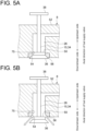
- FIGs. 5A to 5C are views for describing an example of the detailed configuration of the fuel supply valve 15 shown in FIGs. 1 and 2 .
- FIG. 5A shows a state in which the valve body portion 36 of the fuel supply valve 15 abuts against the valve seat surface 54 of the fuel supply port 26 and the fuel supply port 26 is closed.
- FIG. 5B shows a state in which the valve body portion 36 of the fuel supply valve 15 is separated from the valve seat surface 54 of the fuel supply port 26 and the fuel supply port 26 is open.
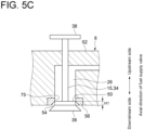
- FIG. 5C shows a state in which the valve body portion 36 of the fuel supply valve 15 is separated from the valve seat surface 54 and the fuel supply port 26 is closed by a collar portion 50 of the fuel supply valve 15 (a state between the state shown in FIG. 5A and the state shown in FIG. 5B ).
- the fuel supply valve 15 includes the collar portion 50 in addition to the valve stem 34, the valve body portion 36, and the force receiving portion 38 which are described above.
- the cylinder head 8 includes a cylinder head body 52, and an annular valve seat member 56 forming the annular valve seat surface 54 of the fuel supply port 26 and configured separately from the cylinder head body 52.
- the collar portion 50 is disposed adjacent to the valve body portion 36 between the valve stem 34 and the valve body portion 36 (an upper end of the valve body portion 36), and is formed in a disk or columnar shape.
- An outer diameter of the collar portion 50 is greater than an outer diameter of the valve stem 34 and approximately coincides with a flow passage width of the fuel supply port 26, that is, an inner diameter of the annular valve seat member 56.
- the outer diameter of the collar portion 50 is set such that an outer peripheral surface of the collar portion 50 can slide on a flow passage wall 75 of the fuel supply port 26 (an inner peripheral surface of the valve seat member 56 in the illustrated examples).
- the collar portion 50 is located upstream of a fuel gas flow in the axial direction of the fuel supply valve 15 relative to the valve seat surface 54.
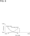
- the collar portion 50 is configured to satisfy H1 >0.7 ⁇ L, where H1 is a height of the collar portion 50 in the axial direction of the fuel supply valve 15 as shown in FIG. 5C and L1 is a lift amount of the fuel supply valve 15 at the valve closing timing EC of the exhaust valve 14 in the exhaust stroke of the hydrogen engine 2 (see FIG. 4 ) as shown in FIG. 6 . Further, more preferably, the collar portion 50 is configured to satisfy H1>L.
- the horizontal axis represents a crank angle of the hydrogen engine 2
- the vertical axis means a lift amount of each of the exhaust valve 14 and the fuel supply valve 15.
- the above-described lift amount L shown in FIG. 6 means a distance between the valve seat surface 54 and the valve body portion 36 of the fuel supply valve 15 at the valve closing timing EC of the exhaust valve 14 in the exhaust stroke of the hydrogen engine 2 (see FIG. 4 ).
- the valve opening timing FO of the fuel supply valve 15 can be more retarded than the valve closing timing EC of the exhaust valve 14. Therefore, it is possible to effectively suppress discharge of a part of the fuel gas supplied from the fuel supply port 26 to the combustion chamber 20 from the exhaust port 24 without being burned.
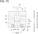
- FIGs. 7A to 7C are views for describing an example of the detailed configuration of the cylinder head 8 shown in FIGs. 1 and 2 .
- FIG. 7A shows the state in which the valve body portion 36 of the fuel supply valve 15 abuts against the valve seat surface 54 of the fuel supply port 26 and the fuel supply port 26 is closed.
- FIG. 7B shows the state in which the valve body portion 36 of the fuel supply valve 15 is separated from the valve seat surface 54 of the fuel supply port 26 and the fuel supply port 26 is open.
- FIG. 7C shows a state in which the valve body portion 36 of the fuel supply valve 15 is separated from the valve seat surface 54 and the valve body portion 36 of the fuel supply valve 15 is in contact with the inner peripheral surface of the valve seat member 56 (a state between the state shown in FIG. 7A and the state shown in FIG. 7B ).
- the fuel supply port 26 includes a first flow passage portion 60 disposed along the axial direction of the fuel supply valve 15, the valve seat surface 54 disposed downstream of the first flow passage portion 60, and a second flow passage portion 62 disposed downstream of the valve seat surface 54 and having a flow passage width W2 greater than a flow passage width W1 of the first flow passage portion 60.
- a step 65 is formed between the valve seat surface 54 and an opening end 63 on an outlet side of the fuel supply port 26.
- An outer diameter D of the valve body portion 36 approximately coincides with the flow passage width W2 of the second flow passage portion 62, and a downstream end edge 55 (maximum outer diameter portion) of the outer peripheral surface 53 (the above-described inclined surface 53) of the valve body portion 36 of the fuel supply valve 15 is configured to slide on a flow passage wall 64 of the second flow passage portion 62.
- the outer diameter D of the valve body portion 36 means a maximum value of the outer diameter of the valve body portion 36, and in the illustrated example means the outer diameter of the valve body portion 36 at a lower end of the valve body portion 36.
- the second flow passage portion 62 is configured to satisfy H2>0.7L, where H2 is a length of the second flow passage portion 62 (a height of the above-described step 65) in the axial direction of the fuel supply valve 15 as shown in FIG. 7C and L is the lift amount of the fuel supply valve 15 at the valve closing timing EC of the exhaust valve 14 in the exhaust stroke of the hydrogen engine 2 as shown in FIG. 6 . Further, more preferably, the second flow passage portion 62 is configured to satisfy H2>L.
- the second flow passage portion 62 having the flow passage width W2 greater than the flow passage width W1 of the first flow passage portion 60 is disposed downstream of the valve seat surface 54, and the outer peripheral surface 53 of the valve body portion 36 is configured to slide on the flow passage wall 64 of the second flow passage portion 62. Therefore, as shown in FIG. 7C , even if the valve body portion 36 is separated from the valve seat surface 54, it is possible to maintain the state in which the fuel supply port 26 is closed or the state in which the opening area of the fuel supply port 26 is small as long as the outer peripheral surface 53 of the valve body portion 36 slides on the flow passage wall 64 of the second flow passage portion 62.
- valve opening timing FO of the fuel supply valve 15 can be more retarded than the valve opening timing IO of the intake valve 10. Therefore, even if there is the period of overlap between the valve opening period of the intake valve 10 and the valve opening period of the exhaust valve 14, it is possible to suppress discharge of a part of the fuel gas supplied from the fuel supply port 26 to the combustion chamber 20 from the exhaust port 24 without being burned. Thus, it is possible to suppress the decrease in engine efficiency, and to implement the highly efficient hydrogen engine 2.
- the valve opening timing FO of the fuel supply valve 15 can be more retarded than the valve closing timing EC of the exhaust valve 14. Therefore, it is possible to effectively suppress discharge of a part of the fuel gas supplied from the fuel supply port 26 to the combustion chamber 20 from the exhaust port 24 without being burned.
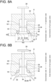
- FIGs. 8A to 8C are views for describing another example of the detailed configuration of the cylinder head 8 shown in FIGs. 1 and 2 .
- FIG. 8A shows the state in which the valve body portion 36 of the fuel supply valve 15 abuts against the valve seat surface 54 of the fuel supply port 26 and the fuel supply port 26 is closed.
- FIG. 8B shows the state in which the valve body portion 36 of the fuel supply valve 15 is separated from the valve seat surface 54 of the fuel supply port 26 and the fuel supply port 26 is open.
- FIG. 8C shows the state in which the valve body portion 36 of the fuel supply valve 15 is separated from the valve seat surface 54 of the fuel supply port 26 and the fuel supply port 26 is open (a state between the state shown in FIG. 8A and the state shown in FIG. 8B ).
- the fuel supply port 26 includes the first flow passage portion 60 disposed along the axial direction of the fuel supply valve 15, the valve seat surface 54 disposed downstream of the first flow passage portion 60, and the second flow passage portion 62 disposed downstream of the valve seat surface 54 and having the flow passage width W2 greater than the flow passage width W1 of the first flow passage portion 60 (see FIG. 8A ).
- the step 65 is formed between the valve seat surface 54 and the opening end 63 on the outlet side of the fuel supply port 26.
- the flow passage width W2 of the second flow passage portion 62 is greater than the outer diameter D of the valve body portion 36 (see FIG. 8A ).
- the outer diameter D of the valve body portion 36 means the maximum value of the outer diameter of the valve body portion 36, and in the illustrated example means the outer diameter of the valve body portion 36 at the lower end of the valve body portion 36.
- the lower surface 66 of the fuel supply valve 15 is located upstream, that is, on an upper side of the fuel gas flow in the axial direction of the fuel supply valve 15 relative to the lower surface 9 of the cylinder head 8.
- the second flow passage portion 62 is configured to satisfy H3>L, where H3 is a distance between the lower surface 66 of the fuel supply valve 15 and the lower surface 9 of the cylinder head 8 in the axial direction of the fuel supply valve 15 in the state in which the fuel supply valve 15 abuts against the valve seat surface 54 disposed in the fuel supply port 26 as shown in FIG. 8A and L is the lift amount of the fuel supply valve 15 at the valve closing timing EC of the exhaust valve 14 in the exhaust stroke of the hydrogen engine 2 as shown in FIG. 6 .
- valve opening timing FO of the fuel supply valve 15 can be more retarded than the valve closing timing EC of the exhaust valve 14. Therefore, it is possible to effectively suppress discharge of a part of the fuel gas supplied from the fuel supply port 26 to the combustion chamber 20 from the exhaust port 24 without being burned.
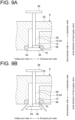
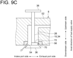
- FIGs. 9A to 9C are views for describing another example of the detailed configuration of the fuel supply valve 15 shown in FIGs. 1 and 2 .
- FIG. 9A shows the state in which the valve body portion 36 of the fuel supply valve 15 abuts against the valve seat surface 54 of the fuel supply port 26 and the fuel supply port 26 is closed.
- FIG. 9B shows the state in which the valve body portion 36 of the fuel supply valve 15 is separated from the valve seat surface 54 of the fuel supply port 26 and the fuel supply port 26 is open.
- FIG. 9A shows the state in which the valve body portion 36 of the fuel supply valve 15 abuts against the valve seat surface 54 of the fuel
- FIG. 9C shows a state in which the valve body portion 36 of the fuel supply valve 15 is separated from the valve seat surface 54 and at least a part of an outlet portion 70 of the fuel supply port 26 on an exhaust port 24 side is covered by the collar portion 72 (cover portion) of the fuel supply valve 15 (a state between the state shown in FIG. 9A and the state shown in FIG. 9B ).
- the collar portion 72 is disposed adjacent to the valve body portion 36 between the valve stem 34 and the valve body portion 36 (the upper end of the valve body portion 36), has a fan shape when viewed in the axial direction of the fuel supply valve 15, and is disposed so as to protrude from the valve stem 34 in the radial direction of the valve stem 34.
- the amount of the protrusion of the collar portion 72 from the valve stem 34 in the radial direction of the valve stem 34 (the length of the chord of the above-described fan shape) may be set such that the outer peripheral surface of the collar portion 72 can slide on the flow passage wall of the fuel supply port 26 (the inner peripheral surface of the valve seat member 56).
- the collar portion 72 is located upstream of the fuel gas flow in the axial direction of the fuel supply valve 15 relative to the valve seat surface 54.
- the collar portion 72 is configured to cover at least a part of the outlet portion 70 of the fuel supply port 26 on the exhaust port 24 side in at least a part of the valve opening period of the fuel supply valve 15.
- a rotation stopper may be provided to prevent the rotation of the fuel supply valve 15.
- the rotation stopper may be implemented by, for example, providing a notch in the valve stem 34 of the fuel supply valve 15 and providing in the cylinder head 8 an engagement portion engaging with the notch.
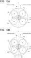
- the collar portion 72 may be disposed in a range S1 on the exhaust port 24 side in the circumferential direction around an axis C3 of the fuel supply valve 15 (the central axis of the valve stem 34).
- a side on which two intake ports 22 are arranged is defined as the intake port 22 side and a side on which two exhaust ports 24 are arranged is defined as the exhaust port 24 side with respect to a plane K including the axis C3 of the fuel supply valve 15.
- the collar portion 72 may be disposed in a range of not less than 180°, which includes the range S1 on the exhaust port 24 side, in the circumferential direction around the axis C3 of the fuel supply valve 15.
- the collar portion 72 is disposed over the range S1 on the exhaust port 24 side and the range S2 adjacent to an upstream side of the range S1 in a swirl direction of a swirling flow of intake air flowing into the combustion chamber 20 from the intake ports 22, in the circumferential direction around the axis of the fuel supply valve 15.
- an angular width OL is a width of the crank angle, which corresponds to, of one combustion cycle of the hydrogen engine 2, the period of overlap between the valve opening period of the exhaust valve 14 and the valve opening period of the fuel supply valve 15 (a width of the crank angle from the valve opening timing FO of the fuel supply valve 15 to the valve closing timing EC of the exhaust valve 14 in FIG.
- the collar portion 72 may be configured in a range including, in the circumferential direction around the axis C3 of the fuel supply valve 15, the range S1 on the exhaust port 24 side and the range S2 of the angle ⁇ from an upstream end in a rotational direction of the swirling flow in the range S1 to the upstream side in the rotational direction of the swirling flow.
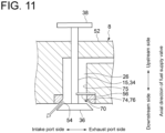
- FIG. 11 is a view for describing yet another example of the detailed configuration of the cylinder head 8 shown in FIGs. 1 and 2 .
- the cylinder head 8 includes the cylinder head body 52, the annular valve seat member 56 forming the valve seat surface 54 of the fuel supply port 26 and configured separately from the cylinder head body 52, and a mask plate 74 located between the cylinder head body 52 and the valve seat member 56 in the axial direction of the fuel supply valve 15.
- the mask plate 74 is located upstream of the fuel gas flow relative to the valve seat member 56 in the axial direction of the fuel supply valve 15, and is interposed between the cylinder head body 52 and the valve seat member 56.
- the mask plate 74 has a fan shape when viewed in the axial direction of the fuel supply valve 15, and includes a protruding portion 76 (cover portion) protruding from the flow passage wall 75 of the fuel supply port 26 toward the valve stem 34.
- the amount of the protrusion of the mask plate 74 from the flow passage wall 75 in the radial direction of the valve stem 34 may be set to a protrusion amount that allows an inner peripheral edge of the mask plate 74 to slide on the outer peripheral surface of the valve stem 34.
- the protruding portion 76 of the mask plate 74 is configured to cover at least a part of the outlet portion 70 of the fuel supply port 26 on the exhaust port 24 side. Whereby, since the fuel gas is less likely to flow from the fuel supply port 26 to the exhaust port 24 side, it is possible to suppress discharge of a part of the fuel gas supplied from the fuel supply port 26 to the combustion chamber 20 from the exhaust port 24 without being burned. Further, compared to the configurations shown in FIGs. 9A to 9C , by reducing the weight of the fuel supply valve 15, it is possible to improve responsiveness of the fuel supply valve 15 and to facilitate manufacture or quality control of the fuel supply valve 15.
- a fuel distribution within the cylinder 4 becomes such that a fuel concentration is high on the intake side and the fuel concentration is low on the exhaust side.
- the intake side burns before the exhaust side, it is possible to suppress knocking (if the fuel concentration is uniform, since the exhaust side having a high temperature burns first and the intake side burns over time, an end gas left on a low-temperature wall surface on the intake side self-ignites finally, causing knocking).
- the protruding portion 76 of the mask plate 74 may be disposed in the range S 1 on the exhaust port 24 side in the circumferential direction around the axis C of the fuel supply valve 15.
- the side on which the two intake ports 22 are arranged is defined as the intake port 22 side and the side on which the two exhaust ports 24 are arranged is defined as the exhaust port 24 side with respect to the plane K including the axis C of the fuel supply valve 15.
- the protruding portion 76 of the mask plate 74 may be disposed in the range of not less than 180°, which includes the range S1 on the exhaust port 24 side, in the circumferential direction around the axis of the fuel supply valve 15.
- the protruding portion 76 of the mask plate 74 is disposed over the range S 1 on the exhaust port 24 side and the range S2 adjacent to the upstream side of the range S 1 in the swirl direction of the swirling flow of the intake air flowing into the combustion chamber from the intake ports, in the circumferential direction around the axis of the fuel supply valve 15.
- the protruding portion 76 of the mask plate 74 may be configured in the range including, in the circumferential direction around the axis C of the fuel supply valve 15, the range S1 on the exhaust port 24 side and the range S2 of the angle ⁇ from the upstream end in the rotational direction of the swirling flow in the range S1 to the upstream side in the rotational direction of the swirling flow.
- FIG. 13 is a view for describing yet another example of the detailed configuration of the cylinder head 8 shown in FIGs. 1 and 2 .
- the annular valve seat member 56 includes a protruding portion 77 (cover portion) protruding from the flow passage wall 75 of the fuel supply port 26 toward the valve stem 34.
- the amount of the protrusion of the valve seat member 56 from the flow passage wall 75 in the radial direction of the valve stem 34 may be set to a protrusion amount that allows the protruding portion 77 of the valve seat member 56 to slide on the outer peripheral surface of the valve stem 34.
- the protruding portion 77 of the valve seat member 56 is configured to cover at least a part of the outlet portion 70 of the fuel supply port 26 on the exhaust port 24 side. Whereby, since the fuel gas is less likely to flow from the fuel supply port 26 to the exhaust port 24 side, it is possible to suppress discharge of a part of the fuel gas supplied from the fuel supply port 26 to the combustion chamber 20 from the exhaust port 24 without being burned. Further, compared to the configurations shown in FIGs. 9A to 9C , by reducing the weight of the fuel supply valve 15, it is possible to improve responsiveness of the fuel supply valve 15 and to facilitate manufacture or quality control of the fuel supply valve 15.
- the fuel gas is less likely to be supplied to the exhaust port 24 side regardless of the lift amount of the fuel supply valve 15, a fuel distribution within the cylinder 4 becomes such that the fuel concentration is high on the intake side and the fuel concentration is low on the exhaust side.
- the intake side burns before the exhaust side, it is possible to suppress knocking (if the fuel concentration is uniform, since the exhaust side having the high temperature burns first and the intake side burns over time, the end gas left on the low-temperature wall surface on the intake side self-ignites finally, causing knocking). Further, the number of parts can be reduced as compared to the configuration shown in FIG. 11 .
- the protruding portion 77 of the valve seat member 56 described above may be disposed in the range S1 on the exhaust port 24 side in the circumferential direction around the axis C of the fuel supply valve 15.
- the side on which the two intake ports 22 are arranged is defined as the intake port 22 side and the side on which the two exhaust ports 24 are arranged is defined as the exhaust port 24 side with respect to the plane K including the axis C of the fuel supply valve 15.
- the protruding portion 77 of the valve seat member 56 may be disposed in the range of not less than 180°, which includes the range S1 on the exhaust port 24 side, in the circumferential direction around the axis of the fuel supply valve 15.
- the protruding portion 77 of the valve seat member 56 is disposed over the range S1 on the exhaust port 24 side and the range S2 adjacent to the upstream side of the range S1 in the swirl direction of the swirling flow of the intake air flowing into the combustion chamber from the intake ports, in the circumferential direction around the axis of the fuel supply valve 15.
- the protruding portion 77 of the valve seat member 56 may be configured in the range including the range S1 on the exhaust port 24 side and the range S2 of the angle ⁇ from the upstream end in the rotational direction of the swirling flow in the range S1 to the upstream side in the rotational direction of the swirling flow.
- the present disclosure is not limited to the above-described embodiments, and also includes an embodiment obtained by modifying the above-described embodiments or an embodiment obtained by combining these embodiments as appropriate.
- the fuel supply port is disposed separately from the intake port, and the fuel gas is supplied to the combustion chamber from the fuel supply port without via the intake port. Therefore, it is possible to suppress the occurrence of backfire in which a flame travels back to the intake port. Further, since the valve opening timing of the fuel supply valve is more retarded than the valve opening timing of the intake valve, even if there is the period of overlap between the valve opening period of the intake valve and the valve opening period of the exhaust valve, it is possible to suppress discharge of a part of the fuel gas supplied from the fuel supply port to the combustion chamber from the exhaust port without being burned. Thus, it is possible to suppress the decrease in engine efficiency, and to implement the highly efficient hydrogen engine. Therefore, it is possible to suppress the occurrence of backfire and to achieve high engine efficiency.
- the valve train includes: an intake rocker arm (such as the above-described intake rocker arm 44) configured to rotate around a predetermined rotational axis (such as the above-described rotational axis C2) and to press the intake valve; and a fuel supply valve arm (such as the above-described fuel supply valve arm 48) configured to rotate around the rotational axis together with the intake rocker arm and to press the fuel supply valve, and a maximum value (such as the above-described maximum value glmax) of a distance between the fuel supply valve arm and the fuel supply valve in one combustion cycle of the engine is greater than a maximum value (such as the above-described maximum value g2max) of a distance between the intake rocker arm and the intake valve in the one combustion cycle of the engine.
- a maximum value such as the above-described maximum value glmax
- the valve opening timing of the fuel supply valve can be more retarded than the valve opening timing of the intake valve. Therefore, with the simple configuration, it is possible to achieve the effect as defined in the above (1).
- the distance (such as the above-described distance g1) between the fuel supply valve arm and the fuel supply valve at a valve closing timing (such as the above-described valve closing timing EC) of an exhaust valve of the engine is greater than 0.
- the valve opening timing of the fuel supply valve can be more retarded than the valve closing timing of the exhaust valve. Therefore, it is possible to effectively suppress discharge of a part of the fuel gas supplied from the fuel supply port to the combustion chamber from the exhaust port without being burned.
- the fuel supply valve includes: a valve stem (such as the above-described valve stem 34); a valve body portion (such as the above-described valve body portion 36) disposed on one end side of the valve stem and abuttable against a valve seat surface of the fuel supply port in an axial direction of the valve stem; and a collar portion (such as the above-described collar portion 50) disposed between the valve stem and the valve body portion, and located upstream of a flow of the fuel gas in an axial direction of the fuel supply valve relative to the valve seat surface of the fuel supply port in a state in which the valve body portion abuts against the valve seat surface.
- a valve stem such as the above-described valve stem 34
- a valve body portion such as the above-described valve body portion 36
- a collar portion such as the above-described collar portion 50
- the valve opening timing of the fuel supply valve can be more retarded than the valve opening timing of the intake valve. Therefore, with the simple configuration, it is possible to achieve the effect as defined in the above (1).
- H1>0.7L is satisfied, where L is a lift amount of the fuel supply valve at a valve closing timing of an exhaust valve of the engine and H1 is a height of the collar portion.
- the valve opening timing of the fuel supply valve can be more retarded than the valve closing timing of the exhaust valve. Therefore, it is possible to effectively suppress discharge of a part of the fuel gas supplied from the fuel supply port to the combustion chamber from the exhaust port without being burned.
- the fuel supply port includes: a first flow passage portion (such as the above-described first flow passage portion 60) disposed along an axial direction of the fuel supply valve; a valve seat surface (such as the above-described valve seat surface 54) disposed downstream of the first flow passage portion; and a second flow passage portion (such as the above-described second flow passage portion 62) disposed downstream of the valve seat surface and having a flow passage width greater than a flow passage width of the first flow passage portion, and an outer peripheral surface of a valve body portion of the fuel supply valve is configured to slide on a flow passage wall (such as the above-described flow passage wall 64) of the second flow passage portion.
- a first flow passage portion such as the above-described first flow passage portion 60
- a valve seat surface such as the above-described valve seat surface 54
- a second flow passage portion such as the above-described second flow passage portion 62
- the valve opening timing of the fuel supply valve can be more retarded than the valve opening timing of the intake valve. Therefore, with the simple configuration, it is possible to achieve the effect as defined in the above (1). Further, since the weight of the fuel supply valve can be reduced compared to the configuration as defined in (4), it is possible to improve responsiveness of the fuel supply valve.
- H2>0.7L is satisfied, where L is a lift amount of the fuel supply valve at a valve closing timing of an exhaust valve of the engine and H2 is a length of the second flow passage portion in an axial direction of the fuel supply valve.
- the valve opening timing of the fuel supply valve can be more retarded than the valve closing timing of the exhaust valve. Therefore, it is possible to effectively suppress discharge of a part of the fuel gas supplied from the fuel supply port to the combustion chamber from the exhaust port without being burned.
- a hydrogen engine is a hydrogen engine (such as the above-described hydrogen engine 2) using fuel gas containing hydrogen, including: a cylinder (such as the above-described cylinder 4); a piston (such as the above-described piston 6) movable within the cylinder; a cylinder head forming a combustion chamber (such as the above-described combustion chamber 20) with the piston, and including an intake port (such as the above-described intake port 22) connected to the combustion chamber, a fuel supply port (such as the above-described fuel supply port 26) connected to the combustion chamber, and an exhaust port (such as the above-described exhaust port 24) connected to the combustion chamber; an intake valve (such as the above-described intake valve 10) for opening and closing the intake port; a fuel supply valve (such as the above-described fuel supply valve 15) for opening and closing the fuel supply port; a valve train (such as the above-described valve train 18) commonly provided for the intake valve and the fuel supply valve, and configured to
- the cover portion since at least a part of the outlet portion of the fuel supply port on the side of the exhaust port is covered by the cover portion in at least a part of the valve opening period of the fuel supply valve, the fuel gas is less likely to flow from the fuel supply valve to the side of the exhaust port. Therefore, it is possible to suppress discharge of a part of the fuel gas supplied from the fuel supply port to the combustion chamber from the exhaust port without being burned.
- the cover portion is a collar portion (such as the above-described collar portion 72) disposed between a valve stem of the fuel supply valve and a valve body portion, and the collar portion is formed in a disk or columnar shape, is located upstream of a flow of the fuel gas in an axial direction of the fuel supply valve relative to a valve seat surface of the fuel supply port in a state in which a valve body portion of the fuel supply valve abuts against the valve seat surface, and has an outer diameter greater than an outer diameter of the valve stem.
- a collar portion such as the above-described collar portion 72
- the fuel gas flow from the fuel supply port to the exhaust port side can be suppressed by the collar portion. Therefore, with the simple configuration, it is possible to achieve the effect as defined in the above (8).
- the cylinder head in the hydrogen engine as defined in the above (8), includes: a cylinder head body (such as the above-described cylinder head body 52); a valve seat member (such as the above-described valve seat member 56) forming a valve seat surface of the fuel supply port and configured separately from the cylinder head body; and a mask plate (such as the above-described mask plate 74) interposed between the cylinder head body and the valve seat member, the mask plate includes a protruding portion (such as the above-described protruding portion 76) protruding from a flow passage wall of the fuel supply port toward a valve stem of the fuel supply valve, and the cover portion is the protruding portion.
- a cylinder head body such as the above-described cylinder head body 52
- a valve seat member such as the above-described valve seat member 56
- a mask plate such as the above-described mask plate 74
- the fuel gas flow from the fuel supply port to the exhaust port side can be suppressed by the protruding portion of the mask plate. Therefore, with the simple configuration, it is possible to achieve the effect as defined in the above (8). Further, compared to the configuration of the above (9), by reducing the weight of the fuel supply valve, it is possible to improve responsiveness of the fuel supply valve and to facilitate manufacture or quality control of the fuel supply valve. Furthermore, since the fuel gas is less likely to be supplied to the exhaust port side regardless of the lift amount of the fuel supply valve, a fuel distribution within the cylinder becomes such that the fuel concentration is high on the intake side and the fuel concentration is low on the exhaust side.
- the cylinder head in the hydrogen engine as defined in the above (8), includes: a cylinder head body (such as the above-described cylinder head body 52); and a valve seat member (such as the above-described valve seat member 56) forming a valve seat surface of the fuel supply port and configured separately from the cylinder head body, the valve seat member includes a protruding portion (such as the above-described protruding portion 77) protruding from a flow passage wall of the fuel supply port toward a valve stem of the fuel supply valve, and the cover portion is the protruding portion.
- a protruding portion such as the above-described protruding portion 77
- the fuel gas flow from the fuel supply port to the exhaust port side can be suppressed by the protruding portion of the valve seat member. Therefore, with the simple configuration, it is possible to achieve the effect as defined in the above (8). Further, compared to the configuration of the above (9), by reducing the weight of the fuel supply valve, it is possible to improve responsiveness of the fuel supply valve and to facilitate manufacture or quality control of the fuel supply valve. Furthermore, since the fuel gas is less likely to be supplied to the exhaust port side regardless of the lift amount of the fuel supply valve, the fuel distribution within the cylinder becomes such that the fuel concentration is high on the intake side and the fuel concentration is low on the exhaust side.
- the intake side burns before the exhaust side, it is possible to suppress knocking (if the fuel concentration is uniform, since the exhaust side having the high temperature burns first and the intake side burns over time, the end gas left on the low-temperature wall surface on the intake side self-ignites finally, causing knocking). Further, the number of parts can be reduced as compared to the above configuration (10).
- an angular width OL is a width of a crank angle, which corresponds to, of one combustion cycle of the engine, a period of overlap between a valve opening period of an exhaust valve of the engine and a valve opening period of the fuel supply valve, and an angle ⁇ is a product of the strength S of the swirling flow and the angular width OL, and where S 1 is a range on a side of the exhaust port and S2 is a range of the angle ⁇ from an upstream end in a rotational direction of the swirling flow in the range S1 to an upstream side in the rotational direction of the swirling flow, in a circumferential direction around an axis of the fuel supply valve, the cover portion is disposed in a range
- a hydrogen engine is a hydrogen engine (such as the above-described hydrogen engine 2) using fuel gas containing hydrogen, including: a cylinder (such as the above-described cylinder 4); a piston (such as the above-described piston 6) movable within the cylinder; a cylinder head (such as the above-described cylinder head 8) forming a combustion chamber (such as the above-described combustion chamber 20) with the piston, and including an intake port (such as the above-described intake port 22) connected to the combustion chamber, a fuel supply port (such as the above-described fuel supply port 26) connected to the combustion chamber, and an exhaust port (such as the above-described exhaust port 24) connected to the combustion chamber; an intake valve (such as the above-described intake valve 10) for opening and closing the intake port; a fuel supply valve (such as the above-described fuel supply valve 15) for opening and closing the fuel supply port; and a valve train (such as the above-described valve train 18) commonly
- H3>L is satisfied, where L is a lift amount of the fuel supply valve at a valve closing timing of an exhaust valve of the engine and H3 is a distance between the lower surface of the fuel supply valve and the lower surface of the cylinder head in the axial direction of the fuel supply valve in the state in which the fuel supply valve abuts against the valve seat surface disposed in the fuel supply port.
Landscapes
- Engineering & Computer Science (AREA)
- Mechanical Engineering (AREA)
- General Engineering & Computer Science (AREA)
- Chemical & Material Sciences (AREA)
- Combustion & Propulsion (AREA)
- Chemical Kinetics & Catalysis (AREA)
- General Chemical & Material Sciences (AREA)
- Oil, Petroleum & Natural Gas (AREA)
- Analytical Chemistry (AREA)
- Physics & Mathematics (AREA)
- Geometry (AREA)
- Cylinder Crankcases Of Internal Combustion Engines (AREA)
- Output Control And Ontrol Of Special Type Engine (AREA)
Applications Claiming Priority (2)
| Application Number | Priority Date | Filing Date | Title |
|---|---|---|---|
| JP2022071572A JP7822240B2 (ja) | 2022-04-25 | 2022-04-25 | 水素エンジン |
| PCT/JP2023/014956 WO2023210386A1 (ja) | 2022-04-25 | 2023-04-13 | 水素エンジン |
Publications (2)
| Publication Number | Publication Date |
|---|---|
| EP4495408A1 true EP4495408A1 (de) | 2025-01-22 |
| EP4495408A4 EP4495408A4 (de) | 2025-04-16 |
Family
ID=88518449
Family Applications (1)
| Application Number | Title | Priority Date | Filing Date |
|---|---|---|---|
| EP23796130.5A Pending EP4495408A4 (de) | 2022-04-25 | 2023-04-13 | Wasserstoffmotor |
Country Status (5)
| Country | Link |
|---|---|
| US (1) | US12546248B2 (de) |
| EP (1) | EP4495408A4 (de) |
| JP (1) | JP7822240B2 (de) |
| CN (1) | CN119072574A (de) |
| WO (1) | WO2023210386A1 (de) |
Family Cites Families (19)
| Publication number | Priority date | Publication date | Assignee | Title |
|---|---|---|---|---|
| JPH0799122B2 (ja) * | 1986-11-13 | 1995-10-25 | ヤマハ発動機株式会社 | ガス燃料エンジンの出力制御装置 |
| JPH0718387B2 (ja) * | 1986-11-19 | 1995-03-06 | ヤマハ発動機株式会社 | ガス燃料エンジンのアイドリング制御装置 |
| FI84749C (fi) * | 1989-09-26 | 1992-01-10 | Waertsilae Diesel Int | Foerbaettrad gasbraensle utnyttjande foerbraenningsprocess vid kolvfoerbraenningsmotorer och anordning foer aostadkommande av en saodan process. |
| DE4003729C2 (de) * | 1990-02-08 | 1994-11-10 | Deutsche Forsch Luft Raumfahrt | Verbrennungsmotor für Wasserstoff |
| JPH0560038A (ja) | 1991-08-26 | 1993-03-09 | Mazda Motor Corp | エンジンの燃料供給装置 |
| JP2918403B2 (ja) * | 1992-09-29 | 1999-07-12 | 株式会社いすゞセラミックス研究所 | 6ストロークガスエンジン |
| JP3709571B2 (ja) * | 1994-08-19 | 2005-10-26 | いすゞ自動車株式会社 | 遮熱型ガスエンジン |
| JP4586733B2 (ja) * | 2006-01-10 | 2010-11-24 | トヨタ自動車株式会社 | 内燃機関の制御装置 |
| JP4412290B2 (ja) | 2006-01-27 | 2010-02-10 | トヨタ自動車株式会社 | ガス燃料内燃機関 |
| JP5314637B2 (ja) * | 2010-05-31 | 2013-10-16 | 三菱重工業株式会社 | ガスエンジン |
| JP2016118109A (ja) | 2014-12-18 | 2016-06-30 | トヨタ自動車株式会社 | 水素エンジンシステム |
| JP6639345B2 (ja) * | 2016-07-14 | 2020-02-05 | ヤンマー株式会社 | 内燃機関の制御装置および内燃機関の制御方法 |
| JP6209802B1 (ja) * | 2017-07-04 | 2017-10-11 | 正裕 井尻 | 内燃機関 |
| CN112761780B (zh) | 2019-10-21 | 2022-07-22 | 联合汽车电子有限公司 | 一种稀薄燃烧系统、方法和发动机 |
| AU2021219111A1 (en) | 2020-02-14 | 2022-10-06 | Fisher & Paykel Healthcare Limited | Directed gas flow accessory for providing gases to and venting gases from a patient |
| JP7399490B2 (ja) | 2020-09-07 | 2023-12-18 | 株式会社アネブル | 燃料噴射装置 |
| JP2022071572A (ja) | 2020-10-28 | 2022-05-16 | 日立Astemo株式会社 | 車両用ブレーキ液圧制御装置 |
| JP2022091410A (ja) | 2020-12-09 | 2022-06-21 | 株式会社デンソーウェーブ | 歪みゲージの取付構造、及びロボット |
| JP7803316B2 (ja) * | 2023-05-29 | 2026-01-21 | トヨタ自動車株式会社 | 内燃機関 |
-
2022
- 2022-04-25 JP JP2022071572A patent/JP7822240B2/ja active Active
-
2023
- 2023-04-13 CN CN202380035430.4A patent/CN119072574A/zh active Pending
- 2023-04-13 US US18/856,359 patent/US12546248B2/en active Active
- 2023-04-13 EP EP23796130.5A patent/EP4495408A4/de active Pending
- 2023-04-13 WO PCT/JP2023/014956 patent/WO2023210386A1/ja not_active Ceased
Also Published As
| Publication number | Publication date |
|---|---|
| WO2023210386A1 (ja) | 2023-11-02 |
| US20250257684A1 (en) | 2025-08-14 |
| US12546248B2 (en) | 2026-02-10 |
| JP7822240B2 (ja) | 2026-03-02 |
| CN119072574A (zh) | 2024-12-03 |
| EP4495408A4 (de) | 2025-04-16 |
| JP2023161284A (ja) | 2023-11-07 |
Similar Documents
| Publication | Publication Date | Title |
|---|---|---|
| KR950008052B1 (ko) | 내연기관용 흡기밸브 | |
| US20150184574A1 (en) | Two-stroke engine with fuel injection | |
| EP3584422A1 (de) | Ottomotor | |
| CN110388278A (zh) | 内燃机的汽缸盖 | |
| US3980059A (en) | Internal combustion engine | |
| CN104747247B (zh) | 用于顶置气门发动机的可变气门致动机构 | |
| US20150184579A1 (en) | Two-stroke engine with variable scavenging port | |
| EP4495408A1 (de) | Wasserstoffmotor | |
| JP2008151078A (ja) | エンジンの吸気装置 | |
| EP3779141B1 (de) | Brennkammerstruktur für einen verbrennungsmotor | |
| EP1361344A2 (de) | Ventilantriebsmechanismus für ein Abgasrückführungssystem einer Brennkraftmaschine | |
| CN110462178A (zh) | 火花点火式内燃机 | |
| US4132197A (en) | Jet-stream control combustion engine | |
| JP2019094909A (ja) | エンジン | |
| US10968816B2 (en) | Spark-ignition internal combustion engine | |
| JP7643293B2 (ja) | 内燃機関用のスパークプラグ及びこれを備えた内燃機関 | |
| JP7600717B2 (ja) | 内燃機関用のスパークプラグ | |
| JP7033211B2 (ja) | 内燃機関の吸気弁 | |
| US9617904B2 (en) | Self cooled engine | |
| JP4513720B2 (ja) | 内燃機関の吸気ポート構造 | |
| KR810001611B1 (ko) | 가변치수 개구를 갖는 부연소실을 설치한 내연기관 | |
| KR820001468B1 (ko) | 분사류 제어연소 엔진 | |
| CN121273467A (zh) | 燃气发动机 | |
| JPH09217625A (ja) | ディーゼルエンジン | |
| JP2022115671A (ja) | 内燃機関 |
Legal Events
| Date | Code | Title | Description |
|---|---|---|---|
| STAA | Information on the status of an ep patent application or granted ep patent |
Free format text: STATUS: THE INTERNATIONAL PUBLICATION HAS BEEN MADE |
|
| PUAI | Public reference made under article 153(3) epc to a published international application that has entered the european phase |
Free format text: ORIGINAL CODE: 0009012 |
|
| STAA | Information on the status of an ep patent application or granted ep patent |
Free format text: STATUS: REQUEST FOR EXAMINATION WAS MADE |
|
| 17P | Request for examination filed |
Effective date: 20241018 |
|
| AK | Designated contracting states |
Kind code of ref document: A1 Designated state(s): AL AT BE BG CH CY CZ DE DK EE ES FI FR GB GR HR HU IE IS IT LI LT LU LV MC ME MK MT NL NO PL PT RO RS SE SI SK SM TR |
|
| A4 | Supplementary search report drawn up and despatched |
Effective date: 20250317 |
|
| RIC1 | Information provided on ipc code assigned before grant |
Ipc: F02M 21/02 20060101ALI20250311BHEP Ipc: F02D 19/08 20060101ALI20250311BHEP Ipc: F02D 19/02 20060101AFI20250311BHEP |
|
| DAV | Request for validation of the european patent (deleted) | ||
| DAX | Request for extension of the european patent (deleted) | ||
| REG | Reference to a national code |
Ref country code: DE Ref legal event code: R079 Free format text: PREVIOUS MAIN CLASS: F02D0019020000 Ipc: F01L0001140000 |
|
| GRAP | Despatch of communication of intention to grant a patent |
Free format text: ORIGINAL CODE: EPIDOSNIGR1 |
|
| STAA | Information on the status of an ep patent application or granted ep patent |
Free format text: STATUS: GRANT OF PATENT IS INTENDED |
|
| RIC1 | Information provided on ipc code assigned before grant |
Ipc: F01L 1/14 20060101AFI20251031BHEP Ipc: F01L 1/18 20060101ALI20251031BHEP Ipc: F01L 3/20 20060101ALI20251031BHEP Ipc: F02D 41/40 20060101ALI20251031BHEP Ipc: F02D 19/02 20060101ALI20251031BHEP Ipc: F02M 21/02 20060101ALI20251031BHEP |
|
| INTG | Intention to grant announced |
Effective date: 20251119 |
|
| GRAS | Grant fee paid |
Free format text: ORIGINAL CODE: EPIDOSNIGR3 |
|
| GRAA | (expected) grant |
Free format text: ORIGINAL CODE: 0009210 |
|
| STAA | Information on the status of an ep patent application or granted ep patent |
Free format text: STATUS: THE PATENT HAS BEEN GRANTED |