EP4477966A1 - Klimatisierungssystem und verfahren zur steuerung des klimatisierungssystems - Google Patents
Klimatisierungssystem und verfahren zur steuerung des klimatisierungssystems Download PDFInfo
- Publication number
- EP4477966A1 EP4477966A1 EP23788139.6A EP23788139A EP4477966A1 EP 4477966 A1 EP4477966 A1 EP 4477966A1 EP 23788139 A EP23788139 A EP 23788139A EP 4477966 A1 EP4477966 A1 EP 4477966A1
- Authority
- EP
- European Patent Office
- Prior art keywords
- refrigerant
- leakage
- air
- conditioning system
- air conditioning
- Prior art date
- Legal status (The legal status is an assumption and is not a legal conclusion. Google has not performed a legal analysis and makes no representation as to the accuracy of the status listed.)
- Withdrawn
Links
Images



Classifications
-
- F—MECHANICAL ENGINEERING; LIGHTING; HEATING; WEAPONS; BLASTING
- F25—REFRIGERATION OR COOLING; COMBINED HEATING AND REFRIGERATION SYSTEMS; HEAT PUMP SYSTEMS; MANUFACTURE OR STORAGE OF ICE; LIQUEFACTION SOLIDIFICATION OF GASES
- F25B—REFRIGERATION MACHINES, PLANTS OR SYSTEMS; COMBINED HEATING AND REFRIGERATION SYSTEMS; HEAT PUMP SYSTEMS
- F25B49/00—Arrangement or mounting of control or safety devices
- F25B49/02—Arrangement or mounting of control or safety devices for compression type machines, plants or systems
-
- F—MECHANICAL ENGINEERING; LIGHTING; HEATING; WEAPONS; BLASTING
- F24—HEATING; RANGES; VENTILATING
- F24F—AIR-CONDITIONING; AIR-HUMIDIFICATION; VENTILATION; USE OF AIR CURRENTS FOR SCREENING
- F24F11/00—Control or safety arrangements
- F24F11/30—Control or safety arrangements for purposes related to the operation of the system, e.g. for safety or monitoring
- F24F11/32—Responding to malfunctions or emergencies
- F24F11/36—Responding to malfunctions or emergencies to leakage of heat-exchange fluid
-
- F—MECHANICAL ENGINEERING; LIGHTING; HEATING; WEAPONS; BLASTING
- F24—HEATING; RANGES; VENTILATING
- F24F—AIR-CONDITIONING; AIR-HUMIDIFICATION; VENTILATION; USE OF AIR CURRENTS FOR SCREENING
- F24F11/00—Control or safety arrangements
- F24F11/88—Electrical aspects, e.g. circuits
-
- F—MECHANICAL ENGINEERING; LIGHTING; HEATING; WEAPONS; BLASTING
- F25—REFRIGERATION OR COOLING; COMBINED HEATING AND REFRIGERATION SYSTEMS; HEAT PUMP SYSTEMS; MANUFACTURE OR STORAGE OF ICE; LIQUEFACTION SOLIDIFICATION OF GASES
- F25B—REFRIGERATION MACHINES, PLANTS OR SYSTEMS; COMBINED HEATING AND REFRIGERATION SYSTEMS; HEAT PUMP SYSTEMS
- F25B41/00—Fluid-circulation arrangements
- F25B41/20—Disposition of valves, e.g. of on-off valves or flow control valves
- F25B41/24—Arrangement of shut-off valves for disconnecting a part of the refrigerant cycle, e.g. an outdoor part
-
- F—MECHANICAL ENGINEERING; LIGHTING; HEATING; WEAPONS; BLASTING
- F24—HEATING; RANGES; VENTILATING
- F24F—AIR-CONDITIONING; AIR-HUMIDIFICATION; VENTILATION; USE OF AIR CURRENTS FOR SCREENING
- F24F11/00—Control or safety arrangements
- F24F11/50—Control or safety arrangements characterised by user interfaces or communication
- F24F11/52—Indication arrangements, e.g. displays
- F24F11/526—Indication arrangements, e.g. displays giving audible indications
-
- F—MECHANICAL ENGINEERING; LIGHTING; HEATING; WEAPONS; BLASTING
- F24—HEATING; RANGES; VENTILATING
- F24F—AIR-CONDITIONING; AIR-HUMIDIFICATION; VENTILATION; USE OF AIR CURRENTS FOR SCREENING
- F24F11/00—Control or safety arrangements
- F24F11/89—Arrangement or mounting of control or safety devices
-
- F—MECHANICAL ENGINEERING; LIGHTING; HEATING; WEAPONS; BLASTING
- F25—REFRIGERATION OR COOLING; COMBINED HEATING AND REFRIGERATION SYSTEMS; HEAT PUMP SYSTEMS; MANUFACTURE OR STORAGE OF ICE; LIQUEFACTION SOLIDIFICATION OF GASES
- F25B—REFRIGERATION MACHINES, PLANTS OR SYSTEMS; COMBINED HEATING AND REFRIGERATION SYSTEMS; HEAT PUMP SYSTEMS
- F25B2500/00—Problems to be solved
- F25B2500/22—Preventing, detecting or repairing leaks of refrigeration fluids
- F25B2500/222—Detecting refrigerant leaks
Definitions
- the present disclosure relates to an air conditioning system and a method for controlling an air conditioning system.
- a slightly flammable refrigerant is used in an amount equal to or greater than a certain amount as a refrigerant that circulates between an outdoor unit and an indoor unit, depending on an area of a space (room) in which the indoor unit is installed, it is necessary to provide a safety device such as a cutoff valve that cuts off the circulation of the refrigerant.
- PTL 1 discloses a system in which an indoor unit transmits a signal for instructing a cutoff valve device having a cutoff valve to close the cutoff valve in a case where a refrigerant detector detects leakage of a refrigerant.
- the indoor unit instructs the cutoff valve device to close the cutoff valve
- a manufacturing cost of the indoor unit increases, or there is a disadvantage such as not being able to use an existing indoor unit.
- An object of the present disclosure is to provide an air conditioning system and a method for controlling an air conditioning system capable of detecting leakage of a refrigerant with a simple configuration.
- an air conditioning system includes an outdoor unit, a plurality of indoor units, refrigerant piping that circulates a refrigerant between the outdoor unit and the indoor unit, a detection device that is provided in an air-conditioned area for which each of the plurality of indoor units is responsible and that has a refrigerant sensor that detects leakage of the refrigerant into the air-conditioned area and a relay that closes a leakage notification circuit when the refrigerant sensor detects the leakage of the refrigerant, and a cutoff valve device that has a cutoff valve provided in the refrigerant piping and a control unit that is connected to the leakage notification circuit and that closes the cutoff valve when the leakage notification circuit is closed.
- a method for controlling an air conditioning system is a method for controlling an air conditioning system including an outdoor unit, a plurality of indoor units, and refrigerant piping that circulates a refrigerant between the outdoor unit and the indoor unit, the method includes a step of detecting leakage of the refrigerant into an air-conditioned area for which each of the plurality of indoor units is responsible, via a refrigerant sensor provided in the air-conditioned area, a step of closing a leakage notification circuit via a relay when the refrigerant sensor detects the leakage of the refrigerant, and a step of closing a cutoff valve provided in the refrigerant piping when the leakage notification circuit is closed.
- Fig. 1 is a diagram showing an overall configuration of an air conditioning system according to a first embodiment.
- the air conditioning system 100 includes an outdoor unit 1, a plurality of indoor units 2 (2A to 2C), refrigerant piping 3, a plurality of remote controllers (remote control) 21 (21A to 21C), a plurality of detection devices 22 (22A to 22C), and a cutoff valve device 4.
- an outdoor unit 1 a plurality of indoor units 2 (2A to 2C), refrigerant piping 3, a plurality of remote controllers (remote control) 21 (21A to 21C), a plurality of detection devices 22 (22A to 22C), and a cutoff valve device 4.
- the outdoor unit 1 includes a compressor, a heat exchanger, and the like (not shown), and sends a refrigerant to each indoor unit 2 via the refrigerant piping 3.
- the outdoor unit 1 and the indoor unit 2 are connected to be capable of communicating with each other via an indoor and outdoor communication line 24.
- the indoor units 2 (2A to 2C) perform air conditioning such that the temperature or the like of air-conditioned areas A to C for which the indoor units 2 (2A to 2C) are responsible approaches the air conditioning setting designated by the user.
- the indoor unit 2 according to the present embodiment stops the operation of the indoor unit 2 in a case where the leakage of the refrigerant is detected.
- the air conditioning system 100 may have four or more indoor units 2.
- the refrigerant piping 3 circulates the refrigerant between the outdoor unit 1 and the plurality of indoor units 2.
- the cutoff valve device 4 is provided between pieces of the refrigerant piping 3 between the outdoor unit 1 and the plurality of indoor units 2.
- the cutoff valve device 4 closes the cutoff valve to cut off the circulation of the refrigerant in the refrigerant piping 3 in a case where the detection device 22 (to be described later) detects the leakage of the refrigerant.
- each of the air-conditioned areas A to C of the indoor units 2 (2A to 2C) is provided with the remote control 21 (21A to 21C) and the detection device 22 (22A to 22C).
- the indoor unit 2, the remote control 21, and the detection device 22 are connected to be capable of communicating with each other via a remote control communication line 23 (23A to 23C).
- the remote control 21 and the detection device 22 are attached to a wall surface or the like in the vicinity of the indoor unit 2.
- the remote control 21 transmits the air conditioning setting (temperature or the like) designated by the user to the indoor unit 2 via the remote control communication line 23.
- the detection device 22 detects the leakage of the refrigerant into the air-conditioned area where the detection device 22 is installed.
- the detection device 22 and the cutoff valve device 4 are connected to each other via a leakage notification circuit 25 that is openable and closable via the detection device 22.
- the detection device 22 closes the leakage notification circuit 25 to energize the leakage notification circuit 25 to notify the cutoff valve device 4 of the leakage.
- Fig. 2 is a diagram showing a functional configuration of a detection device and a cutoff valve device according to the first embodiment.
- each of the detection devices 22 includes a refrigerant sensor 220, a relay 221, and a CPU 222.
- the refrigerant sensor 220 detects the leakage of the refrigerant into the air-conditioned area.
- the relay 221 is a semiconductor relay such as a photocoupler, or a mechanical relay. In the present embodiment, an example in which the relay 221 is a photocoupler will be described.
- the relay 221 is switched between on and off under the control of the CPU 222.
- the relay 221 is turned on when a current flows under the control of the CPU 222, and closes the leakage notification circuit 25 between the detection device 22 and the cutoff valve device 4 to energize the leakage notification circuit 25.
- the relay 221 is turned off when the current does not flow, and opens the leakage notification circuit 25 to de-energize the leakage notification circuit 25.
- the CPU 222 performs control to turn on the relay 221 in a case where the refrigerant sensor 220 detects the leakage of the refrigerant.
- the cutoff valve device 4 includes a cutoff valve 40 and a CPU 41 (control unit).
- the cutoff valve 40 is opened and closed according to a control signal of the CPU 41 to permit or cut off the circulation of the refrigerant in the refrigerant piping 3.
- the CPU 41 outputs the control signal for closing the cutoff valve 40 in a case where the leakage notification circuit 25 between any of the plurality of detection devices 22A to 22C is closed (energized).
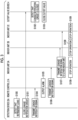
- Fig. 3 is a sequence diagram showing an example of processing of the air conditioning system according to the first embodiment.
- the refrigerant sensor 220 of the detection device 22A detects that the refrigerant has leaked into the air-conditioned area A (step S100).
- the CPU 222 of the detection device 22A turns on the relay 221 to close the leakage notification circuit 25 (step S101).
- the CPU 41 of the cutoff valve device 4 detects that the leakage notification circuit 25 between the detection device 22A and the cutoff valve device 4 is closed (step S102), the CPU 41 closes the cutoff valve 40 to cut off the circulation of the refrigerant (step S103). Accordingly, further leakage of the refrigerant is suppressed.
- the CPU 222 of the detection device 22A transmits a leakage detection signal indicating that the leakage of the refrigerant has been detected to the remote control 21A installed in the same air-conditioned area A as the detection device 22A after step S101 or in parallel with step S101 (step S104).
- the remote control 21A When the remote control 21A receives the leakage detection signal from the detection device 22A, the remote control 21A outputs an alarm (step S105).
- the remote control 21A outputs, for example, an alarm via sound and light.
- the remote control 21A transmits the leakage detection signal to the indoor unit 2A installed in the same air-conditioned area A as the remote control 21A after step S105 or in parallel with step S105 (step S106).
- the indoor unit 2A When the indoor unit 2A receives the leakage detection signal from the remote control 21A, the indoor unit 2A transmits the leakage detection signal to the other indoor units 2B and 2C via the indoor and outdoor communication line 24 (step S107), and stops the operation (step S108).
- the indoor units 2B and 2C stop the operation (step S109).
- the indoor unit 2A can notify the other indoor units 2B and 2C that the leakage of the refrigerant is detected in the air-conditioned area A and the circulation of the refrigerant is cut off. Accordingly, the indoor units 2B and 2C can appropriately stop the operation even in a case where the refrigerant leaks in the air-conditioned area A outside the air-conditioned areas for which the indoor units 2B and 2C are responsible.
- the air conditioning system 100 includes the detection device 22 having the relay 221 that closes the leakage notification circuit 25 in a case where the refrigerant sensor 220 detects the leakage of the refrigerant into the air-conditioned area, and the cutoff valve device 4 that closes the cutoff valve 40 in a case where the leakage notification circuit 25 is closed.
- the air conditioning system 100 can notify the cutoff valve device 4 of the presence or absence of the leakage of the refrigerant with a simple configuration in which the relay 221 of the detection device 22 switches between on and off of the leakage notification circuit 25.
- the detection device 22 itself can notify the cutoff valve device 4 that the leakage of the refrigerant has been detected, it is not necessary to add a communication circuit or the like for notifying the cutoff valve device 4 of the leakage of the refrigerant to the substrate of the indoor unit 2. Therefore, the air conditioning system 100 can be configured to be reasonable by using the existing indoor unit 2.
- the simple configuration is adopted in which only the leakage notification circuit 25 is provided between the detection device 22 and the cutoff valve device 4, it is possible to connect any number of the indoor units 2 to one outdoor unit 1 and one cutoff valve device 4.
- the air conditioning system 100 further includes the remote control 21 that is connected to be capable of communicating with both the indoor unit 2 and the detection device 22 which are installed in the same air-conditioned area.
- the remote control 21 transmits the leakage detection signal to the indoor unit 2 in a case where the detection device 22 detects the leakage of the refrigerant into the air-conditioned area.
- the indoor unit 2 stops the operation in a case where the leakage detection signal is received from the remote control 21.
- the air conditioning system 100 can promptly stop the operation of the indoor unit 2 in a case where the leakage of the refrigerant is detected.
- the remote control communication line 23 for transmitting and receiving the leakage detection signal between the indoor unit 2 and the detection device 22 the existing one can be used.
- the indoor unit 2 transmits the leakage detection signal to the other indoor unit 2 via the indoor and outdoor communication line 24. In addition, the indoor unit 2 stops the operation in a case where the leakage detection signal is received from the other indoor unit 2.
- each indoor unit 2 can appropriately stop the operation even in a case where the refrigerant leaks in the air-conditioned area outside the air-conditioned area for which each indoor unit 2 is responsible.
- the remote control 21 outputs an alarm in a case where the detection device 22 detects the leakage of the refrigerant.
- the remote control 21 can transmit that the refrigerant leaks to the person in the air-conditioned area where the remote control 21 is provided.
- Fig. 4 is a sequence diagram showing an example of processing of an air conditioning system according to other embodiments.
- the detection device 22 transmits the leakage detection signal to the indoor unit 2 via the remote control 21.
- the present disclosure is not limited thereto.
- the detection device 22 may be configured to detect that the leakage notification circuit 25 of another air-conditioned area is closed.
- Fig. 4 shows an example of processing executed by the indoor unit 2B, the remote control 21B, and the detection device 22B of the air-conditioned area B in a case where the leakage of the refrigerant is detected in the air-conditioned area A. Since the processing of the remote control 21A and the detection device 22A in the air-conditioned area A and the processing of the cutoff valve device 4 are the same as those in the first embodiment, the description thereof will be omitted. In addition, in the example of Fig. 4 , when the detection device 22A detects the leakage of the refrigerant, the indoor unit 2A of the air-conditioned area A omits processing of transmitting the leakage detection signal to the other indoor units 2B and 2C (step S107 of Fig. 3 ) and stops the operation.
- the detection device 22B of the air-conditioned area B always monitors whether the leakage notification circuit 25 of the other air-conditioned areas A and C is opened or closed.
- the detection device 22B detects that the leakage notification circuit 25 of the air-conditioned area A is closed (step S200)
- the detection device 22B transmits the leakage detection signal to the remote control 21B (step S201).
- the detection device 22B may generate and transmit a signal (the other area leakage detection signal) different from that in a case where the detection device 22B detects the leakage of the refrigerant, so that the fact that the leakage of the refrigerant is detected in the other air-conditioned area A can be identified.
- the remote control 21B When the remote control 21B receives the other area leakage detection signal from the detection device 22B, the remote control 21B transmits the other area leakage detection signal to the indoor unit 2B (step S202).
- the indoor unit 2B When the indoor unit 2B receives the other area leakage detection signal from the remote control 21B, the indoor unit 2B stops the operation (step S203).
- the same processing is also executed on the indoor unit 2C, the remote control 21C, and the detection device 22C of the air-conditioned area C as on each device of the air-conditioned area B.
- each indoor unit 2 can quickly detect the presence or absence of the leakage of the refrigerant in the other air-conditioned area from the state of the leakage notification circuit 25 and appropriately stop the operation.
- the air conditioning system 100 can notify the cutoff valve device 4 of the presence or absence of the leakage of the refrigerant with a simple configuration in which the relay 221 of the detection device 22 switches between on and off of the leakage notification circuit 25.
- the detection device 22 itself can notify the cutoff valve device 4 that the leakage of the refrigerant has been detected, it is not necessary to add a communication circuit or the like for notifying the cutoff valve device 4 of the leakage of the refrigerant to the substrate of the indoor unit 2. Therefore, the air conditioning system 100 can be configured to be reasonable by using the existing indoor unit 2.
- the simple configuration is adopted in which only the leakage notification circuit 25 is provided between the detection device 22 and the cutoff valve device 4, it is possible to connect any number of the indoor units 2 to one outdoor unit 1 and one cutoff valve device 4.
- the air conditioning system 100 further includes a remote controller 21 that is provided in each of a plurality of the air-conditioned areas and that is connected to be capable of communicating with both the indoor unit 2 and the detection device 22 which are installed in the air-conditioned area, in which the remote controller 21 transmits a leakage detection signal to the indoor unit 2 when the detection device 22 detects the leakage of the refrigerant, and the indoor unit 2 stops an operation when the leakage detection signal is received.
- a remote controller 21 that is provided in each of a plurality of the air-conditioned areas and that is connected to be capable of communicating with both the indoor unit 2 and the detection device 22 which are installed in the air-conditioned area, in which the remote controller 21 transmits a leakage detection signal to the indoor unit 2 when the detection device 22 detects the leakage of the refrigerant, and the indoor unit 2 stops an operation when the leakage detection signal is received.
- the air conditioning system 100 can promptly stop the operation of the indoor unit 2 in a case where the leakage of the refrigerant is detected.
- the remote control communication line 23 for transmitting and receiving the leakage detection signal between the indoor unit 2 and the detection device 22 the existing one can be used.
- the indoor unit 2 transmits the leakage detection signal to another indoor unit 2 via a communication line 24 that connects each of the plurality of indoor units 2 such that the plurality of indoor units 2 are capable of communicating with each other, when the leakage detection signal is received from the remote controller 21.
- each indoor unit 2 can appropriately stop the operation even in a case where the refrigerant leaks in the air-conditioned area outside the air-conditioned area for which each indoor unit 2 is responsible.
- the detection device 22 detects leakage of the refrigerant in another air-conditioned area when a leakage notification circuit 25 of another detection device 22 is closed, and the remote controller 21 transmits the leakage detection signal to the indoor unit 2 when the detection device 22 detects the leakage of the refrigerant in the other air-conditioned area.
- each indoor unit 2 can quickly detect the presence or absence of the leakage of the refrigerant in the other air-conditioned area from the state of the leakage notification circuit 25 and appropriately stop the operation.
- the remote controller 21 outputs an alarm when the detection device 22 detects the leakage of the refrigerant.
- the remote control 21 can transmit that the refrigerant leaks to the person in the air-conditioned area where the remote control 21 is provided.
- a method for controlling an air conditioning system 100 including an outdoor unit 1, a plurality of indoor units 2, and refrigerant piping 3 that circulates a refrigerant between the outdoor unit 1 and the indoor unit 2 includes a step of detecting leakage of the refrigerant into an air-conditioned area for which each of the plurality of indoor units 2 is responsible, via a refrigerant sensor 220 provided in the air-conditioned area, a step of closing a leakage notification circuit 25 via a relay 221 when the refrigerant sensor 220 detects the leakage of the refrigerant, and a step of closing a cutoff valve 40 provided in the refrigerant piping 3 when the leakage notification circuit 25 is closed.
Landscapes
- Engineering & Computer Science (AREA)
- Mechanical Engineering (AREA)
- General Engineering & Computer Science (AREA)
- Chemical & Material Sciences (AREA)
- Combustion & Propulsion (AREA)
- Physics & Mathematics (AREA)
- Thermal Sciences (AREA)
- Air Conditioning Control Device (AREA)
Applications Claiming Priority (2)
| Application Number | Priority Date | Filing Date | Title |
|---|---|---|---|
| JP2022066729A JP2023157070A (ja) | 2022-04-14 | 2022-04-14 | 空調システムおよび空調システムの制御方法 |
| PCT/JP2023/011453 WO2023199719A1 (ja) | 2022-04-14 | 2023-03-23 | 空調システムおよび空調システムの制御方法 |
Publications (2)
| Publication Number | Publication Date |
|---|---|
| EP4477966A1 true EP4477966A1 (de) | 2024-12-18 |
| EP4477966A4 EP4477966A4 (de) | 2025-05-07 |
Family
ID=88329460
Family Applications (1)
| Application Number | Title | Priority Date | Filing Date |
|---|---|---|---|
| EP23788139.6A Withdrawn EP4477966A4 (de) | 2022-04-14 | 2023-03-23 | Klimatisierungssystem und verfahren zur steuerung des klimatisierungssystems |
Country Status (3)
| Country | Link |
|---|---|
| EP (1) | EP4477966A4 (de) |
| JP (1) | JP2023157070A (de) |
| WO (1) | WO2023199719A1 (de) |
Families Citing this family (1)
| Publication number | Priority date | Publication date | Assignee | Title |
|---|---|---|---|---|
| WO2026009362A1 (ja) * | 2024-07-04 | 2026-01-08 | 三菱電機株式会社 | 冷凍サイクル装置および冷凍装置 |
Family Cites Families (9)
| Publication number | Priority date | Publication date | Assignee | Title |
|---|---|---|---|---|
| WO2017002215A1 (ja) * | 2015-06-30 | 2017-01-05 | 三菱電機株式会社 | 冷媒漏洩検知システム |
| WO2017163321A1 (ja) * | 2016-03-23 | 2017-09-28 | 三菱電機株式会社 | 冷凍サイクル装置 |
| JP6828401B2 (ja) * | 2016-12-02 | 2021-02-10 | 三菱電機株式会社 | 空気調和機 |
| US11898763B2 (en) * | 2018-07-25 | 2024-02-13 | Daikin Industries, Ltd. | Air conditioning system with refrigerant leak management |
| WO2020110425A1 (ja) * | 2018-11-26 | 2020-06-04 | 日立ジョンソンコントロールズ空調株式会社 | 空気調和システム及び冷媒漏洩防止システム |
| JP7315845B2 (ja) | 2019-11-29 | 2023-07-27 | ダイキン工業株式会社 | 空気調和装置 |
| JP7495594B2 (ja) * | 2020-02-05 | 2024-06-05 | ダイキン工業株式会社 | 空気調和システム |
| JP7057519B2 (ja) * | 2020-02-05 | 2022-04-20 | ダイキン工業株式会社 | 空気調和システム |
| JP7451051B2 (ja) | 2020-10-19 | 2024-03-18 | 東洋刃物株式会社 | 中抜き用のスリッタ装置 |
-
2022
- 2022-04-14 JP JP2022066729A patent/JP2023157070A/ja active Pending
-
2023
- 2023-03-23 EP EP23788139.6A patent/EP4477966A4/de not_active Withdrawn
- 2023-03-23 WO PCT/JP2023/011453 patent/WO2023199719A1/ja not_active Ceased
Also Published As
| Publication number | Publication date |
|---|---|
| EP4477966A4 (de) | 2025-05-07 |
| JP2023157070A (ja) | 2023-10-26 |
| WO2023199719A1 (ja) | 2023-10-19 |
Similar Documents
| Publication | Publication Date | Title |
|---|---|---|
| ES3057092T3 (en) | Refrigeration cycle system | |
| US12595923B2 (en) | Leakage detection and mitigation system | |
| US9377210B2 (en) | HVAC communication bus decoders and corresponding methods | |
| ES2733800T3 (es) | Sistema de acondicionamiento de aire | |
| JP5517789B2 (ja) | 空気調和機 | |
| EP3633282B1 (de) | Klimatisierungsvorrichtung | |
| US20220290885A1 (en) | Air conditioning system | |
| EP3623716B1 (de) | Klimaanlage und verfahren zur einstellung der kältemittelmenge dafür | |
| EP4056925B1 (de) | Klimaanlage | |
| JP6572622B2 (ja) | 空調換気システム | |
| US20240401829A1 (en) | Air conditioning system | |
| GB2607499A (en) | Air conditioning system | |
| CN116085938A (zh) | 一种冷媒安全控制装置、空调器、方法及介质 | |
| WO2018154652A1 (ja) | リモコン装置、空調機及び空調システム | |
| US20240068685A1 (en) | Safety System For Air Handling Unit | |
| WO2023199719A1 (ja) | 空調システムおよび空調システムの制御方法 | |
| JP2017011542A (ja) | 制御システム、制御方法、及びプログラム | |
| CN115053102A (zh) | 空调系统 | |
| US10317106B2 (en) | Air conditioner | |
| KR101075229B1 (ko) | 시스템 에어컨의 통신에러 진단장치 및 그 방법 | |
| KR20150004616U (ko) | 선박의 공조 제어장치 | |
| KR101660597B1 (ko) | 원격 가스밸브차단이 가능한 선박 | |
| JP2010140424A (ja) | 予防・保安システム | |
| WO2024018594A1 (ja) | マルチ型空気調和装置 | |
| Guide | Pelican |
Legal Events
| Date | Code | Title | Description |
|---|---|---|---|
| STAA | Information on the status of an ep patent application or granted ep patent |
Free format text: STATUS: THE INTERNATIONAL PUBLICATION HAS BEEN MADE |
|
| PUAI | Public reference made under article 153(3) epc to a published international application that has entered the european phase |
Free format text: ORIGINAL CODE: 0009012 |
|
| STAA | Information on the status of an ep patent application or granted ep patent |
Free format text: STATUS: REQUEST FOR EXAMINATION WAS MADE |
|
| 17P | Request for examination filed |
Effective date: 20240909 |
|
| AK | Designated contracting states |
Kind code of ref document: A1 Designated state(s): AL AT BE BG CH CY CZ DE DK EE ES FI FR GB GR HR HU IE IS IT LI LT LU LV MC ME MK MT NL NO PL PT RO RS SE SI SK SM TR |
|
| A4 | Supplementary search report drawn up and despatched |
Effective date: 20250404 |
|
| RIC1 | Information provided on ipc code assigned before grant |
Ipc: F24F 11/88 20180101ALI20250331BHEP Ipc: F25B 49/02 20060101ALI20250331BHEP Ipc: F25B 41/24 20210101ALI20250331BHEP Ipc: F24F 11/526 20180101ALI20250331BHEP Ipc: F24F 11/36 20180101AFI20250331BHEP |
|
| DAV | Request for validation of the european patent (deleted) | ||
| DAX | Request for extension of the european patent (deleted) | ||
| STAA | Information on the status of an ep patent application or granted ep patent |
Free format text: STATUS: THE APPLICATION IS DEEMED TO BE WITHDRAWN |
|
| 18D | Application deemed to be withdrawn |
Effective date: 20251025 |