EP4474604A2 - Boîte de stockage assemblée - Google Patents
Boîte de stockage assemblée Download PDFInfo
- Publication number
- EP4474604A2 EP4474604A2 EP24208126.3A EP24208126A EP4474604A2 EP 4474604 A2 EP4474604 A2 EP 4474604A2 EP 24208126 A EP24208126 A EP 24208126A EP 4474604 A2 EP4474604 A2 EP 4474604A2
- Authority
- EP
- European Patent Office
- Prior art keywords
- disposed
- side plate
- positioning
- box cover
- storage box
- Prior art date
- Legal status (The legal status is an assumption and is not a legal conclusion. Google has not performed a legal analysis and makes no representation as to the accuracy of the status listed.)
- Granted
Links
Images







Classifications
-
- B—PERFORMING OPERATIONS; TRANSPORTING
- B65—CONVEYING; PACKING; STORING; HANDLING THIN OR FILAMENTARY MATERIAL
- B65D—CONTAINERS FOR STORAGE OR TRANSPORT OF ARTICLES OR MATERIALS, e.g. BAGS, BARRELS, BOTTLES, BOXES, CANS, CARTONS, CRATES, DRUMS, JARS, TANKS, HOPPERS, FORWARDING CONTAINERS; ACCESSORIES, CLOSURES, OR FITTINGS THEREFOR; PACKAGING ELEMENTS; PACKAGES
- B65D11/00—Containers having bodies formed by interconnecting or uniting two or more rigid, or substantially rigid, components made wholly or mainly of plastics material
- B65D11/18—Containers having bodies formed by interconnecting or uniting two or more rigid, or substantially rigid, components made wholly or mainly of plastics material collapsible, i.e. with walls hinged together or detachably connected
- B65D11/1866—Containers having bodies formed by interconnecting or uniting two or more rigid, or substantially rigid, components made wholly or mainly of plastics material collapsible, i.e. with walls hinged together or detachably connected with detachable components
- B65D11/1873—Containers having bodies formed by interconnecting or uniting two or more rigid, or substantially rigid, components made wholly or mainly of plastics material collapsible, i.e. with walls hinged together or detachably connected with detachable components all walls are detached from each other to collapse the container
-
- B—PERFORMING OPERATIONS; TRANSPORTING
- B65—CONVEYING; PACKING; STORING; HANDLING THIN OR FILAMENTARY MATERIAL
- B65D—CONTAINERS FOR STORAGE OR TRANSPORT OF ARTICLES OR MATERIALS, e.g. BAGS, BARRELS, BOTTLES, BOXES, CANS, CARTONS, CRATES, DRUMS, JARS, TANKS, HOPPERS, FORWARDING CONTAINERS; ACCESSORIES, CLOSURES, OR FITTINGS THEREFOR; PACKAGING ELEMENTS; PACKAGES
- B65D11/00—Containers having bodies formed by interconnecting or uniting two or more rigid, or substantially rigid, components made wholly or mainly of plastics material
- B65D11/20—Details of walls made of plastics material
- B65D11/22—Reinforcing for strengthening parts of members
- B65D11/26—Local reinforcements, e.g. adjacent to closures
-
- B—PERFORMING OPERATIONS; TRANSPORTING
- B65—CONVEYING; PACKING; STORING; HANDLING THIN OR FILAMENTARY MATERIAL
- B65D—CONTAINERS FOR STORAGE OR TRANSPORT OF ARTICLES OR MATERIALS, e.g. BAGS, BARRELS, BOTTLES, BOXES, CANS, CARTONS, CRATES, DRUMS, JARS, TANKS, HOPPERS, FORWARDING CONTAINERS; ACCESSORIES, CLOSURES, OR FITTINGS THEREFOR; PACKAGING ELEMENTS; PACKAGES
- B65D43/00—Lids or covers for rigid or semi-rigid containers
- B65D43/14—Non-removable lids or covers
- B65D43/16—Non-removable lids or covers hinged for upward or downward movement
- B65D43/163—Non-removable lids or covers hinged for upward or downward movement the container and the lid being made separately
- B65D43/164—Non-removable lids or covers hinged for upward or downward movement the container and the lid being made separately and connected by interfitting hinge elements integrally with the container and the lid formed respectively
- B65D43/165—Non-removable lids or covers hinged for upward or downward movement the container and the lid being made separately and connected by interfitting hinge elements integrally with the container and the lid formed respectively these elements being assembled by a separate pin-like member
-
- B—PERFORMING OPERATIONS; TRANSPORTING
- B65—CONVEYING; PACKING; STORING; HANDLING THIN OR FILAMENTARY MATERIAL
- B65D—CONTAINERS FOR STORAGE OR TRANSPORT OF ARTICLES OR MATERIALS, e.g. BAGS, BARRELS, BOTTLES, BOXES, CANS, CARTONS, CRATES, DRUMS, JARS, TANKS, HOPPERS, FORWARDING CONTAINERS; ACCESSORIES, CLOSURES, OR FITTINGS THEREFOR; PACKAGING ELEMENTS; PACKAGES
- B65D43/00—Lids or covers for rigid or semi-rigid containers
- B65D43/14—Non-removable lids or covers
- B65D43/16—Non-removable lids or covers hinged for upward or downward movement
- B65D43/163—Non-removable lids or covers hinged for upward or downward movement the container and the lid being made separately
- B65D43/166—Non-removable lids or covers hinged for upward or downward movement the container and the lid being made separately and connected by separate interfitting hinge elements fixed to the container and the lid respectively
- B65D43/167—Non-removable lids or covers hinged for upward or downward movement the container and the lid being made separately and connected by separate interfitting hinge elements fixed to the container and the lid respectively these elements being assembled by a separate pin-like member
-
- B—PERFORMING OPERATIONS; TRANSPORTING
- B65—CONVEYING; PACKING; STORING; HANDLING THIN OR FILAMENTARY MATERIAL
- B65D—CONTAINERS FOR STORAGE OR TRANSPORT OF ARTICLES OR MATERIALS, e.g. BAGS, BARRELS, BOTTLES, BOXES, CANS, CARTONS, CRATES, DRUMS, JARS, TANKS, HOPPERS, FORWARDING CONTAINERS; ACCESSORIES, CLOSURES, OR FITTINGS THEREFOR; PACKAGING ELEMENTS; PACKAGES
- B65D43/00—Lids or covers for rigid or semi-rigid containers
- B65D43/14—Non-removable lids or covers
- B65D43/22—Devices for holding in closed position, e.g. clips
-
- B—PERFORMING OPERATIONS; TRANSPORTING
- B65—CONVEYING; PACKING; STORING; HANDLING THIN OR FILAMENTARY MATERIAL
- B65D—CONTAINERS FOR STORAGE OR TRANSPORT OF ARTICLES OR MATERIALS, e.g. BAGS, BARRELS, BOTTLES, BOXES, CANS, CARTONS, CRATES, DRUMS, JARS, TANKS, HOPPERS, FORWARDING CONTAINERS; ACCESSORIES, CLOSURES, OR FITTINGS THEREFOR; PACKAGING ELEMENTS; PACKAGES
- B65D43/00—Lids or covers for rigid or semi-rigid containers
- B65D43/14—Non-removable lids or covers
- B65D43/24—Devices for retaining in open position
-
- E—FIXED CONSTRUCTIONS
- E05—LOCKS; KEYS; WINDOW OR DOOR FITTINGS; SAFES
- E05C—BOLTS OR FASTENING DEVICES FOR WINGS, SPECIALLY FOR DOORS OR WINDOWS
- E05C17/00—Devices for holding wings open; Devices for limiting opening of wings or for holding wings open by a movable member extending between frame and wing; Braking devices, stops or buffers, combined therewith
- E05C17/02—Devices for holding wings open; Devices for limiting opening of wings or for holding wings open by a movable member extending between frame and wing; Braking devices, stops or buffers, combined therewith by mechanical means
- E05C17/04—Devices for holding wings open; Devices for limiting opening of wings or for holding wings open by a movable member extending between frame and wing; Braking devices, stops or buffers, combined therewith by mechanical means with a movable bar or equivalent member extending between frame and wing
- E05C17/12—Devices for holding wings open; Devices for limiting opening of wings or for holding wings open by a movable member extending between frame and wing; Braking devices, stops or buffers, combined therewith by mechanical means with a movable bar or equivalent member extending between frame and wing consisting of a single rod
- E05C17/20—Devices for holding wings open; Devices for limiting opening of wings or for holding wings open by a movable member extending between frame and wing; Braking devices, stops or buffers, combined therewith by mechanical means with a movable bar or equivalent member extending between frame and wing consisting of a single rod sliding through a guide
- E05C17/22—Devices for holding wings open; Devices for limiting opening of wings or for holding wings open by a movable member extending between frame and wing; Braking devices, stops or buffers, combined therewith by mechanical means with a movable bar or equivalent member extending between frame and wing consisting of a single rod sliding through a guide with braking, clamping or securing means in the guide
-
- E—FIXED CONSTRUCTIONS
- E05—LOCKS; KEYS; WINDOW OR DOOR FITTINGS; SAFES
- E05C—BOLTS OR FASTENING DEVICES FOR WINGS, SPECIALLY FOR DOORS OR WINDOWS
- E05C17/00—Devices for holding wings open; Devices for limiting opening of wings or for holding wings open by a movable member extending between frame and wing; Braking devices, stops or buffers, combined therewith
- E05C17/02—Devices for holding wings open; Devices for limiting opening of wings or for holding wings open by a movable member extending between frame and wing; Braking devices, stops or buffers, combined therewith by mechanical means
- E05C17/04—Devices for holding wings open; Devices for limiting opening of wings or for holding wings open by a movable member extending between frame and wing; Braking devices, stops or buffers, combined therewith by mechanical means with a movable bar or equivalent member extending between frame and wing
- E05C17/36—Devices for holding wings open; Devices for limiting opening of wings or for holding wings open by a movable member extending between frame and wing; Braking devices, stops or buffers, combined therewith by mechanical means with a movable bar or equivalent member extending between frame and wing comprising a flexible member, e.g. chains
-
- B—PERFORMING OPERATIONS; TRANSPORTING
- B65—CONVEYING; PACKING; STORING; HANDLING THIN OR FILAMENTARY MATERIAL
- B65D—CONTAINERS FOR STORAGE OR TRANSPORT OF ARTICLES OR MATERIALS, e.g. BAGS, BARRELS, BOTTLES, BOXES, CANS, CARTONS, CRATES, DRUMS, JARS, TANKS, HOPPERS, FORWARDING CONTAINERS; ACCESSORIES, CLOSURES, OR FITTINGS THEREFOR; PACKAGING ELEMENTS; PACKAGES
- B65D2543/00—Lids or covers essentially for box-like containers
- B65D2543/00009—Details of lids or covers for rigid or semi-rigid containers
- B65D2543/00018—Overall construction of the lid
- B65D2543/00231—Overall construction of the lid made of several pieces
-
- B—PERFORMING OPERATIONS; TRANSPORTING
- B65—CONVEYING; PACKING; STORING; HANDLING THIN OR FILAMENTARY MATERIAL
- B65D—CONTAINERS FOR STORAGE OR TRANSPORT OF ARTICLES OR MATERIALS, e.g. BAGS, BARRELS, BOTTLES, BOXES, CANS, CARTONS, CRATES, DRUMS, JARS, TANKS, HOPPERS, FORWARDING CONTAINERS; ACCESSORIES, CLOSURES, OR FITTINGS THEREFOR; PACKAGING ELEMENTS; PACKAGES
- B65D2543/00—Lids or covers essentially for box-like containers
- B65D2543/00009—Details of lids or covers for rigid or semi-rigid containers
- B65D2543/00018—Overall construction of the lid
- B65D2543/00259—Materials used
- B65D2543/00296—Plastic
-
- B—PERFORMING OPERATIONS; TRANSPORTING
- B65—CONVEYING; PACKING; STORING; HANDLING THIN OR FILAMENTARY MATERIAL
- B65D—CONTAINERS FOR STORAGE OR TRANSPORT OF ARTICLES OR MATERIALS, e.g. BAGS, BARRELS, BOTTLES, BOXES, CANS, CARTONS, CRATES, DRUMS, JARS, TANKS, HOPPERS, FORWARDING CONTAINERS; ACCESSORIES, CLOSURES, OR FITTINGS THEREFOR; PACKAGING ELEMENTS; PACKAGES
- B65D2543/00—Lids or covers essentially for box-like containers
- B65D2543/00009—Details of lids or covers for rigid or semi-rigid containers
- B65D2543/00444—Contact between the container and the lid
- B65D2543/00574—Contact between the container and the lid secured locally, i.e. a lot less than half the periphery
Definitions
- the present disclosure relates to an assemblable storage box, in particular relates to an assemblable plastic storage box.
- Storage boxes are inseparable for every family in life, the storage box can be used to store clothes, tools, daily necessities, etc., and the storage box can make the living environment more clean and tidy, especially when moving or traveling, which is convenient to put things.
- plastic storage boxes have the following technical problems: first, the plastic storage boxes cannot be disassembled, a larger amount of space is taken up during both transportation and storage, which is not conducive to reducing transportation costs, and are easily crushed during transportation; Second, a load-bearing weight of a box cover is distributed to each side plate of a box body, and an upper edge of a front side plate of the box body has a large width and is suspended as an entirety, when bearing a larger weight, the front side plate of the box body is easily deformed and arches outwards, so the storage box has a poor load-bearing capacity; Third, when the storage box is used outdoors, rainwater can easily penetrate into the box body from a gap between the side plates of the box body, causing items to get wet, therefore, the waterproof performance of the storage box is not good; Fourth, after the box cover is opened, the box cover hangs down on a back of the box body, and a turning angle of the box cover is very large, an operation is inconvenient, in particular, the box cover cannot
- An assemblable storage box comprises a box body comprising a top surface with an opening and a box cover configured to cover the opening of the box body, the box body comprises a bottom plate and four side plates comprising a front side plate, a rear side plate, a left side plate, and a right side plate, two adjacent side plates are detachably clamped together, bottom portions of the four side plates comprising the front side plate, the rear side plate, the left side plate, and the right side plate are disposed with support countertops, four sides of the bottom plate horizontally extend outward to define positioning edges respectively, the positioning edges of the four sides of the bottom plate respectively abut upper sides of the support countertops of the four side plates comprising the front side plate, the rear side plate, the left side plate, and the right side plate, positioning fasteners are further provided, and the positioning fasteners are further provided, and the positioning fasteners
- the two adjacent side plates are clamped together by a positioning column and a positioning hole, the positioning column and the positioning hole are respectively disposed on one of the two adjacent side plates, a free end of the positioning column comprises a cap, the positioning hole is gourd shaped, and the cap of the positioning column is configured to be disposed in and hung on a narrower end of the positioning hole from a wider end of the positioning hole.
- the two side plates comprising the left side plate and the right side plate are clamped between the two side plates comprising the front side plate and the rear side plate, inner surfaces of the two side plates comprising the left side plate and the right side plate are disposed with the positioning columns, end faces of the two side plates comprising the front side plate and the rear side plate are disposed with the positioning holes, and the positioning holes comprises narrow tops and wide bottoms.
- the side plates comprise rectangular frames and plates, four sides of the plates surround the frames, and upper surfaces of bottom edges of the frames define the support countertops of the side plates.
- the bottom plate is a blister board, and the bottom plate is disposed with honeycomb grooves.
- a rear side edge of the box cover and a top edge of the rear side plate are both disposed with a connecting base, the connecting base of the box cover and the connecting base of the box body are connected together by a shaft core to enable the box cover to be rotated to be opened and to be closed, and the shaft core is detachable.
- one end of the shaft core is disposed with a cap
- the other end of the shaft core is centrally symmetrically disposed with two elastic arms
- opposite outer side walls of the two elastic arms are respectively disposed with positioning protrusions
- the cap and the positioning protrusions cooperate to clamp the connecting base of the box cover and the connecting base of the box body.
- the positioning protrusions comprise front guide slopes and rear guide slopes.
- the guide slopes are provided to enable the positioning protrusions to be transmitted to the axial holes smoothly, and the shaft core is assembled and disassembled more smoothly and effortlessly.
- a middle portion of an end surface of the other end of the shaft core is disposed with a V-shaped groove, and the V-shaped groove divides the other end of the shaft core into the two elastic arms.
- connecting base and the box cover are fastened together, and the connecting base and the box body are fastened together.
- an outer edge of a top surface of the rear side plate is disposed with a step groove, and the connecting base of the box body is disposed in the step groove.
- an outer side of the upper edge of the front side plate comprises a step groove, a handle and a lock piece configured to be mated and connected to each other are further provided, the handle is rotatably connected to the U-shaped fastener, and the lock piece is disposed on an edge position of the step groove.
- the box cover comprises a plastic panel and a plastic frame, four sides of the plastic panel is connected to the plastic frame, and the U-shaped fastener and the plastic frame are mated and connected to each other.
- the front side plate comprises a rectangular frame and a plate, four sides of the plate surround the frame, the frame is disposed with a reinforcing rod, and the reinforcing rod is vertically disposed on a middle portion of the frame.
- a splice gap is defined between the two adjacent side plates, the side plates comprise frames and plates connected together, the rectangular frames are disposed along edges of four sides of the plates, and in the two adjacent side plates disposed end-to-end: the frame of one side plate extends outward to define a side wing, and the side wing covers the splice gap between the two side plates from an outer side.
- the plates are plastic blister boards, and the frames are hollow plastic members.
- the four sides of the plates are bent inward to define folded edges, the folded edges surround the frames from the outer side, the frames are disposed with pressing edges, and the pressing edges press edges of the folded edges.
- the two side plates comprising the left side plate and the right side plate are clamped by the two side plates comprising the front side plate and the rear side plate, and the frames of the front side plate and the rear side plate define the side wings.
- a rear side of the box cover is rotatably connected to the rear side plate
- a self-positioning structure is disposed between the box cover and the left side plate or the right side plate
- the self-positioning structure comprises a support rod, a fixing base, and a friction block
- the fixing base is disposed on the left side plate or the right side plate
- the fixing base is disposed with a slide groove passing through an upper top surface and a lower bottom surface of the fixing base
- the fixing base is further disposed with a receiving hole in communication with the slide groove
- one end of the support rod is pivotally connected to a side wall of the box cover, the other end of the support rod passes through the slide groove and extends out of the fixing base in a downward direction
- the support rod is configured to slide and swing relative to the slide groove
- the friction block is disposed in the receiving hole and is in friction connection with the support rod
- a frictional force between the friction block and the support rod positions the support rod
- the support rod is configured to be pulled to move by overcoming
- an inner surface of the receiving hole comprises an internal thread, an elastic member and a screw bolt cooperating with the internal thread are further provided, and two ends of the elastic member abut the friction block and the screw bolt respectively.
- the box cover is disposed with a hinge base, and the one end of the support rod is pivotally connected to the hinge base.
- the hinge base is disposed with a positioning pin
- the box cover comprises a plurality of positioning holes configured to cooperate with the positioning pin
- the positioning pin is configured to be clamped to one of the positioning holes.
- a rear side of the box cover is rotatably connected to the rear side plate, a flexible connection belt is further provided, the flexible connection belt is bendable, two ends of the flexible connection belt are respectively disposed with fasteners, a side edge of the box cover is disposed with a first lock hole at a position adjacent to a rotation axis between the box cover and the box body, a side plate of the box body disposed on the same side of the first lock hole is disposed with a second lock hole at a position adjacent to the rotation axis between the box cover and the box body, the fasteners of the two ends of the flexible connection belt are respectively disposed in the first lock hole and the second lock hole; after the box cover is opened, the flexible connection belt is straightened, and connection lines of three points projected on a plane by the first lock hole, the second lock hole, and the rotation axis define an obtuse triangle.
- the flexible connection belt is a three-step structure, and comprises a body portion disposed on a middle portion and two connection portions disposed on two ends, the body portion and the connection portions are perpendicular to each other, the two fasteners are respectively disposed on the two connection portions, and the flexible connection belt is integrally formed by PE, HDPE, or PP.
- the flexible connection belt is disposed in the storage box.
- the box cover comprises a panel and a frame disposed along four sides of the panel, a periphery of the panel is connected to the frame, the first lock hole is disposed on the frame;
- the side plates comprise plates and frames disposed along four sides of the plates, peripheries of the plates are connected to the frames, and the second lock hole is disposed on the frame of one side plate.
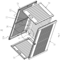
- the box body 10 comprises a bottom plate 11 and four side plates 12 comprising a front side plate, a rear side plate, a left side plate, and a right side plate, two adjacent side plates 12 are detachably clamped together, and the bottom plate 11 closes a bottom surface of the box body 10.
- Bottoms of the four side plates 12 comprising the front side plate, the rear side plate, the left side plate, and the right side plate are all disposed with support countertops 121, four sides of the bottom plate 11 respectively extend horizontally outward to define a positioning edge 111, and the positioning edges 111 of the four sides of the bottom plate 11 respectively abut upper sides of the support countertops 121 of the four side plates comprising the front side plate, the rear side plate, the left side plate, and the right side plate.
- a plurality of positioning fasteners 30 is further provided, and the positioning fasteners 30 are fastened to the side plates 12 to enable the positioning edges 111 to tightly press on the upper sides of the support countertops 121.
- the four side plates 12 comprising the front side plate, the rear side plate, the left side plate, and the right side plate can be disassembled and assembled, a positioning of the bottom plate can be released after the positioning fasteners 30 are disassembled, therefore, assembly and disassembly are very convenient.
- the two side plates 12 comprising the left side plate and the right side plate are sandwiched between the two side plates 12 comprising the front side plate and the rear side plate, the positioning columns 13 are disposed on side surfaces of the two side plates 12 comprising the left side plate and the right side plate, the positioning holes 14 are disposed on edges of inner sides of the two side plates 12 comprising the front side plate and the rear side plate, and the positioning hole 14 comprise narrow tops and wide bottoms.
- the two side plates 12 comprising the front side plate and the rear side plate are configured to lower downward due to their own weight to enable the positioning columns 13 to hang on the positioning holes 14.
- the bottom plate 11 is a blister board, and comprises honeycomb grooves.
- the four sides of the bottom plate 11 are all folded upward to define block edges 112, and upper edges of the block edges 112 horizontally extend outward to define the positioning edges 111.
- the side plates 12 comprise rectangular frames 122 and plates 123, the frames 122 stand vertically, and four sides of the plates 123 surround the frames 122. Upper surfaces of bottom edges of the frames 122 define the support countertops 121 of the side plates 12.
- the plates 123 are blister boards
- the frames 122 are provided to provide strength to the side plates 12 while enabling the thicknesses of the plates 12 to be reduced, so as to not only save materials but also enable the box body 10 to be lighter, and the frames 122 can be hollow plastic members.
- the positioning fasteners 30 are also plastic members, the positioning edges 111 of the four sides of the bottom plate are disposed with fixing holes, and the support countertops 121 of the side plates 12 are disposed with mounting holes cooperating with the fixing holes.
- the plurality of positioning fasteners 30 are locked to the side plates 12 by the fixing holes and the mounting holes to enable the bottom plate 11 to press on the support countertops 121 of the side plates 12.
- the box cover 20 is rotatably connected to one of the side plates 12.
- the box cover 20 can be a structure that comprises an upper board, a lower board, and a frame disposed between the upper board and the lower board, both the upper board and the lower board are blister boards, pressure resistance and deformation resistance of the box cover 20 can be stronger due to the two-layer board structure, so that when the storage box is assembled and used, an upper side of the box cover 20 can be stacked with items, or function as a seat.
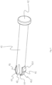
- One end of the shaft core 40 is disposed with a cap 42, and the other end is centrally symmetrically disposed with two elastic arms 44 along the end surface. Opposite outer side walls of the two elastic arms 44 are respectively disposed with positioning protrusions 46.
- the shaft core 40 passes through the axial through hole of the box cover and the axial through hole of the connecting base of the box body, and enables the connecting base of the box cover to be connected to the connecting base of the box body.
- the cap 42 cooperates with the positioning protrusions 46 to clamp the connecting base of the box cover and the connecting base of the box body. In this way, the two connecting bases can rotate freely about the shaft core 40 functioning as a rotation axis.
- the shaft core 40 is a plastic part integrally formed, and the positioning protrusions 46 have front guide slopes 462 and rear guide slopes 464.
- a V-shaped groove 48 is disposed on a middle portion of the end surface of the other end of the shaft core 40, and the V-shaped groove 48 divides the other end of the shaft core into the two elastic arms 44. That is, the two elastic arms 44 and the shaft core are an integral structure, and the V-shaped groove 48 enables the other end of the shaft core 40 to be more resistant to extrusion and to be difficult to break when the other end of the shaft core 40 is disposed in and separated from the axial through holes of the connecting bases.
- Two connecting bases are respectively fastened to the box cover 20 and the rear side plate 12 of the box body.
- the connecting base of the box cover 10 is disposed on an edge of a rear side of a bottom surface of the box cover 10.
- the connecting base of the box body 20 is disposed on a top portion of the rear side plate 12 of the box body.
- an outer edge of a top surface of the rear side plate 12 is disposed with a step groove 124 (referring to Fig. 2 ), and the connecting base is disposed in the step groove 124.
- the step groove 124 is disposed to give space to the connecting base, so that the bottom surface of the box cover 20 can coincide with the top surface of a box body 10 when the box body 10 and the box cover 20 are in a closed state.
- a U-shaped fastener 50 with an opening facing downward is further provided.
- the U-shaped fastener 50 is disposed below a middle portion of a front side of the box cover 20, and when the box cover 20 is closed, the U-shaped fastener 50 is fastened to an upper edge of the front side plate 12 of the box body 10.
- the U-shaped fastener 50 is configured to position to an upper edge of the front side plate 12 of the box body 10, so that an anti-bending strength of the front side plate 12 is improved.
- An outer side of the upper edge of the front side plate 12 of the box body 10 is disposed with a step groove 125, and is further disposed with a handle 51 and a lock piece 52 configured to be mated and connected with each other.
- the handle 51 is rotatably connected to the U-shaped fastener 50, and the lock piece 52 is disposed on an edge position of the step groove 125. After the box cover 20 is closed, the handle 51 can be hung on and be connected to the lock piece 52.
- the box cover 20 comprises a plastic panel and a plastic frame, and four sides of the plastic panel are connected to the plastic frame.
- the U-shaped fastener 50 and the plastic frame are mated and connected together.
- the plastic frame is disposed with a reinforcing rod 21 (referring to Fig. 1 ), the reinforcing rod 21 divides the plastic frame into two halves comprising a left half and a right half, so that a strength of the box cover 20 is increased.
- the frame 122 of the front side plate 12 of the box body 10 is disposed with a reinforcing rod, and the reinforcing rod is vertically disposed on a middle portion of the frame, so that an anti-bending strength of the front side plate is increased.
- a splice gap 60 is defined between the two adjacent side plates 12.
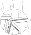
- the side plates 12 comprise plates 123 and frames 122 connected together, the frames 122 are disposed along the edges of the four sides of the plates 123, in the two adjacent side plates 12 disposed end to end, the frame 122 of one side plate 12 extends outward to define a side wing 126, the side wing 126 is a long strip structure vertically disposed, and the side wing 126 covers the splice gap 60 between the two side plates 12 from an outer side.
- the plates 123 bend inward to define folded edges 127, the folded edges 127 surround the frames 122 from the outer side, the frames 122 are disposed with pressing edges 128, and the pressing edges 128 press edges of the folded edges 127.
- the folded edges 127 of the plates 123 are pressed by the pressing edges 128 of the frames 122, in this way, the plates 123 are more tightly attached to the frames 122, so that an overall structure is more compact and stable.
- the side wings 126 are defined on the frames 122 of the front side plate 12 and the rear side plate 12.
- a self-positioning structure 70 is configured to be disposed between the box cover 20 and the left side plate 12 or the right side plate 12.
- the self-positioning structure 70 comprises a support rod 71, a fixing base 72, and a friction block 73.
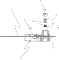
- the fixing base 72 is disposed on one of the side plates 12 of the box body, the fixing base 72 is disposed with a slide groove 721 passing through an upper top surface and a lower bottom surface of the fixing base 72, and the fixing base 72 is further disposed with a receiving hole 722 in communication with the slide groove 721.
- One end of the support rod 71 is pivotally connected to a side wall of the box cover 20, and the other end passes through the slide groove 721.
- a width of the slide groove 721 is greater than a width of the support rod 71, and the support rod 71 is configured to slide and swing relative to the slide groove 721.
- the friction block 73 is disposed in the receiving hole 722 and is in friction connection with and cooperates with the support rod 71, the support rod 71 is positioned due to the frictional force between the friction block 73 and the support rod 71, and the support rod 71 can be pulled to move by overcoming the frictional force.
- the self-positioning structure 70 further comprises an elastic member 74 and a screw bolt 75 cooperating with the internal thread, and two ends of the elastic member 74 respectively abut the friction block 73 and the screw bolt 75.
- the screw bolt 75 rotates to adjust the frictional force between the friction block 73 and the support rod 71, so that the frictional force between the friction block 73 and the support rod 71 is easily adjusted for various sizes of the box cover 20.
- An end of the other end of the support rod 71 is disposed with a positioning hook 711 configured to prevent the support rod 71 and the slide groove 721 from separating from each other.
- the box cover 20 can only be opened to a preset maximum angle, that is, the positioning hook 711 is clamped to the fixing base 72, and the support rod 71 will not be drawn out of the slide groove 721 even where a user opens the box cover 20 with excessive force.
- the box cover 20 is disposed with a hinge base 23, and the one end of the support rod 71 is pivotally connected to the hinge base 23.
- the hinge base 23 is disposed with a positioning pin
- the frame of the box cover 20 comprises a plurality of positioning holes cooperating with the positioning pin
- the positioning pin is clamped to one of the positioning holes.
- the maximum opening angle of the box cover 20 can be preset using the plurality of positioning holes, and the preset maximum opening angle of the box cover is easily adjusted.
- An entirety of the support rod 71 is disposed in a receiving space defined by the box body and the box cover. When the box cover 20 is closed, an appearance of the box body is tidier, and the support rod 71 is prevented from hooking or catching other surrounding objects.
- the support rod 71, the fixing base 72, and the hinge base 23 are all plastic elements.
- a flexible connection belt 80 can also be disposed between the box cover 20 and the box body 10.
- the flexible connection belt 80 can be bent, and two ends of the flexible connection belt 80 are respectively disposed with fasteners 81.
- a side edge of the box cover 20 is disposed with a first lock hole 25 at a position adjacent to a rotation axis (that is, the shaft core 40) between the box cover 20 and the box body 10, and the side plate 12 of the box body 10 on the same side of the first lock hole 25 is disposed with a second lock hole 129 at a position adjacent to the rotation axis.
- the invention may be summarized as follows:
Landscapes
- Engineering & Computer Science (AREA)
- Mechanical Engineering (AREA)
- Rigid Containers With Two Or More Constituent Elements (AREA)
- Stackable Containers (AREA)
- Combinations Of Kitchen Furniture (AREA)
Applications Claiming Priority (8)
| Application Number | Priority Date | Filing Date | Title |
|---|---|---|---|
| CN201820466880.5U CN209284879U (zh) | 2018-04-03 | 2018-04-03 | 一种新型收纳箱 |
| CN201820480545.0U CN208181634U (zh) | 2018-04-03 | 2018-04-03 | 一种拼装收纳箱 |
| CN201820466837.9U CN208957579U (zh) | 2018-04-03 | 2018-04-03 | 一种方便组装的收纳箱 |
| CN201820472588.4U CN208412609U (zh) | 2018-04-03 | 2018-04-03 | 一种箱盖自定位结构 |
| CN201820465365.5U CN208181746U (zh) | 2018-04-03 | 2018-04-03 | 收纳箱开盖限位结构 |
| CN201820467034.5U CN208181743U (zh) | 2018-04-03 | 2018-04-03 | 一种箱盖与箱体的转动连接结构 |
| PCT/CN2019/080976 WO2019192463A1 (fr) | 2018-04-03 | 2019-04-02 | Boîte de stockage assemblée |
| EP19782376.8A EP3778413B1 (fr) | 2018-04-03 | 2019-04-02 | Boîte de stockage assemblée |
Related Parent Applications (1)
| Application Number | Title | Priority Date | Filing Date |
|---|---|---|---|
| EP19782376.8A Division EP3778413B1 (fr) | 2018-04-03 | 2019-04-02 | Boîte de stockage assemblée |
Publications (3)
| Publication Number | Publication Date |
|---|---|
| EP4474604A2 true EP4474604A2 (fr) | 2024-12-11 |
| EP4474604A3 EP4474604A3 (fr) | 2025-02-26 |
| EP4474604B1 EP4474604B1 (fr) | 2025-12-17 |
Family
ID=68099948
Family Applications (2)
| Application Number | Title | Priority Date | Filing Date |
|---|---|---|---|
| EP24208126.3A Active EP4474604B1 (fr) | 2018-04-03 | 2019-04-02 | Boîte de stockage assemblable |
| EP19782376.8A Active EP3778413B1 (fr) | 2018-04-03 | 2019-04-02 | Boîte de stockage assemblée |
Family Applications After (1)
| Application Number | Title | Priority Date | Filing Date |
|---|---|---|---|
| EP19782376.8A Active EP3778413B1 (fr) | 2018-04-03 | 2019-04-02 | Boîte de stockage assemblée |
Country Status (4)
| Country | Link |
|---|---|
| US (1) | US11608208B2 (fr) |
| EP (2) | EP4474604B1 (fr) |
| ES (2) | ES3064432T3 (fr) |
| WO (1) | WO2019192463A1 (fr) |
Families Citing this family (27)
| Publication number | Priority date | Publication date | Assignee | Title |
|---|---|---|---|---|
| US11772857B2 (en) | 2021-01-14 | 2023-10-03 | Beisanne ATSHAN | Food storage container having attached lid |
| CN113243675B (zh) * | 2021-06-04 | 2023-10-31 | 徐州恒盛智谷科技发展有限公司 | 一种具有收纳功能的办公用品放置装置 |
| US11731803B2 (en) * | 2021-07-02 | 2023-08-22 | The Merchant Of Tennis, Inc. | Collapsible crate with stowable hinged lid |
| US11725435B2 (en) * | 2021-10-01 | 2023-08-15 | Michael A Papoulias | Door hinge limiter for automotive vehicle |
| US11629535B2 (en) * | 2021-10-02 | 2023-04-18 | William Steven Kroll | Surface mounted door check device |
| CN113859746A (zh) * | 2021-10-20 | 2021-12-31 | 宁波一象吹塑家具有限公司 | 一种储存箱及其包装结构 |
| USD991710S1 (en) * | 2021-11-10 | 2023-07-11 | Keter Home and Garden Products Ltd. | Storage furniture |
| USD968133S1 (en) * | 2022-04-27 | 2022-11-01 | Jingning Meige Operation Management Co., Ltd | Storage box |
| USD1029498S1 (en) * | 2022-05-03 | 2024-06-04 | Jie Huang | Storage box |
| CN114811319B (zh) * | 2022-05-12 | 2024-11-12 | 国网甘肃省电力公司定西供电公司 | 一种配电网单相接地故障行波测量装置 |
| CN115886446A (zh) * | 2022-07-19 | 2023-04-04 | 雷格工业设计(杭州)有限公司 | 一种快速拼装柜 |
| TWD239108S (zh) * | 2022-09-12 | 2025-07-01 | 聯府塑膠股份有限公司 苗栗縣銅鑼鄉銅鑼村自強路18號 (中華民國) | 收納盒之側板 |
| TWD228621S (zh) * | 2022-09-12 | 2023-11-21 | 聯府塑膠股份有限公司 | 收納盒 |
| USD993692S1 (en) * | 2022-10-14 | 2023-08-01 | Taizhou Sukk Technology Co., Ltd | Storage box |
| USD988039S1 (en) * | 2022-11-16 | 2023-06-06 | Taizhou Sukk Technology Co., Ltd. | Storage box |
| USD1102149S1 (en) * | 2023-06-15 | 2025-11-18 | Zhejiang Zhengte Co., Ltd. | Deck box |
| USD1022541S1 (en) * | 2023-07-17 | 2024-04-16 | Taizhou Sukk Technology Co., Ltd | Storage box |
| USD1102194S1 (en) * | 2023-08-02 | 2025-11-18 | Zhejiang Zhengte Co., Ltd. | Deck box |
| CN220663645U (zh) * | 2023-08-16 | 2024-03-26 | 台州苏克科技有限公司 | 一种可相互连接的垃圾桶 |
| USD1007197S1 (en) * | 2023-08-18 | 2023-12-12 | Ningde Pushida Pump Industry Technology Co., Ltd. | Folding storage box |
| USD1040571S1 (en) * | 2024-01-31 | 2024-09-03 | Yunchu Xu | Storage box |
| USD1034004S1 (en) * | 2024-01-31 | 2024-07-09 | Yunchu Xu | Storage box |
| USD1053560S1 (en) * | 2024-06-13 | 2024-12-10 | Jingning Meige Technology Service Co., Ltd. | Storage box |
| USD1047433S1 (en) * | 2024-06-21 | 2024-10-22 | Jingning Meige Technology Service Co., Ltd. | Storage box |
| USD1048773S1 (en) * | 2024-06-24 | 2024-10-29 | Jingning Meige Technology Service Co., Ltd. | Storage box |
| USD1079337S1 (en) * | 2024-10-30 | 2025-06-17 | Zhejiang Mersco Industry & Trade Co., Ltd. | Deck box |
| CN119304450B (zh) * | 2024-12-06 | 2025-03-18 | 山东罗科尔德消防科技有限公司 | 一种管道焊接用防护装置 |
Family Cites Families (48)
| Publication number | Priority date | Publication date | Assignee | Title |
|---|---|---|---|---|
| FR429197A (fr) * | 1911-04-26 | 1911-09-16 | Philippe Richard | Caisse à fleurs démontable |
| US1485954A (en) * | 1923-01-04 | 1924-03-04 | Louis F Brasch | Doorstop |
| US3374915A (en) * | 1966-07-21 | 1968-03-26 | Verhein Donald | Collapsible and stackable container |
| CA1132769A (fr) * | 1979-02-14 | 1982-10-05 | Gary L. Schubring | Bande de retenue |
| US4696412A (en) * | 1987-03-09 | 1987-09-29 | Igloo Corporation | Hinge construction for container covers |
| US5152591A (en) | 1987-03-24 | 1992-10-06 | Hon Industries Inc. | Metal desk panel and assembly |
| US5092093A (en) | 1990-12-31 | 1992-03-03 | Lu Shin Yuang | Panel forms having panel reinforcing means |
| US5694865A (en) | 1995-10-24 | 1997-12-09 | Virco Mfg. Corporation | Lightweight plastic furniture |
| US6058853A (en) | 1996-08-09 | 2000-05-09 | Cosco Management, Inc. | Banquet table |
| US5947037A (en) | 1998-01-19 | 1999-09-07 | Krueger International, Inc. | Portable folding table incorporating a lightweight core |
| US6343454B1 (en) | 1998-11-24 | 2002-02-05 | Frederick D. Fisher | Method of furniture assembly capable of securing and vertically adjusting and aligning edge moldings and trim to a surface |
| CN2517302Y (zh) | 2001-12-09 | 2002-10-23 | 冷鹭浩 | 一种桌面板 |
| US20030230042A1 (en) | 2002-06-13 | 2003-12-18 | Rhodebeck Charles M | Shearwall structure and method of making the same |
| CN1579889A (zh) * | 2003-08-15 | 2005-02-16 | 胡文彪 | 组合式货箱 |
| CN2659227Y (zh) | 2003-09-10 | 2004-12-01 | 冷鹭浩 | 一种蜂窝纸内芯封边吸塑桌面板 |
| CN2647125Y (zh) | 2003-10-08 | 2004-10-13 | 冷鹭浩 | 一种蜂窝纸内芯封边倒吸塑桌面板 |
| US20080295454A1 (en) | 2005-12-30 | 2008-12-04 | Luhao Leng | Packaging-Type Vacuum-Forming Composite Board Welded By Ultrasonic Welding |
| US7568767B2 (en) | 2006-12-28 | 2009-08-04 | Suncast Corporation | Snap-together patio bench |
| FR2918858B3 (fr) | 2007-07-17 | 2009-07-03 | Luhao Leng | Bureau |
| CN201099397Y (zh) * | 2007-11-15 | 2008-08-13 | 东立物流股份有限公司 | 折叠式包装箱 |
| CN101520125A (zh) | 2008-02-25 | 2009-09-02 | 冷鹭浩 | 一种单层塑料复合板 |
| US8561356B2 (en) | 2008-06-24 | 2013-10-22 | Ming-Ching Chuang | Panel assembly and accessories |
| CN101658361A (zh) | 2008-08-25 | 2010-03-03 | 冷鹭浩 | 一种塑料木板复合桌面 |
| TW201018421A (en) * | 2008-11-04 | 2010-05-16 | Cheer Yield Entpr Co Ltd | Assembly-type box structure |
| CN201761705U (zh) * | 2010-08-27 | 2011-03-16 | 东莞市新南方科教投资有限公司 | 一种便利盒 |
| CA2820725A1 (fr) * | 2010-12-08 | 2012-06-14 | Rees Operations Pty Ltd | Ameliorations apportees a un panneau de recipient |
| JP2013014378A (ja) | 2011-06-30 | 2013-01-24 | Daizo Kotaki | フレーム付きプラスチックダンボール容器及びその製法 |
| US20130025508A1 (en) | 2011-07-28 | 2013-01-31 | Luhao Leng | Structure of composite table top |
| US9808081B2 (en) | 2011-07-28 | 2017-11-07 | Luhao Leng | Composite table top |
| CN103057800A (zh) * | 2011-10-21 | 2013-04-24 | 富泰华工业(深圳)有限公司 | 包装机构 |
| GB2504266B (en) * | 2012-07-20 | 2017-05-10 | Linpac Allibert Ltd | Display system |
| CN106617681A (zh) | 2012-09-25 | 2017-05-10 | 厦门新技术集成有限公司 | 一种桌面板 |
| CN102987226B (zh) | 2012-11-27 | 2014-05-07 | 顾月燕 | 一种食用营养粉 |
| US9371179B2 (en) * | 2013-01-17 | 2016-06-21 | Buckhorn, Inc. | Collapsible nestable container |
| CN103213729A (zh) * | 2013-03-30 | 2013-07-24 | 无锡市安托包装材料有限公司 | 一种包装箱结构 |
| CN103263146B (zh) | 2013-05-23 | 2016-01-20 | 蒋一翔 | 一种边缘被强化的吹塑面板及应用该面板的折叠桌 |
| WO2015075830A1 (fr) * | 2013-11-25 | 2015-05-28 | 第一大宮株式会社 | Contenant repliable |
| CN103625725A (zh) * | 2013-12-08 | 2014-03-12 | 许世东 | 一种汽车用拼装式收纳箱 |
| US9637294B2 (en) | 2014-02-21 | 2017-05-02 | Lf Centennial Ltd. | Waterproof container |
| CN204021406U (zh) * | 2014-05-29 | 2014-12-17 | 广东奥美格传导科技股份有限公司 | 折叠箱 |
| US20160001971A1 (en) * | 2014-07-02 | 2016-01-07 | Perennial Design, LLC | Self-Nesting Wavy Surface |
| CN204280164U (zh) | 2014-11-17 | 2015-04-22 | 宁波兰德远东进出口有限公司 | 装载式托盘箱 |
| CN205093820U (zh) | 2015-09-16 | 2016-03-23 | 厦门新技术集成有限公司 | 一种桌板的边框结构 |
| CN106363912A (zh) * | 2016-08-31 | 2017-02-01 | 厦门新技术集成有限公司 | 一种复合板的包边方式 |
| GB2562303B (en) * | 2017-05-12 | 2019-10-16 | Crep Protect Ltd | Display crate and kit of parts therefor |
| WO2019042242A1 (fr) | 2017-08-30 | 2019-03-07 | 冷鹭浩 | Plaque structurale composite |
| ES2942233T3 (es) | 2017-08-30 | 2023-05-30 | Luhao Leng | Caja de almacenamiento con al menos un panel lateral de plástico reforzado |
| JP2025033140A (ja) | 2023-08-29 | 2025-03-13 | スズキ株式会社 | 車両用バッテリ固定構造 |
-
2019
- 2019-04-02 EP EP24208126.3A patent/EP4474604B1/fr active Active
- 2019-04-02 WO PCT/CN2019/080976 patent/WO2019192463A1/fr not_active Ceased
- 2019-04-02 ES ES24208126T patent/ES3064432T3/es active Active
- 2019-04-02 ES ES19782376T patent/ES2999099T3/es active Active
- 2019-04-02 EP EP19782376.8A patent/EP3778413B1/fr active Active
-
2020
- 2020-10-05 US US17/063,690 patent/US11608208B2/en active Active
Also Published As
| Publication number | Publication date |
|---|---|
| WO2019192463A1 (fr) | 2019-10-10 |
| US20210016922A1 (en) | 2021-01-21 |
| EP3778413A4 (fr) | 2022-09-21 |
| EP4474604A3 (fr) | 2025-02-26 |
| ES2999099T3 (en) | 2025-02-24 |
| EP3778413B1 (fr) | 2024-11-13 |
| EP4474604B1 (fr) | 2025-12-17 |
| US11608208B2 (en) | 2023-03-21 |
| EP3778413A1 (fr) | 2021-02-17 |
| ES3064432T3 (en) | 2026-04-24 |
Similar Documents
| Publication | Publication Date | Title |
|---|---|---|
| EP4474604B1 (fr) | Boîte de stockage assemblable | |
| US6364138B1 (en) | Sectional rack | |
| US20170208939A1 (en) | Shelving Apparatus | |
| US20170211604A1 (en) | Shelving Apparatus | |
| EP3580743B1 (fr) | Support de cadre pour affiches | |
| US20070110511A1 (en) | Coupling mechanism for connecting board-type shelf to vertical post of a sectional rack | |
| US10791852B2 (en) | Wall mounted storage device with integrated hinge | |
| JP7774605B2 (ja) | 折り畳み式収納キャビネット | |
| KR20100011293A (ko) | 조립식 구조물 | |
| US20080129160A1 (en) | Modular cabinet | |
| KR200497557Y1 (ko) | 모듈형 조립식 가구 | |
| US20110084577A1 (en) | Modular integrated outdoor locker with enhanced cap, and system | |
| US20110068022A1 (en) | Storage / Display Unit | |
| EP4248811A2 (fr) | Ensemble panier de friture ayant une poignée séparée, et friteuse à air | |
| JP6399332B2 (ja) | ドア枠とドアを利用したドアストッパー | |
| KR100522555B1 (ko) | 천정 코너 고정형 수납 가구 | |
| KR200485956Y1 (ko) | 레져용 탈착식 소품선반 | |
| CN221865400U (zh) | 一种便于组装拆卸的挂钩 | |
| CN216124035U (zh) | 防虫阻燃式全铝家居 | |
| KR200200758Y1 (ko) | 조립식 가구 | |
| KR20150111238A (ko) | 여닫이 붙박이장 구조물 | |
| EP0167209A2 (fr) | Système modulaire de réalisation de cloison et cadre de cloison et cloison réalisés suivant ce système | |
| KR100302669B1 (ko) | 조립식 수납부재 | |
| CN2337847Y (zh) | 收纳袋的抽屉装置 | |
| CN2165730Y (zh) | 罐盖附属汤匙 |
Legal Events
| Date | Code | Title | Description |
|---|---|---|---|
| PUAI | Public reference made under article 153(3) epc to a published international application that has entered the european phase |
Free format text: ORIGINAL CODE: 0009012 |
|
| STAA | Information on the status of an ep patent application or granted ep patent |
Free format text: STATUS: REQUEST FOR EXAMINATION WAS MADE |
|
| 17P | Request for examination filed |
Effective date: 20241022 |
|
| AC | Divisional application: reference to earlier application |
Ref document number: 3778413 Country of ref document: EP Kind code of ref document: P |
|
| AK | Designated contracting states |
Kind code of ref document: A2 Designated state(s): AL AT BE BG CH CY CZ DE DK EE ES FI FR GB GR HR HU IE IS IT LI LT LU LV MC MK MT NL NO PL PT RO RS SE SI SK SM TR |
|
| REG | Reference to a national code |
Ref legal event code: R079 Free format text: PREVIOUS MAIN CLASS: E05C0017360000 Ipc: A47B0013020000 Ref country code: DE Ref legal event code: R079 Ref document number: 602019079481 Country of ref document: DE Free format text: PREVIOUS MAIN CLASS: E05C0017360000 Ipc: A47B0013020000 |
|
| PUAL | Search report despatched |
Free format text: ORIGINAL CODE: 0009013 |
|
| AK | Designated contracting states |
Kind code of ref document: A3 Designated state(s): AL AT BE BG CH CY CZ DE DK EE ES FI FR GB GR HR HU IE IS IT LI LT LU LV MC MK MT NL NO PL PT RO RS SE SI SK SM TR |
|
| RIC1 | Information provided on ipc code assigned before grant |
Ipc: A47C 7/16 20060101ALN20250122BHEP Ipc: A47B 96/02 20060101ALN20250122BHEP Ipc: A47B 13/08 20060101ALN20250122BHEP Ipc: E05C 17/36 20060101ALI20250122BHEP Ipc: E05C 17/22 20060101ALI20250122BHEP Ipc: B65D 43/24 20060101ALI20250122BHEP Ipc: B65D 43/22 20060101ALI20250122BHEP Ipc: B65D 43/16 20060101ALI20250122BHEP Ipc: A47B 96/20 20060101ALI20250122BHEP Ipc: A47B 13/02 20060101AFI20250122BHEP |
|
| GRAP | Despatch of communication of intention to grant a patent |
Free format text: ORIGINAL CODE: EPIDOSNIGR1 |
|
| STAA | Information on the status of an ep patent application or granted ep patent |
Free format text: STATUS: GRANT OF PATENT IS INTENDED |
|
| RIC1 | Information provided on ipc code assigned before grant |
Ipc: A47B 13/02 20060101AFI20250619BHEP Ipc: A47B 96/20 20060101ALI20250619BHEP Ipc: B65D 43/16 20060101ALI20250619BHEP Ipc: B65D 43/22 20060101ALI20250619BHEP Ipc: B65D 43/24 20060101ALI20250619BHEP Ipc: E05C 17/22 20060101ALI20250619BHEP Ipc: E05C 17/36 20060101ALI20250619BHEP Ipc: A47B 13/08 20060101ALN20250619BHEP Ipc: A47B 96/02 20060101ALN20250619BHEP Ipc: A47C 7/16 20060101ALN20250619BHEP |
|
| INTG | Intention to grant announced |
Effective date: 20250707 |
|
| GRAS | Grant fee paid |
Free format text: ORIGINAL CODE: EPIDOSNIGR3 |
|
| GRAA | (expected) grant |
Free format text: ORIGINAL CODE: 0009210 |
|
| STAA | Information on the status of an ep patent application or granted ep patent |
Free format text: STATUS: THE PATENT HAS BEEN GRANTED |
|
| AC | Divisional application: reference to earlier application |
Ref document number: 3778413 Country of ref document: EP Kind code of ref document: P |
|
| AK | Designated contracting states |
Kind code of ref document: B1 Designated state(s): AL AT BE BG CH CY CZ DE DK EE ES FI FR GB GR HR HU IE IS IT LI LT LU LV MC MK MT NL NO PL PT RO RS SE SI SK SM TR |
|
| REG | Reference to a national code |
Ref country code: CH Ref legal event code: F10 Free format text: ST27 STATUS EVENT CODE: U-0-0-F10-F00 (AS PROVIDED BY THE NATIONAL OFFICE) Effective date: 20251217 Ref country code: GB Ref legal event code: FG4D |
|
| REG | Reference to a national code |
Ref country code: DE Ref legal event code: R096 Ref document number: 602019079481 Country of ref document: DE |
|
| REG | Reference to a national code |
Ref country code: NL Ref legal event code: FP |
|
| REG | Reference to a national code |
Ref country code: LT Ref legal event code: MG9D |
|
| PG25 | Lapsed in a contracting state [announced via postgrant information from national office to epo] |
Ref country code: NO Free format text: LAPSE BECAUSE OF FAILURE TO SUBMIT A TRANSLATION OF THE DESCRIPTION OR TO PAY THE FEE WITHIN THE PRESCRIBED TIME-LIMIT Effective date: 20260317 |
|
| PG25 | Lapsed in a contracting state [announced via postgrant information from national office to epo] |
Ref country code: FI Free format text: LAPSE BECAUSE OF FAILURE TO SUBMIT A TRANSLATION OF THE DESCRIPTION OR TO PAY THE FEE WITHIN THE PRESCRIBED TIME-LIMIT Effective date: 20251217 Ref country code: HR Free format text: LAPSE BECAUSE OF FAILURE TO SUBMIT A TRANSLATION OF THE DESCRIPTION OR TO PAY THE FEE WITHIN THE PRESCRIBED TIME-LIMIT Effective date: 20251217 |
|
| PG25 | Lapsed in a contracting state [announced via postgrant information from national office to epo] |
Ref country code: RS Free format text: LAPSE BECAUSE OF FAILURE TO SUBMIT A TRANSLATION OF THE DESCRIPTION OR TO PAY THE FEE WITHIN THE PRESCRIBED TIME-LIMIT Effective date: 20260317 |
|
| PGFP | Annual fee paid to national office [announced via postgrant information from national office to epo] |
Ref country code: TR Payment date: 20260327 Year of fee payment: 8 |
|
| REG | Reference to a national code |
Ref country code: ES Ref legal event code: FG2A Ref document number: 3064432 Country of ref document: ES Kind code of ref document: T3 Effective date: 20260424 |
|
| PG25 | Lapsed in a contracting state [announced via postgrant information from national office to epo] |
Ref country code: LV Free format text: LAPSE BECAUSE OF FAILURE TO SUBMIT A TRANSLATION OF THE DESCRIPTION OR TO PAY THE FEE WITHIN THE PRESCRIBED TIME-LIMIT Effective date: 20251217 |
|
| PG25 | Lapsed in a contracting state [announced via postgrant information from national office to epo] |
Ref country code: BG Free format text: LAPSE BECAUSE OF FAILURE TO SUBMIT A TRANSLATION OF THE DESCRIPTION OR TO PAY THE FEE WITHIN THE PRESCRIBED TIME-LIMIT Effective date: 20251217 |