EP4474584A1 - Siphon à insérer dans un corps de réception doté d'un embout de sortie - Google Patents
Siphon à insérer dans un corps de réception doté d'un embout de sortie Download PDFInfo
- Publication number
- EP4474584A1 EP4474584A1 EP23178274.9A EP23178274A EP4474584A1 EP 4474584 A1 EP4474584 A1 EP 4474584A1 EP 23178274 A EP23178274 A EP 23178274A EP 4474584 A1 EP4474584 A1 EP 4474584A1
- Authority
- EP
- European Patent Office
- Prior art keywords
- standpipe
- inner pot
- side wall
- siphon
- outlet nozzle
- Prior art date
- Legal status (The legal status is an assumption and is not a legal conclusion. Google has not performed a legal analysis and makes no representation as to the accuracy of the status listed.)
- Pending
Links
Images

Classifications
-
- E—FIXED CONSTRUCTIONS
- E03—WATER SUPPLY; SEWERAGE
- E03F—SEWERS; CESSPOOLS
- E03F5/00—Sewerage structures
- E03F5/04—Gullies inlets, road sinks, floor drains with or without odour seals or sediment traps
- E03F5/0407—Floor drains for indoor use
-
- E—FIXED CONSTRUCTIONS
- E03—WATER SUPPLY; SEWERAGE
- E03F—SEWERS; CESSPOOLS
- E03F5/00—Sewerage structures
- E03F5/04—Gullies inlets, road sinks, floor drains with or without odour seals or sediment traps
- E03F2005/0416—Gullies inlets, road sinks, floor drains with or without odour seals or sediment traps with an odour seal
- E03F2005/0418—Gullies inlets, road sinks, floor drains with or without odour seals or sediment traps with an odour seal in the form of a bell siphon
Definitions
- the invention relates to an odor trap for insertion into a receiving body with an outlet nozzle.
- the invention also relates to a system comprising a receiving body and such an odor trap.
- Such an odor trap is used to seal off an outlet nozzle of the receiving body in an odor-tight manner.
- the receiving body can be, for example, a floor drain of a room in a company in the food, chemical or pharmaceutical industry.
- the outlet nozzle of the receiving body can be used to drain liquids from the room, in particular through a drainage channel.
- the liquid to be drained passes through the odor trap that protrudes into the outlet nozzle and reaches a sewer system via the outlet nozzle, for example.
- a water reservoir is usually designed as a water reservoir, for which a siphon insert protrudes into the water reservoir.
- the odor trap prevents gas exchange between the sewer system and the room to be separated. This means that odors from the sewer system cannot enter the room through the outlet nozzle. It is always desirable for an odor trap to have as long a service life as possible.
- DE 20 2018 104 912 U1 describes such an odor trap for insertion into a receiving opening of a receiving body, wherein the odor trap comprises an overflow container with an overflow opening and a siphon insert received in the overflow container and covering the overflow opening, and wherein the overflow container has a handle which is designed to hold the overflow container at an inlet edge of the receiving body delimiting the receiving opening.
- the invention is based on the object of providing an odor trap in which a water seal is created and maintained independently of a seal on the outlet nozzle.
- an odor trap according to claim 1 and by a system comprising an odor trap and a receiving body according to claim 10.
- Advantageous embodiments are the subject of the dependent claims and the description as well as the figures.
- the odor trap according to the invention for insertion into a receiving body with an outlet nozzle comprises a standpipe with an overflow opening at an upper end and with a lower end that protrudes into the outlet nozzle, a siphon bell that covers the upper end of the standpipe with a cover wall and that encloses the standpipe with a side wall, and a sealing element that seals between the outlet nozzle and the standpipe in a gas and liquid-tight manner and is characterized in that an inner pot with a side wall, a base and with an opening in the base through which the standpipe is inserted so that the upper end of the standpipe is above the base of the inner pot, the sealing element is arranged below the inner pot, the side wall of the inner pot encloses the side wall of the siphon bell, a spacer keeps the siphon bell at a distance from the base of the inner pot and the siphon bell forms a water seal with the side wall of the inner pot and the standpipe.
- the system according to the invention comprises an odor trap according to one of the preceding claims and a receiving body which comprises an outlet nozzle and an outer pot, wherein the outer pot comprises a side wall and a base, the base of the outer pot has an opening with which the outlet nozzle is flush, the side wall of the outer pot encloses the side wall of the inner pot and the odor trap rests on the outer pot or the outlet nozzle.
- the odor trap works as follows. Liquid that is poured into the receiving body flows into the inner pot.
- the opening of the inner pot is connected to the standpipe in a liquid-tight manner, so that no liquid can drain out of the inner pot through the opening through which the standpipe is inserted.
- the water flows through the overflow opening of the standpipe into the standpipe and from there into the outlet nozzle of the receiving body.
- the closed siphon bell covers the overflow opening of the standpipe and protrudes with its side walls into the liquid standing in the inner pot.
- the spacer keeps the siphon bell at a distance from the base of the inner pot so that the side walls of the siphon bell do not touch the base of the inner pot.
- the side walls of the siphon bell are so high that in the assembled state in which the siphon bell is inserted into the inner pot, the cover wall of the siphon bell is spaced from the drain opening of the standpipe.
- the liquid can and must flow under the siphon bell until it can drain through the overflow opening.
- the siphon bell divides the liquid in the inner pot into an inner and outer area, with the inner area directly adjacent to the standpipe and covered by the siphon bell, while the outer area is adjacent to the side wall of the inner pot.
- the outer area and the inner area are only connected by one area that has no contact with the liquid surface. These two liquid areas that are connected without surface contact are also called water seals. Gas rising from the sewer system through the standpipe is prevented from escaping by the cover wall of the siphon bell and the water seal. The water seal therefore serves to seal off odors from the sewer system.
- the seal is used to ensure that liquid that is poured into the receiving body actually flows through the inner pot and does not flow past the side between the standpipe and the outlet nozzle. It also ensures that no gas from the sewer system can flow past the side of the standpipe and into the space above the odor trap.
- the seal is not necessarily required to form the water seal. According to the invention, the water seal between the inner pot and the standpipe is retained even if the seal is damaged or no longer functional.
- the receiving body can be shaped so that the uppermost part of the odor trap, usually the cover wall of the siphon bell, is flush with the outer pot of the receiving body, so that the odor trap is installed flush in the floor of the room to be sealed.
- Other designs are also possible that create a geometric relationship between the receiving body, odor trap and the end of the sewer pipe that is appropriate for the purpose.
- the exact connection of the outer pot and outlet nozzle must also be adapted to the specific application and can be designed in different ways. It is usual for the outer pot, outlet nozzle, inner pot, standpipe and siphon bell to be rotationally symmetrical.
- the inner pot and the standpipe form a unit that corresponds to the overflow container of a conventional odor trap. Due to the inventive division of a one-piece overflow container, such as that found in odor traps of the type described above, into an inner pot and a standpipe, the standpipe can extend into the outlet nozzle without the inner pot being in the outlet nozzle. The water reservoir that forms in the inner pot can thus be arranged above the seal. According to the invention, liquid poured into the receiving body always flows through the inner pot and then through the standpipe to get into the sewer. Even if the seal no longer seals properly due to ageing of the material or damage, a large proportion of the liquid still gets through the odor trap into the sewer, with the water seal constantly being renewed.
- the water seal is also maintained regardless of the condition of the seal between the inner pot and the standpipe.
- the seal is therefore no longer needed for the water seal to form and remain so, meaning that the odor trap has a longer service life.
- This is particularly advantageous compared to conventional odor traps that do not have an inner pot and where the water seal is formed between the standpipe and a wall of the receiving opening that surrounds the standpipe. It can be assumed that even an ageing seal still has an adequate sealing effect against gas rising from the sewer, even if it is no longer completely liquid-tight.
- the inner pot and standpipe can be made from two individual parts that are then joined together. By dividing them into two separate components, these two individual components can be manufactured particularly easily.
- the sealing element is a rolling ring.
- a rolling ring seal is inexpensive and offers good sealing properties. In comparison to other seals, such as lip seals, rolling ring seals also seal when the standpipe is not exactly aligned in the outlet support. Even if it is tilted, the rolling ring seal fits snugly against the standpipe and the outlet support to ensure sealing. Using a rolling ring seal also allows the odor trap to be installed particularly easily in the receiving body.
- the standpipe has a circumferential recess on the outside in which the rolling ring is located.
- the sealing ring can be pre-assembled on the standpipe and inserted into the receiving body together with the odor trap.
- the recess therefore makes assembly easier.
- the recess ensures that the Sealing ring sits securely and cannot slip down into the outlet nozzle during operation.
- the recess is usually referred to as a sealing bead.
- the inner pot does not touch the receiving body. If both the outer pot and the inner pot are made of metal, metal-to-metal contact is prevented. Such metal-to-metal contact can lead to accelerated wear and should therefore be avoided. In particular, such contact promotes corrosion.
- the base of the inner pot is welded to the standpipe. Welding allows the use of simply shaped sheet metal parts, so that favorable manufacturing properties and thus low manufacturing costs are achieved. Furthermore, welding is both easy to handle and inexpensive.
- the siphon bell has a handle element with which the siphon element can be removed from the odor trap.
- the handle element allows the siphon bell to be easily lifted. This enables both easy assembly and disassembly. In addition, the simple disassembly makes it easy to remove the siphon bell for cleaning.
- the standpipe has a widening which is located between the sealing element and the inner pot and with which the standpipe rests on the receiving body.
- the widening represents an area of the standpipe whose diameter is larger than the diameter of the area which protrudes into the outlet nozzle. The diameter is in particular larger than that of the outlet nozzle.
- the expansion also makes the defined assembly easy.
- such an expansion of the standpipe is easy to manufacture, so that the vertical positioning to be achieved is associated with only low production costs.
- the expansion can cover the entire circumference, so that a certain sealing effect is achieved simply by the contact as a result of the standpipe resting on the receiving body with the expansion. This sealing effect supports the inventive aim of decoupling the provision of a seal against odors from the sewer system from the condition of the seal to a greater extent than has previously been the case in the prior art.
- the spacer is formed by at least two metal sheets that are firmly connected to the siphon, that are arranged between the inner pot and the siphon, that extend in the vertical direction and that are distributed over the circumference of the side wall of the siphon.
- the siphon bell In order to form the water seal, the siphon bell must not rest with the abutting edge of its side edges on the bottom of the inner pot. Otherwise, liquid could not get from the inner pot to the overflow opening and liquid could therefore not drain through the odor trap.
- the metal sheets must be of an appropriate size and distributed over the circumference of the siphon bell. In order to impede the flow as little as possible during drainage, at least two vertically extending metal sheets can be used that are connected to the siphon bell.
- the sheets are not made of metal either.
- sheet simply refers to a flat, planar element with two main directions of expansion.
- the spacer is formed by three sheets that extend in a radial direction and that rest against the standpipe with their inner abutting edges.
- the radial extension of the sheets enables favorable Flow characteristics that allow liquid poured in to drain quickly, flowing from the outside to the inside. This has a positive effect on the odor trap's absorption capacity.
- the internal abutting edges of the sheets also ensure that the siphon bell is centered in the radial direction relative to the inner pot and the standpipe. This prevents the siphon bell from having unwanted contact with the inner areas of the side walls of the inner pot in one area.
- the centering also makes it much easier to position the siphon bell during assembly.
- the precise assembly means that appropriate planning and favorable drainage characteristics can be provided during construction.
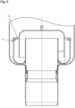
- Fig. 1 the odor trap 1 is shown. In the embodiment shown, it has a standpipe 2, an inner pot 3, a siphon bell 4, a spacer 5 and a sealing element 6.
- the odor trap 1 is inserted into the receiving body 7.
- the receiving body 7 has an outer pot 8 and an outlet nozzle 9.
- the outlet nozzle 9 leads to a sewer system (not shown). All components are round in the present embodiment, which is also illustrated by the symmetry line drawn in. In principle, however, other shapes are also possible, such as an oval or square shape.
- the base 10 of the inner pot 3 has an opening 11 through which the standpipe 2 is inserted. In the area of the opening 11, the standpipe 2 and the base of the inner pot 10 are welded together in a liquid- and gas-tight manner.
- the overflow opening 12 at the upper end of the standpipe 2 is located at approximately the same height as the abutting edge of the side wall 13 of the inner pot 3.
- the side wall 13 delimits a volume that is open upwards and delimited at the bottom by the base 10.
- the siphon bell 4 is positioned so that its side wall 14 is placed between the side wall of the inner pot 13 and the standpipe 13.
- the cover wall 15 of the siphon bell 4 is located above the overflow opening 12. In contrast to the inner pot 3, the siphon bell 4 is thus open downwards.
- the spacer 5 is firmly connected to the siphon bell 4 and rests on the base 10 of the inner pot 3.
- the siphon bell can be lifted up during assembly and for removal using the handle element 17. Once the siphon bell is removed, the odor trap 1 can be easily cleaned.
- the outer pot 8 has an opening 18, to which the outlet nozzle 9 is directly connected flush.
- the standpipe 2 has an expansion 19, which rests on the outer pot 8 and, in an assembled state, defines the vertical position of the odor trap 1 relative to the receiving body 7.
- the odor trap 1 is thus manufactured and mounted in the receiving body 7 such that the standpipe 2 protrudes with a lower end 20 into the outlet nozzle 9.
- the inner pot 3 is welded to the standpipe 2 such that the base 10 has a distance 21 from the outer pot 8 in the vertical direction.
- the outer pot 8 also has a larger diameter than the inner pot 3, so that the inner pot 3 is enclosed by the outer pot 8.
- Below the inner pot 3, the odor trap 1 has a seal 6, which is let into a sealing bead 22 of the standpipe 2.
- the seal is designed as a rolling ring seal and encloses the standpipe 2 so that the circumferential gap between the outlet nozzle 9 and the standpipe 2 is sealed liquid- and gas-tight.
- Liquid that is poured into the receiving body 7 can only enter the sewer system through the standpipe 2 due to the seal 6.
- the cover wall 15 of the siphon bell 4 covers the overflow opening 12, so that the liquid cannot enter the standpipe 2 directly.
- Poured liquid collects in the inner pot 3 when poured in.
- the liquid level exceeds the height of the upper part of the standpipe 2, which protrudes above the base 10 of the inner pot 3.
- the liquid then flows through the overflow opening 12 into the sewer system. If no more liquid is poured in, the part of the liquid that is in the inner pot 3 remains there.
- the liquid still in the inner pot 3 is divided into two areas by the side wall 14 of the siphon bell.
- the first, outer area is in contact with the space above the odor trap 1, is in the outer area of the inner pot 3 and is in contact with the side wall 13 of the inner pot 3.
- the second, inner area is in the inner area of the inner pot 3, which borders the standpipe 2.
- the inner and outer areas are only connected to one another in the area of the gap 16.
- the inner area has no contact with the space above the odor trap 1 because the cover wall 15 of the siphon bell 4 is located above it.
- This accumulation of liquid in the inner pot 3, consisting of an inner and outer area is called a water seal.
- the water seal prevents gas rising from the sewer system from entering the space above the odor trap and instead only collects below the cover wall 15.
- the seal 6 prevents liquid from getting past between the odor trap 1 and the outlet nozzle 9.
- liquid When liquid is poured in, liquid also collects between the outer pot 8 and the inner pot 3. Once the liquid has built up sufficiently, it flows over the side wall 13 into the inner pot 3 and finally through the overflow opening 12 into the sewer system. Even if the seal 6 no longer seals optimally due to age, it still prevents the liquid from flowing past to a greater extent, so that the majority of the liquid flows out via the odor trap 1, renewing the water seal.
- the formation of the water seal is therefore less dependent on the seal being intact in the present embodiment than in conventional odor seals.
- the water seal is also maintained regardless of the condition of the seal.
- Fig. 2 shows a second embodiment, which is characterized by a bow handle 23. This is inserted through holes 24 in the side wall 13. In the figure, it is shown in a stowed position. In this position, the bow handle 23 is folded so that it rests against the side wall 13. Its shape corresponds to the shape of the side wall 13 so that it lies flush. The bow handle 23 can also be set up so that it points upwards in a semicircle. The semicircular part of the bow handle 24 can then simply be grasped to lift the odor trap 1.
- the in Fig. 1 and Fig. 2 The odor traps 1 shown have common properties.
- the floor drain is completely self-draining, which means that the sealing water drains completely when the odor trap 1 is pulled out of the receiving body 7.
- the sealing element 6 for creating gas tightness between the sewer system and the space above it, i.e. between the wastewater side and the factory hall, is located below the sealing water.
- the present construction seals against the inner wall of the outlet nozzle 9, not against the inner wall of the outer pot 8 like conventional solutions. This is a great advantage especially for two-part floor drains because the joint between the outer pot 8 and the outlet nozzle 9 can represent a gas leak between the sewer system and the space above it.
- the odor trap 1 when inserted, holds the sealing water regardless of the condition or presence of the sealing element 6.
Landscapes
- Health & Medical Sciences (AREA)
- Life Sciences & Earth Sciences (AREA)
- Engineering & Computer Science (AREA)
- Hydrology & Water Resources (AREA)
- Public Health (AREA)
- Water Supply & Treatment (AREA)
- Sewage (AREA)
Priority Applications (1)
| Application Number | Priority Date | Filing Date | Title |
|---|---|---|---|
| EP23178274.9A EP4474584A1 (fr) | 2023-06-08 | 2023-06-08 | Siphon à insérer dans un corps de réception doté d'un embout de sortie |
Applications Claiming Priority (1)
| Application Number | Priority Date | Filing Date | Title |
|---|---|---|---|
| EP23178274.9A EP4474584A1 (fr) | 2023-06-08 | 2023-06-08 | Siphon à insérer dans un corps de réception doté d'un embout de sortie |
Publications (1)
| Publication Number | Publication Date |
|---|---|
| EP4474584A1 true EP4474584A1 (fr) | 2024-12-11 |
Family
ID=86732643
Family Applications (1)
| Application Number | Title | Priority Date | Filing Date |
|---|---|---|---|
| EP23178274.9A Pending EP4474584A1 (fr) | 2023-06-08 | 2023-06-08 | Siphon à insérer dans un corps de réception doté d'un embout de sortie |
Country Status (1)
| Country | Link |
|---|---|
| EP (1) | EP4474584A1 (fr) |
Citations (6)
| Publication number | Priority date | Publication date | Assignee | Title |
|---|---|---|---|---|
| CH204114A (de) * | 1938-05-11 | 1939-04-15 | Ernst Fritz | Siphon mit Ölabschluss. |
| EP1229175A2 (fr) * | 2001-01-31 | 2002-08-07 | Franz Viegener II GmbH & Co. KG. | Bouche d'écoulement |
| EP1362961A1 (fr) * | 2002-04-29 | 2003-11-19 | Dallmer GmbH & Co. KG | Elément de construction pour la protection coupe-feu d' un dispositif d' écoulement et dispositif d'écoulement comprenant un tel élement |
| EP1528307A2 (fr) * | 2003-10-24 | 2005-05-04 | Dallmer GmbH & Co. KG | Bouche d'égout avec matière ignifuge |
| EP1627967A1 (fr) * | 2004-08-17 | 2006-02-22 | Dallmer GmbH & Co. KG | Dispositif d'écoulement pour plancher ou plancher intermédiaire |
| DE202018104912U1 (de) | 2018-08-27 | 2019-12-02 | Wiedemann Gmbh | Geruchsverschluss sowie System aus einem Geruchsverschluss und einem Aufnahmekörper |
-
2023
- 2023-06-08 EP EP23178274.9A patent/EP4474584A1/fr active Pending
Patent Citations (6)
| Publication number | Priority date | Publication date | Assignee | Title |
|---|---|---|---|---|
| CH204114A (de) * | 1938-05-11 | 1939-04-15 | Ernst Fritz | Siphon mit Ölabschluss. |
| EP1229175A2 (fr) * | 2001-01-31 | 2002-08-07 | Franz Viegener II GmbH & Co. KG. | Bouche d'écoulement |
| EP1362961A1 (fr) * | 2002-04-29 | 2003-11-19 | Dallmer GmbH & Co. KG | Elément de construction pour la protection coupe-feu d' un dispositif d' écoulement et dispositif d'écoulement comprenant un tel élement |
| EP1528307A2 (fr) * | 2003-10-24 | 2005-05-04 | Dallmer GmbH & Co. KG | Bouche d'égout avec matière ignifuge |
| EP1627967A1 (fr) * | 2004-08-17 | 2006-02-22 | Dallmer GmbH & Co. KG | Dispositif d'écoulement pour plancher ou plancher intermédiaire |
| DE202018104912U1 (de) | 2018-08-27 | 2019-12-02 | Wiedemann Gmbh | Geruchsverschluss sowie System aus einem Geruchsverschluss und einem Aufnahmekörper |
Similar Documents
| Publication | Publication Date | Title |
|---|---|---|
| EP1674629B1 (fr) | Dispositif d'écoulement pour montage à une plaque de plancher avec une ouverture pour eau d'écoulement et ensemble d'un tel dispositif d'écoulement à une plaque de plancher | |
| DE2837967A1 (de) | Wasserablaufbehaelter | |
| DE102011051430B4 (de) | Abwasserablauf mit Geruchsverschluss | |
| EP2046474A1 (fr) | Système de filtre pour fluides | |
| EP2644024A1 (fr) | Dispositif destiné à recevoir un pot de fleur | |
| DE202017100626U1 (de) | System aus einem Geruchsverschluss und einem Aufnahmekörper sowie ein Geruchsverschluss | |
| EP1329562A2 (fr) | Dispositif d'écoulement pour le sol | |
| DE69418455T2 (de) | Vorrichintung für einen abfluss | |
| EP3448732A1 (fr) | Dispositif d'aspiration pour réservoir d'eaux usées | |
| CH632033A5 (en) | Disposable syphon for urinal systems | |
| EP1422354B1 (fr) | Siphon | |
| EP4474584A1 (fr) | Siphon à insérer dans un corps de réception doté d'un embout de sortie | |
| DE102005036576B4 (de) | Ablaufvorrichtung für die Anordnung an einer Bodenplatte mit einer Öffung für Abwasser | |
| DE10201347B4 (de) | Einlaufvorrichtung für die Abführung von Regenwasser von einem Dach | |
| EP4406808B1 (fr) | Plancher pour des aides à la montée | |
| DE20100826U1 (de) | Ablauf mit Geruchsverschluss | |
| EP2573288B1 (fr) | Installation de relèvement d'eaux usées | |
| DE112019001740T5 (de) | Geruchsverschluss | |
| EP4520887B1 (fr) | Bouche d'égout avec piège à odeurs | |
| DE29704565U1 (de) | Vorrichtung zum Filtern von Wasser | |
| DE102011013349A1 (de) | Ablaufvorrichtung für Abwasser | |
| DE102007010774B4 (de) | Anordnung mit einem vertikalen zylindrischen Ablaufrohr | |
| EP1167645B1 (fr) | Dispositif d'entrée dans le sol | |
| EP2573284B1 (fr) | Installation de relèvement d'eaux usées | |
| DE2629527A1 (de) | Geruchsverschluss fuer sanitaer-anlagen, insbesondere fuer urinalanlagen |
Legal Events
| Date | Code | Title | Description |
|---|---|---|---|
| PUAI | Public reference made under article 153(3) epc to a published international application that has entered the european phase |
Free format text: ORIGINAL CODE: 0009012 |
|
| STAA | Information on the status of an ep patent application or granted ep patent |
Free format text: STATUS: THE APPLICATION HAS BEEN PUBLISHED |
|
| AK | Designated contracting states |
Kind code of ref document: A1 Designated state(s): AL AT BE BG CH CY CZ DE DK EE ES FI FR GB GR HR HU IE IS IT LI LT LU LV MC ME MK MT NL NO PL PT RO RS SE SI SK SM TR |
|
| STAA | Information on the status of an ep patent application or granted ep patent |
Free format text: STATUS: REQUEST FOR EXAMINATION WAS MADE |
|
| 17P | Request for examination filed |
Effective date: 20250516 |