EP4474584A1 - Odour trap for insertion into a receiving body with a leaving connection - Google Patents
Odour trap for insertion into a receiving body with a leaving connection Download PDFInfo
- Publication number
- EP4474584A1 EP4474584A1 EP23178274.9A EP23178274A EP4474584A1 EP 4474584 A1 EP4474584 A1 EP 4474584A1 EP 23178274 A EP23178274 A EP 23178274A EP 4474584 A1 EP4474584 A1 EP 4474584A1
- Authority
- EP
- European Patent Office
- Prior art keywords
- standpipe
- inner pot
- side wall
- siphon
- outlet nozzle
- Prior art date
- Legal status (The legal status is an assumption and is not a legal conclusion. Google has not performed a legal analysis and makes no representation as to the accuracy of the status listed.)
- Pending
Links
Images

Classifications
-
- E—FIXED CONSTRUCTIONS
- E03—WATER SUPPLY; SEWERAGE
- E03F—SEWERS; CESSPOOLS
- E03F5/00—Sewerage structures
- E03F5/04—Gullies inlets, road sinks, floor drains with or without odour seals or sediment traps
- E03F5/0407—Floor drains for indoor use
-
- E—FIXED CONSTRUCTIONS
- E03—WATER SUPPLY; SEWERAGE
- E03F—SEWERS; CESSPOOLS
- E03F5/00—Sewerage structures
- E03F5/04—Gullies inlets, road sinks, floor drains with or without odour seals or sediment traps
- E03F2005/0416—Gullies inlets, road sinks, floor drains with or without odour seals or sediment traps with an odour seal
- E03F2005/0418—Gullies inlets, road sinks, floor drains with or without odour seals or sediment traps with an odour seal in the form of a bell siphon
Definitions
- the invention relates to an odor trap for insertion into a receiving body with an outlet nozzle.
- the invention also relates to a system comprising a receiving body and such an odor trap.
- Such an odor trap is used to seal off an outlet nozzle of the receiving body in an odor-tight manner.
- the receiving body can be, for example, a floor drain of a room in a company in the food, chemical or pharmaceutical industry.
- the outlet nozzle of the receiving body can be used to drain liquids from the room, in particular through a drainage channel.
- the liquid to be drained passes through the odor trap that protrudes into the outlet nozzle and reaches a sewer system via the outlet nozzle, for example.
- a water reservoir is usually designed as a water reservoir, for which a siphon insert protrudes into the water reservoir.
- the odor trap prevents gas exchange between the sewer system and the room to be separated. This means that odors from the sewer system cannot enter the room through the outlet nozzle. It is always desirable for an odor trap to have as long a service life as possible.
- DE 20 2018 104 912 U1 describes such an odor trap for insertion into a receiving opening of a receiving body, wherein the odor trap comprises an overflow container with an overflow opening and a siphon insert received in the overflow container and covering the overflow opening, and wherein the overflow container has a handle which is designed to hold the overflow container at an inlet edge of the receiving body delimiting the receiving opening.
- the invention is based on the object of providing an odor trap in which a water seal is created and maintained independently of a seal on the outlet nozzle.
- an odor trap according to claim 1 and by a system comprising an odor trap and a receiving body according to claim 10.
- Advantageous embodiments are the subject of the dependent claims and the description as well as the figures.
- the odor trap according to the invention for insertion into a receiving body with an outlet nozzle comprises a standpipe with an overflow opening at an upper end and with a lower end that protrudes into the outlet nozzle, a siphon bell that covers the upper end of the standpipe with a cover wall and that encloses the standpipe with a side wall, and a sealing element that seals between the outlet nozzle and the standpipe in a gas and liquid-tight manner and is characterized in that an inner pot with a side wall, a base and with an opening in the base through which the standpipe is inserted so that the upper end of the standpipe is above the base of the inner pot, the sealing element is arranged below the inner pot, the side wall of the inner pot encloses the side wall of the siphon bell, a spacer keeps the siphon bell at a distance from the base of the inner pot and the siphon bell forms a water seal with the side wall of the inner pot and the standpipe.
- the system according to the invention comprises an odor trap according to one of the preceding claims and a receiving body which comprises an outlet nozzle and an outer pot, wherein the outer pot comprises a side wall and a base, the base of the outer pot has an opening with which the outlet nozzle is flush, the side wall of the outer pot encloses the side wall of the inner pot and the odor trap rests on the outer pot or the outlet nozzle.
- the odor trap works as follows. Liquid that is poured into the receiving body flows into the inner pot.
- the opening of the inner pot is connected to the standpipe in a liquid-tight manner, so that no liquid can drain out of the inner pot through the opening through which the standpipe is inserted.
- the water flows through the overflow opening of the standpipe into the standpipe and from there into the outlet nozzle of the receiving body.
- the closed siphon bell covers the overflow opening of the standpipe and protrudes with its side walls into the liquid standing in the inner pot.
- the spacer keeps the siphon bell at a distance from the base of the inner pot so that the side walls of the siphon bell do not touch the base of the inner pot.
- the side walls of the siphon bell are so high that in the assembled state in which the siphon bell is inserted into the inner pot, the cover wall of the siphon bell is spaced from the drain opening of the standpipe.
- the liquid can and must flow under the siphon bell until it can drain through the overflow opening.
- the siphon bell divides the liquid in the inner pot into an inner and outer area, with the inner area directly adjacent to the standpipe and covered by the siphon bell, while the outer area is adjacent to the side wall of the inner pot.
- the outer area and the inner area are only connected by one area that has no contact with the liquid surface. These two liquid areas that are connected without surface contact are also called water seals. Gas rising from the sewer system through the standpipe is prevented from escaping by the cover wall of the siphon bell and the water seal. The water seal therefore serves to seal off odors from the sewer system.
- the seal is used to ensure that liquid that is poured into the receiving body actually flows through the inner pot and does not flow past the side between the standpipe and the outlet nozzle. It also ensures that no gas from the sewer system can flow past the side of the standpipe and into the space above the odor trap.
- the seal is not necessarily required to form the water seal. According to the invention, the water seal between the inner pot and the standpipe is retained even if the seal is damaged or no longer functional.
- the receiving body can be shaped so that the uppermost part of the odor trap, usually the cover wall of the siphon bell, is flush with the outer pot of the receiving body, so that the odor trap is installed flush in the floor of the room to be sealed.
- Other designs are also possible that create a geometric relationship between the receiving body, odor trap and the end of the sewer pipe that is appropriate for the purpose.
- the exact connection of the outer pot and outlet nozzle must also be adapted to the specific application and can be designed in different ways. It is usual for the outer pot, outlet nozzle, inner pot, standpipe and siphon bell to be rotationally symmetrical.
- the inner pot and the standpipe form a unit that corresponds to the overflow container of a conventional odor trap. Due to the inventive division of a one-piece overflow container, such as that found in odor traps of the type described above, into an inner pot and a standpipe, the standpipe can extend into the outlet nozzle without the inner pot being in the outlet nozzle. The water reservoir that forms in the inner pot can thus be arranged above the seal. According to the invention, liquid poured into the receiving body always flows through the inner pot and then through the standpipe to get into the sewer. Even if the seal no longer seals properly due to ageing of the material or damage, a large proportion of the liquid still gets through the odor trap into the sewer, with the water seal constantly being renewed.
- the water seal is also maintained regardless of the condition of the seal between the inner pot and the standpipe.
- the seal is therefore no longer needed for the water seal to form and remain so, meaning that the odor trap has a longer service life.
- This is particularly advantageous compared to conventional odor traps that do not have an inner pot and where the water seal is formed between the standpipe and a wall of the receiving opening that surrounds the standpipe. It can be assumed that even an ageing seal still has an adequate sealing effect against gas rising from the sewer, even if it is no longer completely liquid-tight.
- the inner pot and standpipe can be made from two individual parts that are then joined together. By dividing them into two separate components, these two individual components can be manufactured particularly easily.
- the sealing element is a rolling ring.
- a rolling ring seal is inexpensive and offers good sealing properties. In comparison to other seals, such as lip seals, rolling ring seals also seal when the standpipe is not exactly aligned in the outlet support. Even if it is tilted, the rolling ring seal fits snugly against the standpipe and the outlet support to ensure sealing. Using a rolling ring seal also allows the odor trap to be installed particularly easily in the receiving body.
- the standpipe has a circumferential recess on the outside in which the rolling ring is located.
- the sealing ring can be pre-assembled on the standpipe and inserted into the receiving body together with the odor trap.
- the recess therefore makes assembly easier.
- the recess ensures that the Sealing ring sits securely and cannot slip down into the outlet nozzle during operation.
- the recess is usually referred to as a sealing bead.
- the inner pot does not touch the receiving body. If both the outer pot and the inner pot are made of metal, metal-to-metal contact is prevented. Such metal-to-metal contact can lead to accelerated wear and should therefore be avoided. In particular, such contact promotes corrosion.
- the base of the inner pot is welded to the standpipe. Welding allows the use of simply shaped sheet metal parts, so that favorable manufacturing properties and thus low manufacturing costs are achieved. Furthermore, welding is both easy to handle and inexpensive.
- the siphon bell has a handle element with which the siphon element can be removed from the odor trap.
- the handle element allows the siphon bell to be easily lifted. This enables both easy assembly and disassembly. In addition, the simple disassembly makes it easy to remove the siphon bell for cleaning.
- the standpipe has a widening which is located between the sealing element and the inner pot and with which the standpipe rests on the receiving body.
- the widening represents an area of the standpipe whose diameter is larger than the diameter of the area which protrudes into the outlet nozzle. The diameter is in particular larger than that of the outlet nozzle.
- the expansion also makes the defined assembly easy.
- such an expansion of the standpipe is easy to manufacture, so that the vertical positioning to be achieved is associated with only low production costs.
- the expansion can cover the entire circumference, so that a certain sealing effect is achieved simply by the contact as a result of the standpipe resting on the receiving body with the expansion. This sealing effect supports the inventive aim of decoupling the provision of a seal against odors from the sewer system from the condition of the seal to a greater extent than has previously been the case in the prior art.
- the spacer is formed by at least two metal sheets that are firmly connected to the siphon, that are arranged between the inner pot and the siphon, that extend in the vertical direction and that are distributed over the circumference of the side wall of the siphon.
- the siphon bell In order to form the water seal, the siphon bell must not rest with the abutting edge of its side edges on the bottom of the inner pot. Otherwise, liquid could not get from the inner pot to the overflow opening and liquid could therefore not drain through the odor trap.
- the metal sheets must be of an appropriate size and distributed over the circumference of the siphon bell. In order to impede the flow as little as possible during drainage, at least two vertically extending metal sheets can be used that are connected to the siphon bell.
- the sheets are not made of metal either.
- sheet simply refers to a flat, planar element with two main directions of expansion.
- the spacer is formed by three sheets that extend in a radial direction and that rest against the standpipe with their inner abutting edges.
- the radial extension of the sheets enables favorable Flow characteristics that allow liquid poured in to drain quickly, flowing from the outside to the inside. This has a positive effect on the odor trap's absorption capacity.
- the internal abutting edges of the sheets also ensure that the siphon bell is centered in the radial direction relative to the inner pot and the standpipe. This prevents the siphon bell from having unwanted contact with the inner areas of the side walls of the inner pot in one area.
- the centering also makes it much easier to position the siphon bell during assembly.
- the precise assembly means that appropriate planning and favorable drainage characteristics can be provided during construction.
- Fig. 1 the odor trap 1 is shown. In the embodiment shown, it has a standpipe 2, an inner pot 3, a siphon bell 4, a spacer 5 and a sealing element 6.
- the odor trap 1 is inserted into the receiving body 7.
- the receiving body 7 has an outer pot 8 and an outlet nozzle 9.
- the outlet nozzle 9 leads to a sewer system (not shown). All components are round in the present embodiment, which is also illustrated by the symmetry line drawn in. In principle, however, other shapes are also possible, such as an oval or square shape.
- the base 10 of the inner pot 3 has an opening 11 through which the standpipe 2 is inserted. In the area of the opening 11, the standpipe 2 and the base of the inner pot 10 are welded together in a liquid- and gas-tight manner.
- the overflow opening 12 at the upper end of the standpipe 2 is located at approximately the same height as the abutting edge of the side wall 13 of the inner pot 3.
- the side wall 13 delimits a volume that is open upwards and delimited at the bottom by the base 10.
- the siphon bell 4 is positioned so that its side wall 14 is placed between the side wall of the inner pot 13 and the standpipe 13.
- the cover wall 15 of the siphon bell 4 is located above the overflow opening 12. In contrast to the inner pot 3, the siphon bell 4 is thus open downwards.
- the spacer 5 is firmly connected to the siphon bell 4 and rests on the base 10 of the inner pot 3.
- the siphon bell can be lifted up during assembly and for removal using the handle element 17. Once the siphon bell is removed, the odor trap 1 can be easily cleaned.
- the outer pot 8 has an opening 18, to which the outlet nozzle 9 is directly connected flush.
- the standpipe 2 has an expansion 19, which rests on the outer pot 8 and, in an assembled state, defines the vertical position of the odor trap 1 relative to the receiving body 7.
- the odor trap 1 is thus manufactured and mounted in the receiving body 7 such that the standpipe 2 protrudes with a lower end 20 into the outlet nozzle 9.
- the inner pot 3 is welded to the standpipe 2 such that the base 10 has a distance 21 from the outer pot 8 in the vertical direction.
- the outer pot 8 also has a larger diameter than the inner pot 3, so that the inner pot 3 is enclosed by the outer pot 8.
- Below the inner pot 3, the odor trap 1 has a seal 6, which is let into a sealing bead 22 of the standpipe 2.
- the seal is designed as a rolling ring seal and encloses the standpipe 2 so that the circumferential gap between the outlet nozzle 9 and the standpipe 2 is sealed liquid- and gas-tight.
- Liquid that is poured into the receiving body 7 can only enter the sewer system through the standpipe 2 due to the seal 6.
- the cover wall 15 of the siphon bell 4 covers the overflow opening 12, so that the liquid cannot enter the standpipe 2 directly.
- Poured liquid collects in the inner pot 3 when poured in.
- the liquid level exceeds the height of the upper part of the standpipe 2, which protrudes above the base 10 of the inner pot 3.
- the liquid then flows through the overflow opening 12 into the sewer system. If no more liquid is poured in, the part of the liquid that is in the inner pot 3 remains there.
- the liquid still in the inner pot 3 is divided into two areas by the side wall 14 of the siphon bell.
- the first, outer area is in contact with the space above the odor trap 1, is in the outer area of the inner pot 3 and is in contact with the side wall 13 of the inner pot 3.
- the second, inner area is in the inner area of the inner pot 3, which borders the standpipe 2.
- the inner and outer areas are only connected to one another in the area of the gap 16.
- the inner area has no contact with the space above the odor trap 1 because the cover wall 15 of the siphon bell 4 is located above it.
- This accumulation of liquid in the inner pot 3, consisting of an inner and outer area is called a water seal.
- the water seal prevents gas rising from the sewer system from entering the space above the odor trap and instead only collects below the cover wall 15.
- the seal 6 prevents liquid from getting past between the odor trap 1 and the outlet nozzle 9.
- liquid When liquid is poured in, liquid also collects between the outer pot 8 and the inner pot 3. Once the liquid has built up sufficiently, it flows over the side wall 13 into the inner pot 3 and finally through the overflow opening 12 into the sewer system. Even if the seal 6 no longer seals optimally due to age, it still prevents the liquid from flowing past to a greater extent, so that the majority of the liquid flows out via the odor trap 1, renewing the water seal.
- the formation of the water seal is therefore less dependent on the seal being intact in the present embodiment than in conventional odor seals.
- the water seal is also maintained regardless of the condition of the seal.
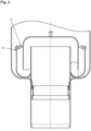
- Fig. 2 shows a second embodiment, which is characterized by a bow handle 23. This is inserted through holes 24 in the side wall 13. In the figure, it is shown in a stowed position. In this position, the bow handle 23 is folded so that it rests against the side wall 13. Its shape corresponds to the shape of the side wall 13 so that it lies flush. The bow handle 23 can also be set up so that it points upwards in a semicircle. The semicircular part of the bow handle 24 can then simply be grasped to lift the odor trap 1.
- the in Fig. 1 and Fig. 2 The odor traps 1 shown have common properties.
- the floor drain is completely self-draining, which means that the sealing water drains completely when the odor trap 1 is pulled out of the receiving body 7.
- the sealing element 6 for creating gas tightness between the sewer system and the space above it, i.e. between the wastewater side and the factory hall, is located below the sealing water.
- the present construction seals against the inner wall of the outlet nozzle 9, not against the inner wall of the outer pot 8 like conventional solutions. This is a great advantage especially for two-part floor drains because the joint between the outer pot 8 and the outlet nozzle 9 can represent a gas leak between the sewer system and the space above it.
- the odor trap 1 when inserted, holds the sealing water regardless of the condition or presence of the sealing element 6.
Landscapes
- Health & Medical Sciences (AREA)
- Life Sciences & Earth Sciences (AREA)
- Engineering & Computer Science (AREA)
- Hydrology & Water Resources (AREA)
- Public Health (AREA)
- Water Supply & Treatment (AREA)
- Sewage (AREA)
Abstract
Geruchsverschluss zum Einsetzen in einen Aufnahmekörper mit einem Abgangsstutzen umfassend ein Standrohr mit einer Überlauföffnung an einem oberen Ende und mit einem unter Ende, das in den Abgangsstutzen ragt, eine Siphonglocke, die mit einer Deckelwand das obere Ende des Standrohrs überdeckt und die mit einer Seitenwand das Standrohr umfasst, ein Dichtelement, das zwischen Abgangsstutzen und Standrohr gas- und flüßigkeits-dichtend abschließt, dadurch gekennzeichnet, dass ein Innentopf mit einer Seitenwand, einem Grund und mit einer Öffnung in dem Grund, durch die das Standrohr so gesteckt ist, dass sich das obere Ende des Standrohrs oberhalb des Grundes des Innentopfs befindet, vorhanden ist, das Dichtelement unterhalb des Innentopfes angeordnet ist, die Seitenwand des Innentopfs die Seitenwand der Siphonglocke umfasst, ein Abstandhalter die Siphonglocke in einem Abstand zu dem Grund des Innentopfs hält und die Siphonglocke eine Wasservorlage mit der Seitenwand des Innentopfs und dem Standrohr bildet.Odor trap for insertion into a receiving body with an outlet nozzle, comprising a standpipe with an overflow opening at an upper end and with a lower end that projects into the outlet nozzle, a siphon bell that covers the upper end of the standpipe with a cover wall and that encloses the standpipe with a side wall, a sealing element that seals between the outlet nozzle and the standpipe in a gas- and liquid-tight manner, characterized in that there is an inner pot with a side wall, a base and with an opening in the base through which the standpipe is inserted such that the upper end of the standpipe is above the base of the inner pot, the sealing element is arranged below the inner pot, the side wall of the inner pot encloses the side wall of the siphon bell, a spacer keeps the siphon bell at a distance from the base of the inner pot, and the siphon bell forms a water seal with the side wall of the inner pot and the standpipe.
Description
Die Erfindung betrifft einen Geruchsverschluss zum Einsetzen in einen Aufnahmekörper mit einem Abgangsstutzen. Zudem betrifft die Erfindung ein System aus einem Aufnahmekörper und einem solchen Geruchsverschluss.The invention relates to an odor trap for insertion into a receiving body with an outlet nozzle. The invention also relates to a system comprising a receiving body and such an odor trap.
Ein derartiger Geruchsverschluss dient dem geruchsdichten Verschließen eines Abgangsstutzens des Aufnahmekörpers. Der Aufnahmekörper kann beispielsweise ein Bodeneinlauf eines Raumes in einem Betrieb der Nahrungsmittel-, chemischen oder pharmazeutischen Industrie sein. Der Abgangsstutzen des Aufnahmekörpers kann dem Abführen von Flüssigkeiten aus dem Raum insbesondere durch eine Entwässerungsrinne dienen. Die abzuführende Flüssigkeit durchläuft den in den Abgangsstutzen ragenden Geruchsverschluss und gelangt über den Abgangsstutzen zum Beispiel in eine Kanalisation. Bei derartigen Geruchsverschlüssen ist üblicherweise ein Wasserreservoir als Wasservorlage ausgebildet, wozu ein Siphoneinsatz in das Wasserreservoir hineinragt. Der Geruchsverschluss verhindert einen Gasaustausch zwischen der Kanalisation und dem abzutrennenden Raum. So können Gerüche aus der Kanalisation nicht durch den Abgangsstutzen in den Raum gelangen. Es ist stets wünschenswert, dass ein Geruchsverschluss eine möglichst lange Lebensdauer aufweist.Such an odor trap is used to seal off an outlet nozzle of the receiving body in an odor-tight manner. The receiving body can be, for example, a floor drain of a room in a company in the food, chemical or pharmaceutical industry. The outlet nozzle of the receiving body can be used to drain liquids from the room, in particular through a drainage channel. The liquid to be drained passes through the odor trap that protrudes into the outlet nozzle and reaches a sewer system via the outlet nozzle, for example. In such odor traps, a water reservoir is usually designed as a water reservoir, for which a siphon insert protrudes into the water reservoir. The odor trap prevents gas exchange between the sewer system and the room to be separated. This means that odors from the sewer system cannot enter the room through the outlet nozzle. It is always desirable for an odor trap to have as long a service life as possible.
Bei üblichen Geruchsverschlüssen wird zur Bildung des Wasserreservoirs eine Dichtung zwischen Abgangsstutzen und Geruchsverschluss benötigt, um das Wasserreservoir zu bilden.With conventional odor traps, a seal is required between the outlet nozzle and the odor trap to form the water reservoir.
Der Erfindung liegt ausgehend vom erläuterten Stand der Technik die Aufgabe zugrunde, einen Geruchsverschluss zur Verfügung zu stellen, bei dem eine Wasservorlage unabhängig von einer Abdichtung des Abgangsstutzens entsteht und erhalten bleibt.Based on the prior art explained, the invention is based on the object of providing an odor trap in which a water seal is created and maintained independently of a seal on the outlet nozzle.
Erfindungsgemäß wird die Aufgabe gelöst durch einen Geruchsverschluss gemäß Anspruch 1 sowie durch ein System aus einem Geruchsverschluss und einem Aufnahmekörper gemäß Anspruch 10. Vorteilhafte Ausgestaltungen sind Gegenstand der abhängigen Ansprüche und der Beschreibung sowie der Figuren.According to the invention, the object is achieved by an odor trap according to
Die folgende Beschreibung und die Ansprüche beziehen sich, sofern keine anderslautenden Informationen angegeben sind, auf einen zusammengebauten Zustand, bei dem die Einzelteile des Geruchsverschlusses zusammengesetzt und in den Aufnahmekörper eingesetzt sind. Dabei beziehen sich auch Orts- und Richtungsangaben wie bspw. "oben", "unten", "vertikal", "horizontal", "innen", "außen", "radial" usw. auf diesen zusammengebauten Zustand, wobei sich die Kanalisation unten befindet, die vertikale Richtung von oben nach unten verläuft, eine vertikale Symmetrieachse des Geruchsverschlusses innen liegt und die radiale Richtung senkrecht zu der Symmetrieachse von innen nach außen zeigt.The following description and claims refer, unless otherwise stated, to an assembled state in which the individual parts of the odor trap are assembled and inserted into the receiving body. Location and direction information such as "top", "bottom", "vertical", "horizontal", "inside", "outside", "radial" etc. also refer to this assembled state, with the sewerage system located at the bottom, the vertical direction running from top to bottom, a vertical axis of symmetry of the odor trap is inside and the radial direction perpendicular to the axis of symmetry points from inside to outside.
Der erfindungsgemäße Geruchsverschluss zum Einsetzen in einen Aufnahmekörper mit einem Abgangsstutzen umfasst ein Standrohr mit einer Überlauföffnung an einem oberen Ende und mit einem unter Ende, das in den Abgangsstutzen ragt, eine Siphonglocke, die mit einer Deckelwand das obere Ende des Standrohrs überdeckt und die mit einer Seitenwand das Standrohr umfasst, sowie ein Dichtelement, das zwischen Abgangsstutzen und Standrohr gas- und flüßigkeits-dichtend abschließt und ist dadurch gekennzeichnet, dass ein Innentopf mit einer Seitenwand, einem Grund und mit einer Öffnung in dem Grund, durch die das Standrohr so gesteckt ist, dass sich das obere Ende des Standrohrs oberhalb des Grundes des Innentopfs befindet, vorhanden ist, das Dichtelement unterhalb des Innentopfes angeordnet ist, die Seitenwand des Innentopfs die Seitenwand der Siphonglocke umfasst, ein Abstandhalter die Siphonglocke in einem Abstand zu dem Grund des Innentopfs hält und die Siphonglocke eine Wasservorlage mit der Seitenwand des Innentopfs und dem Standrohr bildet.The odor trap according to the invention for insertion into a receiving body with an outlet nozzle comprises a standpipe with an overflow opening at an upper end and with a lower end that protrudes into the outlet nozzle, a siphon bell that covers the upper end of the standpipe with a cover wall and that encloses the standpipe with a side wall, and a sealing element that seals between the outlet nozzle and the standpipe in a gas and liquid-tight manner and is characterized in that an inner pot with a side wall, a base and with an opening in the base through which the standpipe is inserted so that the upper end of the standpipe is above the base of the inner pot, the sealing element is arranged below the inner pot, the side wall of the inner pot encloses the side wall of the siphon bell, a spacer keeps the siphon bell at a distance from the base of the inner pot and the siphon bell forms a water seal with the side wall of the inner pot and the standpipe.
Das erfindungsgemäße System umfasst einen Geruchsverschluss nach einem der vorhergehenden Ansprüche und einen Aufnahmekörper, der einen Abgangsstutzen und einen Außentopf umfasst, wobei der Außentopf eine Seitenwand und einen Grund umfasst, der Grund des Außentopfs eine Öffnung aufweist mit der der Abgangsstutzen bündig abschließt, die Seitenwand des Außentopfs die Seitenwand des Innentopfs umschließt und der Geruchsverschluss auf dem Außentopf oder dem Abgangsstutzen aufliegt.The system according to the invention comprises an odor trap according to one of the preceding claims and a receiving body which comprises an outlet nozzle and an outer pot, wherein the outer pot comprises a side wall and a base, the base of the outer pot has an opening with which the outlet nozzle is flush, the side wall of the outer pot encloses the side wall of the inner pot and the odor trap rests on the outer pot or the outlet nozzle.
Der Geruchsverschluss funktioniert folgendermaßen. Flüssigkeit, die in den Aufnahmekörper geschüttet wird, fließt in den Innentopf. Die Öffnung des Innentopfs ist mit dem Standrohr flüssigkeitsdicht verbunden, sodass aus der Öffnung, durch die das Standrohr gesteckt ist, keine Flüssigkeit aus dem Innentopf ablaufen kann. Sobald sich im Innentopf so viel Flüssigkeit angesammelt hat, dass die Flüssigkeit höher reicht als das obere Ende des Standrohrs, fließt das Wasser durch die Überlauföffnung des Standrohrs in das Standrohr und von dort in den Abgangsstutzen des Aufnahmekörpers. Die geschlossene Siphonglocke deckt die Überlauföffnung des Standrohrs ab und ragt mit ihren Seitenwänden in im Innenstopf stehende Flüssigkeit. Dabei hält der Abstandhalter die Siphonglocke in einem Abstand zum Grund des Innentopfs, sodass die Seitenwände der Siphonglocke den Grund des Innentopfes nicht berühren. Die Seitenwände der Siphonglocke sind so hoch, dass in dem zusammengebauten Zustand, in dem die Siphonglocke in den Innentopf eingesetzt ist, die Deckelwand der Siphonglocke von der Abflussöffnung des Standrohres beabstandet ist. Die Flüssigkeit kann und muss, bis sie durch die Überlauföffnung abfließen kann, unter der Siphonglocke hindurchströmen. Die Siphonglocke unterteilt im Innentopf befindliche Flüssigkeit in einen inneren und äußeren Bereich, wobei der innere Bereich direkt an das Standrohr angrenzt und durch die Siphonglocke überdeckt ist, während der äußere Bereich an die Seitenwand des Innentopfs angrenzt. Der äußere Bereich und der innere Bereich sind nur durch einen Bereich verbunden, der keinen Kontakt zur Flüssigkeitsoberfläche hat. Diese beiden, ohne Oberflächenkontakt verbundenen Flüssigkeits-Bereiche werden auch Wasservorlage genannt. Durch das Standrohr aufsteigendes Gas aus der Kanalisation wird durch die Deckelwand der Siphonglocke und die Wasservorlage am Ausströmen gehindert. Die Wasservorlage dient folglich dazu, dass ein Abschluss gegen Gerüche aus der Kanalisation vorliegt.The odor trap works as follows. Liquid that is poured into the receiving body flows into the inner pot. The opening of the inner pot is connected to the standpipe in a liquid-tight manner, so that no liquid can drain out of the inner pot through the opening through which the standpipe is inserted. As soon as so much liquid has collected in the inner pot that the liquid reaches higher than the upper end of the standpipe, the water flows through the overflow opening of the standpipe into the standpipe and from there into the outlet nozzle of the receiving body. The closed siphon bell covers the overflow opening of the standpipe and protrudes with its side walls into the liquid standing in the inner pot. The spacer keeps the siphon bell at a distance from the base of the inner pot so that the side walls of the siphon bell do not touch the base of the inner pot. The side walls of the siphon bell are so high that in the assembled state in which the siphon bell is inserted into the inner pot, the cover wall of the siphon bell is spaced from the drain opening of the standpipe. The liquid can and must flow under the siphon bell until it can drain through the overflow opening. The siphon bell divides the liquid in the inner pot into an inner and outer area, with the inner area directly adjacent to the standpipe and covered by the siphon bell, while the outer area is adjacent to the side wall of the inner pot. The outer area and the inner area are only connected by one area that has no contact with the liquid surface. These two liquid areas that are connected without surface contact are also called water seals. Gas rising from the sewer system through the standpipe is prevented from escaping by the cover wall of the siphon bell and the water seal. The water seal therefore serves to seal off odors from the sewer system.
Die Dichtung dient dazu, dass Flüssigkeit welche in den Aufnahmekörper geschüttet wird, auch tatsächlich durch den Innentopf abfließt und nicht seitlich zwischen Standrohr und Abgangsstutzen vorbeifließt. Außerdem sorgt sie dafür, dass kein Gas aus der Kanalisation seitlich an dem Standrohr vorbeiströmen kann und in den Raum oberhalb des Geruchsverschlusses gelangt. Die Dichtung wird hingegen nicht zwangsläufig benötigt, um die Wasservorlage zu bilden. Erfindungsgemäß bleibt die Wasservorlage zwischen Innentopf und Standrohr auch erhalten, wenn die Dichtung beschädigt oder nicht mehr funktionsfähig ist.The seal is used to ensure that liquid that is poured into the receiving body actually flows through the inner pot and does not flow past the side between the standpipe and the outlet nozzle. It also ensures that no gas from the sewer system can flow past the side of the standpipe and into the space above the odor trap. The seal, however, is not necessarily required to form the water seal. According to the invention, the water seal between the inner pot and the standpipe is retained even if the seal is damaged or no longer functional.
Der Aufnahmekörper kann so ausgeformt sein, dass der oberste Teil des Geruchsverschlusses, üblicherweise die Deckelwand der Siphonglocke, bündig mit dem Außentopf des Aufnahmekörpers abschließt, sodass der Geruchsverschluss eben im Boden des abzuschließenden Raums eingebracht ist. Auch andere Ausführungsformen sind möglich, die eine dem Zweck angemessene geometrische Beziehung zwischen Aufnahmekörper, Geruchsverschluss und Rohrende der Kanalisation bilden. Auch die genaue Anbindung von Außentopf und Abgangsstutzen ist der spezifischen Anwendung anzupassen und kann verschieden ausgebildet sein. Dabei ist es üblich, dass Außentopf, Abgangsstutzen, Innentopf, Standrohr und Siphonglocke rotationssymmetrisch ausgebildet sind.The receiving body can be shaped so that the uppermost part of the odor trap, usually the cover wall of the siphon bell, is flush with the outer pot of the receiving body, so that the odor trap is installed flush in the floor of the room to be sealed. Other designs are also possible that create a geometric relationship between the receiving body, odor trap and the end of the sewer pipe that is appropriate for the purpose. The exact connection of the outer pot and outlet nozzle must also be adapted to the specific application and can be designed in different ways. It is usual for the outer pot, outlet nozzle, inner pot, standpipe and siphon bell to be rotationally symmetrical.
Erfindungsgemäß bilden der Innentopf und das Standrohr eine Einheit, die dem Überlaufbehälter eines konventionellen Geruchsverschlusses entspricht. Durch die erfindungsgemäße Aufteilung eines einteiligen Überlaufbehälters, wie ihn Geruchsverschlüssen nach der eingangs geschilderten Bauart aufweisen, in Innentopf und Standrohr kann das Standrohr in den Abgangsstutzen ragen, ohne dass sich der Innentopf im Abgangsstutzen befindet. Die sich im Innentopf bildende Wasservorlage kann so oberhalb der Dichtung angeordnet sein. In den Aufnahmekörper geschüttete Flüssigkeit fließt erfindungsgemäß immer durch den Innentopf und anschließend durch das Standrohr, um in die Kanalisation zu gelangen. Auch wenn die Dichtung aufgrund von Material alterung oder einer Beschädigung nicht mehr ordentlich dichtet, gelangt trotzdem ein Großteil der Flüssigkeit durch den Geruchsverschluss in die Kanalisation, wobei sich die Wasservorlage immer wieder erneuert. Auch bleibt die Wasservorlage unabhängig vom Zustand der Dichtung zwischen Innentopf und Standrohr erhalten. Die Dichtung wird folglich nicht mehr dazu benötigt, dass sich die Wasservorlage bilden kann und erhalten bleibt, sodass der Geruchsverschluss eine höhere Lebensdauer aufweist. Das ist besonders gegenüber solchen konventionellen Geruchsabschlüssen vorteilhaft, die über keinen Innentopf verfügen und bei denen die Wasservorlage zwischen dem Standrohr und einer Wand der Aufnahmeöffnung, die das Standrohr umgibt, ausgebildet ist. Dabei ist davon auszugehen, dass selbst eine alternde Dichtung immer noch eine ausreichende Dichtwirkung gegenüber aus der Kanalisation aufsteigendem Gas aufweist, selbst wenn sie nicht mehr vollständig flüssigkeitsabdichtend ist.According to the invention, the inner pot and the standpipe form a unit that corresponds to the overflow container of a conventional odor trap. Due to the inventive division of a one-piece overflow container, such as that found in odor traps of the type described above, into an inner pot and a standpipe, the standpipe can extend into the outlet nozzle without the inner pot being in the outlet nozzle. The water reservoir that forms in the inner pot can thus be arranged above the seal. According to the invention, liquid poured into the receiving body always flows through the inner pot and then through the standpipe to get into the sewer. Even if the seal no longer seals properly due to ageing of the material or damage, a large proportion of the liquid still gets through the odor trap into the sewer, with the water seal constantly being renewed. The water seal is also maintained regardless of the condition of the seal between the inner pot and the standpipe. The seal is therefore no longer needed for the water seal to form and remain so, meaning that the odor trap has a longer service life. This is particularly advantageous compared to conventional odor traps that do not have an inner pot and where the water seal is formed between the standpipe and a wall of the receiving opening that surrounds the standpipe. It can be assumed that even an ageing seal still has an adequate sealing effect against gas rising from the sewer, even if it is no longer completely liquid-tight.
Insbesondere können Innentopf und Standrohr aus zwei einzelnen Teilen gefertigt sein, die anschließend gefügt werden. Durch die Aufteilung in zwei separate Bauteile können diese beiden einzelnen Bauteile besonders einfach gefertigt werden.In particular, the inner pot and standpipe can be made from two individual parts that are then joined together. By dividing them into two separate components, these two individual components can be manufactured particularly easily.
Nach einer Ausgestaltung ist das Dichtelement ein Rollring. Eine Rollring-Dichtung ist günstig und bietet günstige Dichteigenschaften. Im Vergleich zu anderen Dichtungen, wie bspw. Lippendichtungen, dichten Rollring-Dichtungen auch, wenn das Standrohr nicht exakt in dem Abgangsstützen ausgerichtet ist. Auch bei einer Verkippung liegt die Rollring-Dichtung umfassend an dem Standrohr und an dem Abgangsstutzen an, um so die Abdichtung zu gewährleisten. Eine Rollring-Dichtung zu verwenden, erlaubt auch eine besonders einfache Montage des Geruchsverschlusses in dem Aufnahmekörper.According to one design, the sealing element is a rolling ring. A rolling ring seal is inexpensive and offers good sealing properties. In comparison to other seals, such as lip seals, rolling ring seals also seal when the standpipe is not exactly aligned in the outlet support. Even if it is tilted, the rolling ring seal fits snugly against the standpipe and the outlet support to ensure sealing. Using a rolling ring seal also allows the odor trap to be installed particularly easily in the receiving body.
Nach einer Ausgestaltung weist das Standrohr auf einer Außenseite eine umlaufende Vertiefung auf, in der sich der Rollring befindet. Durch das Aufbringen der Vertiefung kann der Dichtring auf dem Standrohr vormontiert werden und zusammen mit dem Geruchsverschluss in den Aufnahmekörper eingesetzt werden. Die Vertiefung erleichtert folglich die Montage. Weiterhin sorgt die Vertiefung dafür, dass der Dichtungsring sicher sitzt und auch im Betrieb nicht nach unten in den Abgangsstutzen rutschen kann. Üblicherweise wird die Vertiefung als Dichtsicke bezeichnet.According to one design, the standpipe has a circumferential recess on the outside in which the rolling ring is located. By applying the recess, the sealing ring can be pre-assembled on the standpipe and inserted into the receiving body together with the odor trap. The recess therefore makes assembly easier. Furthermore, the recess ensures that the Sealing ring sits securely and cannot slip down into the outlet nozzle during operation. The recess is usually referred to as a sealing bead.
Nach einer Ausgestaltung berührt der Innentopf den Aufnahmekörper nicht. Sofern sowohl der Außentopf als auch der Innentopf aus Metall gefertigt sind, wird ein Kontakt von Metall auf Metall verhindert. Ein solcher Metall-zu-Metall-Kontakt kann zu einer beschleunigten Abnutzung führen und ist daher zu vermeiden. Insbesondere fördert ein solcher Kontakt Korrosion.According to one design, the inner pot does not touch the receiving body. If both the outer pot and the inner pot are made of metal, metal-to-metal contact is prevented. Such metal-to-metal contact can lead to accelerated wear and should therefore be avoided. In particular, such contact promotes corrosion.
Nach einer Ausgestaltung ist der Grund des Innentopfs an das Standrohr angeschweißt. Anschweißen erlaubt den Einsatz einfach geformter Blechteile, sodass günstige Fertigungseigenschaften und somit geringe Fertigungskosten erzielt werden. Weiterhin ist Schweißen sowohl einfach handzuhaben als auch günstig.According to one design, the base of the inner pot is welded to the standpipe. Welding allows the use of simply shaped sheet metal parts, so that favorable manufacturing properties and thus low manufacturing costs are achieved. Furthermore, welding is both easy to handle and inexpensive.
Nach einer Ausgestaltung weist die Siphonglocke ein Griffelement auf, mit der das Siphonelement von dem Geruchsverschluss abnehmbar ist. Das Griffelement erlaubt ein einfaches Anheben der Siphonglocke. Das ermöglich sowohl eine einfache Montage als auch eine einfache Demontage. Außerdem ist es durch die einfache Demontage problemlos möglich, die Siphonglocke zur Reinigung abzunehmen.According to one design, the siphon bell has a handle element with which the siphon element can be removed from the odor trap. The handle element allows the siphon bell to be easily lifted. This enables both easy assembly and disassembly. In addition, the simple disassembly makes it easy to remove the siphon bell for cleaning.
Nach einer Ausgestaltung weist das Standrohr eine Aufweitung auf, die sich zwischen dem Dichtelement und dem Innentopf befindet, und mit der das Standrohr auf dem Aufnahmekörper aufliegt. Die Aufweitung stellt einen Bereich des Standrohres dar, dessen Durchmesser größer ist als der Durchmesser des Bereiches, der in den Abgangsstutzen ragt. Der Durchmesser ist insbesondere größer als der des Abgangsstutzens. Der Geruchsverschluss liegt, wenn das untere Ende des Standrohres in den Abgangsstutzen gesteckt ist, mit der Aufweitung auf dem Abgangsstutzen oder auf dem Aufnahmekörper auf. Die Aufweitung definiert dadurch eine vertikale Lage des Geruchsverschlusses relativ zu dem Aufnahmekörper in dem zusammengebauten Zustand. Auf diese Weise ist klar definiert, wo das untere Ende des Standrohres ist, das in den Abgangsstutzen ragt. Dadurch wird insbesondere eine Positionierung der Dichtung und des Innentopfs bei der Konstruktion erleichtert, um die vorteilhafte Positionierung der Wasservorlage oberhalb der Dichtung zu ermöglichen.According to one embodiment, the standpipe has a widening which is located between the sealing element and the inner pot and with which the standpipe rests on the receiving body. The widening represents an area of the standpipe whose diameter is larger than the diameter of the area which protrudes into the outlet nozzle. The diameter is in particular larger than that of the outlet nozzle. When the lower end of the standpipe is inserted into the outlet nozzle, the odor trap rests with the widening on the outlet nozzle or on the receiving body. The widening thus defines a vertical position of the odor trap relative to the receiving body in the assembled state. In this way, it is clearly defined where the lower end of the standpipe is which protrudes into the outlet nozzle. This in particular enables the positioning of the Seal and the inner pot were made easier during construction to enable the advantageous positioning of the water reservoir above the seal.
Auch die definierte Montage ist durch die Aufweitung einfach. Darüber hinaus ist eine solche Aufweitung des Standrohres einfach zu fertigen, sodass die zu erzielende vertikale Positionierung nur mit geringen Fertigungskosten verbunden ist. Weiterhin kann die Aufweitung den gesamten Umfang abdecken, sodass alleine durch die Berührung infolge des Aufliegens des Standrohres auf dem Aufnahmekörper mit der Aufweitung eine gewisse Dichtwirkung erzielt wird. Diese Dichtwirkung unterstützt das erfindungsgemäße Ziel, die Bereitstellung eines Abschlusses von Gerüchen aus der Kanalisation von dem Zustand der Dichtung stärker zu entkoppeln als bisher im Stand der Technik üblich.The expansion also makes the defined assembly easy. In addition, such an expansion of the standpipe is easy to manufacture, so that the vertical positioning to be achieved is associated with only low production costs. Furthermore, the expansion can cover the entire circumference, so that a certain sealing effect is achieved simply by the contact as a result of the standpipe resting on the receiving body with the expansion. This sealing effect supports the inventive aim of decoupling the provision of a seal against odors from the sewer system from the condition of the seal to a greater extent than has previously been the case in the prior art.
Nach einer Ausgestaltung ist der Abstandhalter durch mindestens zwei Bleche gebildet, die mit dem Siphon fest verbunden sind, die zwischen dem Innentopf und dem Siphon angeordnet sind, die sich in der vertikalen Richtung erstrecken und die über den Umfang der Seitenwand des Siphons verteilt sind. Zur Ausbildung der Wasservorlage darf die Siphonglocke mit der Stoßkante ihrer Seitenränder nicht auf dem Grund des Innentopfs aufliegen. Andernfalls könnte Flüssigkeit nicht vom Innentopf zur Überflussöffnung gelangen und Flüssigkeit könnte folglich auch nicht durch den Geruchsverschluss abfließen. Damit die Siphonglocke nicht umfällt, müssen die Bleche eine entsprechende Größe aufweisen und über den Umfang der Siphonglocke verteilt sein. Um die Strömung beim Abfließen möglichst wenig zu behindern, können mindestens zwei, sich vertikal erstreckende Bleche verwendet werden, die mit der Siphonglocke verbunden sind.According to one embodiment, the spacer is formed by at least two metal sheets that are firmly connected to the siphon, that are arranged between the inner pot and the siphon, that extend in the vertical direction and that are distributed over the circumference of the side wall of the siphon. In order to form the water seal, the siphon bell must not rest with the abutting edge of its side edges on the bottom of the inner pot. Otherwise, liquid could not get from the inner pot to the overflow opening and liquid could therefore not drain through the odor trap. To prevent the siphon bell from falling over, the metal sheets must be of an appropriate size and distributed over the circumference of the siphon bell. In order to impede the flow as little as possible during drainage, at least two vertically extending metal sheets can be used that are connected to the siphon bell.
Sofern die Siphonglocke nicht aus Metall gefertigt ist, sind auch die Bleche nicht aus Metall gefertigt. Dann meint die Bezeichnung "Blech" lediglich ein flächiges, flaches Element mit zwei Hauptausdehnungsrichtungen.If the siphon bell is not made of metal, the sheets are not made of metal either. In this case, the term "sheet" simply refers to a flat, planar element with two main directions of expansion.
Nach einer Ausgestaltung ist der Abstandhalter durch drei Bleche gebildet, die sich in radialer Richtung erstrecken, und die mit ihren innenliegenden Stoßkanten an dem Standrohr anliegen. Die radiale Erstreckung der Bleche ermöglicht günstige Strömungseigenschaften, die ein zügiges Ablaufen von eingeschütteter Flüssigkeit ermöglichen, die von außen nach innen fließt. Das wirkt sich positiv auf das Schluckvermögen des Geruchsverschlusses. Weiter sorgen die innenliegenden Stoßkanten der Bleche dafür, dass die Siphonglocke in radialer Richtung zentriert gegenüber dem Innentopf und dem Standrohr ist. Es wird so verhindert, dass die Siphonglocke an einem Bereich unerwünschten Kontakt zu den inneren Bereichen der Seitenwände des Innentopfes hat. Durch die Zentrierung ist zudem die Platzierung der Siphonglocke bei der Montage stark vereinfacht. Die genaue Montage ermöglicht, dass bei der Konstruktion bereits entsprechend geplant und günstige Abflusseigenschaften vorgesehen werden können.According to one embodiment, the spacer is formed by three sheets that extend in a radial direction and that rest against the standpipe with their inner abutting edges. The radial extension of the sheets enables favorable Flow characteristics that allow liquid poured in to drain quickly, flowing from the outside to the inside. This has a positive effect on the odor trap's absorption capacity. The internal abutting edges of the sheets also ensure that the siphon bell is centered in the radial direction relative to the inner pot and the standpipe. This prevents the siphon bell from having unwanted contact with the inner areas of the side walls of the inner pot in one area. The centering also makes it much easier to position the siphon bell during assembly. The precise assembly means that appropriate planning and favorable drainage characteristics can be provided during construction.
Ein Ausführungsbeispiel der Erfindung wird nachfolgend anhand von Figuren näher erläutert. Es zeigen:
- Fig. 1
- eine seitliche Schnittansicht eines erfindungsgemäßen Geruchsverschlusses und Aufnahmekörpers;
- Fig. 2
- eine seitliche Schnittansicht einer Version des Geruchsverschlusses mit einem Hebebügel.
- Fig. 1
- a side sectional view of an odor trap and receiving body according to the invention;
- Fig. 2
- a side sectional view of a version of the trap with a lifting bracket.
In
Der Grund 10 des Innentopfs 3 weist eine Öffnung 11 auf, durch die das Standrohr 2 gesteckt ist. Im Bereich der Öffnung 11 sind das Standrohr 2 und der Grund des Innentopfs 10 flüssigkeits- und gas-dicht miteinander verschweißt. Die Überlauföffnung 12 am oberen Ende des Standrohrs 2 befindet sich ungefähr auf derselben Höhe wie die Stoßkante der Seitenwand 13 des Innentopfs 3. Die Seitenwand 13 begrenzt ein nach oben geöffnetes Volumen, das nach unten durch den Grund 10 begrenzt ist. Die Siphonglocke 4 ist so platziert, dass ihre Seitenwand 14 zwischen der Seitenwand des Innentopfs 13 und dem Standrohr 13 platziert ist. Die Deckelwand 15 der Siphonglocke 4 befindet sich oberhalb der Überlauföffnung 12. Im Gegensatz zum Innentopf 3 ist die Siphonglocke 4 somit nach unten geöffnet. Zwischen den Stößen der Seitenwand 14 der Siphonglocke 4 und dem Grund 10 des Innentopfs 3 befindet sich der Abstand 16, der durch den Abstandhalter 5 definiert ist. Der Abstandhalter 5 ist mit der Siphonglocke 4 fest verbunden und liegt auf dem Grund 10 des Innentopfs 3 auf. Die Siphonglocke kann bei der Montage und zum Abnehmen an dem Griffelement 17 hochgehoben werden. Sobald die Siphonglocke abgenommen ist, lässt sich der Geruchsverschluss 1 einfach reinigen.The
Der Außentopf 8 weist eine Öffnung 18 auf, an die direkt der Abgangsstutzen 9 bündig anschließt. Das Standrohr 2 weist eine Aufweitung 19 auf, welche auf dem Außentopf 8 aufliegt und in einem zusammengesetzten Zustand die vertikale Position des Geruchsverschlusses 1 relativ zum Aufnahmekörper 7 definiert. Der Geruchsverschluss 1 ist somit so gefertigt und in dem Aufnahmekörper 7 montiert, dass das Standrohr 2 mit einem unteren Ende 20 in den Abgangsstutzen 9 ragt. Weiterhin ist der Innentopf 3 so an dem Standrohr 2 angeschweißt, dass der Grund 10 einen Abstand 21 zum Außentopf 8 in vertikaler Richtung aufweist. Der Außentopf 8 weist zudem einen größeren Durchmesser als der Innentopf 3 auf, sodass der Innentopf 3 vom Außentopf 8 umfasst ist. Unterhalb des Innentopfs 3 weist der Geruchsverschluss 1 eine Dichtung 6 auf, welche in eine Dichtsicke 22 des Standrohres 2 eingelassen ist. Die Dichtung ist als Rollringdichtung ausgeführt und umfasst das Standrohr 2, sodass der umlaufende Spalt zwischen Abgangsstutzen 9 und Standrohr 2 flüßigkeits- und gasdicht abgedichtet ist.The
Flüssigkeit, die in den Aufnahmekörper 7 geschüttet wird, kann aufgrund der Dichtung 6 nur durch das Standrohr 2 in die Kanalisation gelangen. Allerdings überdeckt die Deckelwand 15 der Siphonglocke 4 die Überlauföffnung 12, sodass die Flüssigkeit nicht direkt in das Standrohr 2 gelangen kann. Eingeschüttete Flüssigkeit sammelt sich beim Einschütten zunächst im Innentopf 3. Sobald ausreichend viel Flüssigkeit vorhanden ist, übersteigt das Flüssigkeitsniveau die Höhe des oberen Teils des Standrohres 2, der über den Grund 10 des Innentopfs 3 hinausragt. Dann fließt die Flüssigkeit durch die Überlauföffnung 12 in die Kanalisation ab. Wenn keine weitere Flüssigkeit mehr nachgeschüttet wird, verbleibt der Teil der Flüssigkeit, der sich im Innentopf 3 befindet, auch in diesem. Dabei ist die sich weiterhin im Innentopf 3 befindliche Flüssigkeit durch die Seitenwand 14 der Siphonglocke in zwei Bereiche geteilt. Der erste, äußere Bereich hat Kontakt zum Raum oberhalb des Geruchsverschlusses 1, befindet sich im äußeren Bereich des Innentopfs 3 und hat Kontakt zu der Seitenwand 13 des Innentopfs 3. Der zweite, innere Bereich befindet sich im inneren Bereich des Innentopf 3, der an das Standrohr 2 grenzt. Der innere und der äußere Bereich sind nur im Bereich des Abstands 16 miteinander verbunden. Der innere Bereich hat keinen Kontakt zum Raum oberhalb des Geruchsverschlusses 1, weil sich über ihm die Deckelwand 15 der Siphonglocke 4 befindet. Diese, aus innerem und äußerem Bereich bestehende Flüssigkeitsansammlung im Innentopf 3 heißt Wasservorlage. Die Wasservorlage verhindert, dass Gas, das aus der Kanalisation aufsteigt, in den Raum oberhalb des Geruchsverschlusses gelangt und sich stattdessen nur unterhalb der Deckelwand 15 ansammelt.Liquid that is poured into the receiving
Die Dichtung 6 verhindert, dass Flüssigkeit zwischen Geruchsverschluss 1 und Abgangsstutzen 9 vorbei gelangen kann. Beim Einfüllen von Flüssigkeit sammelt sich somit auch Flüssigkeit zwischen Außentopf 8 und Innentopf 3. Nachdem sich die so aufstauende Flüssigkeit ausreichend hoch angestaut hat, fließt sie über die Seitenwand 13 in den Innentopf 3 und so schließlich durch die Überlauföffnung 12 in die Kanalisation. Auch wenn die Dichtung 6 durch Alterung nicht mehr optimal dichtet, hindert sie dennoch ein Vorbeiströmen der Flüssigkeit in größerem Umfang, sodass der Großteil der Flüssigkeit über den Geruchsverschluss 1 abfließt, wobei sich die Wasservorlage erneuert. Das Entstehen der Wasservorlage ist somit bei dem vorliegenden Ausführungsbeispiel weniger als bei herkömmlichen Geruchsabschlüssen abhängig von einem Intaktsein der Dichtung. Auch bleibt die Wasservorlage unabhängig vom Zustand der Dichtung erhalten.The
Die in
- 11
- Geruchsverschlussodor trap
- 22
- Standrohrstandpipe
- 33
- Innentopfinner pot
- 44
- Siphonglockesiphon bell
- 55
- Ab standhalterspacers
- 66
- Dichtelementsealing element
- 77
- Aufnahmekörperreceiving body
- 88
- Außentopfouter pot
- 99
- Abgangsstutzenoutlet nozzle
- 1010
- Grund des Innentopfsbottom of the inner pot
- 1111
- Öffnung im Grundopening in the ground
- 1212
- Überlauföffnungoverflow opening
- 1313
- Seitenwand des Innentopfsside wall of the inner pot
- 1414
- Seitenwand der Siphonglockeside wall of the siphon bell
- 1515
- Deckelwand der Siphonglockecover wall of the siphon bell
- 1616
- Abstand zwischen Siphon und Grunddistance between siphon and bottom
- 1717
- Griffelementhandle element
- 1818
- Öffnung des Außentopfsopening of the outer pot
- 1919
- Aufweitung des Standrohreswidening of the standpipe
- 2020
- Untere ÖffnungLower opening
- 2121
- Ab stand zwischen Innentopf und AußentopfDistance between inner pot and outer pot
- 2222
- Dichtsickesealing bead
- 2323
- Bügelgriffbow handle
- 2424
- Loch in der Seitenwandhole in the side wall
Claims (10)
Priority Applications (1)
| Application Number | Priority Date | Filing Date | Title |
|---|---|---|---|
| EP23178274.9A EP4474584A1 (en) | 2023-06-08 | 2023-06-08 | Odour trap for insertion into a receiving body with a leaving connection |
Applications Claiming Priority (1)
| Application Number | Priority Date | Filing Date | Title |
|---|---|---|---|
| EP23178274.9A EP4474584A1 (en) | 2023-06-08 | 2023-06-08 | Odour trap for insertion into a receiving body with a leaving connection |
Publications (1)
| Publication Number | Publication Date |
|---|---|
| EP4474584A1 true EP4474584A1 (en) | 2024-12-11 |
Family
ID=86732643
Family Applications (1)
| Application Number | Title | Priority Date | Filing Date |
|---|---|---|---|
| EP23178274.9A Pending EP4474584A1 (en) | 2023-06-08 | 2023-06-08 | Odour trap for insertion into a receiving body with a leaving connection |
Country Status (1)
| Country | Link |
|---|---|
| EP (1) | EP4474584A1 (en) |
Citations (6)
| Publication number | Priority date | Publication date | Assignee | Title |
|---|---|---|---|---|
| CH204114A (en) * | 1938-05-11 | 1939-04-15 | Ernst Fritz | Siphon with oil seal. |
| EP1229175A2 (en) * | 2001-01-31 | 2002-08-07 | Franz Viegener II GmbH & Co. KG. | Drain outlet |
| EP1362961A1 (en) * | 2002-04-29 | 2003-11-19 | Dallmer GmbH & Co. KG | Structural unit for fire protection of a draining device and draining device comprising that structural unit |
| EP1528307A2 (en) * | 2003-10-24 | 2005-05-04 | Dallmer GmbH & Co. KG | Floor drain with fireproofing material |
| EP1627967A1 (en) * | 2004-08-17 | 2006-02-22 | Dallmer GmbH & Co. KG | Drainage device for floor or intermediate floor |
| DE202018104912U1 (en) | 2018-08-27 | 2019-12-02 | Wiedemann Gmbh | Odor trap as well as a system consisting of an odor trap and a receptacle |
-
2023
- 2023-06-08 EP EP23178274.9A patent/EP4474584A1/en active Pending
Patent Citations (6)
| Publication number | Priority date | Publication date | Assignee | Title |
|---|---|---|---|---|
| CH204114A (en) * | 1938-05-11 | 1939-04-15 | Ernst Fritz | Siphon with oil seal. |
| EP1229175A2 (en) * | 2001-01-31 | 2002-08-07 | Franz Viegener II GmbH & Co. KG. | Drain outlet |
| EP1362961A1 (en) * | 2002-04-29 | 2003-11-19 | Dallmer GmbH & Co. KG | Structural unit for fire protection of a draining device and draining device comprising that structural unit |
| EP1528307A2 (en) * | 2003-10-24 | 2005-05-04 | Dallmer GmbH & Co. KG | Floor drain with fireproofing material |
| EP1627967A1 (en) * | 2004-08-17 | 2006-02-22 | Dallmer GmbH & Co. KG | Drainage device for floor or intermediate floor |
| DE202018104912U1 (en) | 2018-08-27 | 2019-12-02 | Wiedemann Gmbh | Odor trap as well as a system consisting of an odor trap and a receptacle |
Similar Documents
| Publication | Publication Date | Title |
|---|---|---|
| EP1674629B1 (en) | Drainage device for assembling to a floor plate with an opening for drainage water and assembly of such a drainage device to a floor plate | |
| DE2837967A1 (en) | WATER DRAINAGE TANK | |
| DE102011051430B4 (en) | Wastewater drain with odor trap | |
| EP2046474A1 (en) | Filter system for fluids | |
| EP2644024A1 (en) | Device for holding a plant pot | |
| DE202017100626U1 (en) | System consisting of an odor trap and a receiving body as well as an odor trap | |
| EP1329562A2 (en) | Floor drain | |
| DE69418455T2 (en) | DEVICE FOR A DRAIN | |
| EP3448732A1 (en) | Suction device for a wastewater tank | |
| CH632033A5 (en) | Disposable syphon for urinal systems | |
| EP1422354B1 (en) | Odour seal | |
| EP4474584A1 (en) | Odour trap for insertion into a receiving body with a leaving connection | |
| DE102005036576B4 (en) | Drainage device for the arrangement on a base plate with an opening for wastewater | |
| DE10201347B4 (en) | Inlet device for the discharge of rainwater from a roof | |
| EP4406808B1 (en) | Floor pan for climbing aids | |
| DE20100826U1 (en) | Drain with odor trap | |
| EP2573288B1 (en) | Waste water hoisting facility | |
| DE112019001740T5 (en) | ODOR TRAP | |
| EP4520887B1 (en) | Floor inlet with odour seal | |
| DE29704565U1 (en) | Device for filtering water | |
| DE102011013349A1 (en) | Discharge device e.g. floor drain for waste water used in e.g. bathroom, has sealing unit that is in contact with the drain port of trap | |
| DE102007010774B4 (en) | Arrangement with a vertical cylindrical drainage pipe | |
| EP1167645B1 (en) | Floor-inlet | |
| EP2573284B1 (en) | Waste water hoisting facility | |
| DE2629527A1 (en) | Odour trap insert for urinal - has receiving channel insert held in end socket of drain tube and forming overflow wall |
Legal Events
| Date | Code | Title | Description |
|---|---|---|---|
| PUAI | Public reference made under article 153(3) epc to a published international application that has entered the european phase |
Free format text: ORIGINAL CODE: 0009012 |
|
| STAA | Information on the status of an ep patent application or granted ep patent |
Free format text: STATUS: THE APPLICATION HAS BEEN PUBLISHED |
|
| AK | Designated contracting states |
Kind code of ref document: A1 Designated state(s): AL AT BE BG CH CY CZ DE DK EE ES FI FR GB GR HR HU IE IS IT LI LT LU LV MC ME MK MT NL NO PL PT RO RS SE SI SK SM TR |
|
| STAA | Information on the status of an ep patent application or granted ep patent |
Free format text: STATUS: REQUEST FOR EXAMINATION WAS MADE |
|
| 17P | Request for examination filed |
Effective date: 20250516 |