EP1528307A2 - Floor drain with fireproofing material - Google Patents
Floor drain with fireproofing material Download PDFInfo
- Publication number
- EP1528307A2 EP1528307A2 EP04018895A EP04018895A EP1528307A2 EP 1528307 A2 EP1528307 A2 EP 1528307A2 EP 04018895 A EP04018895 A EP 04018895A EP 04018895 A EP04018895 A EP 04018895A EP 1528307 A2 EP1528307 A2 EP 1528307A2
- Authority
- EP
- European Patent Office
- Prior art keywords
- pipe
- drain
- drainage device
- plastic
- fire protection
- Prior art date
- Legal status (The legal status is an assumption and is not a legal conclusion. Google has not performed a legal analysis and makes no representation as to the accuracy of the status listed.)
- Withdrawn
Links
Images

Classifications
-
- E—FIXED CONSTRUCTIONS
- E03—WATER SUPPLY; SEWERAGE
- E03F—SEWERS; CESSPOOLS
- E03F5/00—Sewerage structures
- E03F5/04—Gullies inlets, road sinks, floor drains with or without odour seals or sediment traps
- E03F5/0407—Floor drains for indoor use
-
- E—FIXED CONSTRUCTIONS
- E03—WATER SUPPLY; SEWERAGE
- E03F—SEWERS; CESSPOOLS
- E03F5/00—Sewerage structures
- E03F5/04—Gullies inlets, road sinks, floor drains with or without odour seals or sediment traps
- E03F2005/0416—Gullies inlets, road sinks, floor drains with or without odour seals or sediment traps with an odour seal
- E03F2005/0418—Gullies inlets, road sinks, floor drains with or without odour seals or sediment traps with an odour seal in the form of a bell siphon
Definitions
- the present invention relates to a drain device for the Mounting in a floor or ceiling opening comprising a Drain pot, a pipe socket for the fluidic Connection of the drain pot with a drain pipe has, as well Fire-retardants which, in the case of fire, damage the soil or Ceiling opening by foaming a fire protection compound at least temporarily close.
- Such a drainage device is from the German Utility Model DE 203 02 159 U1 known.
- the Fire retardant of the drainage device described therein comprise a receiving means with a vertically in the installed position aligned cylindrical neck, at its upper end a is formed radially outwardly extending plate. On this Plate is a vertically upwardly extending sleeve, the can hold a drain pot.
- the top of the plate and the Inside of the protruding from the plate down cylindrical Stutzens are with a foaming at elevated temperatures Fire protection compound provided.
- the drain pot inserted in the socket comprises a vertically projecting pipe socket on which in Inside the cylindrical neck of the receiving means mediated a connection clamp a drain pipe is attached.
- the problem underlying the present invention is the Creating a drain device of the type mentioned, the easier to assemble and / or even when using Metal casting for the drain pot and drain pipe fire protection requirements is sufficient.
- a drain device of the beginning mentioned type with the characterizing features of claim 1 reached.
- Such a configuration of the drainage device offers on the one hand, the advantage that when executed accordingly long Plastic pipe section of the connecting area between the Pipe and the drain pipe are shifted downwards so may be that a mounting of a connection clamp done easily can. Furthermore, the spacing of drain pot and ensures Drain pipe over the existing plastic pipe piece a sufficient compressibility of this gap, so that the expanding fire protection mass in case of fire, the soil or Can close the ceiling opening.
- the Fire protection means are arranged in the drainage device, that in case of fire, the expanding fire protection mass in the vertical space between the pipe socket of the drain pot and expand into the drain pipe and in this area the Can close the floor or ceiling opening.
- the drain pot from Plastic exists.
- the Drain pot made of cast metal. Even with a cast metal existing drain pot and a metal casting existing Drainpipe can be arranged through the between the two Plastic existing pipe section the closure of the floor or Ceiling opening in case of fire by the expanding Fire protection mass are guaranteed.
- a Connecting clamp For example, below a cylindrical portion of a Be arranged receiving means.
- the plastic existing pipe section at least in the space between lower end of the drain pot and the upper end of the drain pipe at least partially surrounded by a metal receiving means is, on the inside of fire protection compound is arranged.
- a metallic Receiving agent ensures that the fire protection compound after inside expanded and thus in this area the soil or Can close the ceiling opening.
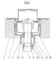
- a drain device is visible, which in an opening. 1 a ceiling or a floor 2 is at least partially introduced.
- the drain device comprises in the illustrated Embodiment, a metallic receiving means 3, a cylindrical socket 4 and one in the installed state of the upper Having end 4 of the nozzle radially outwardly projecting plate 5.
- Stub 4 and 5 plates are integrally made of metal, made of steel, for example.
- the inside of the neck 4 and of the plate 5 are coated with a fire protection compound 6, the at elevated temperatures under high volume increase can foam.
- a fire protection compound may, for example serve a so-called intumescent foam.
- the drain device further comprises a sleeve 7 extending from the Top of the plate 5 extends upward.
- the preferably off Plastic existing sleeve 7 is in principle with its lower front end on the plate 5 and is through the Bonded fire protection compound 6, which is a plastic-like Has consistency, held on the receiving means 3, so that the Whole one-piece part forms.
- Such a one-piece part is for example, from German Utility Model DE 203 02 159 U1 well known.
- the flat bars 8 are approximately horizontal at their upper end kinked, leaving them with their upper ends on top a run-up plane in the edge region around the opening 1 around can and can be attached.
- the flat bars 8 serve here on the one hand as a mortar anchor and on the other as height fixing parts.
- the Sleeve 7 has in its upper region an inner circumferential annular groove 10, in which a sealing ring 11 is received.
- the drain device further comprises a drain pot 12, the a cylindrical portion 13 which in the sleeve 7th is added so that O-ring 12 on the outside of the cylindrical portion 13 is present.
- the illustrated drain pot 12 has, for example, an odor trap. It exists however also the possibility to use other drainpots.
- illustrated embodiment is in the lower area after a downwardly extending pipe socket 14 is provided, the can be fluidically connected to a drain pipe 15.
- the fluidic connection between the lower Pipe socket 14 and the drain pipe 15 is done via a pipe section 16 made of plastic, the top of a section of larger diameter has, the outside of the lower pipe socket 14 of the drain pot 12 is postponed. Between the upper extended section of the made of plastic pipe socket 16 and the pipe socket 14th the drain pot 12, a lip seal 17 is provided. Of the lower portion of the plastic pipe piece 16 is connected via a connecting clip 18 with the drain pipe 15.
- both the drain pot 12 and the drain pipe 15 made of cast metal consist.
- Cast metal can be from the foaming Fire protection compound 6 are not compressed so that thereby a closure of the opening 1 is achieved.
- the upper edge of the drain pipe 15 and the lower edge the lower pipe socket 14 of the drain pot 12 from each other spaced, this distance through the plastic existing pipe section 16 is bridged.
- the plastic existing pipe section 16 can from the foaming Fire protection mass be compressed in case of fire, so that at this point the opening 1 of the fire protection compound. 6 can be closed.
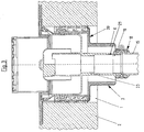
- Fig. 2 is another embodiment of an inventive Flow device can be seen in the same parts with the same Reference numerals are provided as shown in Fig. 1.
- the drain pipe 15 is made in the embodiment of FIG. 2 as well as in the Embodiment of FIG. 1 made of cast metal.
- the drain pot 20 of Embodiment of FIG. 2 in contrast to the Drain pot 12 of FIG. 1 made of plastic, so that ultimately the lower end of the drain pot 20 by the fire protection compound 6 in Fire could be squeezed.
- a plastic existing Pipe 21 provided, which is used for connection between the Drain pipe 15 and the drain pot 20 is used.
- the lower end of the out Plastic existing pipe section 21 is as in the Embodiment of FIG.
- connection clamp 18th connected to the drain pipe 15.
- the upper end of the plastic existing pipe section 21 is on a lower pipe socket 22nd pushed the drain pot 20, wherein in the lower part of the Drain pot 20 two concentric with each other Pipe sockets 22, 23 are provided.
- the seal between the made of plastic pipe section 21 and the drain pot 20th takes place via a lip seal 24, which is on the outside of the Plastic existing pipe section 21 and on the inside of the outer lower pipe socket 23 rests.
- connection between drain pot 20 and drain pipe 15th producing plastic pipe piece 21 is used in the Embodiment of FIG. 2 not primarily the improvement the sealing properties in case of fire, but puts the Connecting region between the drain pipe 15 and pipe section 21 such down that the connection clamp 18 reaches easily can be, resulting in a simplification of assembly.
- most of the connecting clip 18 is found outside of the downwardly projecting cylindrical neck 4 of the metallic receiving means 3.
- FIG. 3 is another embodiment of an inventive Flow device can be seen in the same parts with the the same reference numerals as in Fig. 1 and Fig. 2 are provided.
- a separate piece of plastic pipe has the embodiment of FIG. 3, a lower pipe socket 23 on which a downwardly extending plastic existing pipe section 21 is formed.
Landscapes
- Health & Medical Sciences (AREA)
- Life Sciences & Earth Sciences (AREA)
- Engineering & Computer Science (AREA)
- Hydrology & Water Resources (AREA)
- Public Health (AREA)
- Water Supply & Treatment (AREA)
- Sink And Installation For Waste Water (AREA)
- Building Environments (AREA)
Abstract
Description
Die vorliegende Erfindung betrifft eine Ablaufvorrichtung für die Montage in einer Boden- bzw. Deckenöffnung umfassend einen Ablauftopf, der einen Rohrstutzen für die strömungstechnische Verbindung des Ablauftopfes mit einem Ablaufrohr aufweist, sowie Brandschutzmittel, die im Falle eines Brandes die Boden- bzw. Deckenöffnung durch Aufschäumen einer Brandschutzmasse zumindest zeitweilig verschließen können.The present invention relates to a drain device for the Mounting in a floor or ceiling opening comprising a Drain pot, a pipe socket for the fluidic Connection of the drain pot with a drain pipe has, as well Fire-retardants which, in the case of fire, damage the soil or Ceiling opening by foaming a fire protection compound at least temporarily close.
Eine derartige Ablaufvorrichtung ist aus der deutschen Gebrauchsmusterschrift DE 203 02 159 U1 bekannt. Die Brandschutzmittel der darin beschriebenen Ablaufvorrichtung umfassen ein Aufnahmemittel mit einem in Einbaulage vertikal ausgerichteten zylindrischen Stutzen, an dessen oberem Ende ein sich radial nach außen erstreckender Teller angeformt ist. Auf diesem Teller steht eine sich vertikal nach oben erstreckende Muffe auf, die einen Ablauftopf haltern kann. Die Oberseite des Tellers und die Innenseite des von dem Teller nach unten ragenden zylindrischen Stutzens sind mit einer bei erhöhten Temperaturen aufschäumenden Brandschutzmasse versehen. Der in die Muffe eingesetzte Ablauftopf umfasst einen vertikal nach unten ragenden Rohrstutzen, an dem im Inneren des zylindrischen Stutzens des Aufnahmemittels vermittels einer Verbindungsschelle ein Ablaufrohr angebracht ist.Such a drainage device is from the German Utility Model DE 203 02 159 U1 known. The Fire retardant of the drainage device described therein comprise a receiving means with a vertically in the installed position aligned cylindrical neck, at its upper end a is formed radially outwardly extending plate. On this Plate is a vertically upwardly extending sleeve, the can hold a drain pot. The top of the plate and the Inside of the protruding from the plate down cylindrical Stutzens are with a foaming at elevated temperatures Fire protection compound provided. The drain pot inserted in the socket comprises a vertically projecting pipe socket on which in Inside the cylindrical neck of the receiving means mediated a connection clamp a drain pipe is attached.
Als nachteilig bei dieser aus dem Stand der Technik bekannten Ablaufvorrichtung erweist sich einerseits, dass die Verbindungsschelle im Inneren des zylindrischen Stutzens des Aufnahmemittels montiert werden muss, was unter Umständen mit erheblichem Montageaufwand verbunden ist. Zum anderen besteht nicht die Möglichkeit, bei einer Ablaufvorrichtung der aus dem Stand der Technik bekannten Art sowohl einen Ablauftopf als auch ein Ablaufrohr aus Metallguss zu verwenden, weil die im Brandfall expandierende Brandschutzmasse Metallguss nicht oder nur unwesentlich zusammendrücken kann. Dadurch kann die Decken- bzw. Bodenöffnung im Brandfall nicht mehr verschlossen werden.As disadvantageous in this known from the prior art Drain device proves, on the one hand, that the Connecting clamp inside the cylindrical neck of the Aufnahmemittels must be mounted, which may be with associated with considerable installation effort. On the other hand exists not the possibility of a drain device of the state of the art the art known both a drain pot and a Use drain pipe made of cast metal, because in case of fire expanding fire protection mass metal casting not or only insubstantially compress. This allows the ceiling or bottom opening in case of fire can not be closed.
Das der vorliegenden Erfindung zugrunde liegende Problem ist die Schaffung einer Ablaufvorrichtung der eingangs genannten Art, die einfacher zu montieren und/oder auch bei der Verwendung von Metallguss für den Ablauftopf und das Ablaufrohr brandschutztechnischen Anforderungen genügt.The problem underlying the present invention is the Creating a drain device of the type mentioned, the easier to assemble and / or even when using Metal casting for the drain pot and drain pipe fire protection requirements is sufficient.
Dies wird erfindungsgemäß durch eine Ablaufvorrichtung der eingangs
genannten Art mit den kennzeichnenden Merkmalen des Anspruchs 1
erreicht. Eine derartige Ausgestaltung der Ablaufvorrichtung bietet
zum einen den Vorteil, dass bei entsprechend lang ausgeführtem
Rohrstück aus Kunststoff der Verbindungsbereich zwischen dem
Rohrstück und dem Ablaufrohr derart nach unten verlagert werden
kann, dass eine Montage einer Verbindungsschelle einfach erfolgen
kann. Weiterhin gewährleistet die Beabstandung von Ablauftopf und
Ablaufrohr über das aus Kunststoff bestehende Rohrstück eine
ausreichende Kompressibilität dieses Zwischenraums, so dass die
expandierende Brandschutzmasse im Brandfall die Boden- bzw.
Deckenöffnung verschließen kann.This is inventively by a drain device of the beginning
mentioned type with the characterizing features of
Gemäß Anspruch 2 kann dabei vorgesehen sein, dass die
Brandschutzmittel derart in der Ablaufvorrichtung angeordnet sind,
dass im Brandfall die expandierende Brandschutzmasse in den
vertikalen Zwischenraum zwischen dem Rohrstutzen des Ablauftopfes
und dem Ablaufrohr hinein expandieren und in diesem Bereich die
Boden- bzw. Deckenöffnung verschließen kann.In accordance with
Gemäß Anspruch 3 kann vorgesehen sein, dass das Ablaufrohr aus
Metallguss besteht. According to
Gemäß Anspruch 4 kann vorgesehen sein, dass der Ablauftopfs aus
Kunststoff besteht.According to
Alternativ dazu kann gemäß Anspruch 5 vorgesehen sein, dass der
Ablauftopf aus Metallguss besteht. Selbst bei einem aus Metallguss
bestehenden Ablauftopf und einem aus Metallguss bestehenden
Ablaufrohr kann durch das zwischen den beiden angeordnete, aus
Kunststoff bestehende Rohrstück der Verschluss der Boden- bzw.
Deckenöffnung im Brandfall durch die expandierende
Brandschutzmasse gewährleistet werden.Alternatively, it may be provided according to
Gemäß Anspruch 6 kann vorgesehen sein, dass das Ablaufrohr mit
dem aus Kunststoff bestehenden Rohrstück über eine
Verbindungsschelle verbunden ist. Eine derartige Verbindungsschelle
kann beispielsweise unterhalb eines zylindrischen Abschnittes eines
Aufnahmemittels angeordnet sein.According to
Gemäß Anspruch 7 kann vorgesehen sein, dass das aus Kunststoff
bestehende Rohrstück auf den unteren Rohrstutzen aufgeschoben
oder in den unteren Rohrstutzen eingeschoben ist.According to
Gemäß Anspruch 8 kann vorgesehen sein, dass das aus Kunststoff
bestehende Rohrstück zumindest in dem Zwischenraum zwischen
unterem Ende des Ablauftopfes und oberem Ende des Ablaufrohres
zumindest teilweise von einem metallischen Aufnahmemittel umgeben
ist, an dessen Innenseite Brandschutzmasse angeordnet ist. Durch
das Umgeben der Brandschutzmasse mit einem metallischen
Aufnahmemittel wird gewährleistet, dass die Brandschutzmasse nach
innen expandiert und damit in diesem Bereich die Boden- bzw.
Deckenöffnung verschließen kann. According to
Weitere Merkmale und Vorteile der vorliegenden Erfindung werden deutlich anhand der nachfolgenden Beschreibung bevorzugter Ausführungsbeispiele unter Bezugnahme auf die beiliegenden Abbildungen. Darin zeigen
- Fig. 1
- eine Schnittansicht einer ersten Ausführungsform einer erfindungsgemäßen Ablaufvorrichtung;
- Fig. 2
- eine Schnittansicht einer zweiten Ausführungsform einer erfindungsgemäßen Ablaufvorrichtung;
- Fig. 3
- eine Schnittansicht einer dritten Ausführungsform einer erfindungsgemäßen Ablaufvorrichtung.
- Fig. 1
- a sectional view of a first embodiment of a drain device according to the invention;
- Fig. 2
- a sectional view of a second embodiment of a drain device according to the invention;
- Fig. 3
- a sectional view of a third embodiment of a drain device according to the invention.
Aus Fig. 1 ist eine Ablaufvorrichtung ersichtlich, die in eine Öffnung 1
einer Decke oder eines Bodens 2 zumindest teilweise eingebracht ist.
Die Ablaufvorrichtung umfasst in dem abgebildeten
Ausführungsbeispiel ein metallisches Aufnahmemittel 3, das einen
zylindrischen Stutzen 4 und einen im Einbauzustand von dem oberen
Ende des Stutzens 4 radial nach außen ragenden Teller 5 aufweist.
Stutzen 4 und Teller 5 sind dabei einstückig aus Metall,
beispielsweise aus Stahl gefertigt. Die Innenseite des Stutzens 4 und
des Tellers 5 sind mit einer Brandschutzmasse 6 beschichtet, die bei
erhöhten Temperaturen unter starker Volumenvergrößerung
aufschäumen kann. Als Brandschutzmasse kann dabei beispielsweise
ein sogenannter Intumeszenz-Schaumstoff dienen.From Fig. 1, a drain device is visible, which in an opening. 1
a ceiling or a
Die Ablaufvorrichtung umfasst weiterhin eine Muffe 7, die sich von der
Oberseite des Tellers 5 nach oben erstreckt. Die vorzugsweise aus
Kunststoff bestehende Muffe 7 steht im Prinzip mit ihrem unteren
stirnseitigen Ende auf dem Teller 5 auf und wird durch die
abgebundene Brandschutzmasse 6, die eine kunststoffartige
Konsistenz aufweist, an dem Aufnahmemittel 3 gehalten, so dass das
Ganze ein einstückiges Teil bildet. Ein derartiges einstückiges Teil ist
beispielsweise aus dem deutschen Gebrauchsmuster DE 203 02 159
U1 hinlänglich bekannt.The drain device further comprises a
An dem Teller 5 sind Befestigungseinrichtungen in Form von
Flacheisen 8 angebracht, die sich von dem Teller 5 aus in einem
stumpfen Winkel radial schräg nach außen und oben erstrecken. Es
sind über den Umfang verteilt mehrere dieser Flacheisen 8
vorhanden, die an dem Teller 5 beispielsweise angeschweißt werden
können. Die Flacheisen 8 sind an ihrem oberen Ende etwa horizontal
abgeknickt, so dass sie mit ihren oberen Enden auf der Oberseite
einer Auflaufebene im Randbereich um die Öffnung 1 herum aufliegen
können und befestigt werden können. Die Flacheisen 8 dienen hierbei
zum einen als Mörtelanker und zum anderen als Höhenfixierungsteile.On the
Nach dem Auflegen der Flacheisen 8 im Randbereich der Öffnung 1
kann beispielweise durch eine Vergussmasse 9 der verbleibende
Ringspalt zwischen Muffe 7 und Öffnung 1 verschlossen werden. Die
Muffe 7 weist in ihrem oberen Bereich eine innen umlaufende Ringnut
10 auf, in der ein Dichtungsring 11 aufgenommen ist.After placing the
Die Ablaufvorrichtung umfasst weiterhin einen Ablauftopf 12, der
einen zylindrischen Abschnitt 13 aufweist, der in der Muffe 7
aufgenommen ist, so dass O-Ring 12 an der Außenseite des
zylindrischen Abschnittes 13 anliegt. Der abgebildete Ablauftopf 12
weist beispielsweise einen Geruchsverschluss auf. Es besteht aber
auch die Möglichkeit, andere Ablauftöpfe zu verwenden. Bei dem
abgebildeten Ausführungsbeispiel ist im unteren Bereich ein sich nach
unten erstreckender Rohrstutzen 14 vorgesehen, der
strömungstechnisch mit einem Ablaufrohr 15 verbunden werden kann. The drain device further comprises a
Die strömungstechnische Verbindung zwischen dem unteren
Rohrstutzen 14 und dem Ablaufrohr 15 geschieht über ein Rohrstück
16 aus Kunststoff, das oben einen Abschnitt größeren Durchmessers
aufweist, der außen auf den unteren Rohrstutzen 14 des Ablauftopfes
12 aufgeschoben ist. Zwischen dem oberen erweiterten Abschnitt des
aus Kunststoff bestehenden Rohrstutzen 16 und dem Rohrstutzen 14
des Ablauftopfes 12 ist eine Lippendichtung 17 vorgesehen. Der
untere Abschnitt des aus Kunststoff bestehenden Rohrstückes 16 ist
über eine Verbindungsschelle 18 mit dem Ablaufrohr 15 verbunden.The fluidic connection between the
Es besteht die Möglichkeit, dass in das untere Ende des aus
Kunststoff bestehenden Rohrstückes 16 ein Metallstützring 19
eingebracht wird, der ein Verschrauben des aus Kunststoff
bestehenden Rohrstückes 16 mit dem Ablaufrohr 15 über die
Verbindungsschelle 18 erleichtert.There is a possibility that in the lower end of the
Plastic existing pipe section 16 a metal support ring 19th
is introduced, the screwing of the plastic
existing
Bei dem in Fig. 1 abgebildeten Ausführungsbeispiel können sowohl
der Ablauftopf 12 als auch das Ablaufrohr 15 aus Metallguss
bestehen. Metallguss kann von der aufschäumenden
Brandschutzmasse 6 nicht derart zusammengedrückt werden, dass
dadurch ein Verschluss der Öffnung 1 erzielt wird. Aus diesem
Grunde sind die Oberkante des Ablaufrohres 15 und die Unterkante
des unteren Rohrstutzens 14 des Ablauftopfes 12 voneinander
beabstandet, wobei dieser Abstand durch das aus Kunststoff
bestehende Rohrstück 16 überbrückt wird. Das aus Kunststoff
bestehende Rohrstück 16 kann von der aufschäumenden
Brandschutzmasse im Brandfall zusammengedrückt werden, so dass
an dieser Stelle die Öffnung 1 von der Brandschutzmasse 6
verschlossen werden kann.In the embodiment shown in Fig. 1, both
the
Aus Fig. 2 ist eine weitere Ausführungsform einer erfindungsgemäßen
Ablaufvorrichtung ersichtlich, bei der gleiche Teile mit den gleichen
Bezugszeichen wie in Fig. 1 versehen sind. Das Ablaufrohr 15 besteht
bei der Ausführungsform gemäß Fig. 2 ebenso wie bei der
Ausführungsform gemäß Fig. 1 aus Metallguss. Der Ablauftopf 20 der
Ausführungsform gemäß Fig. 2 besteht jedoch im Unterschied zu dem
Ablauftopf 12 gemäß Fig. 1 aus Kunststoff, so dass letztlich das
untere Ende des Ablauftopfes 20 durch die Brandschutzmasse 6 im
Brandfall zusammengedrückt werden könnte. Trotzdem ist auch bei
der Ausführungsform gemäß Fig. 2 ein aus Kunststoff bestehendes
Rohrstück 21 vorgesehen, das zur Verbindung zwischen dem
Ablaufrohr 15 und dem Ablauftopf 20 dient. Das untere Ende des aus
Kunststoff bestehenden Rohrstückes 21 ist wie bei der
Ausführungsform gemäß Fig. 1 mittels einer Verbindungsschelle 18
mit dem Ablaufrohr 15 verbunden. Das obere Ende des aus Kunststoff
bestehenden Rohrstückes 21 ist auf einen unteren Rohrstutzen 22
des Ablauftopfes 20 aufgeschoben, wobei im unteren Bereich des
Ablauftopfes 20 zwei konzentrisch zueinander angeordnete
Rohrstutzen 22, 23 vorgesehen sind. Die Abdichtung zwischen dem
aus Kunststoff bestehenden Rohrstück 21 und dem Ablauftopf 20
erfolgt über eine Lippendichtung 24, die an der Außenseite des aus
Kunststoff bestehenden Rohrstückes 21 und an der Innenseite des
äußeren unteren Rohrstutzens 23 anliegt.From Fig. 2 is another embodiment of an inventive
Flow device can be seen in the same parts with the same
Reference numerals are provided as shown in Fig. 1. The
Es besteht alternativ die Möglichkeit, dass ein aus Kunststoff
bestehendes Rohrstück entsprechend der Ausführungsform gemäß
Fig. 1 gewählt wird, das von außen auf den äußeren unteren
Rohrstutzen 23 aufgebracht werden kann.There is alternatively the possibility of having a plastic
existing pipe section according to the embodiment according to
Fig. 1 is selected, the outside of the outer
Das die Verbindung zwischen Ablauftopf 20 und Ablaufrohr 15
herstellende aus Kunststoff bestehende Rohrstück 21 dient bei der
Ausführungsform gemäß Fig. 2 nicht in erster Linie der Verbesserung
der Abdichteigenschaften im Brandfall, sondern versetzt den
Verbindungsbereich zwischen Ablaufrohr 15 und Rohrstück 21 derart
nach unten, dass die Verbindungsschelle 18 problemlos erreicht
werden kann, wodurch sich eine Montagevereinfachung ergibt.
Insbesondere findet sich der größte Teil der Verbindungsschelle 18
außerhalb des nach unten ragenden zylindrischen Stutzens 4 des
metallischen Aufnahmemittels 3.This is the connection between
Es besteht erfindungsgemäß die Möglichkeit, unterschiedlichste
Ablauftöpfe an ihrer Unterseite mit einem aus Kunststoff bestehenden
Rohrstück zur Verbindung mit einem insbesondere aus Metallguss
bestehenden Ablaufrohr 15 zu versehen.There is according to the invention the possibility of very different
Drain pots on their underside with a plastic one
Pipe piece for connection to a particular cast metal
to provide existing
Aus Fig. 3 ist eine weitere Ausführungsform einer erfindungsgemäßen
Ablaufvorrichtung ersichtlich, bei der ebenfalls gleiche Teile mit den
gleichen Bezugszeichen wie in Fig. 1 und Fig. 2 versehen sind.
Anstelle eines separaten aus Kunststoff bestehenden Rohrstücks
weist die Ausführungsform gemäß Fig. 3 einen unteren Rohrstutzen
23 auf, an dem ein sich nach unten erstreckendes aus Kunststoff
bestehendes Rohrstück 21 angeformt ist. From Fig. 3 is another embodiment of an inventive
Flow device can be seen in the same parts with the
the same reference numerals as in Fig. 1 and Fig. 2 are provided.
Instead of a separate piece of plastic pipe
has the embodiment of FIG. 3, a
- 11
- Öffnungopening
- 22
- Deckelcover
- 33
- metallisches Aufnahmemittelmetallic receiving means
- 44
- zylindrischer Stutzencylindrical neck
- 55
- radialer Tellerradial plate
- 66
- BrandschutzmasseBrandschutzmasse
- 77
- Muffesleeve
- 88th
- Flacheisenflat iron
- 99
- Vergussmassepotting compound
- 1010
- Ringnutring groove
- 1111
- Dichtungsringsealing ring
- 1212
- Ablauftopfdrain pot
- 1313
- zylindrischer Abschnittcylindrical section
- 1414
- unterer Rohrstutzenlower pipe socket
- 1515
- Ablaufrohrdrain pipe
- 1616
- Rohrstück aus KunststoffPipe piece made of plastic
- 1717
- Lippendichtunglip seal
- 1818
- Verbindungsschelleconnection clamp
- 1919
- MetallstützringMetal support ring
- 2020
- Ablauftopfdrain pot
- 2121
- Rohrstück aus KunststoffPipe piece made of plastic
- 2222
- unterer Rohrstutzenlower pipe socket
- 2323
- unterer Rohrstutzenlower pipe socket
- 2424
- Lippendichtunglip seal
Claims (8)
Applications Claiming Priority (2)
| Application Number | Priority Date | Filing Date | Title |
|---|---|---|---|
| DE2003149798 DE10349798A1 (en) | 2003-10-24 | 2003-10-24 | Drainage device for mounting in a floor or ceiling opening |
| DE10349798 | 2003-10-24 |
Publications (2)
| Publication Number | Publication Date |
|---|---|
| EP1528307A2 true EP1528307A2 (en) | 2005-05-04 |
| EP1528307A3 EP1528307A3 (en) | 2008-10-29 |
Family
ID=34399552
Family Applications (1)
| Application Number | Title | Priority Date | Filing Date |
|---|---|---|---|
| EP04018895A Withdrawn EP1528307A3 (en) | 2003-10-24 | 2004-08-10 | Floor drain with fireproofing material |
Country Status (2)
| Country | Link |
|---|---|
| EP (1) | EP1528307A3 (en) |
| DE (1) | DE10349798A1 (en) |
Cited By (3)
| Publication number | Priority date | Publication date | Assignee | Title |
|---|---|---|---|---|
| EP2402520A1 (en) | 2010-07-01 | 2012-01-04 | TECE GmbH | Fire protection for floor drain |
| EP2778306A1 (en) * | 2013-03-11 | 2014-09-17 | ACO Severin Ahlmann GmbH & Co. KG | Floor drain mounting device |
| EP2899326A1 (en) * | 2014-01-28 | 2015-07-29 | WEDI GmbH | Water outlet with at least one prefabricated fire protection element |
Citations (4)
| Publication number | Priority date | Publication date | Assignee | Title |
|---|---|---|---|---|
| DE2713689A1 (en) * | 1976-04-14 | 1977-10-20 | Pont A Mousson | Fire arrester for fusible pipe connected through wall - has annular connecting piece with chemical foam mix expanded by heat to seal opening |
| US4136707A (en) * | 1976-08-31 | 1979-01-30 | Pont-A-Mousson S.A. | Fire-resisting device for piping extending through a wall |
| AU713645B2 (en) * | 1996-07-08 | 1999-12-09 | Douglas Leslie Matthews | Adjustable fire rated floor penetration |
| DE20016820U1 (en) * | 2000-09-29 | 2002-02-14 | Franz Viegener II GmbH & Co. KG, 57439 Attendorn | Water drain pipe with a fire protection ring |
-
2003
- 2003-10-24 DE DE2003149798 patent/DE10349798A1/en not_active Ceased
-
2004
- 2004-08-10 EP EP04018895A patent/EP1528307A3/en not_active Withdrawn
Patent Citations (4)
| Publication number | Priority date | Publication date | Assignee | Title |
|---|---|---|---|---|
| DE2713689A1 (en) * | 1976-04-14 | 1977-10-20 | Pont A Mousson | Fire arrester for fusible pipe connected through wall - has annular connecting piece with chemical foam mix expanded by heat to seal opening |
| US4136707A (en) * | 1976-08-31 | 1979-01-30 | Pont-A-Mousson S.A. | Fire-resisting device for piping extending through a wall |
| AU713645B2 (en) * | 1996-07-08 | 1999-12-09 | Douglas Leslie Matthews | Adjustable fire rated floor penetration |
| DE20016820U1 (en) * | 2000-09-29 | 2002-02-14 | Franz Viegener II GmbH & Co. KG, 57439 Attendorn | Water drain pipe with a fire protection ring |
Cited By (5)
| Publication number | Priority date | Publication date | Assignee | Title |
|---|---|---|---|---|
| EP2402520A1 (en) | 2010-07-01 | 2012-01-04 | TECE GmbH | Fire protection for floor drain |
| DE102010030836A1 (en) | 2010-07-01 | 2012-01-05 | Tece Gmbh | Fire protection for floor drain |
| DE102010030836B4 (en) * | 2010-07-01 | 2014-12-31 | Tece Gmbh | Fire protection for floor drain |
| EP2778306A1 (en) * | 2013-03-11 | 2014-09-17 | ACO Severin Ahlmann GmbH & Co. KG | Floor drain mounting device |
| EP2899326A1 (en) * | 2014-01-28 | 2015-07-29 | WEDI GmbH | Water outlet with at least one prefabricated fire protection element |
Also Published As
| Publication number | Publication date |
|---|---|
| DE10349798A1 (en) | 2005-05-25 |
| EP1528307A3 (en) | 2008-10-29 |
Similar Documents
| Publication | Publication Date | Title |
|---|---|---|
| EP3384568B1 (en) | Frame profile for an electrical cabinet frame work and corresponding frame work | |
| DE202013103517U1 (en) | Fastening arrangement for a faucet | |
| DE102011006201A1 (en) | Holder for a fire sleeve | |
| EP1329562B1 (en) | Floor drain | |
| EP1577453B1 (en) | Floor drain | |
| EP1674628B1 (en) | Drainage device. | |
| EP1528307A2 (en) | Floor drain with fireproofing material | |
| EP1453574B1 (en) | Fire-barrier outlet | |
| DE102004007454A1 (en) | Runoff pot fire protection for buildings comprises protective mass dropped into pipe at excess temperature to protect mass from waste water and consequent loss of efficacy. | |
| WO2015117763A1 (en) | Clamp | |
| DE102013109367A1 (en) | floor drain | |
| DE10201287C5 (en) | floor drain | |
| EP2402520B1 (en) | Fire protection for floor drain | |
| DE202007012669U1 (en) | Recessed box for electrical installations | |
| DE10360310A1 (en) | draining device | |
| AT501247A1 (en) | FLOOR DRAIN | |
| EP2447436A1 (en) | Roof gulley | |
| CH438166A (en) | Toilet cistern built into the wall | |
| EP2192252A1 (en) | Plug | |
| DE202005012876U1 (en) | Fireproof collar for pipes passing through ceilings or walls has protrusions on outer face of swellable material of sleeve creating friction coefficient for fireproof collar to be fastened on pipes with diameter difference | |
| EP2853643B1 (en) | Connecting body system for a concealed mounted sanitary fixture | |
| EP1785540B1 (en) | Device for draining surface water with fire protection | |
| DE102011013349A1 (en) | Discharge device e.g. floor drain for waste water used in e.g. bathroom, has sealing unit that is in contact with the drain port of trap | |
| DE102008034435A1 (en) | Flame protection device for a pipe coupling and pipe coupling | |
| DE102004020251A1 (en) | Drain, for floors and roofs, has a unit inserted into the drain hole for connection to the drainpipe with a horizontal closure plate with slits to cover the gap between the unit and the wall of the opening |
Legal Events
| Date | Code | Title | Description |
|---|---|---|---|
| PUAI | Public reference made under article 153(3) epc to a published international application that has entered the european phase |
Free format text: ORIGINAL CODE: 0009012 |
|
| AK | Designated contracting states |
Kind code of ref document: A2 Designated state(s): AT BE BG CH CY CZ DE DK EE ES FI FR GB GR HU IE IT LI LU MC NL PL PT RO SE SI SK TR |
|
| AX | Request for extension of the european patent |
Extension state: AL HR LT LV MK |
|
| PUAL | Search report despatched |
Free format text: ORIGINAL CODE: 0009013 |
|
| AK | Designated contracting states |
Kind code of ref document: A3 Designated state(s): AT BE BG CH CY CZ DE DK EE ES FI FR GB GR HU IE IT LI LU MC NL PL PT RO SE SI SK TR |
|
| AX | Request for extension of the european patent |
Extension state: AL HR LT LV MK |
|
| AKX | Designation fees paid | ||
| STAA | Information on the status of an ep patent application or granted ep patent |
Free format text: STATUS: THE APPLICATION IS DEEMED TO BE WITHDRAWN |
|
| 18D | Application deemed to be withdrawn |
Effective date: 20090430 |
|
| REG | Reference to a national code |
Ref country code: DE Ref legal event code: 8566 |