EP4471986A1 - Antennenelement und antennenvorrichtung - ep - Google Patents
Antennenelement und antennenvorrichtung - ep Download PDFInfo
- Publication number
- EP4471986A1 EP4471986A1 EP24177640.0A EP24177640A EP4471986A1 EP 4471986 A1 EP4471986 A1 EP 4471986A1 EP 24177640 A EP24177640 A EP 24177640A EP 4471986 A1 EP4471986 A1 EP 4471986A1
- Authority
- EP
- European Patent Office
- Prior art keywords
- antenna element
- upper conductor
- orientation
- legs
- pair
- Prior art date
- Legal status (The legal status is an assumption and is not a legal conclusion. Google has not performed a legal analysis and makes no representation as to the accuracy of the status listed.)
- Granted
Links
Images


Classifications
-
- H—ELECTRICITY
- H01—ELECTRIC ELEMENTS
- H01Q—ANTENNAS, i.e. RADIO AERIALS
- H01Q9/00—Electrically-short antennas having dimensions not more than twice the operating wavelength and consisting of conductive active radiating elements
- H01Q9/04—Resonant antennas
- H01Q9/0407—Substantially flat resonant element parallel to ground plane, e.g. patch antenna
- H01Q9/0428—Substantially flat resonant element parallel to ground plane, e.g. patch antenna radiating a circular polarised wave
- H01Q9/0435—Substantially flat resonant element parallel to ground plane, e.g. patch antenna radiating a circular polarised wave using two feed points
-
- H—ELECTRICITY
- H01—ELECTRIC ELEMENTS
- H01Q—ANTENNAS, i.e. RADIO AERIALS
- H01Q1/00—Details of, or arrangements associated with, antennas
- H01Q1/36—Structural form of radiating elements, e.g. cone, spiral, umbrella; Particular materials used therewith
-
- H—ELECTRICITY
- H01—ELECTRIC ELEMENTS
- H01Q—ANTENNAS, i.e. RADIO AERIALS
- H01Q1/00—Details of, or arrangements associated with, antennas
- H01Q1/12—Supports; Mounting means
-
- H—ELECTRICITY
- H01—ELECTRIC ELEMENTS
- H01Q—ANTENNAS, i.e. RADIO AERIALS
- H01Q1/00—Details of, or arrangements associated with, antennas
- H01Q1/12—Supports; Mounting means
- H01Q1/22—Supports; Mounting means by structural association with other equipment or articles
-
- H—ELECTRICITY
- H01—ELECTRIC ELEMENTS
- H01Q—ANTENNAS, i.e. RADIO AERIALS
- H01Q9/00—Electrically-short antennas having dimensions not more than twice the operating wavelength and consisting of conductive active radiating elements
- H01Q9/04—Resonant antennas
- H01Q9/0407—Substantially flat resonant element parallel to ground plane, e.g. patch antenna
- H01Q9/0421—Substantially flat resonant element parallel to ground plane, e.g. patch antenna with a shorting wall or a shorting pin at one end of the element
Definitions
- This invention relates to an antenna element and an antenna device using the antenna element.
- an antenna device 90 of JPA 2022-150365 (Patent Document 1) comprises a printed circuit board 94, a supporting portion 96 and an antenna element 98.
- the printed circuit board 94 has a ground conductor 92.
- the antenna element 98 is formed of conductor and is fixed on the printed circuit board 94 via the supporting portion 96.
- the ground conductor 92 and the antenna element 98 are physically away from each other.
- the antenna element 98 has rotational symmetry in order to transmit/receive circularly polarized radio wave.
- the antenna element 98 is formed by bending a metal plate 99 shown in Fig. 12 .
- a developed plan of the antenna element 98 has a shape with four-fold rotational symmetry.
- a developed plan of an antenna element In order to reduce material cost, it is desirable for a developed plan of an antenna element, especially its outer periphery, to have a shape with line symmetry.
- the modified antenna element lacks rotational symmetry and thereby axial ratio characteristics of an antenna device using the modified antenna element is degraded.
- the inventor of the present invention has found that a provision of a recessed portion in the vicinity of a leg can compensate the lack of rotational symmetry of the modified antenna element and thereby the axial ratio characteristics of the antenna device can be improved. Accordingly, a provision of a recessed portion at a predetermined location of an antenna element enables the antenna element to be designed in a manner that is suitable for transmitting/receiving circularly polarized radio wave and that reduces material cost.
- the provision of the recessed portion in the antenna element which is formed from a metal plate, improves axial ratio characteristics of the antenna device.
- This technique is also applicable to an antenna element other than the antenna element formed from the metal plate. If an antenna element itself is not required to have rotational symmetry, the antenna element can have somewhat increased design flexibility.
- a provision of a recessed portion at a predetermined location of an antenna element enables the antenna element to be designed in a manner that is suitable for transmitting/receiving circularly polarized radio wave and that has increased design flexibility.
- the present invention is based on this finding. Specifically, the present invention provides an antenna element as follows.
- One aspect (first aspect) of the present invention provides an antenna element configured to be fixed on a printed circuit board with a ground conductor.
- the antenna element and the printed circuit board form an antenna device when the antenna element is fixed on the printed circuit board.
- the antenna element comprises an upper conductor and at least one pair of legs.
- the upper conductor When the upper conductor is viewed along an up-down direction, the upper conductor has an outer periphery whose shape is line-symmetrical with respect to a line passing through a center of the upper conductor.
- one of the legs of the pair protrudes in a first orientation while a remaining one of the legs of the pair protrudes in a second orientation.
- the first orientation from the center of the upper conductor is opposite to the second orientation from the center of the upper conductor.
- Each of the legs of the pair extends downward in the up-down direction.
- the upper conductor is provided with at least one pair of recessed portions.
- the recessed portions of the pair correspond to the legs of the pair in a one-to-one relationship.
- one of the recessed portions of the pair is recessed in the second orientation while a remaining one of the recessed portions of the pair is recessed in the first orientation.
- Each of the recessed portions is juxtaposed with the corresponding leg in a direction intersecting with a first direction which is defined by the first orientation and the second orientation.
- Another aspect (second aspect) of the present invention provides an antenna device comprising the antenna element of the first aspect and the printed circuit board.
- the printed circuit board has the ground conductor.
- the antenna element is fixed on the printed circuit board.
- the antenna element is configured as follows: when the upper conductor is viewed along the up-down direction, the one of the legs of the pair protrudes in the first orientation while the remaining one of the legs of the pair protrudes in the second orientation; the first orientation from the center of the upper conductor is opposite to the second orientation from the center of the upper conductor; each of the legs of the pair extends downward in the up-down direction; each of the recessed portions is juxtaposed with the corresponding leg in the direction intersecting with the first direction which is defined by the first orientation and the second orientation; and, when the upper conductor is viewed along the up-down direction, the one of the recessed portions of the pair is recessed in the second orientation while the remaining one of the recessed portions of the pair is recessed in the first orientation.
- the present invention can provide the antenna element suitable for transmitting/receiving circularly polarized radio wave, and can also provide the antenna device with improved axial ratio characteristics.
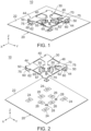
- an antenna device 10 comprises a printed circuit board 20 and an antenna element 30.
- the printed circuit board 20 has a ground conductor 22.
- the printed circuit board 20 has the ground conductor 22, solder pads 24, 26 and feeding pads 28.
- each of the ground conductor 22, the solder pads 24, 26 and the feeding pads 28 is formed on a dielectric substrate.
- the ground conductor 22, the solder pads 24, 26 and the feeding pads 28 are separated from each other.
- Each of the solder pads 24, 26 of the present embodiment is left electrically floating. Specifically, each of the solder pads 24, 26 of the present embodiment is not electrically connected with any other part of the printed circuit board 20.
- each of the feeding pads 28 is electrically connected to an outside part of the antenna device 10 by unshown means.
- the printed circuit board 20 is not limited thereto. Specifically, there is no restriction on the size and shape of the printed circuit board 20, provided that the printed circuit board 20 has the ground conductor 22.
- the printed circuit board 20 may have an additional ground conductor or another conductor.
- the antenna element 30 is fixed on the printed circuit board 20.
- An explanation will be made later about a specific method of fixing the antenna element 30 on the printed circuit board 20.
- the antenna element 30 comprises an upper conductor 40, legs 50, lower conductors 60, feeding portions 70 and stubs 75.
- the antenna element 30 of the present embodiment is formed from a single metal plate.
- the antenna element 30 of the present embodiment is integrally formed by punching out a blank from the metal plate serving as base material, followed by bending the blank.
- the present invention is not limited thereto.
- the antenna element 30 may be formed by Laser Direct Structuring (LDS) Technology.
- LDS Laser Direct Structuring
- the upper conductor 40 of the present embodiment extends in a predetermined plane perpendicular to an up-down direction.
- the upper conductor 40 When the upper conductor 40 is viewed along the up-down direction, the upper conductor 40 has an outer periphery whose shape is line-symmetrical with respect to a line passing through a center of the upper conductor 40.
- the up-down direction is a Z-direction. Specifically, it is assumed that upward is a positive Z-direction while downward is a negative Z-direction.
- the predetermined plane is a horizontal plane, or an XY-plane. Referring to Figs. 1 and 4 , the predetermined plane of the present embodiment is a plane parallel to an upper surface of the printed circuit board 20.
- the upper conductor 40 of the present embodiment extends parallel to the upper surface of the printed circuit board 20.
- the upper conductor 40 is not limited thereto.
- the upper conductor 40 should extend, at least in part, in a direction parallel to the upper surface of the printed circuit board 20.
- a specific imaginary rectangle 42 is assumed as follows: the specific imaginary rectangle 42 is positioned on the predetermined plane; the specific imaginary rectangle 42 has four sides; the specific imaginary rectangle 42 encloses the upper conductor 40; and the specific imaginary rectangle 42 is of minimum area.
- the specific imaginary rectangle 42 of the present embodiment is a square. In other words, the specific imaginary rectangle 42 has four-fold rotational symmetry.
- the antenna element 30 with the upper conductor 40, which is enclosed by the specific imaginary rectangle 42 fulfilling the above conditions, is essentially suitable for communication using circularly polarized radio wave.
- the specific imaginary rectangle 42 is not limited to the square.
- the specific imaginary rectangle 42 may be an oblong rectangle, provided that a lack of rotational symmetry of the antenna element 30 is compensated.
- the number of the feeding portions 70 of the present embodiment is two.
- the feeding portions 70 are connected to the feeding pads 28, respectively.
- each of the feeding portions 70 is formed by bending a part of the upper conductor 40.
- the upper conductor 40 is formed also with slots 46 as a result of the formation of the feeding portions 70.
- an imaginary line connecting the center of the upper conductor 40 with one of the feeding portions 70 and an imaginary line connecting the center of the upper conductor 40 with a remaining one of the feeding portions 70 are at 90 degrees to each other. Accordingly, the antenna element 30 can achieve communication, which uses circularly polarized radio wave, by being fed at two points, namely the feeding portions 70.
- the antenna element 300 of the present embodiment comprises four of the legs 50.
- the specific imaginary rectangle 42 includes two sides each of which is perpendicular to a Y-direction, and each of two of the legs 50 extends from one of the two sides of the specific imaginary rectangle 42 while each of remaining two of the legs 50 extends from a remining one of the two sides of the specific imaginary rectangle 42.
- the antenna element 30 of the present embodiment comprises two pairs each consisting of the legs 50.
- one of the legs 50 is positioned on one of the two sides of the specific imaginary rectangle 42, which is positioned beyond the center of the upper conductor 40 in a first orientation, while a remining one of the legs 50 is positioned on a remaining one of the two sides of the specific imaginary rectangle 42, which is positioned beyond the center of the upper conductor 40 in a second orientation.
- the first orientation is a positive Y-direction, or rightward in Fig. 4
- the second orientation is a negative Y-direction, or leftward in Fig. 4 .
- each of the legs 50 of each of the pairs protrudes in the first orientation while a remaining one of the legs 50 of each of the pairs protrudes in the second orientation.
- the first orientation from the center of the upper conductor 40 is opposite to the second orientation from the center of the upper conductor 40.
- Each of the legs 50 of each of the pairs extends downward in the up-down direction.
- each of two of the legs 50 of the present embodiment protrudes from the upper conductor 40 in the positive Y-direction and then extends in the negative Z-direction
- each of remining two of the legs 50 of the present embodiment protrudes from the upper conductor 40 in the negative Y-direction and then extends in the negative Z-direction.
- the antenna element 30 of the present embodiment is configured as follows: when the upper conductor 40 is viewed along the up-down direction, each of the two legs 50 extends from a positive Y-side of the specific imaginary rectangle 42 while each of the remining two legs 50 extends from a negative Y-side of the specific imaginary rectangle 42.
- the antenna element 30 may be configured as follows: when the upper conductor 40 is viewed along the up-down direction, one of the legs 50 of a pair extends from the positive Y-side of the specific imaginary rectangle 42 while a remining one of the legs 50 of the pair extends from the negative Y-side of the specific imaginary rectangle 42.
- the antenna element 30 should comprise at least one pair of the legs 50.
- the upper conductor 40 is provided with four recessed portions 44.
- the recessed portions 44 correspond to the legs 50 in a one-to-one relationship. Specifically, in the present embodiment, the number of the recessed portions 44 is equal to the number of the legs 50. As shown in Fig. 4 , the leg 50 and the corresponding recessed portion 44 are positioned on the same side among the four sides of the specific imaginary rectangle 42.
- two sides of the specific imaginary rectangle 42 are perpendicular to the Y-direction.
- One of the two sides is provided with two of the recessed portions 44 while a remining one of the two sides is provided with remaining two of the recessed portions 44.
- the upper conductor 40 of the present embodiment is provided with two pairs each consisting of the recessed portions 44.
- An object of the provision of the recessed portions 44 is to compensate the lack of the rotational symmetry of the antenna element 30 which is caused by a linearly symmetrical arrangement of the legs 50.
- each of the recessed portions 44 is juxtaposed with the corresponding leg 50 in a direction intersecting with a first direction which is defined by the first orientation and the second orientation, or with the Y-direction.
- the antenna element 30 of the present embodiment is configured so that each of the recessed portions 44 is arranged adjacent to the corresponding leg 50 in a second direction perpendicular to the first direction defined by the first orientation and the second orientation, or to the Y-direction.
- the recessed portions 44 are arranged similar to the legs 50. Specifically, each of two of the recessed portions 44 is provided at the positive Y-side of the specific imaginary rectangle 42 while each of remining two of the recessed portions 44 is provided at the negative Y-side of the specific imaginary rectangle 42.
- the present invention is not limited thereto.
- the antenna element 30 should be configured as follows; when the upper conductor 40 is viewed along the up-down direction, one of the recessed portions 44 of a pair is provided at the positive Y-side of the specific imaginary rectangle 42 while a remining one of the recessed portions 44 of the pair is provided at the negative Y-side of the specific imaginary rectangle 42.
- the upper conductor 40 should be provided with at least one pair of the recessed portions 44 according to the legs 50.
- each of the two recessed portions 44 which is provided at the positive Y-side of the specific imaginary rectangle 42, is recessed in the negative Y-direction
- each of the remining two recessed portions 44 which is provided at the negative Y-side of the specific imaginary rectangle 42, is recessed in the positive Y-direction.
- the former recessed portion 44 is recessed in the second orientation while the latter recessed portion 44 is recessed in the first orientation.
- the former recessed portion 44 and the latter recessed portion 44 are recessed in orientations opposite to each other.
- each of the recessed portions 44 has a wide shape as follows: each of the recessed portions 44 has a size in the first direction and another size in the second direction perpendicular to the first direction, and the size of each of the recessed portions 44 in the second direction is greater than the size of each of the recessed portions 44 in the first direction. In other words, the size of each of the recessed portions 44 in an X-direction is greater than the size of each of the recessed portions 44 in the Y-direction.
- the Y-direction is a direction in which each of the recessed portions 44 is recessed
- the X-direction is a direction perpendicular to the direction in which each of the recessed portions 44 is recessed
- the size of each of the recessed portions 44 in the latter direction is greater than the size of each of the recessed portions 44 in the former direction.
- the antenna element 30 of the present embodiment is configured so that a width of each of the recessed portions 44 is greater than a width of the corresponding leg 50. It is noted that the width of the recessed portion 44 is its size in the X-direction while the width of the leg 50 is its size in the X-direction.
- the shape of the recessed portion 44 is not limited thereto.
- the recessed portion 44 may have, for example, a narrow shape so that the size of the recessed portion 44 in the X-direction is smaller than the size of the recessed portion 44 in the Y-direction.
- a shape of a periphery of the recessed portion 44 is not limited to a rectangle, but also may be a shape including a curved portion, such as a semi-circular shape or a semi-elliptical shape.
- the lower conductors 60 of the present embodiment extend from the legs 50, respectively. Specifically, each of the lower conductors 60 extends in a direction parallel to the upper surface of the printed circuit board 20, and each of the lower conductors 60 is positioned away from the upper conductor 40 in the up-down direction. In other words, each of the lower conductors 60 of the present embodiment extends parallel to the upper conductor 40. Accordingly, the upper conductor 40 and each of the lower conductors 60 form a capacitor.
- the shapes and arrangement of the lower conductors 60 are not limited thereto, provided that the lower conductor 60 and the upper conductor 40 form a capacitor. However, in order to suppress a variation of its capacitance due to a dimensional tolerance variation of the antenna element 30, each of the lower conductors 60 should extend, at least in part, in the direction parallel to the upper surface of the printed circuit board 20.
- the antenna element 30 of the present embodiment comprises fixed portions 62 which extend downward from the lower conductors 60, respectively.
- the fixed portions 62 are soldered and fixed to the solder pads 24, respectively, of the printed circuit board 20. Accordingly, the ground conductor 22 and each of the lower conductors 60 form another capacitor.
- the antenna element 30 of the present embodiment has four of the stubs 75.
- the specific imaginary rectangle 42 includes two sides each of which is perpendicular to the X-direction, and each of two of the stubs 75 extends from one of the two sides of the specific imaginary rectangle 42 while each of remaining two of the stubs 75 extends from a remining one of the two sides of the specific imaginary rectangle 42.
- the antenna element 30 of the present embodiment comprises two pairs each consisting of the stubs 75.
- one of the stubs 75 is positioned on one of the two sides of the specific imaginary rectangle 42, which is positioned beyond the center of the upper conductor 40 in a third orientation, while a remining one of the stubs 75 is positioned on a remaining one of the two sides of the specific imaginary rectangle 42, which is positioned beyond the center of the upper conductor 40 in a fourth orientation.
- the third orientation from the center of the upper conductor 40 is opposite to the fourth orientation from the center of the upper conductor 40.
- the third orientation is the positive X-direction, or downward in Fig. 4
- the fourth orientation is the negative X-direction, or upward in Fig. 4 .
- the X-direction is the second direction which is defined by the third orientation and the fourth orientation, and the second direction is perpendicular to the first direction defined by the first orientation and the second orientation, or to the Y-direction.
- one of the stubs 75 of each of the pairs extends in the third orientation from the outer periphery of the upper conductor 40 while a remaining one of the stubs 75 of each of the pairs extends in the fourth orientation from the outer periphery of the upper conductor 40, and each of the stubs 75 does not overlaps with the upper conductor 40 when the upper conductor 40 is viewed along the up-down direction.
- each of the stubs 75 extends outward from the upper conductor 40 when the upper conductor 40 is viewed along the up-down direction.
- Each of the stubs 75 of the present embodiment extends in the horizontal plane similar to the upper conductor 40. However, the present invention is not limited thereto. Specifically, the stub 75 may extend in a direction intersecting somewhat with the horizontal plane, provided that the stub 75 does not overlaps with the upper conductor 40 when the upper conductor 40 is viewed along the up-down direction.
- An object of the provision of the stubs 75 is to secondarily compensate the lack of the rotational symmetry of the antenna element 30.
- the compensation of the lack of the rotational symmetry of the antenna element 30 is achieved mainly by the recessed portions 44. Accordingly, the stubs 75 are not essential to the antenna element 30.
- the provision of the stubs 75 enables the antenna element 30 to provide a further improved possibility of achieving communication using circularly polarized radio wave.
- each of the stubs 75 of the present embodiment has a wide shape as follows: each of the stubs 75 has a size in the first direction and another size in the second direction; and the size of each of the stubs 75 in the first direction is greater than the size of each of the stubs 75 in the second direction. In other words, the size of each of the stubs 75 in the Y-direction is greater than the size of each of the stubs 75 in the X-direction.
- the X-direction is a direction in which each of the stubs 75 extends
- the Y-direction is a direction perpendicular to the direction in which each of the stubs 75 extends
- the size of each of the stubs 75 in the latter direction is greater than the size of each of the stubs 75 in the former direction.
- the stubs 75 of the present embodiment correspond to the legs 50, respectively. However, the present invention is limited thereto.
- the antenna element 30 may be provided with a single pair of the stubs 75 each of which extends long in the Y-direction so that opposite ends of each of the stubs 75 reach the vicinities of the legs 50. If the recessed portions 44 adequately compensate the lack of the rotational symmetry of the antenna element 30, the antenna element 30 may be provided with no stub 75.
- the antenna element 30 of the present embodiment further has additional legs 55, additional lower conductors 65 and fixed portions 67.
- the additional legs 55, the additional lower conductors 65 and the fixed portions 67 are formed by punching and bending parts of the upper conductor 40.
- none of the additional legs 55, the additional lower conductors 65 and the fixed portions 67 affect the outer peripheral shape of the upper conductor 40.
- Each of the additional legs 55 extends downward in the up-down direction from a location which is closer to the center of the upper conductor 40.
- the additional lower conductors 65 extend in a direction parallel to the upper surface of the printed circuit board 20 from the additional legs 55, respectively.
- Each of the additional lower conductors 65 is positioned away from the upper conductor 40 in the up-down direction.
- each of the additional lower conductors 65 of the present embodiment extends parallel to the upper conductor 40.
- the upper conductor 40 and each of the additional lower conductors 65 form a capacitor.
- the shapes and arrangement of the additional lower conductors 65 are not limited thereto, provided that the upper conductor 40 and each of the additional lower conductors 65 form a capacitor.
- each of the additional lower conductors 65 should extend, at least in part, in the direction parallel to the upper surface of the printed circuit board 20.
- the fixed portions 67 extend downward from the additional lower conductors 65, respectively. Specifically, as understood from Figs. 1 and 2 , the fixed portions 67 are soldered and fixed to the solder pads 26, respectively, of the printed circuit board 20. Accordingly, the ground conductor 22 and each of the additional lower conductors 65 form another capacitor.
- the upper conductor 40 and each of the lower conductors 60 form the capacitor while the upper conductor 40 and each of the additional lower conductors 65 form the capacitor.
- the ground conductor 22 and each of the lower conductors 60 form the capacitor while the ground conductor 22 and each of the additional lower conductors 65 form the capacitor.
- the capacitors, which are formed by the lower conductors 60, the upper conductor 40 and the ground conductor 22, contribute mainly to miniaturization of the antenna element 30 which has a predetermined resonant frequency.
- the capacitors, which are formed by the additional lower conductors 65, the upper conductor 40 and the ground conductor 22, contribute mainly to adjustment of the resonant frequency of the antenna element 30.
- the antenna element 30 may comprise a capacitor element, such as a tip capacitor, which connects between the leg 50 and the ground conductor 22 or between the additional leg 55 and the ground conductor 22.
- the antenna element 30 with the aforementioned configuration is formed by bending a stamped metal 32 shown in Fig. 5 . That is, as shown in Fig. 5 , a developed plan of the antenna element 30 of the present embodiment has an outer peripheral shape with line symmetry.
- the stamped metal 32 shown therein is a blank which is obtained by punching the metal plate serving as the base material.
- the stamped metal 32 has four first portions 34, four second portions 36 and two third portions 38.
- each of the first portions 34 is a portion which is configured to be bent to form the leg 50 and the lower conductor 60.
- Each of two of the first portions 34 extends in the first orientation, or in the positive Y-direction, from the upper conductor 40, and each of remaining two of the first portions 34 extends in the second orientation, or in the negative Y-direction, from the upper conductor 40.
- Each of the second portions 36 is a portion which is configured to be bent to form the additional leg 55 and the additional lower conductor 65.
- Each of the third portions 38 is a portion which is configured to be bent to form the feeding portion 70.
- One of the two third portions 38 is provided on an imaginary line which extends from a center of the specific imaginary rectangle 42, namely the center of the upper conductor 40, toward one of vertices of the specific imaginary rectangle 42. Additionally, a remaining one of the two third portions 38 is provided on another imaginary line which extends from the center of the specific imaginary rectangle 42, namely, the center of the upper conductor 40, toward another of the vertices of the specific imaginary rectangle 42.
- the stamped metal 32 may be provided, if necessary, with a dummy slot corresponding to the slot 46, wherein the dummy slot is located on an imaginary line which extends from the center of the specific imaginary rectangle 42, namely, the center of the upper conductor 40, toward another of the vertices of the specific imaginary rectangle 42 and on which none of the third portions 38 are provided.
- the developed plan of the antenna element 30 of the present embodiment has the outer peripheral shape with line symmetry.
- a manufacturer manufactures the antenna elements 30, each of whose developed plan has the outer peripheral shape with the line symmetry, by punching them out from the metal plate serving as the base material, a less amount of scrap is generated from the metal plate in comparison with a case where a manufacturer manufactures antenna elements, each of whose developed plan has an outer peripheral shape with rotational symmetry, in the same manner. Accordingly, the antenna element 30 of the present embodiment can reduce material cost. Since the outer peripheral shape of the developed plan of the antenna element 30 of the present embodiment is not required to have rotational symmetry, the antenna element 30 of the present embodiment can have increased design flexibility.
- the antenna element 30 of the present embodiment is configured as follows: one of the recessed portions 44 of each of the two pairs, which is recessed in the second orientation, is juxtaposed with the corresponding leg 50 protruding in the first orientation; and a remaining one of the recessed portions 44 of each of the two pairs, which is recessed in the first orientation, is juxtaposed with the corresponding leg 50 protruding in the second orientation.
- This configuration compensates the lack of the rotational symmetry of the antenna element 30.
- the provision of the stubs 75 secondarily compensate the lack of the rotational symmetry of the antenna element 30.
- the antenna element 30 of the present embodiment is suitable for communication using circularly polarized radio wave, and the antenna device 10 using the antenna element 30 of the present embodiment can have improved axial ratio characteristics.
- the sizes and shapes of the aforementioned recessed portion 44 and the stub 75 has no restriction other than those mentioned above. Specifically, the sizes and shapes of the recessed portion 44 and the stub 75 should be appropriately adjusted so that an expected antenna device 10 can have improved axial ratio characteristics at an expected frequency band.
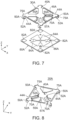
- an antenna device 10A comprises an auxiliary element 80A in addition to a printed circuit board 20A and an antenna element 30A.
- the printed circuit board 20A has a ground conductor 22A.
- the printed circuit board 20A has the ground conductor 22A which is formed on a dielectric substrate. There is no restriction on the size, shape and structure of the printed circuit board 20A, provided that the printed circuit board 20A comprises the ground conductor 22A.
- the antenna element 30A is fixed on the printed circuit board 20A via the auxiliary element 80A.
- the antenna element 30A of the present embodiment has a structure similar to that of the antenna element 30 of the first embodiment shown in each of Figs. 1 to 4 . Accordingly, components of the antenna element 30A of the present embodiment that are same as those of the antenna element 30 of the first embodiment are referred by using reference signs which includes the letter "A” following the same reference signs of the antenna element 30 of the first embodiment.
- reference sign "40A" which includes the letter "A” following the same reference sign "40" of the upper conductor of the antenna element 30 of the first embodiment.
- the antenna element 30A of the present embodiment is dissimilar to the antenna element 30 of the aforementioned first element in that the antenna element 30A of the present embodiment comprises none of a lower conductor and an additional lower conductor. Since the antenna element 30A comprises none of the lower conductor and the additional lower conductor, fixed portions 52A extend directly from the legs 50A, respectively, while fixed portions 57A extend directly from the additional legs 55A, respectively.
- the auxiliary element 80A of the present embodiment is an auxiliary printed circuit board on which the antenna element 30A is mounted and which is fixed on the printed circuit board 20A.
- the auxiliary element 80A has auxiliary first lower electrodes 82A, auxiliary second lower electrodes 84A and feeding pads 86A.
- the auxiliary first lower electrodes 82A, the auxiliary second lower electrodes 84A and the feeding pads 86A are formed on a dielectric substrate.
- the auxiliary first lower electrodes 82A, the auxiliary second lower electrodes 84A and the feeding pads 86A are separated from each other.
- Each of the auxiliary first lower electrodes 82A and the auxiliary second lower electrodes 84A of the present embodiment is left electrically floating. Specifically, each of the auxiliary first lower electrodes 82A and the auxiliary second lower electrodes 84A of the present embodiment is not electrically connected with any other part of the auxiliary element 80A. In contrast, each of the feeding pads 86A is electrically connected to an outside part of the antenna device 10A by unshown means.
- the auxiliary element 80A may further comprise a ground pattern which covers the whole of its lower surface.
- the auxiliary first lower electrodes 82A of Fig.7 correspond to the lower conductors 60, respectively, of Fig. 2 .
- the upper conductor 40A and each of the auxiliary first lower electrodes 82A form a capacitor when the fixed portions 52A are fixed to the auxiliary first lower electrodes 82A, respectively.
- the ground conductor 22A and each of the auxiliary first lower electrodes 82A form another capacitor when the auxiliary element 80A is fixed on the printed circuit board 20A.
- the auxiliary second lower electrodes 84A of Fig. 7 correspond to the additional lower conductors 65, respectively, of Fig. 2 .
- the upper conductor 40A and each of the auxiliary second lower electrodes 84A form a capacitor when the fixed portions 57A are fixed to the auxiliary second lower electrodes 84A, respectively.
- the ground conductor 22A and each of the auxiliary second lower electrodes 84A form another capacitor when the auxiliary element 80A is fixed on the printed circuit board 20A.
- the antenna element 30A of the present embodiment is formed by bending a stamped metal 32A shown in Fig. 10 . That is, as shown in Fig. 10 , a developed plan of the antenna element 30A of the present embodiment has an outer peripheral shape with line symmetry.
- the stamped metal 32A shown therein is a blank which is obtained by punching a metal plate serving as base material.
- the stamped metal 32A has four first portions 34A, four second portions 36A and two third portions 38A in addition to the upper conductor 40A and stubs 75A.
- each of the first portions 34A is a portion which is configured to be bent to form the leg 50A.
- Each of the second portions 36A is a portion which is configured to be bent to form the additional leg 55A.
- Each of the third portions 38A is a portion which is configured to be bent to form the feeding portions 70A.
- the upper conductor 40A of the present embodiment may also be further provided with a dummy slot corresponding to a slot 46A.
- the antenna element 30A of the present embodiment can have increased design flexibility similar to the aforementioned first embodiment.
- the developed plan of the antenna element 30A has the outer peripheral shape with line symmetry and thereby the antenna element 30A lacks rotational symmetry, a provision of recessed portions 44A and the stubs 75A can appropriately compensate the lack of the rotational symmetry of the antenna element 30A. Accordingly, the antenna device 10A using the antenna element 30A can have improved axial ratio characteristics.
- each of the upper conductors 40, 40A of the aforementioned embodiments has the outer periphery with a substantially rectangular shape
- the present invention is not limited thereto.
- the outer periphery of the upper conductor 40, 40A may have another shape, provided that the outer peripheral shape of the upper conductor 40, 40A is line-symmetrical with respect to the line, which passes through the center of the upper conductor 40, 40A, when the upper conductor 40, 40A is viewed in plan view.
- a substantial shape of the outer periphery of the upper conductor 40, 40A may be, for example, a circle, oval or another polygon.
- the shape of the aforementioned specific imaginary rectangle 42, 42A is adjusted to correspond to the substantial shape of the outer periphery of the upper conductor 40, 40A. If the outer periphery of the upper conductor 40, 40A has, for example, a substantially circular shape, a circle that encloses the upper conductor 40, 40A and that is of minimum area should be assumed as a specific imaginary circle corresponding to the specific imaginary rectangle 42, 42A.
- the antenna elements 30, 30A of the aforementioned embodiments are configured so that the leg 50, 50A protrudes in the orientation that is parallel and opposite to the orientation in which the corresponding recessed portion 44, 44A is recessed
- the present invention is not limited thereto.
- the orientation of the leg 50, 50A may not be parallel to and intersect somewhat with the orientation of the corresponding recessed portion 44, 44A, provided that the orientation of the leg 50, 50A is substantially opposite to the orientation of the corresponding recessed portion 44, 44A.
- the antenna element 30, 30A may be configured so that the leg 50, 50A protrudes outward in a radial direction of the substantially circular shape while the corresponding recessed portion 44, 44A is recessed inward in the radial direction.
Landscapes
- Waveguide Aerials (AREA)
- Details Of Aerials (AREA)
Applications Claiming Priority (1)
| Application Number | Priority Date | Filing Date | Title |
|---|---|---|---|
| JP2023089850A JP2024172259A (ja) | 2023-05-31 | 2023-05-31 | アンテナエレメント及びアンテナ装置 |
Publications (2)
| Publication Number | Publication Date |
|---|---|
| EP4471986A1 true EP4471986A1 (de) | 2024-12-04 |
| EP4471986B1 EP4471986B1 (de) | 2026-03-25 |
Family
ID=91247251
Family Applications (1)
| Application Number | Title | Priority Date | Filing Date |
|---|---|---|---|
| EP24177640.0A Active EP4471986B1 (de) | 2023-05-31 | 2024-05-23 | Antennenelement und antennenvorrichtung - ep |
Country Status (4)
| Country | Link |
|---|---|
| US (1) | US12609443B2 (de) |
| EP (1) | EP4471986B1 (de) |
| JP (1) | JP2024172259A (de) |
| CN (1) | CN119070003A (de) |
Citations (4)
| Publication number | Priority date | Publication date | Assignee | Title |
|---|---|---|---|---|
| US20170062933A1 (en) * | 2015-08-26 | 2017-03-02 | The Chinese University Of Hong Kong | Air-filled patch antenna |
| US10096911B2 (en) * | 2015-04-30 | 2018-10-09 | Wistron Neweb Corporation | Dual-band antenna and antenna system |
| EP3832793A1 (de) * | 2019-12-05 | 2021-06-09 | Japan Aviation Electronics Industry, Limited | Antenne |
| JP2022150365A (ja) | 2021-03-26 | 2022-10-07 | 株式会社ヨコオ | アンテナ及びアンテナ装置 |
Family Cites Families (7)
| Publication number | Priority date | Publication date | Assignee | Title |
|---|---|---|---|---|
| JP2005159836A (ja) | 2003-11-27 | 2005-06-16 | Alps Electric Co Ltd | アンテナ装置 |
| JP4882771B2 (ja) | 2007-02-01 | 2012-02-22 | ミツミ電機株式会社 | アンテナ装置 |
| KR102446464B1 (ko) | 2016-02-29 | 2022-09-23 | 타이코에이엠피 주식회사 | 안테나 및 이를 포함하는 안테나 모듈 |
| US10476143B1 (en) * | 2018-09-26 | 2019-11-12 | Lear Corporation | Antenna for base station of wireless remote-control system |
| CN112467343B (zh) | 2019-09-09 | 2023-07-04 | 普罗斯通信技术(苏州)有限公司 | 一种高增益小型化天线振子及天线 |
| CN211670319U (zh) | 2020-04-24 | 2020-10-13 | 瑞典爱立信有限公司 | 天线元件及包括该天线元件的基站天线 |
| EP4354660A1 (de) | 2022-10-12 | 2024-04-17 | Japan Aviation Electronics Industry, Limited | Antennenelement und antennenvorrichtung |
-
2023
- 2023-05-31 JP JP2023089850A patent/JP2024172259A/ja active Pending
-
2024
- 2024-05-18 US US18/668,143 patent/US12609443B2/en active Active
- 2024-05-23 EP EP24177640.0A patent/EP4471986B1/de active Active
- 2024-05-24 CN CN202410658031.XA patent/CN119070003A/zh active Pending
Patent Citations (4)
| Publication number | Priority date | Publication date | Assignee | Title |
|---|---|---|---|---|
| US10096911B2 (en) * | 2015-04-30 | 2018-10-09 | Wistron Neweb Corporation | Dual-band antenna and antenna system |
| US20170062933A1 (en) * | 2015-08-26 | 2017-03-02 | The Chinese University Of Hong Kong | Air-filled patch antenna |
| EP3832793A1 (de) * | 2019-12-05 | 2021-06-09 | Japan Aviation Electronics Industry, Limited | Antenne |
| JP2022150365A (ja) | 2021-03-26 | 2022-10-07 | 株式会社ヨコオ | アンテナ及びアンテナ装置 |
Also Published As
| Publication number | Publication date |
|---|---|
| TW202501877A (zh) | 2025-01-01 |
| US12609443B2 (en) | 2026-04-21 |
| CN119070003A (zh) | 2024-12-03 |
| EP4471986B1 (de) | 2026-03-25 |
| JP2024172259A (ja) | 2024-12-12 |
| US20240405413A1 (en) | 2024-12-05 |
Similar Documents
| Publication | Publication Date | Title |
|---|---|---|
| US6958732B2 (en) | Small-sized and high-gained antenna-integrated module | |
| US7075486B2 (en) | Circularly polarized wave antenna made of sheet metal with high reliability | |
| EP1536511A1 (de) | Antennenvorrichtung | |
| US11223115B2 (en) | Antenna | |
| CN115039288B (zh) | 连接器、连接器模块以及电子设备 | |
| US11380997B2 (en) | Antenna | |
| US11417957B2 (en) | Antenna | |
| EP3506423B1 (de) | Elektronische vorrichtung | |
| US8519896B2 (en) | Antenna having line-shaped electrode on board end surface | |
| EP4471986A1 (de) | Antennenelement und antennenvorrichtung - ep | |
| KR100838407B1 (ko) | 급전 클립 | |
| US9899739B2 (en) | Hybrid antenna | |
| JP5053659B2 (ja) | パッチアンテナ | |
| JP5590252B2 (ja) | 通信モジュール、コネクタ及びコネクタ付き通信モジュール | |
| JP2024166943A (ja) | アンテナ装置、及びアンテナ基板 | |
| TWI920588B (zh) | 天線元件以及天線裝置 | |
| JP3794874B2 (ja) | 送受信ユニット | |
| JP2004328067A (ja) | 平面アンテナ | |
| JP2024126186A (ja) | 周波数共用アンテナ | |
| JPH11251816A (ja) | 表面実装型アンテナおよびそれを搭載した通信機 | |
| JP2024122201A (ja) | ダイポールアンテナ及び周波数共用アンテナ | |
| WO2024075735A1 (ja) | Rfidモジュール | |
| JP2024110611A (ja) | アンテナ装置、及びアンテナ基板 | |
| CN120857387A (zh) | 电子装置 | |
| JP2008079009A (ja) | アンテナ装置 |
Legal Events
| Date | Code | Title | Description |
|---|---|---|---|
| PUAI | Public reference made under article 153(3) epc to a published international application that has entered the european phase |
Free format text: ORIGINAL CODE: 0009012 |
|
| STAA | Information on the status of an ep patent application or granted ep patent |
Free format text: STATUS: THE APPLICATION HAS BEEN PUBLISHED |
|
| AK | Designated contracting states |
Kind code of ref document: A1 Designated state(s): AL AT BE BG CH CY CZ DE DK EE ES FI FR GB GR HR HU IE IS IT LI LT LU LV MC ME MK MT NL NO PL PT RO RS SE SI SK SM TR |
|
| STAA | Information on the status of an ep patent application or granted ep patent |
Free format text: STATUS: REQUEST FOR EXAMINATION WAS MADE |
|
| 17P | Request for examination filed |
Effective date: 20250415 |
|
| STAA | Information on the status of an ep patent application or granted ep patent |
Free format text: STATUS: EXAMINATION IS IN PROGRESS |
|
| 17Q | First examination report despatched |
Effective date: 20250522 |
|
| GRAP | Despatch of communication of intention to grant a patent |
Free format text: ORIGINAL CODE: EPIDOSNIGR1 |
|
| STAA | Information on the status of an ep patent application or granted ep patent |
Free format text: STATUS: GRANT OF PATENT IS INTENDED |
|
| INTG | Intention to grant announced |
Effective date: 20250929 |
|
| GRAS | Grant fee paid |
Free format text: ORIGINAL CODE: EPIDOSNIGR3 |
|
| GRAA | (expected) grant |
Free format text: ORIGINAL CODE: 0009210 |
|
| STAA | Information on the status of an ep patent application or granted ep patent |
Free format text: STATUS: THE PATENT HAS BEEN GRANTED |
|
| AK | Designated contracting states |
Kind code of ref document: B1 Designated state(s): AL AT BE BG CH CY CZ DE DK EE ES FI FR GB GR HR HU IE IS IT LI LT LU LV MC ME MK MT NL NO PL PT RO RS SE SI SK SM TR |
|
| REG | Reference to a national code |
Ref country code: CH Ref legal event code: F10 Free format text: ST27 STATUS EVENT CODE: U-0-0-F10-F00 (AS PROVIDED BY THE NATIONAL OFFICE) Effective date: 20260325 Ref country code: GB Ref legal event code: FG4D |
|
| REG | Reference to a national code |
Ref country code: DE Ref legal event code: R096 Ref document number: 602024003366 Country of ref document: DE |
|
| REG | Reference to a national code |
Ref country code: IE Ref legal event code: FG4D |