EP4470945A1 - Kommissionieranlage - Google Patents
Kommissionieranlage Download PDFInfo
- Publication number
- EP4470945A1 EP4470945A1 EP24178961.9A EP24178961A EP4470945A1 EP 4470945 A1 EP4470945 A1 EP 4470945A1 EP 24178961 A EP24178961 A EP 24178961A EP 4470945 A1 EP4470945 A1 EP 4470945A1
- Authority
- EP
- European Patent Office
- Prior art keywords
- stacking
- piece goods
- picking system
- conveyor
- order picking
- Prior art date
- Legal status (The legal status is an assumption and is not a legal conclusion. Google has not performed a legal analysis and makes no representation as to the accuracy of the status listed.)
- Pending
Links
Images




Classifications
-
- B—PERFORMING OPERATIONS; TRANSPORTING
- B65—CONVEYING; PACKING; STORING; HANDLING THIN OR FILAMENTARY MATERIAL
- B65G—TRANSPORT OR STORAGE DEVICES, e.g. CONVEYORS FOR LOADING OR TIPPING, SHOP CONVEYOR SYSTEMS OR PNEUMATIC TUBE CONVEYORS
- B65G1/00—Storing articles, individually or in orderly arrangement, in warehouses or magazines
- B65G1/02—Storage devices
- B65G1/04—Storage devices mechanical
- B65G1/137—Storage devices mechanical with arrangements or automatic control means for selecting which articles are to be removed
- B65G1/1373—Storage devices mechanical with arrangements or automatic control means for selecting which articles are to be removed for fulfilling orders in warehouses
- B65G1/1376—Storage devices mechanical with arrangements or automatic control means for selecting which articles are to be removed for fulfilling orders in warehouses the orders being assembled on a commissioning conveyor
-
- B—PERFORMING OPERATIONS; TRANSPORTING
- B07—SEPARATING SOLIDS FROM SOLIDS; SORTING
- B07C—POSTAL SORTING; SORTING INDIVIDUAL ARTICLES, OR BULK MATERIAL FIT TO BE SORTED PIECE-MEAL, e.g. BY PICKING
- B07C5/00—Sorting according to a characteristic or feature of the articles or material being sorted, e.g. by control effected by devices which detect or measure such characteristic or feature; Sorting by manually actuated devices, e.g. switches
- B07C5/36—Sorting apparatus characterised by the means used for distribution
- B07C5/38—Collecting or arranging articles in groups
-
- B—PERFORMING OPERATIONS; TRANSPORTING
- B65—CONVEYING; PACKING; STORING; HANDLING THIN OR FILAMENTARY MATERIAL
- B65B—MACHINES, APPARATUS OR DEVICES FOR, OR METHODS OF, PACKAGING ARTICLES OR MATERIALS; UNPACKING
- B65B35/00—Supplying, feeding, arranging or orientating articles to be packaged
- B65B35/30—Arranging and feeding articles in groups
- B65B35/32—Arranging and feeding articles in groups by gravity
-
- B—PERFORMING OPERATIONS; TRANSPORTING
- B65—CONVEYING; PACKING; STORING; HANDLING THIN OR FILAMENTARY MATERIAL
- B65B—MACHINES, APPARATUS OR DEVICES FOR, OR METHODS OF, PACKAGING ARTICLES OR MATERIALS; UNPACKING
- B65B35/00—Supplying, feeding, arranging or orientating articles to be packaged
- B65B35/30—Arranging and feeding articles in groups
- B65B35/50—Stacking one article, or group of articles, upon another before packaging
-
- B—PERFORMING OPERATIONS; TRANSPORTING
- B65—CONVEYING; PACKING; STORING; HANDLING THIN OR FILAMENTARY MATERIAL
- B65G—TRANSPORT OR STORAGE DEVICES, e.g. CONVEYORS FOR LOADING OR TIPPING, SHOP CONVEYOR SYSTEMS OR PNEUMATIC TUBE CONVEYORS
- B65G1/00—Storing articles, individually or in orderly arrangement, in warehouses or magazines
- B65G1/02—Storage devices
- B65G1/04—Storage devices mechanical
- B65G1/137—Storage devices mechanical with arrangements or automatic control means for selecting which articles are to be removed
- B65G1/1373—Storage devices mechanical with arrangements or automatic control means for selecting which articles are to be removed for fulfilling orders in warehouses
- B65G1/1378—Storage devices mechanical with arrangements or automatic control means for selecting which articles are to be removed for fulfilling orders in warehouses the orders being assembled on fixed commissioning areas remote from the storage areas
-
- B—PERFORMING OPERATIONS; TRANSPORTING
- B65—CONVEYING; PACKING; STORING; HANDLING THIN OR FILAMENTARY MATERIAL
- B65G—TRANSPORT OR STORAGE DEVICES, e.g. CONVEYORS FOR LOADING OR TIPPING, SHOP CONVEYOR SYSTEMS OR PNEUMATIC TUBE CONVEYORS
- B65G47/00—Article or material-handling devices associated with conveyors; Methods employing such devices
- B65G47/52—Devices for transferring articles or materials between conveyors i.e. discharging or feeding devices
- B65G47/60—Devices for transferring articles or materials between conveyors i.e. discharging or feeding devices to or from conveyors of the suspended, e.g. trolley, type
-
- B—PERFORMING OPERATIONS; TRANSPORTING
- B65—CONVEYING; PACKING; STORING; HANDLING THIN OR FILAMENTARY MATERIAL
- B65G—TRANSPORT OR STORAGE DEVICES, e.g. CONVEYORS FOR LOADING OR TIPPING, SHOP CONVEYOR SYSTEMS OR PNEUMATIC TUBE CONVEYORS
- B65G47/00—Article or material-handling devices associated with conveyors; Methods employing such devices
- B65G47/52—Devices for transferring articles or materials between conveyors i.e. discharging or feeding devices
- B65G47/60—Devices for transferring articles or materials between conveyors i.e. discharging or feeding devices to or from conveyors of the suspended, e.g. trolley, type
- B65G47/61—Devices for transferring articles or materials between conveyors i.e. discharging or feeding devices to or from conveyors of the suspended, e.g. trolley, type for articles
-
- B—PERFORMING OPERATIONS; TRANSPORTING
- B65—CONVEYING; PACKING; STORING; HANDLING THIN OR FILAMENTARY MATERIAL
- B65G—TRANSPORT OR STORAGE DEVICES, e.g. CONVEYORS FOR LOADING OR TIPPING, SHOP CONVEYOR SYSTEMS OR PNEUMATIC TUBE CONVEYORS
- B65G57/00—Stacking of articles
- B65G57/02—Stacking of articles by adding to the top of the stack
- B65G57/03—Stacking of articles by adding to the top of the stack from above
- B65G57/06—Gates for releasing articles
-
- B—PERFORMING OPERATIONS; TRANSPORTING
- B65—CONVEYING; PACKING; STORING; HANDLING THIN OR FILAMENTARY MATERIAL
- B65G—TRANSPORT OR STORAGE DEVICES, e.g. CONVEYORS FOR LOADING OR TIPPING, SHOP CONVEYOR SYSTEMS OR PNEUMATIC TUBE CONVEYORS
- B65G61/00—Use of pick-up or transfer devices or of manipulators for stacking or de-stacking articles not otherwise provided for
-
- B—PERFORMING OPERATIONS; TRANSPORTING
- B65—CONVEYING; PACKING; STORING; HANDLING THIN OR FILAMENTARY MATERIAL
- B65G—TRANSPORT OR STORAGE DEVICES, e.g. CONVEYORS FOR LOADING OR TIPPING, SHOP CONVEYOR SYSTEMS OR PNEUMATIC TUBE CONVEYORS
- B65G21/00—Supporting or protective framework or housings for endless load-carriers or traction elements of belt or chain conveyors
- B65G21/10—Supporting or protective framework or housings for endless load-carriers or traction elements of belt or chain conveyors movable, or having interchangeable or relatively movable parts; Devices for moving framework or parts thereof
- B65G21/14—Supporting or protective framework or housings for endless load-carriers or traction elements of belt or chain conveyors movable, or having interchangeable or relatively movable parts; Devices for moving framework or parts thereof to allow adjustment of length or configuration of load-carrier or traction element
-
- B—PERFORMING OPERATIONS; TRANSPORTING
- B65—CONVEYING; PACKING; STORING; HANDLING THIN OR FILAMENTARY MATERIAL
- B65G—TRANSPORT OR STORAGE DEVICES, e.g. CONVEYORS FOR LOADING OR TIPPING, SHOP CONVEYOR SYSTEMS OR PNEUMATIC TUBE CONVEYORS
- B65G47/00—Article or material-handling devices associated with conveyors; Methods employing such devices
- B65G47/52—Devices for transferring articles or materials between conveyors i.e. discharging or feeding devices
- B65G47/68—Devices for transferring articles or materials between conveyors i.e. discharging or feeding devices adapted to receive articles arriving in one layer from one conveyor lane and to transfer them in individual layers to more than one conveyor lane or to one broader conveyor lane, or vice versa, e.g. combining the flows of articles conveyed by more than one conveyor
- B65G47/71—Devices for transferring articles or materials between conveyors i.e. discharging or feeding devices adapted to receive articles arriving in one layer from one conveyor lane and to transfer them in individual layers to more than one conveyor lane or to one broader conveyor lane, or vice versa, e.g. combining the flows of articles conveyed by more than one conveyor the articles being discharged or distributed to several distinct separate conveyors or to a broader conveyor lane
Definitions
- the present invention relates to an order picking system with a stacking device for vertically stacking piece goods.
- EP4001188A1 published on 25.05.2022 in the name of Siemens AG, discloses an end point device for a sorting system for sorting piece goods, comprising a receiving device, a transport device and a row arrangement of end points arranged in a row, wherein the receiving device is designed to receive a piece of goods from a sorter output of a sorter of the sorting system and to deliver it to the transport device, wherein the transport device comprises a transport unit which can be moved to each of the end points arranged in the row and wherein the transport device is designed to receive the piece of goods delivered by the receiving device and to transport it with the transport unit to a desired end point of the end points arranged in the row and to deliver it to this desired end point.
- EP1253098A1 published on 30.10.2002 in the name of Grapha Holding, discloses a device for processing printed products fed to a stacking device, which are picked up at a delivery of a printing press or a print processing machine by a conveyor device for hanging further transport and are fed via a conveyor path to a transfer device upstream of the stacking device.
- the stacking device is designed as a unit that can be detached from the transfer device and can optionally be connected to the transfer device that is connected to the printing press or the print processing machine in a conveying manner.
- DE20019292U1 published on March 29, 2001 in the name of PSB GmbH, discloses a device for sorting and stacking piece goods, which comprises a controllable feed conveyor for the goods to be sorted, a distribution device with a plurality of movable goods receptacles rotating in a circle about a central axis, devices for the controlled discharge of the goods to be sorted from the goods receptacle, a target point for forming a stack of goods to be sorted, wherein the feed conveyor transfers the goods to be sorted approximately tangentially to the goods receptacles, which are implemented as a controllable conveyor device and the target points are located under the goods receptacles, wherein a controllable storage area is located between the goods receptacles and each target point, wherein the goods receptacles each discharge the goods to be sorted onto a storage area by conveying the goods to be sorted against the direction of rotation.
- B2B business-to-business
- B2C business-to-customer
- General cargo can be a very wide range of products. For example, both inherently stable products such as packages, boxes or books as well as flexible and essentially flat general cargo such as magazines or even individual loose items of clothing that are only packaged in a flexible protective cover must be picked at the same time.
- One object of the invention can be seen in providing an order picking system that enables the space-saving provision of consignments of goods with a wide variety of product categories.
- An order picking system is used for transporting and stacking piece goods.
- the order picking system typically comprises a conveyor device and a stacking device.
- Piece goods can be a very wide range of products. For example, inherently stable products such as packages, boxes or books are possible. On the other hand, however, flexible and essentially flat piece goods such as magazines or even items of clothing can also be stacked.
- stacking or piling is to be understood as the preferably vertical piling of piece goods arranged loosely on top of one another.
- a stack is to be understood here as a preferably neatly stacked pile or heap that comprises a plurality of piece goods. The piece goods can be stacked on top of one another without a fixed alignment, thereby forming the stack.
- the conveying device comprises an overhead conveyor for conveying the piece goods, as well as a delivery station for delivering the piece goods from the overhead conveyor to the stacking device.
- the piece goods are preferably delivered to the delivery station hanging in hanging bags and emptied by the delivery station and transferred to the stacking device located downstream.
- the overhead conveyor typically comprises at least one rail on which the hanging bags can be conveyed hanging by means of a carriage.
- the overhead conveyor can also comprise baskets, bags or carrying straps by means of which the piece goods can be conveyed hanging.
- the hanging pockets may comprise a rear wall and a front wall which are flexibly connected to one another via a base section such that they can be moved back and forth between a first state in which they form an open and fillable bag and a second state in which they lie close together and form a folded bag.
- the overhead conveyor can be connected to the conveying device, which preferably comprises a delivery station in the form of an emptying device.
- the overhead conveyor or several overhead conveyors can connect the stacking device to devices arranged upstream. Using the overhead conveyor, a delivery can be combined with a removal within a logistics facility and the flow of goods can thus be established.
- the emptying device can comprise a rotating conveyor belt for receiving piece goods transported in the hanging bags.
- the conveying path of the hanging conveyor and the conveying path of the conveyor belt can be arranged in such a way that the distance between the conveying path of the hanging conveyor and the conveying path of the conveyor belt continuously decreases, so that when a hanging bag is conveyed along the contact section, a front side of the hanging bag contacts the conveyor belt and comes to rest on it, and the hanging bag is pivoted backwards.
- the conveying path of the overhead conveyor and the conveying path of the conveyor belt can run essentially parallel to each other with a certain downward gradient, whereby the front of the respective overhead pocket continues to rest on the Conveyor belt so that the opening of the hanging pocket is oriented diagonally downwards and piece goods in the hanging pocket slide out of the pocket, preferably by gravity, onto the conveyor belt.
- the distance between the conveying path of the overhead conveyor and the conveying path of the conveyor belt can become continuously larger, so that when a hanging bag is conveyed along the separation section, the emptied hanging bag is lifted off the conveyor belt and swings back into the freely hanging position.
- the conveying speeds of the conveyor belt and those of the overhead conveyor are usually the same.
- the conveyor belt can have a plurality of outwardly directed transverse ribs arranged at equal distances along a circumference of the conveyor belt.
- the relative position of the ribs and the hanging pockets is typically selected such that in the contact section a rib catches up with the hanging pocket, contacts the bottom section of the hanging pocket and pushes it forward in the conveying direction until the hanging pocket has entered a state for emptying.
- the overhead conveyor and the conveyor belt can be operated at the same speed.
- the overhead conveyor and the conveyor belt can run constantly at the same speed.
- the distance between the ribs can be selected so that during the conveying of a hanging bag along the transfer section, existing Items slide out of the pocket onto the conveyor belt using gravity and then slide further down the conveyor belt using gravity until they are caught and held by the rib in front of the hanging pocket.
- the ribs of the conveyor belt can consist of a large number of parallel fingers.
- An upper end of the chute can have slots whose position corresponds to the fingers of the ribs of the conveyor belt, so that when the conveyor belt is deflected, the fingers of the ribs and the slots of the chute interact with each other and piece goods held back behind a rib are released in a timed manner, which are then conveyed further on the chute by gravity.
- Another conveyor can take over the released piece goods units from the chute.
- vibration means can be provided with which the surface of the conveyor belt can be set into vibration or oscillation in at least a partial section of the conveyor belt.
- the hanging bags can be emptied using the delivery station and the items can be transferred either directly to the stacking device or to a conveyor and then to the stacking device using the conveyor. While inherently stable While general cargo is transported essentially upright in the hanging bag during transport and flexible general cargo is transported folded in the west, it is handed over lying down from the delivery station.
- the term “lying” is to be understood as meaning an essentially horizontal orientation of the piece goods, in which the piece goods lie with their base in a horizontal position on the conveyor or stacking device.
- the latter can have a stop.
- the stacking device can include a stop for positioning the piece of goods delivered by the delivery device. This can be designed, for example, as a guide plate or angle that deflects the piece of goods and positions them on the delivery station.
- An optionally arranged conveyor between the delivery station and the stacking device can be operated in stop-and-go mode and/or can be accelerated or braked in order to be able to transfer the respective piece goods to the stacking device individually.
- the conveyor can be a telescopic belt that has a movable end.
- the piece goods can be transferred centrally to the stacking device using the movable end.
- a sensor preferably an optical sensor, can be used to determine the position in order to be able to transfer the piece goods centrally onto the stacking device.
- the conveyed piece goods can be stacked vertically on a stacking station using the stacking device.
- the stacking station can be designed in the form of a physical station, for example as a stacking station on the floor or on a pallet.
- the stacking station can also be a virtual stacking station in the form of a belt section or a conveyor unit such as a conveyor tray.
- the stacking device can, for example, comprise a discharge conveyor and the stacking station can be arranged on the discharge conveyor so that the stack can be discharged using the discharge conveyor.
- the discharge conveyor can be a roller, belt or tray conveyor.
- the delivery device is typically vertically offset, arranged above the stacking area, and the piece goods can be transferred to form a free stack.
- the stacking device can comprise a lifting device that is arranged below the delivery device and can be moved vertically in the direction of the stacking area or the removal conveyor. After a piece of goods has been delivered from the stacking device to the lifting device, it is typically moved further before the next piece of goods is transferred.
- the lifting device can, for example, be designed as a lifting table with a fixed plate that can be moved in a vertical direction. To make it easier to remove the stacked stack, the lifting device can also comprise a conveyor belt instead of the plate.
- the stacking device can comprise at least one delivery device, by means of which one piece of goods can be released after the other and transferred to the stacking area by gravity to form a stack.
- the piece of goods can also be stacked directly into a transport container, such as boxes, sacks or cartons.
- the aim is usually to deliver the piece goods as centrally as possible to the stacking area.
- the delivery device can have at least one delivery element that is arranged to be movable or pivotable so that the respective piece goods can be transferred to the stacking area using the delivery element.
- the delivery device can also comprise two or more delivery elements, which can preferably be moved or pivoted symmetrically. These can be designed as sliders that can be moved horizontally. This creates a gap through which the piece goods can be transferred to the stacking area by gravity.
- the two delivery elements can be designed as flaps, the opposite ends of which can be pivoted in the direction of the stacking area. Pivoting in the direction of the stacking area creates a funnel-shaped delivery surface over which the piece goods are centered and can therefore be transferred centrally.
- the delivery device comprises four essentially triangular flaps, which form a funnel when pivoted in order to align the piece goods when transferred and transfer them centrally.
- the two delivery elements can be designed as cross conveyors which can be driven and accelerated or braked and can be moved horizontally, preferably in opposite directions, along a conveying direction.
- the cross conveyors can each have a movable end and a fixed end, and by moving the movable ends in opposite directions along the conveying direction, a gap can be generated through which a piece of goods can be delivered to the stacking area.
- a gap remains. However, this gap is chosen to be so small that none of the piece of goods to be conveyed can fall through.
- a gap can be generated that is so large that the piece of goods to be transferred can be transferred through the gap to the stacking area or stack.
- the respective piece goods can be moved or aligned using the cross conveyors.
- the conveyor can comprise at least two conveyor lines and the movable ends of the cross conveyors can each be moved along the conveying direction in such a way that the gap above a stacking location can be positioned and generated on one of the at least two conveyor lines.
- the piece goods on the cross conveyors can thus be positioned over one of the two conveyor lines and by moving the movable ends of the cross conveyors in opposite directions, the gap can be adjusted to be so large that the piece goods can be transferred to one of the two conveyor lines.
- the order picking system can include a measuring device for measuring the height of the stack and/or for detecting whether a piece of goods is on the delivery device. On the one hand, this can be used to determine when the target or maximum height of the stack has been reached and the stack can be removed. On the other hand, the delivery device can be controlled using the measurement data recorded by the measuring device.
- the order picking system can include a monitoring device that can be used to monitor the layout of the stack in a top view and/or the outline of the stack in a side view. This ensures that stacks that are becoming unstable can be detected and recognized early on.
- the layout is the outline of the stack in a top view of the stack. This can also be used to detect stacks that would exceed the permissible dimensions of downstream devices in terms of their layout and can therefore be eliminated early on.
- the vertical alignment of the stack can also be monitored.
- the stack should also not exceed a certain level of lateral runout in order to avoid becoming too unstable.
- the monitoring device can determine measurement data by means of at least one sensor, preferably an optical sensor, when stacking and/or when the stack moves past the sensor.
- an imaging sensor preferably a laser grid or a Light barrier can be used.
- An optical proximity sensor can be used to monitor the lateral runout.
- the stacking device can comprise at least one delivery device by means of which one piece of goods is released one after the other and is transferred to the stacking area by gravity to form a stack.
- the at least one delivery device can have two delivery elements which are moved or pivoted, preferably folded, in order to transfer the respective piece goods to the stacking area.
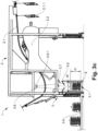
- Figures 1a to 1c show a first variant of the order picking system 1 for the transport and stacked provision of piece goods W.
- Figure 1a shows the order picking system 1 with a conveying device 2 for conveying the piece goods W, which for this purpose comprises an overhead conveyor 2.1.
- the overhead conveyor 2.1 shown comprises hanging pockets 2.1.1 for conveying the piece goods W.
- the overhead conveyor 2.1 can also comprise baskets, bags or carrying straps, by means of which the piece goods W can be conveyed in a hanging manner.
- the conveyor device 2 shown also includes a delivery station 2.2 for delivering the piece goods W from the overhead conveyor 2.1.
- the delivery station 2.2 of the conveyor device 2 shown is designed as an emptying device 2.2.1.
- the piece goods W delivered from the emptying device 2.2.1 to the stacking device 3 by means of a telescopic belt 2.2.2 can be stacked using this.
- the piece goods W are stacked vertically using the stacking device 3 on a stacking location 3.1 on a discharge conveyor 3.4.
- Figure 1b shows the transfer of the piece goods W to the stacking device 3.
- the delivery device 3.2 shown is vertically offset, arranged above the stacking location 3.1 and transfers the piece goods W to form a free stack S.
- the piece goods W are transferred centrally to the stacking device 3 by means of the telescopic belt 2.2.2.
- the stacking device 3 shown comprises a delivery device 3.2, by means of which one piece of goods W can be released after the other and transferred to the stacking location 3.1 by gravity to form a stack S.
- the delivery device 3.2 shown has two delivery elements 3.2.1, which are arranged to be pivotable, in the embodiment shown pivotable symmetrically, so that the respective piece of goods W can be transferred to the stacking location 3.1 by means of the two delivery elements 3.2.1 and the stacked stack S can be removed by means of the removal conveyor 3.4.
- Figure 1c shows the stacking of the piece goods W by means of the stacking device 3.
- the two delivery elements 3.2.1 shown which are designed as flaps 3.2.3, whose opposite ends 3.2.4 can be pivoted in the direction of the stacking location 3.1 and are pivoted to release the piece goods W.
- the two delivery elements 3.2.1 can also be designed as sliders 3.2.2, which can be moved horizontally to release the piece goods W.
- a funnel-shaped delivery area is created, as can be seen in the illustration, over which the piece goods W are centered and can thus be transferred centrally.
- the stacking device 3 shown comprises a discharge conveyor 3.4, so that the stack S can be discharged using the discharge conveyor 3.4.
- the discharge conveyor 3.4 shown is a roller conveyor, but can also be a belt or tray conveyor.
- Figures 2a to 2c show a second variant of the order picking system 1 with a lifting device 3.5.
- Figure 2a shows the conveying of the piece goods W.
- the conveying device 2 shown also includes a delivery station 2.2 for delivering the piece goods W from the hanging pockets 2.1.1 of the hanging conveyor 2.1.
- the emptying device 2.2.1 transfers the piece goods W directly to the stacking device 3.
- the emptying device 2.2.1 of the embodiment shown is not connected to the stacking device 3 by means of a telescopic belt, but instead transfers the piece goods W directly to the stacking device 3.
- Figure 2b shows the transfer of the piece goods W to the stacking device 3.
- the delivery device 3.2 shown is vertically offset, arranged above the stacking location 3.1 and transfers the piece goods W to the lifting device 3.5 to form a stack S.
- the stacking device 3 shown comprises a lifting device 3.5, which is arranged below the delivery device 3.2 and can be moved vertically in the direction of the conveyor 3.4.
- the stacking device 3 also comprises a stop 3.6 for positioning the piece goods W delivered by the delivery device 3.2. After a piece of goods W has been delivered from the stacking device 3 to the lifting device 3.5, it is typically moved further before the next piece of goods W is transferred.
- Figure 2c shows the stacking of the piece goods W by means of the stacking device 3.
- the stacking device 3 shown comprises a conveyor 3.4, so that the stack S can be removed by means of the conveyor 3.4.
- the conveyor 3.4 shown is a belt conveyor, but can also be a roller, plate or tray conveyor, for example.
- Figures 3a to 3c show a third variant of the order picking system 1 with a measuring device 3.7.
- Figure 3a shows the conveyance of the piece goods W.
- the two delivery elements 3.2.1 shown are also designed as flaps 3.2.3, the opposite ends 3.2.4 of which can be pivoted in the direction of the stacking area 3.1 in order to release the piece goods W.
- the two delivery elements 3.2.1 can also be designed as sliders, which can be moved horizontally in order to release the piece goods W.
- the order picking system 1 shown comprises a measuring device 3.7 and a monitoring device 3.8 with a sensor 3.8.1.
- the measuring device 3.7 can be used to detect whether a piece of goods W is on the delivery device 3.2.
- Figure 3b shows the transfer of the piece goods W to the stacking device 3.
- the piece goods W are picked into bag B.
- the picking system 3 shown comprises a monitoring device 3.8, by means of which the outline G of the stack S can be monitored in a top view and/or the outline of the stack S in a side view.
- the monitoring device 3.8 can determine the measurement data by means of the sensor 3.8.1, preferably an optical sensor, when stacking and/or when the stack S moves past the sensor 3.8.1.
- Figure 3c shows the stacking of the piece goods W using the stacking device 3.
- the height H of the stack S can be measured. On the one hand, this can be used to determine when the target or maximum height of the stack S has been reached and the stack S is to be removed.
- the dispensing device 3.2 can be controlled by means of the measurement data recorded by the measuring device 3.7.
- Figure 4 shows a fourth variant of the order picking system 1.
- the two delivery elements 3.2.1 are designed as cross conveyors 3.2.5, which can be driven and accelerated or braked and can be moved horizontally, preferably in opposite directions, along a conveying direction F.
- the cross conveyors 3.2.5 each have a movable end 3.2.6 and a fixed end 3.2.7 and by moving the movable ends 3.2.6 in opposite directions along the conveying direction F, a gap can be generated through which a piece of goods W can be delivered to the stacking area 3.1.
- the respective piece of goods W can be moved or aligned using the cross conveyors 3.2.5.
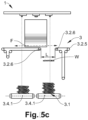
- Figures 5a to 5c show a fifth variant of the order picking system 1.
- FIG. 5a shows the conveying of the piece goods W.
- the discharge conveyor 3.4 of the order picking system 1 shown comprises two discharge conveyor lines 3.4.1, wherein the movable ends 3.2.6 of the cross conveyors 3.2.5 can each be moved along the conveying direction F in such a way that the gap above a stacking location 3.1 can be generated on one of the two discharge conveyor lines 3.4.1.
- the order picking system 1 comprises a measuring device 3.7 for measuring the height of the stack S and for detecting whether a piece of goods W is on the delivery device 3.2. In addition to determining when the target or maximum height of the stack S is reached and the stack S can be transported away, the exact position of the piece of goods W on the cross conveyors 3.2.5 can also be determined.
- the monitoring device 3.8 the outline of the stack G can be monitored in a top view and/or the outline U of the stack S in a side view.
- Figure 5b shows the provision of the piece goods W via one of the conveyor lines 3.4.1.
- the movable ends 3.2.6 of the cross conveyors 3.2.5 are each moved along the conveying direction F in such a way that the piece goods W are positioned above a stacking area 3.1 and are transferred to one of the at least two discharge conveyor lines 3.4.1 by generating the gap.
- the cross conveyors 3.2.5 therefore function as a distribution device, whereby the piece goods W conveyed via the delivery station can be divided between the two conveyor lines 3.4.1.
- Figure 5c shows the stacking of the piece goods W by means of the stacking device 3.
- the movable ends 3.2.6 of the cross conveyors 3.2.5 are each moved along the conveying direction F in such a way that the gap L can be positioned and generated above a stacking location 3.1 on one of the at least two discharge conveyor lines 3.4.1.
Landscapes
- Engineering & Computer Science (AREA)
- Mechanical Engineering (AREA)
- Stacking Of Articles And Auxiliary Devices (AREA)
- Specific Conveyance Elements (AREA)
Abstract
Die vorliegende Erfindung betrifft eine Kommissionieranlage (1) zum Transport und dem gestapelten Bereitstellen von Stückgütern (W) umfassend eine Anfördervorrichtung (2) umfassend einen Hängeförderer (2.1) zum Anfördern der Stückgüter (W) sowie eine Abgabestation (2.2) zum Abgeben der Stückgüter (W) vom Hängeförderer (2.1) an eine Stapelvorrichtung (3) zum Aufstapeln der angeförderten Stückgüter (W), wobei die Stückgüter (W) mittels der Stapelvorrichtung (3) auf einem Stapelplatz (3.1) vertikal aufstapelbar sind.


Description
- Die vorliegende Erfindung betrifft eine Kommissionieranlage mit einer Stapelvorrichtung zum vertikalen Aufstapeln von Stückgütern.
- Aus dem Stand der Technik sind unter anderem die folgenden Kommissionieranlagen bekannt.
-
EP4001188A1, veröffentlicht am 25.05.2022 im Namen der Siemens AG, offenbart eine Endstellenvorrichtung für eine Sortieranlage zum Sortieren von Stückgütern, umfassend eine Aufnahmevorrichtung, eine Transportvorrichtung und eine Reihenanordnung von in einer Reihe angeordneten Endstellen, wobei die Aufnahmevorrichtung ausgestaltet ist ein Stückgut von einem Sorterausgang eines Sorters der Sortieranlage zu übernehmen und an die Transportvorrichtung abzugeben, wobei die Transportvorrichtung eine Transporteinheit umfasst, die zu jeder der in der Reihe angeordneten Endstellen bewegbar ist und wobei die Transportvorrichtung ausgestaltet ist, das von der Aufnahmevorrichtung abgegebene Stückgut zu übernehmen und mit der Transporteinheit an eine gewünschte Endstelle der in der Reihe angeordneten Endstellen zu transportieren und in diese gewünschte Endstelle abzugeben. -
EP1253098A1, veröffentlicht am 30.10.2002 im Namen der Grapha Holding, offenbart eine Einrichtung zur Verarbeitung von einer Stapelvorrichtung zugeführten Druckerzeugnissen, die an einer Auslage einer Druckmaschine oder einer Druckverarbeitungsmaschine von einer Fördervorrichtung zum hängenden Weitertransport erfasst und über einen Förderpfad einer der Stapelvorrichtung vorgeschalteten Überführungsvorrichtung zugeführt werden. Die Stapelvorrichtung ist als von der Überführungsvorrichtung lösbare Einheit ausgebildet und wahlweise an die mit der Druckmaschine oder der Druckverarbeitungsmaschine förderwirksam verbundene Überführungsvorrichtung anschliessbar. -
DE20019292U1, veröffentlicht am 29.03.2001 im Namen der PSB GmbH, offenbart eine Vorrichtung zum Sortieren und Stapeln von Stückgütern, welche einen steuerbaren Zuförderer für das Sortiergut, eine Verteilvorrichtung mit einer Mehrzahl von beweglichen, im Kreise um eine zentrale Achse rotierenden Gutaufnahmen, Einrichtungen zum gesteuerten Ausschleusen des Sortierguts aus der Gutaufnahme, eine Zielstelle zur Bildung eines Stapels aus Sortiergütern umfasst, wobei der Zuförderer die Sortiergüter etwa tangential auf die Gutaufnahmen übergibt, die als steuerbare Fördereinrichtung realisiert sind und sich die Zielstellen unter den Gutaufnahmen befinden, wobei zwischen den Gutaufnahmen und jeder Zielstelle sich eine steuerbare Ablage befindet, wobei die Gutaufnahmen das Sortiergut jeweils auf eine Ablage aus schleusen, indem sie das Sortiergut entgegen der Rotationsrichtung fördern. - Im Bereich der Kommissionierung von Stückgütern wird insbesondere bei Business to Customer (B2C) Kommissionierungen bei der Auftragsabwicklung oder Bestellabwicklung gefordert, in ein und derselben Anlage diverse Arten von Stückgütern verarbeiten zu können. Das Ziel ist ausgangsseitig der Kommissionieranlage versandfertige Bestellungen bereitstellen zu können. Typischerweise werden die Waren in festen Gebinden wie etwa Kartonagen versandt. Die Kundenbestellung soll daher ausgangsseitig der Kommissionieranlage möglichst platzsparend für die Verpackung bereitgestellt werden.
- Während es bei Bestellungen im Business to Business (B2B) Bereich weniger Bestellungen aber hierfür mit grossem Volumen und gleichen Produktfolgen gibt, da Unternehmen Produkte typischerweise in grossen Stückzahlen anfordern, gibt es im Business to Customer (B2C) Bereich typischerweise viele Einzelbestellungen mit Einzelabgaben der Waren oder kleinen Volumen und kleinen Stückzahlen, die zudem auch noch saisonbedingt hohe Fluktuationen aufweisen können.
- Stückgüter können hierbei eine sehr grosse Bandbreite an Produkten sein. Beispielsweise müssen gleichzeitig sowohl eigenstabile Produkte, wie etwa Pakete, Boxen oder Bücher, als auch flexible und im Wesentlichen flache Stückgüter wie etwa Magazine oder gar einzelne lose und nur mit einer flexiblen Schutzhülle verpackte Kleidungsstücke kommissioniert werden.
- Eine Aufgabe der Erfindung kann darin gesehen werden eine Kommissionieranlage bereitzustellen, die das platzsparende Bereitstellen von Warensendungen mit unterschiedlichsten Produktkategorien ermöglicht.
- Eine erfindungsgemässe Kommissionieranlage dient dem Transport und dem gestapelten Bereitstellen von Stückgütern. Die Kommissionieranlage umfasst typischerweise eine Anfördervorrichtung und eine Stapelvorrichtung. Stückgüter können hierbei eine sehr grosse Bandbreite an Produkten sein. Beispielsweise kommen eigenstabile Produkte, wie etwas Pakte, Boxen oder Bücher in Frage. Andererseits können jedoch auch flexible und im Wesentlichen flache Stückgüter wie etwa Magazine oder gar Kleidungsstücke gestapelt werden. Im Kontext dieser Offenbarung ist unter Stapeln oder Aufstapeln das vorzugsweise vertikale Aufschichten von lose übereinander angeordneter Stückgüter zu verstehen. Ein Stapel ist hierbei als ein, vorzugsweise ordentlich, aufgeschichteter Stoss oder Haufen zu verstehen, der eine Mehrzahl an Stückgütern umfasst. Die Stückgüter können hierbei ohne eine feste Ausrichtung aufeinander aufgestapelt werden, wodurch der Stapel ausgebildet wird.
- Die Anfördervorrichtung umfasst einen Hängeförderer zum Anfördern der Stückgüter, sowie eine Abgabestation zum Abgeben der Stückgüter vom Hängeförderer an die Stapelvorrichtung. Die Stückgüter werden dabei vorzugsweise in Hängetaschen hängend an die Abgabestation angeliefert und mittels der Abgabestation entleert und an die stromabwärts gelegene Stapelvorrichtung übergeben. Der Hängeförderer umfasst hierbei typischerweise mindestens eine Schiene, an der die Hängetaschen mittels Laufwagen hängend förderbar sind. Alternativ kann der Hängeförderer auch Körbe, Beutel oder Tragschlaufen umfassen mittels derer die Stückgüter hängend förderbar sind.
- Die Hängetaschen können eine Rückwand und eine Vorderwand umfassen, die über einen Bodenabschnitt derart flexibel miteinander verbunden sind, dass sie zwischen einem ersten Zustand, in welchem sie eine offene und befüllbare Tasche bilden, und einem zweiten Zustand, in welchem sie dicht nebeneinanderliegen und eine zusammengeklappte Tasche bilden, hin und her bewegbar sind.
- Der Hängeförderer kann an die Anfördervorrichtung anschliessen, die vorzugsweise eine Abgabestation in Form einer Entleerungsvorrichtung umfasst. Der Hängeförderer oder auch mehrere Hängeförderer können hierbei die Stapelvorrichtung mit stromaufwärts angeordneten Vorrichtungen verbinden. Mittels des Hängeförderers kann eine Anlieferung mit einem Abtransport innerhalb einer Logistikanlage verbindbar sein und hierdurch den Warenfluss herstellbar sein.
- Die Entleerungsvorrichtung kann ein umlaufendes Förderband zur Übernahme von in den Hängetaschen transportierten Stückgütern umfassen. An einem Kontaktabschnitt kann der Förderweg des Hängeförderers und der Förderweg des Förderbands derart zueinander angeordnet sein, dass der Abstand des Förderwegs des Hängeförderers und des Förderwegs des Förderbands kontinuierlich kleiner wird, so dass bei der Förderung einer Hängetasche entlang des Kontaktabschnitts eine Vorderseite der Hängetsche das Förderband kontaktiert und auf diesem zu liegen kommt und dabei die Hängetasche nach hinten geschwenkt wird.
- In einem Übergabeabschnitt kann der Förderweg des Hängeförderers und der Förderweg des Förderbands im Wesentlichen parallel zueinander mit einem gewissen Gefälle nach unten verlaufen, wobei die Vorderseite der jeweiligen Hängetasche bei der Förderung entlang des Übergabeanschnitts weiterhin auf dem Förderband liegt, so dass die Öffnung der Hängetasche schräg nach unten orientiert ist und in der Hängetasche vorhandene Stückgüter aus der Tasche, vorzugsweise schwerkraftgetrieben, auf das Förderband gleiten.
- In einem Trennabschnitt kann der Abstand des Förderwegs des Hängeförderers und des Förderwegs des Förderbands kontinuierlich grösser werden, so dass bei der Förderung einer Hängetasche entlang des Trennabschnitts die entleerte Hängetasche vom Förderband abgehoben wird und in die frei hängende Lage zurückschwenkt. Üblicherweise sind die Fördergeschwindigkeiten des Förderbandes und die des Hängeförderers gleich.
- Das Förderband kann eine Mehrzahl von entlang einem Umfang des Förderbands gleichmässig beabstandet angeordneter, nach aussen gerichteter, transversaler Rippen aufweisen. Die relative Lage der Rippen und der Hängetaschen ist typischerweise zueinander so gewählt, dass im Kontaktabschnitt eine Rippe zur Hängetasche aufholt, den Bodenabschnitt der Hängetasche kontaktiert und diesen in Förderrichtung nach vorne schiebt, bis die Hängetasche in einen Zustand zum Entleeren übergegangen ist. Im Kontaktabschnitt, in dem Bereich in dem die jeweilige Rippe den Bodenabschnitt der Hängetasche berührt, können der Hängeförderer und das Förderband mit gleicher Geschwindigkeit betreibbar sein. Insbesondere können der Hängeförderer und das Förderband konstant mit der gleichen Geschwindigkeit laufen.
- Der Abstand der Rippen kann so gewählt sein, dass während der Förderung einer Hängetasche entlang des Übergabeabschnitts in der Hängetasche vorhandene Stückgüter schwerkraftgetrieben aus der Tasche auf das Förderband gleiten und auf dem Förderband schwerkraftunterstützt weiter nach unten gleiten, bis sie von der der Hängetasche vorauslaufenden Rippe aufgefangen und gehalten werden. Die Rippen des Förderbandes können aus einer Vielzahl paralleler Finger bestehen.
- Ein oberes Ende der Rutsche kann Schlitze aufweisen, deren Lage den Fingern der Rippen des Förderbandes entsprechen, so dass beim Umlenken des Förderbandes die Finger der Rippen und die Schlitze der Rutsche kämmend miteinander wechselwirken und jeweils hinter einer Rippe zurückgehaltene Stückgüter getaktet freigeben werden, die anschliessend auf der Rutsche schwerkraftgetrieben weiterbefördert werden. Ein weiterer Förderer kann die freigegebenen Stückguteinheiten von der Rutsche übernehmen.
- Zudem können Vibrationsmittel vorgesehen sein, mit welchen mindestens in einem Teilabschnitt des Förderbands die Oberfläche des Förderbands in Vibrationen oder Schwingungen versetzt werden kann.
- In der Kommissionieranlage können auch Entleerungsvorrichtungen verwendet werden, wie sie in der
WO2018142243 der Anmelderin in den Patentansprüchen 1 bis 14 offenbart werden. - Die Hängetaschen können mittels der Abgabestation entleerbar sein und das Stückgut entweder direkt an die Stapelvorrichtung oder an einen Anförderer und mittels des Anförderers an die Stapelvorrichtung übergebbar sein. Während eigenstabiles Stückgut während des Transports in der Hängetasche im Wesentlichen aufrechtstehend und flexibles Stückgut im Westlichen gefaltet transportiert wird, wird es von der Abgabestation liegend übergeben.
- Unter dem Begriff liegend ist im Kontext dabei eine im Wesentlichen horizontale Ausrichtung des Stückguts zu verstehen, bei der das Stückgut mit seiner Grundseite in einer horizontalen Position auf dem Anförderer oder der Stapelvorrichtung zu liegen kommt.
- Um zu vermeiden, dass ein mittels der Abgabestation abgegebenes Stückgut über die Stapelvorrichtung hinausbewegt wird, kann diese einen Anschlag aufweisen. Die Stapelvorrichtung kann einen Anschlag zur Positionierung der von der Abgabevorrichtung abgegebenen Stückgüter umfassen. Dieser kann beispielsweise als Leitblech oder Winkel ausgebildet sein, der das Stückgut umlenkt und auf der Abgabestation positioniert.
- Ein zwischen Abgabestation und Stapelvorrichtung optional angeordneter Anförderer kann im Stop-and-Go Betrieb betreibbar und/oder beschleunig oder abbremsbar betreibbar sein um das jeweilige Stückgut vereinzelt an die Stapelvorrichtung übergeben zu können. Es kann sich beim Anförderer um ein Teleskopband handeln, das ein bewegliches Ende aufweist. Mittels des beweglichen Endes kann das Stückgut mittig auf die Stapelvorrichtung übergeben werden. Um die Mitte des Stückguts, insbesondere bei Stückgut welches eine asymmetrische Grundfläche aufweist und/oder ungeordnet auf dem Anförderer angeliefert wird, bestimmen zu können, kann mittels eines Sensors, vorzugsweise eines optischen Sensors, die Position auf dem Anförderer bestimmt werden, um das Stückgut mittig auf die Stapelvorrichtung übergeben zu können.
- Die angeförderten Stückgüter können mittels der Stapelvorrichtung auf einem Stapelplatz vertikal aufstapelbar sein. Der Stapelplatz kann hierbei in Form eines physischen Platzes ausgebildet sein, beispielsweise als Stapelplatz auf dem Boden oder auf einer Palette. Alternativ kann es sich beim Stapelplatz auch um einen virtuellen Stapelplatz in Form eines Bandabschnitts oder einer Fördereinheit wie einer Förderschale handeln. Die Stapelvorrichtung kann beispielsweise einen Abförderer umfassen und der Stapelplatz auf dem Abförderer angeordnet sein, sodass der Stapel mittels des Abförderers abförderbar ist. Der Abförderer kann hierbei ein Rollen-, Band- oder Schalenförderer sein.
- Die Abgabevorrichtung ist typischerweise vertikal versetzt, oberhalb des Stapelplatzes angeordnet und die Stückgüter sind zum Bilden eines freien Stapels übergebbar. Die Stapelvorrichtung kann eine Hubvorrichtung umfassen, der unterhalb der Abgabevorrichtung angeordnet ist und vertikal in Richtung des Stapelplatzes oder des Abförderers verfahrbar ist. Nach erfolgter Abgabe eines Stückguts von der Stapelvorrichtung an die Hubvorrichtung wird dieser typischerweise weiter verfahren bevor das nächste Stückgut übergeben wird. Die Hubvorrichtung kann beispielsweise als Hubtisch mit einer feststehenden Platte ausgeführt sein, die in vertikaler Richtung verfahrbar ist. Um ein Abfördern des fertig aufgestapelten Stapels zu erleichtern, kann die Hubvorrichtung anstelle der Platte auch ein Förderband umfassen.
- Um die Stückgüter vereinzelt und gesteuert auf den Stapelplatz übergeben zu können, kann die Stapelvorrichtung mindestens eine Abgabevorrichtung umfassen, mittels derer jeweils ein Stückgut nach dem anderen freigebbar und schwerkraftgetrieben zum Bilden eines Stapels auf den Stapelplatz übergebbar ist. Neben der Abgabe auf einen freien Stapelplatz oder auf eine Palette kann das Stückgut ebenfalls direkt in ein Transportbehältnis, wie beispielsweise Boxen, Säcke oder Kartons gestapelt werden.
- Um sicherzustellen, dass der Stapel möglichst lotrecht und stabil aufgestapelt wird, ist üblicherweise das Ziel die Stückgüter möglichst mittig auf den Stapelplatz abzugeben. Hierzu kann die Abgabevorrichtung mindestens ein Abgabeelement aufweisen, welches verfahrbar oder schwenkbar angeordnet ist, sodass das jeweilige Stückgut mittels des Abgabeelements auf den Stapelplatz übergebbar ist.
- Die Abgabevorrichtung kann auch zwei oder mehr Abgabeelemente umfassen, welche vorzugsweise symmetrisch verfahrbar oder schwenkbar sind. Diese können als Schieber ausgeführt sein, welche horizontal verfahrbar sind. Hierbei wird eine Lücke generiert durch welche das Stückgut schwerkraftgetrieben auf den Stapelplatz übergebbar ist. Alternativ können die zwei Abgabeelemente als Klappen ausgeführt sein, deren sich gegenüberliegende Enden in Richtung des Stapelplatzes verschwenkbar sind. Durch das Verschwenken in Richtung des Stapelplatzes ergibt sich eine trichterförmige Abgabefläche über welche das Stückgut zentriert und hierdurch mittig übergebbar ist. In einer Variante umfasst die Abgabevorrichtung vier im Wesentlichen dreieckig ausgeführte Klappen, welche beim Schwenken einen Trichter ausbilden um das Stückgut beim Übergeben auszurichten und mittig zu übergeben.
- In einer weiteren Ausgestaltung können die zwei Abgabeelemente als Querförderer ausgeführt sein, welche antreibbar und beschleunigbar oder abbremsbar sind und entlang einer Förderrichtung horizontal, vorzugsweise gegenläufig, verfahrbar sind. Die Querförderer können jeweils ein bewegliches Ende und ein feststehendes Ende aufweisen und durch gegenläufiges Verfahren der beweglichen Enden entlang der Förderrichtung kann eine Lücke generierbar sein, durch welche ein Stückgut auf den Stapelplatz abgebbar ist. Im zusammengefahrenen Zustand der beweglichen Enden verbleibt ein Spalt. Dieser ist jedoch derart klein gewählt, dass keines der zu fördernden Stückgüter hindurchfallen kann. Zum Übergeben eines Stückgutes kann eine derart grosse Lücke generiert werden, sodass das zu übergebende Stückgut durch die Lücke auf den Stapelplatz oder Stapel übergebbar ist.
- Mittels der Querförderer kann das jeweilige Stückgut verfahren oder ausgerichtet werden. Der Abförderer kann in einer Ausführungsvariante mindestens zwei Abförderstränge umfassen und die beweglichen Enden der Querförderer können jeweils entlang der Förderrichtung derart verfahrbar sein, sodass die Lücke oberhalb eines Stapelplatzes auf einem der mindestens zwei Abförderstränge positionierbar und generierbar ist. So kann das auf den Querförderern befindliche Stückgut über einen der beiden Abförderstränge positioniert werden und durch entgegengesetztes Verfahren der beweglichen Enden der Querförderer die Lücke derart gross einstellbar sein, sodass das Stückgut an den einen der beiden Abförderstränge übergebbar ist.
- Die Kommissionieranlage kann eine Messeinrichtung zum Messen der Höhe des Stapels umfassen und/oder zum Erkennen, ob sich ein Stückgut auf der Abgabevorrichtung befindet. Zum einen kann hiermit bestimmt werden, wenn die Soll- oder Maximalhöhe des Stapels erreicht ist und der Stapel abtransportiert werden kann. Zum anderen kann mittels der von der Messeinrichtung erfassten Messdaten die Abgabevorrichtung gesteuert werden.
- Alternativ oder zusätzlich kann die Kommissionieranlage eine Überwachungseinrichtung umfassen, mittels derer in einer Draufsicht der Grundriss des Stapels und/oder in einer Seitenansicht der Umriss des Stapels überwachbar ist. Dies gewährleistet, dass instabil werdende Stapel frühzeitig detektierbar und erkennbar sind. Unter Grundriss ist der Umriss des Stapels in der Draufsicht von oben auf den Stapel zu verstehen. Hiermit können auch Stapel detektiert werden die vom Grundriss her die zulässigen Abmasse nachgelagerter Vorrichtungen überschreiten würden und somit frühzeitig ausgeschieden werden können.
- Mittels der Überwachung mindesten zweier, orthogonal zueinander in Beziehung stehender, Seitenflächen des Stapels kann zudem die lotrechte Ausrichtung des Stapels überwacht werden. Neben der Einhaltung maximaler Abmessungen des Grundrisses des Stapels soll der Stapel üblicherweise auch ein bestimmtes Mass an Seitenschlag nicht übersteigen um nicht zu instabil zu werden.
- Die Überwachungseinrichtung kann Messdaten mittels mindestens eines Sensors, vorzugsweise eines optischen Sensors, beim Aufstapeln und/oder beim Vorbeibewegen des Stapels am Sensor ermitteln. Zur Überwachung des Grundrisses kann beispielsweise ein bildgebender Sensor, ein Laserraster oder eine Lichtschranke verwendet werden. Für die Überwachung des Seitenschlags kann ein optischer Näherungssensor verwendet werden.
- Ein erfindungsgemässes Verfahren zum Transport und dem gestapelten Bereitstellen von Stückgütern umfasst mindestens die folgenden Verfahrensschritte:
- a. Bereitstellen einer Anfördervorrichtung umfassend einen Hängeförderer und eine Abgabestation, sowie Bereitstellen einer Stapelvorrichtung;
- b. Anfördern der Stückgüter mittels des Hängeförderers und Abgeben der Stückgüter vom Hängeförderer an die Stapelvorrichtung mittels der Abgabestation;
- c. Aufstapeln der angeförderten Stückgüter mittels der Stapelvorrichtung auf dem Stapelplatz.
- Die Stapelvorrichtung kann mindestens eine Abgabevorrichtung umfassen mittels der jeweils ein Stückgut nach dem anderen freigegeben wird und schwerkraftgetrieben zum Bilden eines Stapel auf den Stapelplatz übergeben wird.
- Die mindestens eine Abgabevorrichtung kann zwei Abgabeelemente aufweisen, welche verfahren oder geschwenkt, vorzugsweise verklappt, werden um das jeweilige Stückgut auf den Stapelplatz zu übergeben.
- Anhand der in den nachfolgenden Figuren gezeigten Ausführungsbeispiele und der dazugehörigen Beschreibung werden Aspekte der Erfindung näher erläutert. Es zeigen:
- Fig. 1
- zeigt eine erste Variante der Kommissionieranlage,
Fig. 1a zeigt das Anfördern des Stückguts,Fig. 1b zeigt das Übergeben des Stückguts an die Stapelvorrichtung,Fig. 1c zeigt das Aufstapeln des Stückguts mittels der Stapelvorrichtung; - Fig. 2
- zeigt eine zweite Variante der Kommissionieranlage,
Fig. 2a zeigt das Anfördern des Stückguts,Fig. 2b zeigt das Übergeben des Stückguts an die Stapelvorrichtung,Fig. 2c zeigt das Aufstapeln des Stückguts mittels der Stapelvorrichtung; - Fig. 3
- zeigt eine dritte Variante der Kommissionieranlage,
Fig. 3a zeigt das Anfördern des Stückguts,Fig. 3b zeigt das Übergeben des Stückguts an die Stapelvorrichtung,Fig. 3c zeigt das Aufstapeln des Stückguts mittels der Stapelvorrichtung; - Fig. 4
- zeigt eine vierte Variante der Kommissionieranlage;
- Fig. 5
- zeigt eine fünfte Variante der Kommissionieranlage,
Fig. 5a zeigt das Anfördern des Stückguts,Fig. 5b zeigt das Bereitstellen des Stückguts über einem Förderstrang,Fig. 5c zeigt das Aufstapeln des Stückguts mittels der Stapelvorrichtung. -
Figuren 1a bis 1c zeigen eine erste Variante der Kommissionieranlage 1 zum Transport und dem gestapelten Bereitstellen von Stückgütern W. -
Figur 1a zeigt die Kommissionieranlage 1 mit einer Anfördervorrichtung 2 zum Anfördern des Stückguts W die hierzu einen Hängeförderer 2.1 umfasst. Der gezeigte Hängeförderer 2.1 umfasst Hängetaschen 2.1.1 zum Anfördern der Stückgüter W. Alternativ kann der Hängeförderer 2.1 auch Körbe, Beutel oder Tragschlaufen umfassen, mittels derer die Stückgüter W hängend förderbar sind. - Zum Entleeren und Abgeben der Stückgüter W umfasst die gezeigte Anfördervorrichtung 2 weiterhin eine Abgabestation 2.2 zum Abgeben der Stückgüter W vom Hängeförderer 2.1. Die Abgabestation 2.2 der gezeigten Anfördervorrichtung 2 ist als Entleerungsvorrichtung 2.2.1 ausgeführt ist. Die von der Entleerungsvorrichtung 2.2.1 mittels eines Teleskopbands 2.2.2 an die Stapelvorrichtung 3 angelieferten Stückgüter W sind mittels dieser aufstapelbar. In der gezeigten Variante werden die Stückgüter W mittels der Stapelvorrichtung 3 auf einen Stapelplatz 3.1 auf einem Abförderer 3.4 vertikal aufgestapelt.
-
Figur 1b zeigt das Übergeben des Stückguts W an die Stapelvorrichtung 3. Die gezeigte Abgabevorrichtung 3.2 ist vertikal versetzt, oberhalb des Stapelplatzes 3.1 angeordnet und übergibt die Stückgüter W zum Bilden eines freien Stapels S. Das Stückgut W wird in der gezeigten Ausführungsvariante mittels des Teleskopbandes 2.2.2 mittig auf die Stapelvorrichtung 3 übergeben. - Die gezeigte Stapelvorrichtung 3 umfasst eine Abgabevorrichtung 3.2, mittels derer jeweils ein Stückgut W nach dem anderen freigebbar und schwerkraftgetrieben zum Bilden eines Stapels S auf den Stapelplatz 3.1 übergebbar ist. Die gezeigte Abgabevorrichtung 3.2 weist zwei Abgabeelemente 3.2.1 auf, welche schwenkbar angeordnet sind, in der gezeigten Ausführungsvariante symmetrisch schwenkbar, sodass das jeweilige Stückgut W mittels der zwei Abgabeelemente 3.2.1 auf den Stapelplatz 3.1 übergebbar ist und der augestapelte Stapel S mittels des Abförderers 3.4 abförderbar ist.
-
Figur 1c zeigt das Aufstapeln des Stückguts W mittels der Stapelvorrichtung 3. Die gezeigten zwei Abgabeelemente 3.2.1, welche als Klappen 3.2.3 ausgeführt sind, deren gegenüberliegende Enden 3.2.4 in Richtung des Stapelplatzes 3.1 verschwenkbar sind und geschwenkt werden um das Stückgut W freizugeben. - Alternativ können die zwei Abgabeelemente 3.2.1 auch als Schieber 3.2.2 ausgeführt sein, welche horizontal verfahrbar sind um das Stückgut W freizugeben. Durch das Verschwenken in Richtung des Stapelplatzes 3.1 ergibt sich wie in der Abbildung erkennbar ist eine trichterförmige Abgabefläche über welche das Stückgut W zentriert und hierdurch mittig übergebbar ist. Die gezeigte Stapelvorrichtung 3 umfasst einen Abförderer 3.4, sodass der Stapel S mittels des Abförderers 3.4 abförderbar ist. Der gezeigte Abförderer 3.4 ist ein Rollenförderer, kann aber auch ein Band- oder Schalenförderer sein.
-
Figuren 2a bis 2c zeigen eine zweite Variante der Kommissionieranlage 1 mit einer Hubvorrichtung 3.5. -
Figur 2a zeigt das Anfördern des Stückguts W. Zum Entleeren und Abgeben der Stückgüter W umfasst die gezeigte Anfördervorrichtung 2 ebenfalls eine Abgabestation 2.2 zum Abgeben der Stückgüter W aus den Hängetaschen 2.1.1 des Hängeförderers 2.1. Die Entleerungsvorrichtung 2.2.1 übergibt die Stückgüter W jedoch direkt an die Stapelvorrichtung 3. Im Gegensatz zur ersten Ausführungsvariante ist die Entleerungsvorrichtung 2.2.1 der gezeigten Ausführungsvariante nicht mittels eines Teleskopbands an die Stapelvorrichtung 3 angebunden, sondern übergibt die Stückgüter W direkt an die Stapelvorrichtung 3. -
Figur 2b zeigt das Übergeben des Stückguts W an die Stapelvorrichtung 3. Die gezeigte Abgabevorrichtung 3.2 ist vertikal versetzt, oberhalb des Stapelplatzes 3.1 angeordnet und übergibt die Stückgüter W zum Bilden eines Stapels S an die Hubvorrichtung 3.5. Die gezeigte Stapelvorrichtung 3 umfasst eine Hubvorrichtung 3.5, der unterhalb der Abgabevorrichtung 3.2 angeordnet ist und vertikal in Richtung des Abförderers 3.4 verfahrbar ist. Weiterhin umfasst die Stapelvorrichtung 3 einen Anschlag 3.6 zur Positionierung der von der Abgabevorrichtung 3.2 abgegebenen Stückgüter W. Nach erfolgter Abgabe eines Stückguts W von der Stapelvorrichtung 3 an die Hubvorrichtung 3.5 wird dieser typischerweise weiter verfahren bevor das nächste Stückgut W übergeben wird. -
Figur 2c zeigt das Aufstapeln des Stückguts W mittels der Stapelvorrichtung 3. Die gezeigte Stapelvorrichtung 3 umfasst einen Abförderer 3.4, sodass der Stapel S mittels des Abförderers 3.4 abförderbar ist. Der gezeigte Abförderer 3.4 ist ein Bandförderer, kann aber auch ein beispielsweise ein Rollen-, Platten- oder Schalenförderer sein. -
Figuren 3a bis 3c zeigen eine dritte Variante der Kommissionieranlage 1 mit einer Messeinrichtung 3.7. -
Figur 3a zeigt das Anfördern des Stückguts W. Die gezeigten zwei Abgabeelemente 3.2.1 sind ebenfalls als Klappen 3.2.3 ausgeführt, deren sich gegenüberliegende Enden 3.2.4 in Richtung des Stapelplatzes 3.1 verschwenkbar sind um das Stückgut W freizugeben. Alternativ können die zwei Abgabeelemente 3.2.1 auch als Schieber ausgeführt sein, welche horizontal verfahrbar sind um das Stückgut W freizugeben. Die gezeigte Kommissionieranlage 1 umfasst eine Messeinrichtung 3.7 und eine Überwachungseinrichtung 3.8 mit einem Sensor 3.8.1. Mittels der Messeinrichtung 3.7 kann erkannt werden, ob sich ein Stückgut W auf der Abgabevorrichtung 3.2 befindet. -
Figur 3b zeigt das Übergeben des Stückguts W an die Stapelvorrichtung 3. In der gezeigten Ausführungsvariante wird das Stückgut W hierbei in Beutel B kommissioniert. Neben der Messeinrichtung 3.7 umfasst die gezeigte Kommissionieranlage 3 eine Überwachungseinrichtung 3.8, mittels derer in einer Draufsicht der Grundriss G des Stapels S und/oder in einer Seitenansicht der Umriss des Stapels S überwachbar ist. Die Überwachungseinrichtung 3.8 kann die Messdaten mittels des Sensors 3.8.1, vorzugsweise eines optischen Sensors, beim Aufstapeln und/oder beim Vorbeibewegen des Stapels S am Sensor 3.8.1 ermitteln. -
Figur 3c zeigt das Aufstapeln des Stückguts W mittels der Stapelvorrichtung 3. Mithilfe der gezeigten Messeinrichtung 3.7 kann die Höhe H des Stapels S erfasst werden. Zum einen kann hiermit bestimmt werden, wenn die Soll- oder Maximalhöhe des Stapels S erreicht ist und der Stapel S abtransportiert werden soll. Zum anderen kann mittels der von der Messeinrichtung 3.7 erfassten Messdaten die Abgabevorrichtung 3.2 gesteuert werden. -
Figur 4 zeigt eine vierte Variante der Kommissionieranlage 1. In dieser Ausführungsvariante sind die zwei Abgabeelemente 3.2.1 als Querförderer 3.2.5 ausgeführt, welche antreibbar und beschleunigbar oder abbremsbar sind und entlang einer Förderrichtung F horizontal, vorzugsweise gegenläufig, verfahrbar sind. Die Querförderer 3.2.5 weisen jeweils ein bewegliches Ende 3.2.6 und ein feststehendes Ende 3.2.7 auf und durch gegenläufiges Verfahren der beweglichen Enden 3.2.6 entlang der Förderrichtung F kann eine Lücke generierbar sein, durch welche ein Stückgut W auf den Stapelplatz 3.1 abgebbar ist. Mittels der Querförderer 3.2.5 kann das jeweilige Stückgut W verfahren oder ausgerichtet werden. -
Figuren 5a bis 5c zeigen eine fünfte Variante der Kommissionieranlage 1. -
Figur 5a zeigt das Anfördern des Stückguts W. Der Abförderer 3.4 der gezeigten Kommissionieranlage 1 umfasst zwei Abförderstränge 3.4.1, wobei die beweglichen Enden 3.2.6 der Querförderer 3.2.5 jeweils entlang der Förderrichtung F derart verfahrbar sind, sodass die Lücke oberhalb eines Stapelplatzes 3.1 auf einem der zwei Abförderstränge 3.4.1 generierbar ist. - Die Kommissionieranlage 1 umfasst eine Messeinrichtung 3.7 zum Messen der Höhe des Stapels S und zum Erkennen, ob sich ein Stückgut W auf der Abgabevorrichtung 3.2 befindet. Neben dem Bestimmen wann die Soll- oder Maximalhöhe des Stapels S erreicht ist und der Stapel S abtransportiert werden kann, kann zudem die genaue Position des Stückguts W auf den Querförderern 3.2.5 bestimmt werden. Mittels der Überwachungseinrichtung 3.8 kann in einer Draufsicht der Grundriss des Stapels G und/oder in einer Seitenansicht der Umriss U des Stapels S überwacht werden.
-
Figur 5b zeigt das Bereitstellen des Stückguts W über einem der Förderstränge 3.4.1. Die beweglichen Enden 3.2.6 der Querförderer 3.2.5 werden jeweils entlang der Förderrichtung F derart verfahren, sodass das Stückgut W oberhalb eines Stapelplatzes 3.1 positioniert wird und durch Generieren der Lücke auf einen der mindestens zwei Abförderstränge 3.4.1 übergeben wird. Die Querförderer 3.2.5 fungieren folglich als Verteileinrichtung, wobei das über die Abgabestation angeförderte Stückgut W auf die beiden Förderstränge 3.4.1 aufteilbar ist. -
Figur 5c zeigt das Aufstapeln des Stückguts W mittels der Stapelvorrichtung 3. Zum Übergeben des Stückguts W auf einen der beiden Förderstränge 3.4.1 werden die beweglichen Enden 3.2.6 der Querförderer 3.2.5 jeweils entlang der Förderrichtung F derart verfahren, sodass die Lücke L oberhalb eines Stapelplatzes 3.1 auf einem der mindestens zwei Abförderstränge 3.4.1 positionierbar und generierbar ist.
Claims (20)
- Kommissionieranlage (1) zum Transport und dem gestapelten Bereitstellen von Stückgütern (W) umfassenda. eine Anfördervorrichtung (2) umfassend einen Hängeförderer (2.1) zum Anfördern der Stückgüter (W) sowie eine Abgabestation (2.2) zum Abgeben der Stückgüter (W) vom Hängeförderer (2.1) anb. eine Stapelvorrichtung (3) zum Aufstapeln der angeförderten Stückgüter (W), wobei die Stückgüter (W) mittels der Stapelvorrichtung (3) auf einem Stapelplatz (3.1) vertikal aufstapelbar sind.
- Kommissionieranlage (1) nach Anspruch 1, wobei die Stapelvorrichtung (3) mindestens eine Abgabevorrichtung (3.2) umfasst mittels derer jeweils ein Stückgut (W) nach dem anderen freigebbar und schwerkraftgetrieben zum Bilden eines Stapels (S) auf den Stapelplatz (3.1) übergebbar ist.
- Kommissionieranlage (1) nach Anspruch 2, wobei die mindestens eine Abgabevorrichtung (3.2) mindestens ein Abgabeelement (3.2.1) umfasst, welches beweglich angeordnet ist, vorzugsweise schwenkbar oder verfahrbar.
- Kommissionieranlage (1) nach Anspruch 2, wobei die mindestens eine Abgabevorrichtung (3.2) zwei Abgabeelemente (3.2.1) aufweist, welche verfahrbar oder schwenkbar angeordnet sind, vorzugsweise symmetrisch verfahrbar oder schwenkbar, sodass das jeweilige Stückgut (W) mittels der zwei Abgabeelemente (3.2.1) auf den Stapelplatz (3.1) übergebbar ist.
- Kommissionieranlage (1) nach Anspruch 4, wobei die zwei Abgabeelemente (3.2.1) als Schieber (3.2.2) ausgeführt sind, welche horizontal verfahrbar sind oder als Klappen (3.2.3) ausgeführt sind, deren sich gegenüberliegende Enden (3.2.4) in Richtung des Stapelplatzes (3.1) verschwenkbar sind.
- Kommissionieranlage (1) nach Anspruch 4, wobei die zwei Abgabeelemente (3.2.1) als Querförderer (3.2.5) ausgeführt sind, welche antreibbar und beschleunigbar oder abbremsbar sind und entlang einer Förderrichtung (F) horizontal, vorzugsweise gegenläufig, verfahrbar sind.
- Kommissionieranlage (1) nach Anspruch 6, wobei die Querförderer (3.2.5) jeweils ein bewegliches Ende (3.2.6) und ein feststehendes Ende (3.2.7) aufweisen und durch gegenläufiges Verfahren der beweglichen Enden (3.2.6) entlang der Förderrichtung (F) eine Lücke (L) positionierbar und generierbar ist durch welche ein Stückgut (W) auf den Stapelplatz (3.1) abgebbar ist.
- Kommissionieranlage (1) nach einem der vorhergehenden Ansprüche, wobei die Stapelvorrichtung (3) ferner einen Abförderer (3.4) umfasst und der Stapelplatz (3.1) auf dem Abförderer (3.4) angeordnet ist, sodass der Stapel (S) mittels des Abförderers (3.4) abförderbar ist.
- Kommissionieranlage (1) nach Anspruch 8, wobei der Abförderer (3.4) mindestens zwei Abförderstränge (3.4.1) umfasst und die beweglichen Enden (3.2.6) der Querförderer (3.2.5) jeweils entlang der Förderrichtung (F) derart verfahrbar sind, sodass die Lücke (L) oberhalb eines Stapelplatzes (3.1) auf einem der mindestens zwei Abförderstränge (3.4.1) generierbar ist.
- Kommissionieranlage (1) nach einem der Ansprüche 2 bis 9, wobei die Abgabevorrichtung (3.2) vertikal versetzt, oberhalb des Stapelplatzes (3.1) angeordnet ist und die Stückgüter (W) zum Bilden eines freien Stapels (S) übergebbar sind.
- Kommissionieranlage (1) nach einem der Ansprüche 2 bis 10, wobei die Stapelvorrichtung (3) eine Hubvorrichtung (3.5) umfasst, die unterhalb der Abgabevorrichtung (3.2) angeordnet ist und vertikal in Richtung des Abföderers (3.4) verfahrbar ist.
- Kommissionieranlage (1) nach einem der Ansprüche 2 bis 11, wobei die Stapelvorrichtung (3) einen Anschlag (3.6) zur Positionierung der von der Abgabevorrichtung (3.2) abgegebenen Stückgüter (W) umfasst.
- Kommissionieranlage (1) nach einem der vorhergehenden Ansprüche, wobei die Kommissionieranlage (3) eine Messeinrichtung (3.7) zum Messen der Höhe (H) des Stapels (S) umfasst und/oder zum Erkennen, ob sich ein Stückgut (W) auf der Abgabevorrichtung (3.2) befindet.
- Kommissionieranlage (1) nach einem der vorhergehenden Ansprüche, wobei die Kommissionieranlage (3) eine Überwachungseinrichtung (3.8) umfasst, mittels derer in einer Draufsicht der Grundriss (G) des Stapels (S) und/oder in einer Seitenansicht der Umriss (U) des Stapels (S) überwachbar ist.
- Kommissionieranlage (1) nach Anspruch 14, wobei die Überwachungseinrichtung (3.8) Messdaten mittels mindestens eines Sensors (3.8.1), vorzugsweise eines optischen Sensors, beim Aufstapeln und/oder beim Vorbeibewegen des Stapels (S) am Sensor (3.8.1) ermittelt.
- Kommissionieranlage (1) nach einem der vorhergehenden Ansprüche, wobei der Hängeförderer (2.1) Hängetaschen (2.1.1), Körbe, Beutel oder Tragschlaufen umfasst mittels derer die Stückgüter (W) hängend förderbar sind.
- Kommissionieranlage (1) nach einem der vorhergehenden Ansprüche, wobei die Abgabestation (2.2) als Entleerungsvorrichtung (2.2.1) ausgeführt ist.
- Verfahren zum Transport und dem gestapelten Bereitstellen von Stückgütern (W) umfassend mindestens die folgenden Verfahrensschritte:a. Bereitstellen einer Anfördervorrichtung (2) umfassend einen Hängeförderer (2.1) und eine Abgabestation (2.2), sowie Bereitstellen einer Stapelvorrichtung (3)b. Anfördern der Stückgüter (W) mittels des Hängeförderers (2.1) und Abgeben der Stückgüter (W) vom Hängeförderer (2.1) an die Stapelvorrichtung (3) mittels der Abgabestation (2.2);c. Aufstapeln der angeförderten Stückgüter (W) mittels der Stapelvorrichtung (3) auf dem Stapelplatz (3.1).
- Verfahren nach Anspruch 18, wobei die Stapelvorrichtung (3) mindestens eine Abgabevorrichtung (3.2) umfasst mittels der jeweils ein Stückgut (W) nach dem anderen freigegeben wird und schwerkraftgetrieben zum bilden eines Stapel (S) auf den Stapelplatz (3.1) übergeben wird.
- Verfahren nach Anspruch 19, wobei die mindestens eine Abgabevorrichtung (3.2) mindestens ein Abgabeelement (3.2.1), vorzugsweise zwei oder mehr Abgabeelemente (3.2.1), aufweist welches verfahren oder geschwenkt werden um das jeweilige Stückgut (W) auf den Stapelplatz (3.1) zu übergeben.
Applications Claiming Priority (1)
| Application Number | Priority Date | Filing Date | Title |
|---|---|---|---|
| CH000578/2023A CH720818A1 (de) | 2023-05-31 | 2023-05-31 | Kommissionieranlage |
Publications (1)
| Publication Number | Publication Date |
|---|---|
| EP4470945A1 true EP4470945A1 (de) | 2024-12-04 |
Family
ID=91335094
Family Applications (1)
| Application Number | Title | Priority Date | Filing Date |
|---|---|---|---|
| EP24178961.9A Pending EP4470945A1 (de) | 2023-05-31 | 2024-05-30 | Kommissionieranlage |
Country Status (3)
| Country | Link |
|---|---|
| US (1) | US20240400306A1 (de) |
| EP (1) | EP4470945A1 (de) |
| CH (1) | CH720818A1 (de) |
Citations (12)
| Publication number | Priority date | Publication date | Assignee | Title |
|---|---|---|---|---|
| EP0307399A1 (de) * | 1986-05-13 | 1989-03-22 | Secretary Trade Ind Brit | Ladevorrichtung. |
| US5022218A (en) * | 1989-03-29 | 1991-06-11 | Bouwe Prakken | Device for filling outers with filled bags |
| DE20019292U1 (de) | 2000-11-14 | 2001-03-29 | Psb Gmbh Materialfluss + Logistik, 66955 Pirmasens | Vorrichtung zum Sortieren und Stapeln von Stückgütern |
| EP1253098A1 (de) | 2001-04-23 | 2002-10-30 | Grapha-Holding AG | Einrichtung zur Verarbeitung von einer Stapelvorrichtung zugeführten Druckerzeugnissen |
| WO2010125111A1 (en) * | 2009-05-01 | 2010-11-04 | Marel Food Systems Hf | Batch loader |
| US9764909B2 (en) * | 2010-11-05 | 2017-09-19 | Grenzebach Maschinenbau Gmbh | Device and method for quickly grouping picked goods for transport |
| WO2018142243A1 (de) | 2017-01-31 | 2018-08-09 | Ferag Ag | Vorrichtung zum entleeren hängend geförderter transporttaschen |
| WO2020140133A2 (de) * | 2019-01-04 | 2020-07-09 | Tgw Logistics Group Gmbh | Kommissionierstation und verfahren zum automatischen kommissionieren und automatischen verpacken von waren |
| WO2021011978A1 (de) * | 2019-07-22 | 2021-01-28 | Tgw Logistics Group Gmbh | Warenbündelungsvorrichtung, lager- und kommissioniersystem und verfahren zum stapeln von waren und sichern des warenstapels mit einem band |
| WO2022050649A1 (en) * | 2020-09-02 | 2022-03-10 | Cj Logistics Corporation | Modular sorting system and product sorting method using the conveyor extension |
| EP4001188A1 (de) | 2020-11-16 | 2022-05-25 | Siemens Aktiengesellschaft | Mehrfach endstelle für eine sortieranlage |
| WO2024000005A1 (de) * | 2022-06-30 | 2024-01-04 | Tgw Logistics Group Gmbh | Verfahren und kommissionierlager zur kommissionierung von waren unterschiedlicher kommissionieraufträge |
Family Cites Families (3)
| Publication number | Priority date | Publication date | Assignee | Title |
|---|---|---|---|---|
| DE9418577U1 (de) * | 1994-11-22 | 1995-01-05 | Icoma Packtechnik Gmbh, 77855 Achern | Palettiervorrichtung |
| JPH10194460A (ja) * | 1997-01-06 | 1998-07-28 | Murata Mach Ltd | 積み替え装置 |
| US12421054B2 (en) * | 2021-04-16 | 2025-09-23 | Mujin, Inc. | Robotic multi-surface gripper assemblies and methods for operating the same |
-
2023
- 2023-05-31 CH CH000578/2023A patent/CH720818A1/de unknown
-
2024
- 2024-05-30 US US18/678,617 patent/US20240400306A1/en active Pending
- 2024-05-30 EP EP24178961.9A patent/EP4470945A1/de active Pending
Patent Citations (12)
| Publication number | Priority date | Publication date | Assignee | Title |
|---|---|---|---|---|
| EP0307399A1 (de) * | 1986-05-13 | 1989-03-22 | Secretary Trade Ind Brit | Ladevorrichtung. |
| US5022218A (en) * | 1989-03-29 | 1991-06-11 | Bouwe Prakken | Device for filling outers with filled bags |
| DE20019292U1 (de) | 2000-11-14 | 2001-03-29 | Psb Gmbh Materialfluss + Logistik, 66955 Pirmasens | Vorrichtung zum Sortieren und Stapeln von Stückgütern |
| EP1253098A1 (de) | 2001-04-23 | 2002-10-30 | Grapha-Holding AG | Einrichtung zur Verarbeitung von einer Stapelvorrichtung zugeführten Druckerzeugnissen |
| WO2010125111A1 (en) * | 2009-05-01 | 2010-11-04 | Marel Food Systems Hf | Batch loader |
| US9764909B2 (en) * | 2010-11-05 | 2017-09-19 | Grenzebach Maschinenbau Gmbh | Device and method for quickly grouping picked goods for transport |
| WO2018142243A1 (de) | 2017-01-31 | 2018-08-09 | Ferag Ag | Vorrichtung zum entleeren hängend geförderter transporttaschen |
| WO2020140133A2 (de) * | 2019-01-04 | 2020-07-09 | Tgw Logistics Group Gmbh | Kommissionierstation und verfahren zum automatischen kommissionieren und automatischen verpacken von waren |
| WO2021011978A1 (de) * | 2019-07-22 | 2021-01-28 | Tgw Logistics Group Gmbh | Warenbündelungsvorrichtung, lager- und kommissioniersystem und verfahren zum stapeln von waren und sichern des warenstapels mit einem band |
| WO2022050649A1 (en) * | 2020-09-02 | 2022-03-10 | Cj Logistics Corporation | Modular sorting system and product sorting method using the conveyor extension |
| EP4001188A1 (de) | 2020-11-16 | 2022-05-25 | Siemens Aktiengesellschaft | Mehrfach endstelle für eine sortieranlage |
| WO2024000005A1 (de) * | 2022-06-30 | 2024-01-04 | Tgw Logistics Group Gmbh | Verfahren und kommissionierlager zur kommissionierung von waren unterschiedlicher kommissionieraufträge |
Also Published As
| Publication number | Publication date |
|---|---|
| US20240400306A1 (en) | 2024-12-05 |
| CH720818A1 (de) | 2024-12-13 |
Similar Documents
| Publication | Publication Date | Title |
|---|---|---|
| EP1100629B1 (de) | Vorrichtung zum entleeren von sendungsbehältern | |
| EP1890939B1 (de) | Vorrichtung und verfahren zum befüllen von behältern | |
| DE19829484C1 (de) | Vorrichtung und Verfahren zum Erzeugen eines Gesamtstapels | |
| WO1997020644A1 (de) | Einrichtung zum automatischen beschicken der stoffeingabe einer briefverteilanlage | |
| EP1322538B1 (de) | Einrichtung und verfahren zum beladen der stoffeingabe einer sendungssortieranlage | |
| EP1861327B1 (de) | Stapelübergabevorrichtung und -verfahren | |
| DE69728433T2 (de) | Verfahren und vorrichtung zum synchronisieren des eingangs von poststücken | |
| EP3303153B1 (de) | Verfahren und vorrichtung zum zuführen von produkten in behälter | |
| CH718974B1 (de) | Vorrichtung und Verfahren zur Sequenzierung von Ladeeinheiten in einer vorbestimmten Reihenfolge. | |
| DE2838896C2 (de) | ||
| EP2190762B1 (de) | Vorrichtung für die handhabung von blattgut | |
| EP1322537B1 (de) | Stoffeingabe einer sendungssortieranlage und verfahren zum beladen der stoffeingabe | |
| EP1590285B1 (de) | Schmales stapelfach für flache sendungen | |
| EP1020234B1 (de) | Transportvorrichtung für Sendungsbehälter | |
| DE102009052345B4 (de) | Automatisierte Kommissioniervorrichtung und Verfahren zum automatisierten Kommissionieren von Büchern, Medien, Prospekten und ähnlichen Gegenständen | |
| CH720818A1 (de) | Kommissionieranlage | |
| EP0788452B1 (de) | Vorrichtung zur vereinzelung und zur übergabe von flachem stückgut | |
| EP4442374A1 (de) | Beladeverfahren und beladestation für förderbehälter | |
| DE69521919T2 (de) | Vorrichtung zum Zuführen und Sortieren von Gegenständen | |
| DE19756539C1 (de) | Vorrichtung zum Erzeugen eines Gesamtstapels | |
| DE3635134C2 (de) | ||
| EP3375721A1 (de) | Verfahren zum automatischen einführen von beilagen in ein behältnis sowie vorrichtung zur durchführung des verfahrens | |
| EP4194109A1 (de) | Sortieranlage und verfahren für stückgüter mit zylindrischer endstelleneinrichtung | |
| EP4105152A1 (de) | Vorrichtung und verfahren zum getrennten stapeln faltbarer, von einem stapel entnommenen, kisten voller und halber grösse | |
| EP2260950B1 (de) | Vorrichtung und Verfahren zum geregelten Transport von Gegenständen |
Legal Events
| Date | Code | Title | Description |
|---|---|---|---|
| PUAI | Public reference made under article 153(3) epc to a published international application that has entered the european phase |
Free format text: ORIGINAL CODE: 0009012 |
|
| STAA | Information on the status of an ep patent application or granted ep patent |
Free format text: STATUS: THE APPLICATION HAS BEEN PUBLISHED |
|
| AK | Designated contracting states |
Kind code of ref document: A1 Designated state(s): AL AT BE BG CH CY CZ DE DK EE ES FI FR GB GR HR HU IE IS IT LI LT LU LV MC ME MK MT NL NO PL PT RO RS SE SI SK SM TR |
|
| STAA | Information on the status of an ep patent application or granted ep patent |
Free format text: STATUS: REQUEST FOR EXAMINATION WAS MADE |
|
| 17P | Request for examination filed |
Effective date: 20250603 |