EP4465307A2 - Systeme und verfahren zur verarbeitung und übertragung von sensordaten - Google Patents
Systeme und verfahren zur verarbeitung und übertragung von sensordaten Download PDFInfo
- Publication number
- EP4465307A2 EP4465307A2 EP24193530.3A EP24193530A EP4465307A2 EP 4465307 A2 EP4465307 A2 EP 4465307A2 EP 24193530 A EP24193530 A EP 24193530A EP 4465307 A2 EP4465307 A2 EP 4465307A2
- Authority
- EP
- European Patent Office
- Prior art keywords
- sensor
- analyte
- data
- analyte sensor
- display device
- Prior art date
- Legal status (The legal status is an assumption and is not a legal conclusion. Google has not performed a legal analysis and makes no representation as to the accuracy of the status listed.)
- Pending
Links
Images


Classifications
-
- A—HUMAN NECESSITIES
- A61—MEDICAL OR VETERINARY SCIENCE; HYGIENE
- A61B—DIAGNOSIS; SURGERY; IDENTIFICATION
- A61B5/00—Measuring for diagnostic purposes; Identification of persons
- A61B5/0002—Remote monitoring of patients using telemetry, e.g. transmission of vital signals via a communication network
- A61B5/0004—Remote monitoring of patients using telemetry, e.g. transmission of vital signals via a communication network characterised by the type of physiological signal transmitted
-
- A—HUMAN NECESSITIES
- A61—MEDICAL OR VETERINARY SCIENCE; HYGIENE
- A61B—DIAGNOSIS; SURGERY; IDENTIFICATION
- A61B5/00—Measuring for diagnostic purposes; Identification of persons
- A61B5/0002—Remote monitoring of patients using telemetry, e.g. transmission of vital signals via a communication network
- A61B5/0015—Remote monitoring of patients using telemetry, e.g. transmission of vital signals via a communication network characterised by features of the telemetry system
-
- A—HUMAN NECESSITIES
- A61—MEDICAL OR VETERINARY SCIENCE; HYGIENE
- A61B—DIAGNOSIS; SURGERY; IDENTIFICATION
- A61B5/00—Measuring for diagnostic purposes; Identification of persons
- A61B5/0002—Remote monitoring of patients using telemetry, e.g. transmission of vital signals via a communication network
- A61B5/0026—Remote monitoring of patients using telemetry, e.g. transmission of vital signals via a communication network characterised by the transmission medium
-
- A—HUMAN NECESSITIES
- A61—MEDICAL OR VETERINARY SCIENCE; HYGIENE
- A61B—DIAGNOSIS; SURGERY; IDENTIFICATION
- A61B5/00—Measuring for diagnostic purposes; Identification of persons
- A61B5/145—Measuring characteristics of blood in vivo, e.g. gas concentration or pH-value ; Measuring characteristics of body fluids or tissues, e.g. interstitial fluid or cerebral tissue
- A61B5/14532—Measuring characteristics of blood in vivo, e.g. gas concentration or pH-value ; Measuring characteristics of body fluids or tissues, e.g. interstitial fluid or cerebral tissue for measuring glucose, e.g. by tissue impedance measurement
-
- G—PHYSICS
- G16—INFORMATION AND COMMUNICATION TECHNOLOGY [ICT] SPECIALLY ADAPTED FOR SPECIFIC APPLICATION FIELDS
- G16H—HEALTHCARE INFORMATICS, i.e. INFORMATION AND COMMUNICATION TECHNOLOGY [ICT] SPECIALLY ADAPTED FOR THE HANDLING OR PROCESSING OF MEDICAL OR HEALTHCARE DATA
- G16H40/00—ICT specially adapted for the management or administration of healthcare resources or facilities; ICT specially adapted for the management or operation of medical equipment or devices
- G16H40/60—ICT specially adapted for the management or administration of healthcare resources or facilities; ICT specially adapted for the management or operation of medical equipment or devices for the operation of medical equipment or devices
- G16H40/63—ICT specially adapted for the management or administration of healthcare resources or facilities; ICT specially adapted for the management or operation of medical equipment or devices for the operation of medical equipment or devices for local operation
-
- G—PHYSICS
- G16—INFORMATION AND COMMUNICATION TECHNOLOGY [ICT] SPECIALLY ADAPTED FOR SPECIFIC APPLICATION FIELDS
- G16H—HEALTHCARE INFORMATICS, i.e. INFORMATION AND COMMUNICATION TECHNOLOGY [ICT] SPECIALLY ADAPTED FOR THE HANDLING OR PROCESSING OF MEDICAL OR HEALTHCARE DATA
- G16H40/00—ICT specially adapted for the management or administration of healthcare resources or facilities; ICT specially adapted for the management or operation of medical equipment or devices
- G16H40/60—ICT specially adapted for the management or administration of healthcare resources or facilities; ICT specially adapted for the management or operation of medical equipment or devices for the operation of medical equipment or devices
- G16H40/67—ICT specially adapted for the management or administration of healthcare resources or facilities; ICT specially adapted for the management or operation of medical equipment or devices for the operation of medical equipment or devices for remote operation
-
- G—PHYSICS
- G16—INFORMATION AND COMMUNICATION TECHNOLOGY [ICT] SPECIALLY ADAPTED FOR SPECIFIC APPLICATION FIELDS
- G16Z—INFORMATION AND COMMUNICATION TECHNOLOGY [ICT] SPECIALLY ADAPTED FOR SPECIFIC APPLICATION FIELDS, NOT OTHERWISE PROVIDED FOR
- G16Z99/00—Subject matter not provided for in other main groups of this subclass
-
- H—ELECTRICITY
- H04—ELECTRIC COMMUNICATION TECHNIQUE
- H04W—WIRELESS COMMUNICATION NETWORKS
- H04W12/00—Security arrangements; Authentication; Protecting privacy or anonymity
- H04W12/06—Authentication
-
- H—ELECTRICITY
- H04—ELECTRIC COMMUNICATION TECHNIQUE
- H04W—WIRELESS COMMUNICATION NETWORKS
- H04W52/00—Power management, e.g. Transmission Power Control [TPC] or power classes
- H04W52/02—Power saving arrangements
- H04W52/0209—Power saving arrangements in terminal devices
-
- H—ELECTRICITY
- H04—ELECTRIC COMMUNICATION TECHNIQUE
- H04W—WIRELESS COMMUNICATION NETWORKS
- H04W52/00—Power management, e.g. Transmission Power Control [TPC] or power classes
- H04W52/02—Power saving arrangements
- H04W52/0209—Power saving arrangements in terminal devices
- H04W52/0212—Power saving arrangements in terminal devices managed by the network, e.g. network or access point is leader and terminal is follower
- H04W52/0219—Power saving arrangements in terminal devices managed by the network, e.g. network or access point is leader and terminal is follower where the power saving management affects multiple terminals
-
- H—ELECTRICITY
- H04—ELECTRIC COMMUNICATION TECHNIQUE
- H04W—WIRELESS COMMUNICATION NETWORKS
- H04W76/00—Connection management
- H04W76/10—Connection setup
-
- H—ELECTRICITY
- H04—ELECTRIC COMMUNICATION TECHNIQUE
- H04W—WIRELESS COMMUNICATION NETWORKS
- H04W76/00—Connection management
- H04W76/10—Connection setup
- H04W76/14—Direct-mode setup
-
- H—ELECTRICITY
- H04—ELECTRIC COMMUNICATION TECHNIQUE
- H04W—WIRELESS COMMUNICATION NETWORKS
- H04W76/00—Connection management
- H04W76/20—Manipulation of established connections
- H04W76/25—Maintenance of established connections
-
- H—ELECTRICITY
- H04—ELECTRIC COMMUNICATION TECHNIQUE
- H04L—TRANSMISSION OF DIGITAL INFORMATION, e.g. TELEGRAPHIC COMMUNICATION
- H04L67/00—Network arrangements or protocols for supporting network services or applications
- H04L67/01—Protocols
- H04L67/12—Protocols specially adapted for proprietary or special-purpose networking environments, e.g. medical networks, sensor networks, networks in vehicles or remote metering networks
-
- H—ELECTRICITY
- H04—ELECTRIC COMMUNICATION TECHNIQUE
- H04L—TRANSMISSION OF DIGITAL INFORMATION, e.g. TELEGRAPHIC COMMUNICATION
- H04L67/00—Network arrangements or protocols for supporting network services or applications
- H04L67/50—Network services
- H04L67/60—Scheduling or organising the servicing of application requests, e.g. requests for application data transmissions using the analysis and optimisation of the required network resources
- H04L67/62—Establishing a time schedule for servicing the requests
-
- H—ELECTRICITY
- H04—ELECTRIC COMMUNICATION TECHNIQUE
- H04W—WIRELESS COMMUNICATION NETWORKS
- H04W4/00—Services specially adapted for wireless communication networks; Facilities therefor
- H04W4/80—Services using short range communication, e.g. near-field communication [NFC], radio-frequency identification [RFID] or low energy communication
-
- H—ELECTRICITY
- H04—ELECTRIC COMMUNICATION TECHNIQUE
- H04W—WIRELESS COMMUNICATION NETWORKS
- H04W84/00—Network topologies
- H04W84/18—Self-organising networks, e.g. ad-hoc networks or sensor networks
-
- Y—GENERAL TAGGING OF NEW TECHNOLOGICAL DEVELOPMENTS; GENERAL TAGGING OF CROSS-SECTIONAL TECHNOLOGIES SPANNING OVER SEVERAL SECTIONS OF THE IPC; TECHNICAL SUBJECTS COVERED BY FORMER USPC CROSS-REFERENCE ART COLLECTIONS [XRACs] AND DIGESTS
- Y02—TECHNOLOGIES OR APPLICATIONS FOR MITIGATION OR ADAPTATION AGAINST CLIMATE CHANGE
- Y02A—TECHNOLOGIES FOR ADAPTATION TO CLIMATE CHANGE
- Y02A90/00—Technologies having an indirect contribution to adaptation to climate change
- Y02A90/10—Information and communication technologies [ICT] supporting adaptation to climate change, e.g. for weather forecasting or climate simulation
-
- Y—GENERAL TAGGING OF NEW TECHNOLOGICAL DEVELOPMENTS; GENERAL TAGGING OF CROSS-SECTIONAL TECHNOLOGIES SPANNING OVER SEVERAL SECTIONS OF THE IPC; TECHNICAL SUBJECTS COVERED BY FORMER USPC CROSS-REFERENCE ART COLLECTIONS [XRACs] AND DIGESTS
- Y02—TECHNOLOGIES OR APPLICATIONS FOR MITIGATION OR ADAPTATION AGAINST CLIMATE CHANGE
- Y02D—CLIMATE CHANGE MITIGATION TECHNOLOGIES IN INFORMATION AND COMMUNICATION TECHNOLOGIES [ICT], I.E. INFORMATION AND COMMUNICATION TECHNOLOGIES AIMING AT THE REDUCTION OF THEIR OWN ENERGY USE
- Y02D30/00—Reducing energy consumption in communication networks
- Y02D30/70—Reducing energy consumption in communication networks in wireless communication networks
Definitions
- the present invention relates generally to systems and methods for processing, transmitting and displaying data received from an analyte sensor, such as a glucose sensor.
- Diabetes mellitus is a disorder in which the pancreas cannot create sufficient insulin (Type I or insulin dependent) and/or in which insulin is not effective (Type 2 or non-insulin dependent).
- Type I or insulin dependent in which the pancreas cannot create sufficient insulin
- Type 2 or non-insulin dependent in which insulin is not effective
- a hypoglycemic reaction low blood sugar may be induced by an inadvertent overdose of insulin, or after a normal dose of insulin or glucose-lowering agent accompanied by extraordinary exercise or insufficient food intake.
- SMBG self-monitoring blood glucose
- non-invasive, transdermal (e.g., transcutaneous) and/or implantable electrochemical sensors are being developed for continuously detecting and/or quantifying blood glucose values.
- These devices generally transmit raw or minimally processed data for subsequent analysis at a remote device, which can include a display.
- a method for transmitting data between a first communication device associated with an analyte sensor and a second communication device configured to provide user access to analyte values and/or information derived from analyte values comprising: activating a transceiver of a first communication device associated with an analyte sensor at a first time; establishing a two-way communication channel with the second communication device using an authentication scheme; sending analyte sensor data to the second communication device using the two-way communication channel; deactivating the transceiver of the first communication device at a second time; and periodically repeating the activating, establishing, sending and deactivating, wherein a difference between the first time and the second time is less than or equal to one minute, and wherein the periodic repeating is performed at least once every 30 minutes.
- activating comprises supplying power to the transceiver, and wherein deactivating comprises powering down the transceiver.
- activating comprises waking the transceiver from a low power sleep mode, and wherein deactivating the transceiver comprises placing the transceiver into a lower power sleep mode.
- the method further comprises closing the two-way communication channel before deactivating the transceiver.
- the difference between the first time and second time corresponds to a transmission time window
- the analyte sensor data corresponds to a new glucose measurement obtained prior to a beginning of the time window, and wherein beginnings of successive time windows are separated by an update time interval.
- the method further comprises periodically measuring an analyte sensor value before each of the periodic repeating the activating, establishing, sending, and deactivating.
- the analyte sensor value comprises a glucose concentration.
- a system for monitoring an analyte level of a host, the system configured to perform the method of the first aspect and/or any one or more of its embodiments, wherein the system comprises a sensor electronics module incorporating a transceiver, the sensor electronics module configured to electronically couple to an analyte sensor and generate an analyte data stream using the analyte sensor.
- a method for authorizing analyte sensor data exchange between a first communication device associated with an analyte sensor and a second communication device configured to provide user access to analyte values and/or information derived from analyte values comprising: sending a challenge value from a first communication device associated with an analyte sensor to a second communication device; generating a first hash value in the second communication device using, at least in part, one or more of the challenge value, an identifier of the first communication device, or a key value; sending the first hash value from the second communication device to the first communication device; generating, using the first communication device, a second hash value and a third hash value; comparing, using the first communication device, the second hash value and the third hash values to the first hash value; and sending analyte sensor data only if at least one of the second hash value or the third hash values matches the first hash value.
- the method further comprises determining a type of the second communication device based on a match between the first hash value and the second hash value or a match between the first hash value and the third hash value.
- the key value is a first value if the second communication device is of a first type, and wherein the key value is a second value if the second communication device is of a second type.
- the type of second device corresponds to one of a primary device or a secondary device, wherein the primary device is configured to communicate analyte calibration data to the first communication device, and wherein the first communication device is configured to reject analyte calibration data received from a secondary communication device.
- the first hash value is generated using a display identifier.
- sending analyte sensor data comprises sending analyte sensor data based at least in part on the type of the second communication device.
- a system for monitoring an analyte level of a host, the system configured to perform the method of the second aspect and/or any one or more of its embodiments, wherein a first communication device comprises a sensor electronics module, and wherein the sensor electronics module is configured to electronically couple to an analyte sensor and to generate an analyte data stream using the analyte sensor.
- a method for transmitting data between a first communication device associated with an analyte sensor and one or more second communication devices configured to provide user access to analyte values and/or information derived from analyte values comprising: receiving a request from a second communication device of the one or more second communication devices to establish a channel for receiving analyte sensor data from the first communication device during a transmission window; and establishing a communication channel between the first communication device and the second communication device if a number of communication devices that previously received analyte sensor data from the first communication device during the transmission window is below a threshold.
- the second communication device comprises a secondary communication device.
- the method further comprises: determining whether the second communication device is a primary communication device; and establishing, if the second communication device is a primary communication device, a communication channel with the second communication device even if a number of communication devices that previously received analyte sensor data during the transmission window is equal to or greater than the threshold.
- a system for monitoring an analyte level of a host, the system configured to perform the method of the third aspect and/or any one or more of its embodiments, wherein a first communication device comprises a sensor electronics module, the sensor electronics module configured to electronically couple to an analyte sensor and to generate an analyte data stream using the analyte sensor.
- a method for transmitting data between a first communication device associated with an analyte sensor and one or more second communication devices configured to provide user access to analyte values and/or information derived from analyte values comprising: establishing a communication channel only with a primary device of a one or more second communication devices during a first time period within a communication window; and establishing a communication channel with one or more secondary devices of the one or more second communication devices only during a second time period different from the first time period.
- a system for monitoring an analyte level of a host, the system configured to perform the method of the fourth aspect and/or any one or more of its embodiments, comprising a sensor electronics module configured to establish a communication channel with a primary device and establishing the communication channel with one or more secondary devices.
- a method for synchronizing a time for transmitting data between a first communication device associated with an analyte sensor and a primary communication device and a secondary communication device configured to provide user access to analyte values and/or information derived from analyte values comprising: receiving a beacon from a first communication device at a primary communication device during a transmission time window defined by the first communication device; establishing a first communication channel between the primary communication device and a secondary communication device; transmitting beacon information from the primary communication device to the secondary communication device, wherein the beacon information comprises timing information for establishing a communication channel with the first communication device; and establishing a communication channel between the first communication device and the secondary communication device based on the beacon information.
- establishing a first communication channel between the primary communication device and the secondary communication device comprises executing an authentication protocol between the primary communication device and the secondary communication device.
- the first communication device is configured to periodically send the beacon in a series of periodic transmission time windows separated by an update time interval.
- the timing information comprises information about a time corresponding to the start of the transmission time window.
- a system for monitoring an analyte level of a host, the system configured to perform the method of the fifth aspect and/or any one or more of its embodiments, wherein a first communication device comprises a sensor electronics module, the sensor electronics module configured to electronically couple to an analyte sensor and generate an analyte data stream using the analyte sensor.
- a method for processing data from an analyte sensor and transmitting data between a first communication device associated with an analyte sensor and a second communication device configured to provide user access to analyte values and/or information derived from analyte values comprising: activating an analyte sensor data processing circuit and deactivating a transceiver of a first communication device associated with an analyte sensor during a first time interval; obtaining and processing analyte sensor data during the first time interval; deactivating the analyte sensor data processing circuit and activating the transceiver of the first communication device during a different second time interval; and transmitting analyte sensor data to the second communication device during the second time interval.
- activating and deactivating the analyte sensor data processing circuit comprises powering-up and powering-down the analyte sensor data processing circuit.
- activating and deactivating the analyte sensor data processing circuit comprises activating and deactivating a low power mode of the analyte sensor data processing circuit.
- activating and deactivating the transceiver comprises powering-up and powering-down the transceiver.
- activating and deactivating the transceiver comprises activating and deactivating a low power mode of the transceiver.
- a system for monitoring an analyte level of a host, the system configured to perform the method of the sixth aspect and/or any one or more of its embodiments, wherein a first communication device comprises a sensor electronics module, the sensor electronics module configured to electronically couple to an analyte sensor.
- a method for processing data from an analyte sensor comprising: obtaining and processing analyte sensor data using an analyte sensor data device associated with an analyte sensor during a first time interval; opening a transmission time window to accept requests for establishing a communication channel to communicate to the analyte sensor data device during a different second time interval, wherein the first time interval and the second time interval do not overlap.
- a system for monitoring an analyte level of a host, the system configured to perform the method of the seventh aspect and/or any one or more of its embodiments, wherein the first communication device comprises a sensor electronics module, the sensor electronics module configured to electronically couple to an analyte sensor and generate an analyte data stream using the analyte sensor.
- a method for providing analyte sensor measurements from a first communication device associated with an analyte sensor to a second communication device configured to provide user access to analyte values and/or information derived from analyte values comprising: receiving, from the first communication device, a request from a second communication device for previous analyte sensor measurements in addition to analyte sensor measurements of a scheduled analyte sensor measurement transmission; and transmitting to the second communication device from the first communication device a data set of analyte sensor measurements corresponding to a pre-determined time interval that includes the requested previous analyte sensor measurements.
- the previous analyte sensor measurements comprise a sub-set of the data set of analyte sensor measurements.
- the pre-determined time interval corresponds to a twenty-four hour period of analyte sensor measurements.
- a system for monitoring an analyte level of a host, the system configured to perform the method of the eighth aspect and/or any one or more of its embodiments, wherein a first communication device comprises a sensor electronics module, the sensor electronics module configured to electronically couple to an analyte sensor and generate an analyte data stream using the analyte sensor.
- a ninth aspect is provided a method for transmitting data between a first communication device associated with an analyte sensor and a primary communication device and a secondary communication device configured to provide user access to analyte values and/or information derived from analyte values, comprising: establishing a communication channel between a secondary communication device and a first communication device during a transmission time window of a sensor session; determining whether a primary communication device has previously been in communication with the first communication device during the sensor session; and rejecting requests for data or commands sent by the secondary communication device to the first communication device if the primary communication device has not been in communication with the first device during the sensor session.
- the communication between the primary communication device and the first communication device comprises control information for initiating a sensor session.
- a system for monitoring an analyte level of a host, the system configured to perform the method of the ninth aspect and/or any one or more of its embodiments, wherein the first communication device comprises a sensor electronics module, the sensor electronics module configured to electronically couple to an analyte sensor and to generate an analyte data stream using the analyte sensor.
- a method of transmitting data between a first communication device associated with an analyte sensor and a primary communication device and a secondary communication device, each of the primary communication device and the secondary communication device configured to provide user access to analyte values and/or information derived from analyte values comprising: determining whether a first communication channel has been established between a first communication device and a primary communication device during a time window; and establishing a second communication channel between the first communication device and a secondary communication device during the time window only if the first communication channel was established during the time window.
- a system for monitoring an analyte level of a host, the system configured to perform the method of the tenth aspect and/or any one or more of its embodiments, wherein the first communication device comprises a sensor electronics module, the sensor electronics module configured to electronically couple to an analyte sensor and generate an analyte data stream using the analyte sensor.
- a method for transmitting data between a first communication device associated with an analyte sensor and a second communication device configured to provide user access to analyte values and/or information derived from analyte values comprising: switching a first communication device between a plurality of transmission window states, the plurality of window transmission modes including: a first transmission window state in which the first communication device does not open a transmission window, a second transmission window state in which the first communication device periodically opens a transmission window at a first frequency, and a third transmission window state in which the first communication device periodically opens a transmission window at a second frequency that is less than the first frequency; and transmitting one or more beacons during each transmission window state.
- the first communication device switches from the first transmission window state to the second transmission window state upon actuation of a hall-effect switch or a reed switch.
- the first communication device automatically switches from the second transmission window state to the third transmission window state responsive to a determination of a successful pairing of the first communication device with the second communication device.
- the first communication device automatically switches from the second transmission window state to the third transmission window state responsive to a determination of no successful pairing after a predetermined amount of time since switching from the first transmission window state to the second transmission window state.
- the first frequency is about 30 seconds and the second frequency is about 5 minutes.
- a system for monitoring an analyte level of a host, the system configured to perform the method of the eleventh aspect and/or any one or more of its embodiments, wherein a first communication device comprises a sensor electronics module, wherein the sensor electronics module is configured to electronically couple to an analyte sensor and generate an analyte data stream using the analyte sensor.
- a method for transmitting data between a first communication device associated with an analyte sensor and second communication device configured to provide user access to analyte values and/or information derived from analyte values comprising: storing technical support data in a log file in memory in a first communication device; determining that a second communication device should receive at least some of the stored technical support data; transmitting, using the first communication device, a message indicative of the determination; receiving a request from the second communication device for at least some of the stored technical support data responsive to the transmitted message; and transmitting the at least some of the stored technical support data.
- the message is included in a beacon transmitted by the first communication device.
- the message consists of a bit.
- a system for monitoring an analyte level of a host, the system configured to perform the method of the twelfth aspect and/or any one or more of its embodiments, wherein a first communication device comprises a sensor electronics module, wherein the sensor electronics module is configured to electronically couple to an analyte sensor and generate an analyte data stream using the analyte sensor.
- analyte as used herein is a broad term and is to be given its ordinary and customary meaning to a person of ordinary skill in the art (and is not to be limited to a special or customized meaning), and furthermore refers without limitation to a substance or chemical constituent in a biological fluid (for example, blood, interstitial fluid, cerebral spinal fluid, lymph fluid or urine) that can be analyzed. Analytes can include naturally occurring substances, artificial substances, metabolites, and/or reaction products. In some embodiments, the analyte for measurement by the sensor heads, devices, and methods is analyte.
- analytes are contemplated as well, including but not limited to acarboxyprothrombin; acylcarnitine; adenine phosphoribosyl transferase; adenosine deaminase; albumin; alpha-fetoprotein; amino acid profiles (arginine (Krebs cycle), histidine/urocanic acid, homocysteine, phenylalanine/tyrosine, tryptophan); andrenostenedione; antipyrine; arabinitol enantiomers; arginase; benzoylecgonine (cocaine); biotinidase; biopterin; c-reactive protein; carnitine; carnosinase; CD4; ceruloplasmin; chenodeoxycholic acid; chloroquine; cholesterol; cholinesterase; conjugated 1- ⁇ hydroxy-cholic acid; cortisol; creatine kinase; creatine kinase
- Salts, sugar, protein, fat, vitamins, and hormones naturally occurring in blood or interstitial fluids can also constitute analytes in certain embodiments.
- the analyte can be naturally present in the biological fluid, for example, a metabolic product, a hormone, an antigen, an antibody, and the like.
- the analyte can be introduced into the body, for example, a contrast agent for imaging, a radioisotope, a chemical agent, a fluorocarbon-based synthetic blood, or a drug or pharmaceutical composition, including but not limited to insulin; ethanol; cannabis (marijuana, tetrahydrocannabinol, hashish); inhalants (nitrous oxide, amyl nitrite, butyl nitrite, chlorohydrocarbons, hydrocarbons); cocaine (crack cocaine); stimulants (amphetamines, methamphetamines, Ritalin, Cylert, Preludin, Didrex, PreState, Voranil, Sandrex, Plegine); depressants (barbituates, methaqualone, tranquilizers such as Valium, Librium, Miltown, Serax, Equanil, Tranxene); hallucinogens (phencyclidine, lysergic acid, mescaline, peyote, p
- Analytes such as neurochemicals and other chemicals generated within the body can also be analyzed, such as, for example, ascorbic acid, uric acid, dopamine, noradrenaline, 3-methoxytyramine (3MT), 3,4-Dihydroxyphenylacetic acid (DOPAC), Homovanillic acid (HVA), 5-Hydroxytryptamine (5HT), and 5-Hydroxyindoleacetic acid (FHIAA).
- A/D Converter as used herein is a broad term and is to be given its ordinary and customary meaning to a person of ordinary skill in the art (and is not to be limited to a special or customized meaning), and furthermore refers without limitation to hardware and/or software that converts analog electrical signals into corresponding digital signals.
- processor module means for performing arithmetic and logic operations using logic circuitry that responds to and processes the basic instructions that drive a computer.
- sensor data is a broad term and is to be given its ordinary and customary meaning to a person of ordinary skill in the art (and are not to be limited to a special or customized meaning), and furthermore refers without limitation to any data associated with a sensor, such as a continuous analyte sensor.
- Sensor data includes a raw data stream, or simply data stream, of analog or digital signal directly related to a measured analyte from an analyte sensor (or other signal received from another sensor), as well as calibrated and/or filtered raw data.
- the sensor data comprises digital data in "counts" converted by an A/D converter from an analog signal (e.g., voltage or amps) and includes one or more data points representative of a glucose concentration.
- sensor data point and “data point” refer generally to a digital representation of sensor data at a particular time.
- the term broadly encompasses a plurality of time spaced data points from a sensor, such as a from a substantially continuous glucose sensor, which comprises individual measurements taken at time intervals ranging from fractions of a second up to, e.g., 1, 2, or 5 minutes or longer.
- the sensor data includes an integrated digital value representative of one or more data points averaged over a time period.
- Sensor data may include calibrated data, smoothed data, filtered data, transformed data, and/or any other data associated with a sensor.
- calibration is a broad term and is to be given its ordinary and customary meaning to a person of ordinary skill in the art (and is not to be limited to a special or customized meaning), and furthermore refers without limitation to a process of determining a relationship between a raw data stream and corresponding reference data, which can be used to convert raw data into calibrated data (defined below).
- calibration can be updated or recalibrated over time as changes in the relationship between the raw data and reference data occur, for example, due to changes in sensitivity, baseline, transport, metabolism, and the like.
- calibrated data and “calibrated data stream” as used herein are broad terms and are to be given their ordinary and customary meaning to a person of ordinary skill in the art (and are not to be limited to a special or customized meaning), and furthermore refer without limitation to data that has been transformed from its raw state to another state using a function, for example a conversion function, to provide a meaningful value to a user.
- a function for example a conversion function
- smoothed data and filtered data are broad terms and are to be given their ordinary and customary meaning to a person of ordinary skill in the art (and are not to be limited to a special or customized meaning), and furthermore refer without limitation to data that has been modified to make it smoother and more continuous and/or to remove or diminish outlying points, for example, by performing a moving average of the raw data stream.
- data filters include FIR (finite impulse response), IIR (infinite impulse response), moving average filters, and the like.
- smoothing and “filtering” as used herein are broad terms and are to be given their ordinary and customary meaning to a person of ordinary skill in the art (and are not to be limited to a special or customized meaning), and furthermore refer without limitation to a mathematical computation that attenuates or normalizes components of a signal, such as reducing noise errors in a raw data stream.
- smoothing refers to modification of a data stream to make it smoother and more continuous or to remove or diminish outlying data points, for example, by performing a moving average of the raw data stream.
- noise signal is a broad term and is to be given its ordinary and customary meaning to a person of ordinary skill in the art (and is not to be limited to a special or customized meaning), and furthermore refers without limitation to a signal associated with noise on the data stream (e.g., non-analyte related signal).
- the noise signal can be determined by filtering and/or averaging, for example.
- the noise signal is a signal residual, delta residual (difference of residual), absolute delta residual, and/or the like, which are described in more detail elsewhere herein.
- algorithm is a broad term and is to be given its ordinary and customary meaning to a person of ordinary skill in the art (and is not to be limited to a special or customized meaning), and furthermore refers without limitation to a computational process (associated with computer programming or other written instructions) involved in transforming information from one state to another.
- matched data pairs is a broad term and is to be given its ordinary and customary meaning to a person of ordinary skill in the art (and is not to be limited to a special or customized meaning), and furthermore refers without limitation to reference data (for example, one or more reference analyte data points) matched with substantially time corresponding sensor data (for example, one or more sensor data points).
- counts is a broad term and is to be given its ordinary and customary meaning to a person of ordinary skill in the art (and is not to be limited to a special or customized meaning), and furthermore refers without limitation to a unit of measurement of a digital signal.
- a raw data stream measured in counts is directly related to a voltage (e.g., converted by an A/D converter), which is directly related to current from the working electrode.
- counter electrode voltage measured in counts is directly related to a voltage.
- sensor as used herein is a broad term and is to be given its ordinary and customary meaning to a person of ordinary skill in the art (and is not to be limited to a special or customized meaning), and furthermore refers without limitation to any device (or portion of a device) that measures a physical quantity and converts it into a signal that can be processed by analog and/or digital circuitry.
- the output of a sensor may be an analog and/or digital signal.
- sensors include analyte sensors, glucose sensors, temperature sensors, altitude sensors, accelerometers, and heart rate sensors.
- glucose sensor as used herein is a broad term and is to be given its ordinary and customary meaning to a person of ordinary skill in the art (and are not to be limited to a special or customized meaning), and furthermore refer without limitation to any sensor by which glucose can be quantified (e.g., enzymatic or non-enzymatic).
- a glucose sensor may utilize a membrane that contains glucose oxidase that catalyzes the conversion of oxygen and glucose to hydrogen peroxide and gluconate, as illustrated by the following chemical reaction: Glucose + O 2 ⁇ Gluconate + H 2 O 2
- Coupled means that one or more components being linked to another component(s), either directly or indirectly, in a manner that allows transmission of signals between the components.
- modules of a computing device that communicate via a common data bus are coupled to one another.
- one or more electrodes of a glucose sensor can be used to detect the amount of glucose in a sample and convert that information into a signal, e.g., an electrical or electromagnetic signal; the signal can then be transmitted to an electronic circuit.
- the electrode is "operably linked" to the electronic circuitry, even though the analog signal from the electrode is transmitted and/or transformed by analog and/or digital circuitry before reaching the electronic circuit.
- a glucose sensor may be physically connected to a sensor electronics module, and thus the processor module located therein, either directly or via one or more electrical connections.
- host as used herein is a broad term and is to be given its ordinary and customary meaning to a person of ordinary skill in the art (and is not to be limited to a special or customized meaning), and furthermore refers without limitation to mammal, such as a human implanted with a device.
- a glucose sensor comprises a continuous analyte sensor, such as is described in U.S. Patent 7,310,544 , which is incorporated herein by reference in its entirety.
- continuous analyte sensing is a broad term and is to be given its ordinary and customary meaning to a person of ordinary skill in the art (and is not to be limited to a special or customized meaning), and furthermore refers without limitation to the period in which monitoring of an analyte is continuously or continually performed, for example, at time intervals ranging from fractions of a second up to, for example, 1, 2, or 5 minutes, or longer.
- a glucose sensor performs continuous analyte sensing in order to monitor a glucose level in a corresponding host.
- reference analyte monitor As used herein are broad terms and are to be given their ordinary and customary meaning to a person of ordinary skill in the art (and are not to be limited to a special or customized meaning), and furthermore refer without limitation to a device that measures a concentration of an analyte and can be used as a reference for a continuous analyte sensor, for example a self-monitoring blood glucose meter (SMBG) can be used as a reference for a continuous glucose sensor for comparison, calibration, and the like.
- SMBG self-monitoring blood glucose meter
- Clinical acceptability is a broad term and is to be given its ordinary and customary meaning to a person of ordinary skill in the art (and is not to be limited to a special or customized meaning), and refers without limitation to determination of the risk of inaccuracies to a patient.
- Clinical acceptability may consider a deviation between time corresponding glucose measurements (e.g., data from a glucose sensor and data from a reference glucose monitor) and the risk (e.g., to the decision making of a diabetic patient) associated with that deviation based on the glucose value indicated by the sensor and/or reference data.
- One example of clinical acceptability may be 85% of a given set of measured analyte values within the "A" and "B" region of a standard Clarke Error Grid when the sensor measurements are compared to a standard reference measurement.
- quality of calibration is a broad term and is to be given its ordinary and customary meaning to a person of ordinary skill in the art (and is not to be limited to a special or customized meaning), and refers without limitation to the statistical association of matched data pairs in the calibration set used to create the conversion function.
- an R-value may be calculated for a calibration set to determine its statistical data association, wherein an R-value greater than 0.79 determines a statistically acceptable calibration quality, while an R-value less than 0.79 determines statistically unacceptable calibration quality.
- sensor session is a broad term and is to be given its ordinary and customary meaning to a person of ordinary skill in the art (and is not to be limited to a special or customized meaning), and refers without limitation to a period of time a sensor is in use, such as but not limited to a period of time starting at the time the sensor is implanted (e.g., by the host) to removal of the sensor (e.g., removal of the sensor from the host's body and/or removal of the sensor electronics module from the sensor housing).
- noise means “noise,” “noise event(s),” “noise episode(s),” “signal artifact(s),” “signal artifact event(s),” and “signal artifact episode(s)” as used herein are broad terms and are to be given their ordinary and customary meaning to a person of ordinary skill in the art (and are not to be limited to a special or customized meaning), and furthermore refer without limitation to signal noise that is substantially non-glucose related, such as interfering species, macro- or micro-motion, ischemia, pH changes, temperature changes, pressure, stress, or even unknown sources of mechanical, electrical and/or biochemical noise for example.
- measured analyte values is a broad term and is to be given its ordinary and customary meaning to a person of ordinary skill in the art (and is not to be limited to a special or customized meaning), and furthermore refers without limitation to an analyte value or set of analyte values for a time period for which analyte data has been measured by an analyte sensor.
- the term is broad enough to include sensor data from the analyte sensor before or after data processing in the sensor and/or receiver (for example, data smoothing, calibration, and the like).
- estimated analyte values is a broad term and is to be given its ordinary and customary meaning to a person of ordinary skill in the art (and is not to be limited to a special or customized meaning), and furthermore refers without limitation to an analyte value or set of analyte values, which have been algorithmically extrapolated from measured analyte values.
- estimated analyte values are estimated for a time period during which no data exists.
- estimated analyte values can also be estimated during a time period for which measured data exists, but is to be replaced by algorithmically extrapolated (e.g. processed or filtered) data due to noise or a time lag in the measured data, for example.
- calibration information is a broad term and is to be given its ordinary and customary meaning to a person of ordinary skill in the art (and is not to be limited to a special or customized meaning), and furthermore refers without limitation to any information useful in calibration of a sensor.
- Calibration information may include reference data received from a reference analyte monitor, including one or more reference data points, one or more matched data pairs formed by matching reference data (e.g., one or more reference glucose data points) with substantially time corresponding sensor data (e.g., one or more continuous sensor data points), a calibration set formed from a set of one or more matched data pairs, a calibration line drawn from the calibration set, in vitro parameters (e.g., sensor sensitivity), and/or a manufacturing code, for example.
- reference data received from a reference analyte monitor
- reference data points including one or more reference data points, one or more matched data pairs formed by matching reference data (e.g., one or more reference glucose data points) with substantially time corresponding sensor data (e.g., one or more continuous sensor data points), a calibration set formed from a set of one or more matched data pairs, a calibration line drawn from the calibration set, in vitro parameters (e.g., sensor sensitivity), and/or a manufacturing code, for
- alarm is a broad term, and is to be given its ordinary and customary meaning to a person of ordinary skill in the art (and is not to be limited to a special or customized meaning), and furthermore refers without limitation to an alert or signal, such as an audible, visual, or tactile signal, triggered in response to one or more alarm conditions.
- an alert or signal such as an audible, visual, or tactile signal
- hyperglycemic and hypoglycemic alarms are triggered when present or predicted clinical danger is assessed based on continuous analyte data.
- transformed sensor data is a broad term, and is to be given its ordinary and customary meaning to a person of ordinary skill in the art (and is not to be limited to a special or customized meaning), and furthermore refers without limitation to any data that is derived, either fully or in part, from raw sensor data from one or more sensors. For example, raw sensor data over a time period (e.g., 5 minutes) may be processed in order to generated transformed sensor data including one or more trend indicators (e.g., a 5 minute trend).
- a time period e.g., 5 minutes
- trend indicators e.g., a 5 minute trend
- transformed data examples include filtered sensor data (e.g., one or more filtered analyte concentration values), calibrated sensor data (e.g., one or more calibrated analyte concentration values), rate of change information, trend information, rate of acceleration information, sensor diagnostic information, location information, alarm/alert information, calibration information, and/or the like.
- sensor information is a broad term, and is to be given its ordinary and customary meaning to a person of ordinary skill in the art (and is not to be limited to a special or customized meaning), and furthermore refers without limitation to information associated with measurement, signal processing (including calibration), alarms, data transmission, and/or display associated with a sensor, such as a continuous analyte sensor.
- the term is broad enough to include raw sensor data (one or more raw analyte concentration values), as well as transformed sensor data.
- sensor information includes displayable sensor information.
- displayable sensor information is a broad term, and is to be given its ordinary and customary meaning to a person of ordinary skill in the art (and is not to be limited to a special or customized meaning), and furthermore refers without limitation to information that is transmitted for display on one or more display devices. As is discussed elsewhere herein, the content of displayable sensor information that is transmitted to a particular display device may be customized for the particular display device. Additionally, formatting of displayable sensor information may be customized for respective display devices. Displayable sensor information may include any sensor data, including raw sensor data, transformed sensor data, and/or any information associated with measurement, signal processing (including calibration), and/or alerts associated with one or more sensors.
- a data package is a broad term, and is to be given its ordinary and customary meaning to a person of ordinary skill in the art (and is not to be limited to a special or customized meaning), and furthermore refers without limitation to a combination of data that is transmitted to one or more display devices, such as in response to triggering of an alert.
- a data package may include displayable sensor information (e.g., that has been selected and formatted for a particular display device) as well as header information, such as data indicating a delivery address, communication protocol, etc.
- a data package may comprises multiple packets of data that are separately transmitted to a display device (and reassembled at the display device) or a single block of data that is transmitted to the display device.
- Data packages may be formatted for transmission via any suitable communication protocol, including radio frequency, Bluetooth, universal serial bus, any of the wireless local area network (WLAN) communication standards, including the IEEE 802.11, 802.15, 802.20, 802.22 and other 802 communication protocols, and/or a proprietary communication protocol.
- WLAN wireless local area network
- direct wireless communication is a broad term, and is to be given its ordinary and customary meaning to a person of ordinary skill in the art (and is not to be limited to a special or customized meaning), and furthermore refers without limitation to a data transmission that goes from one device to another device without any intermediate data processing (e.g., data manipulation).
- direct wireless communication between a sensor electronics module and a display device occurs when the sensor information transmitted from the sensor electronics module is received by the display device without intermediate processing of the sensor information.
- the term is broad enough to include wireless communication that is transmitted through a router, a repeater, a telemetry receiver (e.g., configured to re-transmit the sensor information without additional algorithmic processing), and the like.
- the term is also broad enough to include transformation of data format (e.g., via a Bluetooth receiver) without substantive transformation of the sensor information itself.
- prospective algorithm(s) as used herein is a broad term, and is to be given its ordinary and customary meaning to a person of ordinary skill in the art (and is not to be limited to a special or customized meaning), and furthermore refers without limitation to algorithms that process sensor information in real-time (e.g., continuously and/or periodically as sensor data is received from the continuous analyte sensor) and provide real-time data output (e.g., continuously and/or periodically as sensor data is processed in the sensor electronics module).
- retrospective algorithm(s) as used herein is a broad term, and is to be given its ordinary and customary meaning to a person of ordinary skill in the art (and is not to be limited to a special or customized meaning), and furthermore refers without limitation to algorithms that process sensor information in retrospect, (e.g., analysis of a set of data for a time period previous to the present time period).
- Eq and Eqs (equivalents); mEq (milliequivalents); M (molar); mM (millimolar) ⁇ M (micromolar); N (Normal); mol (moles); mmol (millimoles); pmol (micromoles); nmol (nanomoles); g (grams); mg (milligrams); ⁇ g (micrograms); Kg (kilograms); L (liters); mL (milliliters); dL (deciliters); ⁇ L (microliters); cm (centimeters); mm (millimeters); ⁇ m (micrometers); nm (nanometers); h and hr (hours); min. (minutes); s and sec. (seconds); °C (degrees Centigrade).
- a system for continuous measurement of an analyte in a host that includes: a continuous analyte sensor configured to continuously measure a concentration of the analyte in the host and a sensor electronics module physically connected to the continuous analyte sensor during sensor use.
- the sensor electronics module includes electronics configured to process a data stream associated with an analyte concentration measured by the continuous analyte sensor in order to generate sensor information that includes raw sensor data, transformed sensor data, and/or any other sensor data, for example.
- the sensor electronics module may further be configured to generate sensor information that is customized for respective display devices, such that different display devices may receive different sensor information.
- each alert may include one or more alert conditions that indicate when the respective alert has been triggered.
- a hypoglycemic alert may include alert conditions indicating a minimum glucose level.
- the alert conditions may also be based on transformed sensor data, such as trending data, and/or sensor data from multiple different sensors (e.g. an alert may be based on sensor data from both a glucose sensor and a temperature sensor).
- a hypoglycemic alert may include alert conditions indicating a minimum required trend in the host's glucose level that must be present before triggering the alert.
- trend refers generally to data indicating some attribute of data that is acquired over time, e.g., such as calibrated or filtered data from a continuous glucose sensor.
- a trend may indicate amplitude, rate of change, acceleration, direction, etc., of data, such as sensor data, including transformed or raw sensor data.
- each of the alerts is associated with one or more actions that are to be performed in response to triggering of the alert.
- Alert actions may include, for example, activating an alarm, such as displaying information on a display of the sensor electronics module or activating an audible or vibratory alarm coupled to the sensor electronics module, and/or transmitting data to one or more display devices external to the sensor electronics module.
- an alarm such as displaying information on a display of the sensor electronics module or activating an audible or vibratory alarm coupled to the sensor electronics module
- transmitting data to one or more display devices external to the sensor electronics module.
- delivery options define the content and/or format of the data to be transmitted, the device to which the data is to be transmitted, when the data is to be transmitted, and/or a communication protocol for delivery of the data.
- multiple delivery actions may be associated with a single alert such that displayable sensor information having different content and formatting, for example, is transmitted to respective display devices in response to triggering of a single alert.
- a mobile telephone may receive a data package including minimal displayable sensor information (that may be formatted specifically for display on the mobile telephone), while a desktop computer may receive a data package including most (or all) of the displayable sensor information that is generated by the sensor electronics module in response to triggering of a common alert.
- the sensor electronics module is not tied to a single display device, rather it is configured to communicate with a plurality of different display devices directly, systematically, simultaneously (e.g., via broadcasting), regularly, periodically, randomly, on-demand, in response to a query, based on alerts or alarms, and/or the like.
- clinical risk alerts include alert conditions that combine intelligent and dynamic estimative algorithms that estimate present or predicted danger with greater accuracy, more timeliness in pending danger, avoidance of false alarms, and less annoyance for the patient.
- clinical risk alerts include dynamic and intelligent estimative algorithms based on analyte value, rate of change, acceleration, clinical risk, statistical probabilities, known physiological constraints, and/or individual physiological patterns, thereby providing more appropriate, clinically safe, and patient-friendly alarms.
- Co-pending U.S. Patent Publication No. 2007/0208246 which is incorporated herein by reference in its entirety, describes some systems and methods associated with the clinical risk alerts (or alarms) described herein.
- clinical risk alerts can be triggered for a predetermined time period to allow for the user to attend to his/her condition. Additionally, the clinical risk alerts can be de-activated when leaving a clinical risk zone so as not to annoy the patient by repeated clinical alarms (e.g., visual, audible or vibratory), when the patient's condition is improving.
- dynamic and intelligent estimation determines a possibility of the patient avoiding clinical risk, based on the analyte concentration, the rate of change, and other aspects of the dynamic and intelligent estimative algorithms. If there is minimal or no possibility of avoiding the clinical risk, a clinical risk alert will be triggered.
- the system is configured to wait a predetermined amount of time and re-analyze the possibility of avoiding the clinical risk.
- the system is further configured to provide targets, therapy recommendations, or other information that can aid the patient in proactively avoiding the clinical risk.
- the sensor electronics module is configured to search for one or more display devices within communication range of the sensor electronics module and to wirelessly communicate sensor information (e.g., a data package including displayable sensor information, one or more alarm conditions, and/or other alarm information) thereto.
- the display device is configured to display at least some of the sensor information and/or alarm the host (and/or care taker), wherein the alarm mechanism is located on the display device.
- the sensor electronics module is configured to provide one or a plurality of different alarms via the sensor electronics module and/or via transmission of a data packaging indicating an alarm should be initiated by one or a plurality of display devices (e.g., sequentially and/or simultaneously).
- the sensor electronics module determines which of the one or more alarms to trigger based on one or more alerts that are triggered. For example, when an alert triggers that indicates severe hypoglycemia, the sensor electronics module can perform multiple actions, such as activating an alarm on the sensor electronics module, transmitting a data package to a small (key fob) indicating activation of an alarm on the display, and transmitting a data package as a text message to a care provider.
- a text message can appear on a small (key fob) display, cell phone, pager device, and/or the like, including displayable sensor information that indicates the host's condition (e.g., "severe hypoglycemia").
- the sensor electronics module is configured to wait a time period for the host to respond to a triggered alert (e.g., by pressing or selecting a snooze and/or off function and/or button on the sensor electronics module and/or a display device), after which additional alerts are triggered (e.g., in an escalating manner) until one or more alerts are responded to.
- the sensor electronics module is configured to send control signals (e.g., a stop signal) to a medical device associated with an alarm condition (e.g., hypoglycemia), such as an insulin pump, wherein the stop alert triggers a stop of insulin delivery via the pump.
- the sensor electronics module is configured to directly, systematically, simultaneously (e.g., via broadcasting), regularly, periodically, randomly, on-demand, in response to a query (from the display device), based on alerts or alarms, and/or the like transmit alarm information.
- the system further includes a repeater such that the wireless communication distance of the sensor electronics module can be increased, for example, to 10, 20, 30, 50 75, 100, 150, or 200 meters or more, wherein the repeater is configured to repeat a wireless communication from the sensor electronics module to the display device located remotely from the sensor electronics module.
- a repeater can be useful to families having children with diabetes. For example, to allow a parent to carry, or place in a stationary position, a display device, such as in a large house wherein the parents sleep at a distance from the child.
- the sensor electronics module is configured to search for and/or attempt wireless communication with a display device from a list of display devices. In some embodiments, the sensor electronics module is configured to search for and/or attempt wireless communication with a list of display devices in a predetermined and/or programmable order (e.g., grading and/or escalating), for example, wherein a failed attempt at communication with and/or alarming with a first display device triggers an attempt at communication with and/or alarming with a second display device, and so on.
- a predetermined and/or programmable order e.g., grading and/or escalating
- the sensor electronics module is configured to search for and attempt to alarm a host or care provider sequentially using a list of display devices, such as: 1) a default display device, 2) a key fob device, 3) a cell phone ( via auditory and/or visual methods, such as, text message to the host and/or care provider, voice message to the host and/or care provider, and/or 911).
- a list of display devices such as: 1) a default display device, 2) a key fob device, 3) a cell phone ( via auditory and/or visual methods, such as, text message to the host and/or care provider, voice message to the host and/or care provider, and/or 911).
- one or more display devices that receive data packages from the sensor electronics module are “dummy displays", wherein they display the displayable sensor information received from the sensor electronics module without additional processing (e.g., prospective algorithmic processing necessary for real-time display of sensor information).
- the displayable sensor information comprises transformed sensor data that does not require processing by the display device prior to display of the displayable sensor information.
- Some display devices may comprise software including display instructions (software programming comprising instructions configured to display the displayable sensor information and optionally query the sensor electronics module to obtain the displayable sensor information) configured to enable display of the displayable sensor information thereon.
- the display device is programmed with the display instructions at the manufacturer and can include security and/or authentication to avoid plagiarism of the display device.
- a display device is configured to display the displayable sensor information via a downloadable program (for example, a downloadable Java Script via the internet), such that any display device that supports downloading of a program (for example, any display device that supports Java applets) therefore can be configured to display displayable sensor information (e.g., mobile phones, PDAs, PCs and the like).
- a downloadable program for example, a downloadable Java Script via the internet
- any display device that supports downloading of a program for example, any display device that supports Java applets
- any display device that supports Java applets therefore can be configured to display displayable sensor information (e.g., mobile phones, PDAs, PCs and the like).
- certain display devices may be in direct wireless communication with the sensor electronics module, however intermediate network hardware, firmware, and/or software can be included within the direct wireless communication.
- a repeater e.g., a Bluetooth repeater
- a receiver e.g., Bluetooth receiver
- the sensor electronics module directly wirelessly transmits displayable sensor information to one or a plurality of display devices, such that the displayable sensor information transmitted from the sensor electronics module is received by the display device without intermediate processing of the displayable sensor information.
- one or more display devices comprise built-in authentication mechanisms, wherein authentication is required for communication between the sensor electronics module and the display device.
- a challenge-response protocol such as a password authentication is provided, where the challenge is a request for the password and the valid response is the correct password, such that pairing of the sensor electronics module with the display devices can be accomplished by the user and/or manufacturer via the password.
- any known authentication system or method useful for telemetry devices can be used with the preferred embodiments.
- one or more display devices are configured to query the sensor electronics module for displayable sensor information, wherein the display device acts as a master device requesting sensor information from the sensor electronics module (e.g., a slave device) on-demand, for example, in response to a query.
- the sensor electronics module is configured for periodic, systematic, regular, and/or periodic transmission of sensor information to one or more display devices (for example, every 1, 2, 5, or 10 minutes or more).
- the sensor electronics module is configured to transmit data packages associated with a triggered alert (e.g., triggered by one or more alert conditions).
- a triggered alert e.g., triggered by one or more alert conditions
- one or more display devices can be configured for querying the sensor electronics module database and for receiving alarm information triggered by one or more alarm conditions being met.
- the sensor electronics module can be configured for periodic transmission of sensor information to one or more display devices (the same or different display devices as described in the previous example), whereby a system can include display devices that function differently with regard to how they obtain sensor information.
- a display device is configured to query the data storage memory in the sensor electronics module for certain types of data content, including direct queries into a database in the sensor electronics module's memory and/or requests for configured or configurable packages of data content therefrom; namely, the data stored in the sensor electronics module is configurable, queryable, predetermined, and/or pre-packaged, based on the display device with which the sensor electronics module is communicating.
- the sensor electronics module generates the displayable sensor information based on its knowledge of which display device is to receive a particular transmission.
- some display devices are capable of obtaining calibration information and wirelessly transmitting the calibration information to the sensor electronics module, such as through manual entry of the calibration information, automatic delivery of the calibration information, and/or an integral reference analyte monitor incorporated into the display device.
- U.S. Patent Publication Nos.2006/0222566 , 2007/0203966 , 2007/0208245 , and 2005/0154271 all of which are incorporated herein by reference in their entirety, describe systems and methods for providing an integral reference analyte monitor incorporated into a display device and/or other calibration methods that can be implemented with the preferred embodiments.
- a plurality of display devices are configured to wirelessly communicate with the sensor electronics module, wherein the one or more display devices are configured to display at least some of the displayable sensor information wirelessly communicated from the sensor electronics module, wherein displayable sensor information includes sensor data, such as raw data and/or transformed sensor data, such as analyte concentration values, rate of change information, trend information, alert information, sensor diagnostic information and/or calibration information, for example.
- sensor data such as raw data and/or transformed sensor data, such as analyte concentration values, rate of change information, trend information, alert information, sensor diagnostic information and/or calibration information, for example.
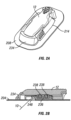
- one the plurality of display devices is a small (e.g., key fob) display device 14 ( FIG. 1 ) that is configured to display at least some of the sensor information, such as an analyte concentration value and a trend arrow.
- a key fob device is a small hardware device with a built-in authentication mechanism sized to fit on a key chain.
- any small display device 14 can be configured with the functionality as described herein with reference to the key fob device 14, including a wrist band, a hang tag, a belt, a necklace, a pendent, a piece of jewelry, an adhesive patch, a pager, an identification (ID) card, and the like, all of which are included by the phrase "small display device” and/or "key fob device” herein.
- the key fob device 14 includes electronics configured to receive and display displayable sensor information (and optionally configured to query the sensor electronics module for the displayable sensor information).
- the electronics include a RAM and a program storage memory configured at least to display the sensor data received from the sensor electronics module.
- the key fob device 14 includes an alarm configured to warn a host of a triggered alert (e.g., audio, visual and/or vibratory).
- the key fob device 14 includes a user interface, such as an LCD 602 and one or more buttons 604 that allows a user to view data, such as a numeric value and/or an arrow, to toggle through one or more screens, to select or define one or more user parameters, to respond to (e.g., silence, snooze, turn off) an alert, and/or the like.
- a user interface such as an LCD 602 and one or more buttons 604 that allows a user to view data, such as a numeric value and/or an arrow, to toggle through one or more screens, to select or define one or more user parameters, to respond to (e.g., silence, snooze, turn off) an alert, and/or the like.
- the key fob display device has a memory (e.g., such as in a gig stick or thumb drive) that stores sensor, drug (e.g., insulin) and other medical information, enabling a memory stick-type function that allows data transfer from the sensor electronics module to another device (e.g., a PC) and/or as a data back-up location for the sensor electronics module memory (e.g., data storage memory).
- the key fob display device is configured to be automatically readable by a network system upon entry into a hospital or other medical complex.
- the key fob display device includes a physical connector, such as USB port 606, to enable connection to a port (e.g., USB) on a computer, enabling the key fob to function as a data download device (e.g., from the sensor electronics module to a PC), a telemetry connector (e.g., Bluetooth adapter/connector for a PC), and/or enables configurable settings on the key fob device (e.g., via software on the PC that allows configurable parameters such as numbers, arrows, trend, alarms, font, etc.)
- user parameters associated with the small (key fob) display device can be programmed into (and/or modified) by a display device such as a personal computer, personal digital assistant, or the like.
- user parameters include contact information, alert/alarms settings (e.g., thresholds, sounds, volume, and/or the like), calibration information, font size, display preferences, defaults (e.g., screens), and/or the like.
- the small (key fob) display device can be configured for direct programming of user parameters.
- the small (key fob) display device comprises a telemetry module, such as Bluetooth, and a USB connector (or the like), such that the small (key fob) display device additionally functions as telemetry adapter (e.g., Bluetooth adapter) enabling direct wireless communication between the sensor electronics module and the PC, for example, wherein the PC does not include the appropriate telemetry adapter therein.
- telemetry adapter e.g., Bluetooth adapter
- one the plurality of display devices is a hand-held display device 16 ( FIG. 1 ) configured to display sensor information including an analyte concentration and a graphical representation of the analyte concentration over time.
- the hand-held display device comprises a display 608 sufficiently large to display a graphical representation 612 of the sensor data over a time period, such as a previous 1, 3, 5, 6, 9, 12, 18, or 24-hours of sensor data.
- the hand-held device 16 is configured to display a trend graph or other graphical representation, a numeric value, an arrow, and/or to alarm the host.
- FIG. 6 illustrates one embodiment of a hand-held display device
- the hand-held device can be any single application device or multi-application device, such as mobile phone, a palm-top computer, a PDA, portable media player (e.g., iPod, MP3 player), a blood glucose meter, an insulin pump, and/or the like.
- portable media player e.g., iPod, MP3 player
- a blood glucose meter e.g., an insulin pump, and/or the like.
- a mobile phone (or PDA) is configured to display (as described above) and/or relay sensor information, such as via a voice or text message to the host and/or the host's care provider.
- the mobile phone further comprises an alarm configured to warn a host of a triggered alert, such as in response to receiving a data package indicating triggering of the alert.
- the data package may include displayable sensor information, such as an on-screen message, text message, and/or pre-generated graphical representation of sensor data and/or transformed sensor data, as well as an indication of an alarm, such as an auditory alarm or a vibratory alarm, that should be activated by the mobile phone.
- one of the display devices is a drug delivery device, such as an insulin pump and/or insulin pen, configured to display sensor information.
- the sensor electronics module is configured to wirelessly communicate sensor diagnostic information to the drug delivery device in order to enable to the drug delivery device to consider (include in its calculations/algorithms) a quality, reliability and/or accuracy of sensor information for closed loop and/or semi-closed loop systems, which are described in more detail in U.S. Patent Publication No. 2005/0192557 , which is incorporated herein by reference in its entirety.
- the sensor electronic module is configured to wirelessly communicate with a drug delivery device that does not include a display, for example, in order to enable a closed loop and/or semi-closed loop system as described above.
- one of the display devices is a drug delivery device is a reference analyte monitor, such as a blood glucose meter, configured to measure a reference analyte value associated with an analyte concentration in a biological sample from the host.
- a reference analyte monitor such as a blood glucose meter
- one of the display devices is personal computer (PC) 20 ( FIG. 1 ) configured to display sensor information.
- the PC 24 has software installed, wherein the software enables display and/or performs data analysis (retrospective processing) of the historic sensor information.
- a hardware device can be provided (not shown), wherein the hardware device (e.g., dongle/adapter) is configured to plug into a port on the PC to enable wireless communication between the sensor electronics module and the PC.
- the PC 24 is configured to set and/or modify configurable parameters of the sensor electronics module 12 and/or small (key fob device) 14, as described in more detail elsewhere herein.
- one of the display devices is an on-skin display device that is splittable from, releasably attached to, and/or dockable to the sensor housing (mounting unit, sensor pod, or the like).
- release of the on-skin display turns the sensor off; in other embodiments, the sensor housing comprises sufficient sensor electronics to maintain sensor operation even when the on-skin display is released from the sensor housing.
- one of the display devices is a secondary device, such as a heart rate monitor, a pedometer, a temperature sensor, a car initialization device (e.g., configured to allow or disallow the car to start and/or drive in response to at least some of the sensor information wirelessly communicated from the sensor electronics module (e.g., glucose value above a predetermined threshold)).
- a car initialization device e.g., configured to allow or disallow the car to start and/or drive in response to at least some of the sensor information wirelessly communicated from the sensor electronics module (e.g., glucose value above a predetermined threshold)
- one of the display devices is designed for an alternative function device (e.g., a caller id device), wherein the system is configured to communicate with and/or translate displayable sensor information to a custom protocol of the alternative device such that displayable sensor information can be displayed on the alternative function device (display of caller id device).
- FIG. 1 is a diagram illustrating one embodiment of a continuous analyte sensor system 8 including a sensor electronics module 12.
- the system includes a continuous analyte sensor 10 physically connected to a sensor electronics module 12, which is in direct wireless communication with a plurality of different display devices 14, 16, 18, and/or 20.
- the sensor electronics module 12 includes electronic circuitry associated with measuring and processing the continuous analyte sensor data, including prospective algorithms associated with processing and calibration of the sensor data.
- the sensor electronics module 12 may be physically connected to the continuous analyte sensor 10 and can be integral with (non-releasably attached to) or releasably attachable to the continuous analyte sensor 10.
- the sensor electronics module 12 may include hardware, firmware, and/or software that enables measurement of levels of the analyte via a glucose sensor, such as an analyte sensor.
- the sensor electronics module 12 can include a potentiostat, a power source for providing power to the sensor, other components useful for signal processing and data storage, and a telemetry module for transmitting data from the sensor electronics module to one or more display devices.
- Electronics can be affixed to a printed circuit board (PCB), or the like, and can take a variety of forms.
- the electronics can take the form of an integrated circuit (IC), such as an Application-Specific Integrated Circuit (ASIC), a microcontroller, and/or a processor.
- the sensor electronics module 12 includes sensor electronics that are configured to process sensor information, such as sensor data, and generate transformed sensor data and displayable sensor information.
- a plurality of display devices are configured for displaying (and/or alarming) the displayable sensor information that has been transmitted by the sensor electronics module 12 (e.g., in a customized data package that is transmitted to the display devices based on their respective preferences).
- the display devices are configured to display the displayable sensor information as it is communicated from the sensor electronics module (e.g., in a data package that is transmitted to respective display devices), without any additional prospective processing required for calibration and real-time display of the sensor data.
- the plurality of display devices includes a small (key fob) display device 14, such as a wrist watch, a belt, a necklace, a pendent, a piece of jewelry, an adhesive patch, a pager, a key fob, a plastic card (e.g., credit card), an identification (ID) card, and/or the like, wherein the small display device comprises a relatively small display (e.g., smaller than the large display device) and is configured to display certain types of displayable sensor information (e.g., a numerical value and an arrow, in some embodiments).
- a small display device such as a wrist watch, a belt, a necklace, a pendent, a piece of jewelry, an adhesive patch, a pager, a key fob, a plastic card (e.g., credit card), an identification (ID) card, and/or the like
- the small display device comprises a relatively small display (e.g., smaller than the large display device) and is configured to display certain types of displayable sensor information
- one of the plurality of display devices is a large (hand-held) display device 16, such as a hand-held receiver device, a palm-top computer and/or the like, wherein the large display device comprises a relatively larger display (e.g., larger than the small display device) and is configured to display a graphical representation of the continuous sensor data (e.g., including current and historic data).
- Other display devices can include other hand-held devices, such as a cell phone or PDA 18, an insulin delivery device, a blood glucose meter, and/or a desktop or laptop computer 24.
- a plurality of different display devices are in direct wireless communication with the sensor electronics module (e.g., such as an on-skin sensor electronics module 12 that is physically connected to the continuous analyte sensor10) during a sensor session to enable a plurality of different types and/or levels of display and/or functionality associated with the displayable sensor information, which is described in more detail elsewhere herein.
- the sensor electronics module e.g., such as an on-skin sensor electronics module 12 that is physically connected to the continuous analyte sensor
- a glucose sensor comprises a continuous sensor, for example a subcutaneous, transdermal (e.g., transcutaneous), or intravascular device.
- the device can analyze a plurality of intermittent blood samples.
- the glucose sensor can use any method of glucose-measurement, including enzymatic, chemical, physical, electrochemical, spectrophotometric, polarimetric, calorimetric, iontophoretic, radiometric, immunochemical, and the like.
- a glucose sensor can use any known method, including invasive, minimally invasive, and non-invasive sensing techniques (e.g., fluorescent monitoring), to provide a data stream indicative of the concentration of glucose in a host.
- the data stream is typically a raw data signal, which is converted into a calibrated and/or filtered data stream that is used to provide a useful value of glucose to a user, such as a patient or a caretaker (e.g., a parent, a relative, a guardian, a teacher, a doctor, a nurse, or any other individual that has an interest in the wellbeing of the host).
- a caretaker e.g., a parent, a relative, a guardian, a teacher, a doctor, a nurse, or any other individual that has an interest in the wellbeing of the host.
- a glucose sensor can be any device capable of measuring the concentration of glucose.
- One exemplary embodiment is described below, which utilizes an implantable glucose sensor. However, it should be understood that the devices and methods described herein can be applied to any device capable of detecting a concentration of glucose and providing an output signal that represents the concentration of glucose.
- the analyte sensor is an implantable glucose sensor, such as described with reference to U.S. Patent 6,001,067 and U.S. Patent Publication No. US-2005-0027463-A1 .
- the analyte sensor is a transcutaneous glucose sensor, such as described with reference to U.S. Patent Publication No. US-2006-0020187-A1 .
- the sensor is configured to be implanted in a host vessel or extracorporeally, such as is described in U.S. Patent Publication No. US-2007-0027385-A1 , co-pending U.S. Patent Publication No. US-2008-0119703-A1 filed October 4, 2006 , co-pending U.S.
- the continuous glucose sensor comprises a transcutaneous sensor such as described in U.S. Patent 6,565,509 to Say et al. , for example.
- the continuous glucose sensor comprises a subcutaneous sensor such as described with reference to U.S. Patent 6,579,690 to Bonnecaze et al. or U.S. Patent 6,484,046 to Say et al. , for example.
- the continuous glucose sensor comprises a refillable subcutaneous sensor such as described with reference to U.S.
- the continuous glucose sensor comprises an intravascular sensor such as described with reference to U.S. Patent 6,477,395 to Schulman et al. , for example.
- the continuous glucose sensor comprises an intravascular sensor such as described with reference to U.S. Patent 6,424,847 to Mastrototaro et al. , for example.
- Figs. 2A and 2B are perspective and side views of a sensor system including a mounting unit 214 and sensor electronics module 12 attached thereto in one embodiment, shown in its functional position, including a mounting unit and a sensor electronics module matingly engaged therein.
- the mounting unit 214 also referred to as a housing or sensor pod, comprises a base 234 adapted for fastening to a host's skin.
- the base can be formed from a variety of hard or soft materials, and can comprises a low profile for minimizing protrusion of the device from the host during use.
- the base 234 is formed at least partially from a flexible material, which is believed to provide numerous advantages over conventional transcutaneous sensors, which, unfortunately, can suffer from motion-related artifacts associated with the host's movement when the host is using the device.
- the mounting unit 214 and/or sensor electronics module 12 can be located over the sensor insertion site to protect the site and/or provide a minimal footprint (utilization of surface area of the host's skin).
- a detachable connection between the mounting unit 214 and sensor electronics module 12 is provided, which enables improved manufacturability, namely, the relatively inexpensive mounting unit 214 can be disposed of when replacing the sensor system after its usable life, while the relatively more expensive sensor electronics module 12 can be reusable with multiple sensor systems.
- the sensor electronics module 12 is configured with signal processing (programming), for example, configured to filter, calibrate and/or other algorithms useful for calibration and/or display of sensor information.
- signal processing for example, configured to filter, calibrate and/or other algorithms useful for calibration and/or display of sensor information.
- an integral (non-detachable) sensor electronics module can be configured.
- the contacts 238 are mounted on or in a subassembly hereinafter referred to as a contact subassembly 236 configured to fit within the base 234 of the mounting unit 214 and a hinge 248 that allows the contact subassembly 236 to pivot between a first position (for insertion) and a second position (for use) relative to the mounting unit 214.
- a contact subassembly 236 configured to fit within the base 234 of the mounting unit 214 and a hinge 248 that allows the contact subassembly 236 to pivot between a first position (for insertion) and a second position (for use) relative to the mounting unit 214.
- hinge is a broad term and is used in its ordinary sense, including, without limitation, to refer to any of a variety of pivoting, articulating, and/or hinging mechanisms, such as an adhesive hinge, a sliding joint, and the like; the term hinge does not necessarily imply a fulcrum or fixed point about which the articulation occurs.
- the contacts 238 are formed from a conductive elastomeric material, such as a carbon black elastomer, through which the sensor 10 extends.
- Wireless communication protocols may be used to transmit and receive data between the sensor system 8 and the display device 14, 16, 18, 20.
- the wireless protocol used may be designed for use in a wireless sensor network that is optimized for periodic and small data transmissions (that may be transmitted at low rates if necessary) to and from multiple devices in a close range (e.g., a personal area network (PAN)).
- PAN personal area network
- the protocol may be optimized for periodic data transfers where transceivers may be configured to transmit data for short intervals and then enter low power modes for long intervals.
- the protocol may have low overhead requirements both for normal data transmissions and for initially setting up communication channels (e.g., by reducing header overhead) to reduce power consumption.
- burst broadcasting schemes e.g., one way communication
- This may eliminate overhead required for acknowledgement signals and allow for periodic transmissions that consume little power.
- FIG. 4B is a timing diagram of an exemplary sequence for establishing a communication channel between an analyte sensor system 8 and a display device 14, 16, 18, 20.
- the display device 14, 16, 18, 20 may initially "wake up" its transceiver 316 and wait to receive a beacon from the analyte sensor system 8.
- the analyte sensor system 8 may take one, two, or more beacons for the display device 14, 16, 18, 20 to receive the beacon and respond with a request.
- data may thereafter be sent and/or received as shown by the shaded time slots.
- the channel can then be closed once analyte sensor system 8 and display device 14, 16, 18, 20 determine that all requested data has been transmitted to the respective devices or it the transmission window time expires.
- the process is repeated.
- Continuously re-establishing a new communication channel to allow for partially or wholly powering down the transceiver 316 during each update interval T update can provide significant power savings and can allow the sensor electronics module 12 to operate continuously for six months or more without requiring a battery replacement.
- communication channels may be established so that only the desired display devices 14, 16, 18, 20 may receive the glucose information. This may prevent unauthorized use and interception of glucose measurement values.
- requests for specific glucose measurement values or communication of calibration or configuration information may be transmitted on an as-needed/requested basis between the sensor system 8 and display device 14, 16, 18, 20.
- the sensor electronics module 12 can be switched (manually or automatically) from a first state to a second state to facilitate pairing, wherein the window frequency F window is greater in the second state than in the first state. After paring, the sensor electronics module 12 can then switch back to the first state or switch to a third state that has a window frequency that is different from the first state and the second state. The sensor electronics module can switch back to the first state or to the third state automatically in response to the sensor electronics module determining a successful pairing between the two devices, or switched back to the first state or to the third state manually by a user via an external switch or user input using an electronics user interface.
- the first state corresponds to a storage mode in which window frequency F window is 0 (i.e.
- window frequency F window during the second state can be 30 seconds and the window frequency F window during the third state can be 5 minutes.
- the sensor electronics module 12 can be a separate unit that is configured to be connected to a continuous analyte sensor 10 as discussed above and illustrated in FIGS. 2A and 2B , for example.
- the sensor electronics module 12 can be manufactured and then stored in a container, such as a box, prior to use. To conserve power, the sensor electronics module 12 can be placed in a low power state while in the container and thereafter switched to pairing state after removal of the sensor electronics unit from the storage container.
- the sensor electronics module 12 can be kept in the low power state through use of an external magnet and a reed switch or hall-effect switch within the sensor electronics module.
- an external magnet to keep a sensor electronics module in a low power mode is described in more detail in U.S. Patent Application No. 13/247,856 filed on September 28, 2011 , the content of which are hereby incorporated by reference in its entirety.
- a magnet can be placed next to the sensor electronics module 12 during manufacturing next to the sensor electronics module 12 in the container to keep the sensor electronics module in the low power state while in the container.
- the sensor electronics module 12 can be removed from the container and the magnet removed from the proximity of the sensor electronics module to cause the sensor electronics module to switch to the pairing state.
- a reed switch, hall-effect switch or the like can reside in the sensor electronics module to trigger the switching of the sensor electronics module from the low power state to the pairing state, for example.
- the sensor electronics module 12 can be in the low power state while in storage, switched to the pairing state when removed from storage (e.g. by removing a magnet) and then switched to a normal operational state once the sensor electronics module 12 is paired with a display device.
- the low power state can include keeping the transceiver powered off or otherwise in a low power state wherein no beacons are transmitted.
- the pairing state can include a high window frequency F window , such as every 30 seconds, wherein one or more beacons are transmitted during each window.
- the normal operational state can include a relatively low window frequency F window , such as every 5 minutes, for opening a communication channel with one or more display devices to exchange information, including sensor data values.
- the sensor electronics module will automatically change from the high window frequency F window used to facilitate paring (e.g., the second state) to the normal operational window frequency F window (e.g., the third state) after a predetermined amount of time, such as 1 hour, should a successful pairing not occur within that time. This way, valuable battery power is not wasted by having a high window frequency F window for an extended period of time.
- the display device 14, 16, 18, 20 is configured through software instructions executed by a processor of the display device to vary windows for listening for a beacon from sensor electronics module 12. Doing so can conserve battery power as opposed to constantly having the display device listen for a beacon from the sensor electronics module.
- a state based approach for RF windowing can be used.
- the following is an example of states and substates that can be used in an implementation, but it is understood that more or fewer of these states and substates can be used depending upon the particular needs of a user. Further, it should be understood that, while this example provides times for the windowing, other times can be used depending upon the particular needs of a user and device properties.
- This example also contemplates implementations wherein the display device has a software application stored on the display device (which may be referred to herein as an "app") that is configured to cause the display device to request data from the sensor electronics module.
- the application may run as a background process on the display device and, while it is run in the background, the display device does not listen for beacons. States and substates in this example are the following:
- pairing of two devices may be required to establish a relationship between two devices that want to communicate with one another. Pairing may be accomplished during the channel establishment process described above between the two devices. Establishing a channel may involve broadcasting a unique ID by one device and a search and acquisition of this ID by another device.
- a parameter that may be used in device pairing is the master device ID.
- a master transmitter may broadcast its device ID (along with some other information) in the above described beacon and the receiver checks for the presence of the device ID of the transmitter with which it wants to communicate in the received beacons.
- the device ID may be a 2-byte value representing a specific master device, for example.
- a master device ID may provide some level of security, in that a slave device can be programmed to communicate only with a master device having a particular device ID number, additional security can be useful in some embodiments.
- a communication channel may be re-established during each update interval T update . As such, as part of the channel establishment process, regular and repeated re-authentication may also be provided.
- some embodiments of the present invention can use two pieces of information to pair a receiver with a particular transceiver device. These two pieces of information include the device ID described above and another value which is referred to herein as a sensor security code.
- the device ID is used as described above to filter receipt of non-matching messages at the lowest layer of the protocol stack.
- the sensor security code is used for a key based authentication scheme at the software application layer of the system.
- both the device ID and the sensor security code can be derived from an identifier (e.g., a manufacturer's serial number) associated with the sensor system 8 per the description below.
- the sensor system 8 comprises two fundamental components, the continuous sensor 10 and the electronics module 12. These two components may be separable from one another, allowing, for example, replacement of the continuous sensor portion 10.
- the identifier may be etched into, printed on or otherwise attached to a housing of the electronics module portion 12.
- the sensor system 8 may include seven alphanumeric characters printed on a housing of the sensor system 8, which can comprise the identifier used for identification purposes. This alphanumeric series of characters may be used to generate both the device ID used in the master beacons to establish a channel and to generate the sensor security code used for additional security in the glucose monitoring system. To maintain good data security, the alphanumeric characters and the sensor security code need not be transmitted over a wireless communication channel at any time.
- the seven alphanumeric characters are converted to seven 5 bit binary values as shown for example in Figure 6A . These 35 bits are then concatenated together and divided into a device ID and sensor security code as shown for example in Figure 4B . The most significant 11 bits, used for the device ID, are left-shifted by one bit and a one is inserted on the right, to produce a 12 bit value. Inserting the 1 on the right prevents the device number from being set to 0x0000. To produce a 16-bit device ID value, for example, four zeros can be used for the four most significant bits of the sequence. The remaining 24 bits of the original 35 concatenated bits can be used for the sensor security code.
- a given seven character alphanumeric ID, 'A65S34F' is converted to binary as follows using the binary mappings shown in FIG. 6A ,
- the device ID becomes 0000 0101 0001 1001 after a one is added as the least significant bit, and four zeros are added as the most significant bits.
- the other 24 bits are padded on the left with eight zeros to become the four byte value 0000 0000 0101 1101 0000 1100 1000 1111.
- the device ID becomes the two byte array [0x05][0x19] used as described above in the low level standardized communication protocol.
- the sensor security code becomes the four byte array [0x00][0x5D][0x0C][0x8F], used as described below.
- the identifier associated with the system is entered into the display device 14, 16, 18, 20.
- the sensor system 8 and the display device 14, 16, 18, 20 can each compute the same device ID and sensor security code using the algorithm described above.
- FIG. 7 is a flowchart illustrating one embodiment of an aspect of a process for pairing a transmitter with a receiver using a device ID and sensor security code.
- the transceiver in the sensor system 8 sends one or more message beacons that include the device ID and a challenge value used in conjunction with the sensor security code as will be described below.
- the display device 14, 16, 18, 20 may receive the transmission and determine whether to pair with the sensor system 8 by checking for a match between the device ID in the received beacon and the device ID it is searching for. If the device ID does not match, the pairing process can end, as shown in block 714. If the device ID does match, a communication channel is established.
- the part of the communication process involved in establishing a communication channel may be handled by the transceiver circuitry 316, 338 in accordance with the protocols established for the standardized communication and embedded in the transceiver circuitry.
- the processor 330 need not manage or even be aware of received beacons that do not contain the appropriate device ID.
- FIG. 8 is flowchart of an exemplary method for establishing an authenticated communication channel between an analyte sensor system 8 and a primary device 16 or a secondary display device 14, 18.
- the analyte sensor system 8 transmits a beacon containing a challenge value generated, for example as described above in FIG. 7 .
- This beacon may be received at a primary display device 16 and/or secondary display device 14, 18 as shown in blocks 804a and 804b.
- the hash algorithm may further generate the primary hash value based on other information and identifiers such as an identifier associated with the primary display device to more easily allow an analyte sensor system 8 to determine a display type or the various or limited capabilities of the primary display 16.
- the analyte sensor system 8 may have a list of allowable display identifiers or codes stored in memory.
- a key value may be specific to a primary display device 16 type.
- the key value may be a configuration key that is provided in the primary display device 16 by the manufacturer to permit the primary display device 16 to be used to control and configure the analyte sensor system 8. That is, the use of the configuration key may identify the display device 16 as a primary display device to the analyte sensor system 8, thereby determining the type of data exchanged and functionality allowed between the analyte sensor system 8 and the primary display device 16.
- the secondary display device 14, 18 may also generate a secondary hash value in block 806b.
- the secondary hash value may be generated using a hash algorithm based on an analyte sensor system 8 identifier, a key value specific to the secondary display device 14, 18 type, and the challenge value.
- the key value may be a "permission" key that is different than the configuration key associated with a primary device and may be provided in the secondary display device 14, 18 by the manufacturer or a software supplier of software implemented on the secondary display device.
- the permission key may identify the display device 14, 16, 18, 20 as a secondary display device 14, 18 and indicate to the sensor system 8 that the secondary display device 14, 18 has permission to display glucose data to a user.
- the primary and secondary display devices 14, 16, 18, 20 may send the hash values to the analyte sensor system 8.
- the analyte sensor system 8 may also generate its own hash values for each type of display that the analyte sensor system 8 is expecting to receive a request from (referred to herein from time to time as "expected hash values").
- the analyte sensor system 8 may generate an expected hash value for a primary display device 16 and an expected hash value for a secondary display device 14, 18.
- the expected hash values may be compared to the hash value(s) received from the primary or secondary display device(s), as shown in blocks 810a and 810b.
- a received hash value matches none of the expected hash values, then the method ends in block 814 and no data is sent by the analyte sensor system 8 as the authentication failed. If the received hash value matches one of the expected hash values, then the communication request from the display device can be considered authenticated and a communication channel opened between the sensor system 8 and display device and data may be sent between the analyte sensor system 8 the primary display device 16 or secondary display device 14, 18 as shown in blocks 812a and 812b, respectively.
- the type of data exchanged between the analyte sensor system 8 and the display device 14, 16, 18, 20 may depend on the type of display device (e.g., primary or secondary).
- the analyte sensor system 8 can be permitted to request calibration information (e.g., external calibration reference values) from a primary display device 16 but not from a secondary display device 14, 18.
- calibration information e.g., external calibration reference values
- the analyte sensor system 8 may refuse or ignore the data.
- the sensor system 8 can include multiple keys stored therein; for example, one key for each type of approved device.
- the key priority list can be adaptive. For example, the key that was used to generate a matching hash value can made the top priority key. That way, during the next authentication process, the key is the first key used to generate the sensor system has value in step 808 of FIG. 8 , for example, and if there is a match, then no further hash values need be generated.
- the analyte sensor system 8 may reserve just a fraction (represented by a data transmission window interval T window ) of the update interval T update for exchanging data with display devices 14, 16, 18, 20.
- a data transmission window interval T window an analyte sensor system 8 may be able to communicate with multiple display devices 14, 16, 18, 20.
- communicating with multiple display devices 14, 16, 18, 20 may consume significant amounts of power.
- Some embodiments may limit the amount of display devices 14, 16, 18, 20 that may communicate with the analyte sensor system 8 during an interval T window.
- the length of the data transmission window interval T window may be limited by the analyte sensor system 8.
- the analyte sensor system 8 may refuse requests from display devices 14, 16, 18, 20 once the analyte sensor system 8 has already communicated with a predetermined threshold number of display devices (e.g., three display devices during a transmission window T window ).
- FIG. 9 is a timing diagram showing an exemplary scheme for exchanging data between an analyte sensor system 8 and a plurality of display devices 14, 16, 18.
- the analyte sensor system 8 may be configured to send and receive data during specified time slots.
- T update (which may be at the beginning or end of the interval, for example)
- an analyte sensor system 8 may begin transmitting beacons as described above.
- a primary display device 16 may successfully receive the beacon (e.g., after the analyte sensor system 8 sends out two beacons as illustrated in FIG. 9 ) and send a data exchange request to the analyte sensor system 8 within the third time slot of the primary device's timing diagram.
- data may be exchanged between the two devices as indicated by the shaded time slots.
- the data in the first data time slot may include the most recent glucose measurement values and data in subsequent time slots may include calibration data or other control or configuration data.
- the analyte sensor system 8 may resume sending beacons. As shown in FIG. 9 , a first secondary display device 14 may be attempting to communicate with the analyte sensor system 8 and begin looking for the beacon at the beginning of T window . In this case, while the first secondary display device 14 may receive the beacon at the same time as the primary display device 16, the analyte sensor system 8 may ignore subsequent requests from the first secondary display device 14 if it is already communicating with a primary display device 16. As will be further described below, in some embodiments, the type of display device may not be a factor in determining who first establishes the communication channel.
- the display device that responds to the beacon first will be able to establish the communication channel and other devices may have to wait.
- the first secondary display device 14 responds to the beacon before the primary display device 16, then a channel would be established initially with the first secondary display device 14. If the primary display device 16 responds first, the first secondary display device 14 may continue to listen for a beacon from the analyte sensor system 8 until it is authenticated by the analyte sensor system 8 and a channel is established between the analyte sensor system 8 and the first secondary display device 14. As shown in FIG.
- the first secondary display device 14 may receive a beacon and establish a channel after the analyte sensor system 8 has finished communicating with the primary display device 16. The first secondary display device 14 may then exchange data with the analyte sensor system 8 for one or more time slots and subsequently close the channel.
- the analyte sensor system 8 may resume sending beacons.
- a second secondary display device 18 may additionally be attempting to communicate with the analyte sensor system 8 and begin searching to acquire a beacon during T window .
- the second secondary display device 18 may continuously look for the beacon until the analyte sensor system 8 finally acknowledges and authenticates the second secondary display devices 18 after communicating with the primary display device 16 and the first secondary display device 14.
- the second secondary display device 18 may exchange data with the analyte sensor system 8 and close the channel. This process may continue with other display devices 20 until a specified communication interval T window ends and the analyte sensor system 8 stops sending beacons until the beginning of another transmission window (e.g. at the beginning of the next update time interval T update ).
- the number of display devices to which the analyte sensor system 8 communicates may be limited in several ways.
- the analyte sensor system 8 may stop transmitting beacons or responding to data exchange requests after exchanging data with a predetermined number of display devices 14, 16, 18, 20.
- the analyte sensor system 8 may only be allowed to communicate with a maximum of three devices during each data transmission window interval T window .
- the maximum number of display devices that can communicate during a transmission window interval can be variable.
- the variable can be set during manufacturing of sensor electronics module 12, can be user configurable by using display device 14, 16, 18, 20, for example, or can be automatically adjusted by sensor system 8 or display device 14, 16, 18, 20 based on one or more criteria.
- the criteria can include a monitored battery level of the analyte sensor system 8. For example, if the battery level is below a threshold, the analyte sensor system 8 may be configured to only communicate with one display device 14, 16, 18, 20.
- the criteria can include: (i) one or more errors detected by sensor system 8 or display device 14, 16, 18, 20, (ii) a currently measured, previously measured and/or predicted glucose concentrations meeting or exceeding a predetermined threshold, (iii) a glucose concentration trend of the host based on currently measured, previously measured and/or predicted glucose concentrations, (iv) a rate of change of glucose concentration of the host based currently measured, previously measured and/or predicted glucose concentrations meeting or exceeding a predetermined threshold, (v) whether the host is determined to be in or near hyperglycemia based on currently measured, previously measured and/or predicted glucose concentrations, (vi) whether the host is determined to be in or near hypoglycemia based on currently measured, previously measured and/or predicted glucose concentrations, (vii) user inputted activity of the host (e.g., exercising or sleeping), (viii) time since a sensor session has started (e.g., when a new sensor 10 is used), and (ix) type of display device.
- limiting communication based on the battery level may be done by shortening the transmission window T window , restricting the types of devices that may communicate with the sensor system, limit the types of data that can be exchanged between the sensor system and display devices 14, 16, 18, 20, or the like.
- FIG. 9 shows first communicating with a primary display device 16 and then two secondary display devices 14, 18, it should be appreciated that the order and type of display devices may not matter.
- the analyte sensor system 8 may communicate first with a secondary display device 14 and then with a primary display device 16.
- the analyte sensor system 8 may communicate only with a primary display device 16 during the communication interval T primary .
- the analyte sensor system 8 may communicate with only secondary display devices 14, 18 during the communication interval T secondary .
- the analyte sensor system 8 may implement a priority scheme to ensure the analyte sensor system 8 communicates with a primary display device 16 during the transmission window.
- the analyte sensor system 8 may establish a specified time interval (T primary ) reserved for communication with a primary display device 16 within the transmission window interval T window .
- T primary which may be at the beginning of the transmission window T window
- the analyte sensor system 8 may be configured to only respond to and authenticate with a primary display device 16 and ignore other requests.
- secondary display devices 14, 18 may have the opportunity to establish a channel in addition to the primary display device.
- the primary display device 16 may incorporate functionality such as special alerts or alarms that help to ensure that a user maintains safe glucose levels. Regulations or safety guidelines may therefore require that the primary display device 16 always be used.
- the analyte sensor system 8 may only allow communication with a secondary display device 14, 18 if the analyte sensor system 8 has already sent glucose information to a primary display device 16 in a given transmission window T window .
- a new sensor session may be established.
- communication of glucose values to secondary devices 14, 18 may be disallowed until initiating of the sensor session is performed between a primary display device 16 and sensor system 8.
- the initiation process may include providing calibration data and setting alert thresholds for the sensor session.
- secondary display devices 14, 18 may be allowed to exchange data with the sensor system 8, such as receive glucose measurements and perform various functions (e.g., display estimated glucose values (EGVs), trend graphs, arrows, sound alarms) even if the primary display device 16 is not currently in proximity to or exchanging data with the analyte sensor system 8.
- EUVs display estimated glucose values
- trend graphs trend graphs
- arrows sound alarms
- the secondary display device 14, 18 may be restricted. As such, communication between the secondary display device 14, 18 and the analyte sensor system 8 may be based on communication between the primary display device 16 and the analyte sensor system 8.
- the analyte sensor system 8 may not actively measure glucose concentration values until the sensor session is initiated with a primary display device 16. In this case, the analyte sensor system 8 may not transmit any information and a secondary display 14, 18 would not be able receive any information or establish a channel. In this case, a secondary display device 14, 18 would not be able to communicate until the sensor session was initiated by a primary display device 16.
- FIG. 10 is a flowchart of an exemplary method for communication between an analyte sensor system 8 and a secondary display device 14, 18.
- an analyte sensor system 8 may receive a request for sensor data from a secondary display device 14, 18 during a transmission window.
- the analyte sensor system 8 may determine whether a communication channel been established between the analyte sensor system 8 and a primary display device 16 during the transmission window. If no communication channel was established with a primary display device 16, then the method may end in block 1010 and the analyte sensor system 8 may refuse to communicate with the secondary display device 14, 18.
- the analyte sensor system 8 may authenticate and establish a communication channel with the secondary display device 14, 18 as shown in block 1006. In block 1008, the analyte sensor system 8 may then transmit sensor data to the secondary display device 14, 18.
- T window of an analyte sensor system 8 may only be a small fraction (e.g., 30 seconds) of a much longer update interval (e.g., five minutes), it may be desirable for a display device 14, 16, 18, 20 to have specific information about the time when T window opens to know when to listen for the beacon sent by the analyte sensor system 8.
- the secondary display device 14, 18 may then establish a communication channel with the analyte sensor system 8 based on the beacon information as shown in block 1108. Moreover, in some embodiments, an authentication procedure, similar to the authentication procedure described above, may be used between the primary display device 16 and the secondary display device 14, 18 to establish communication in block 1104.
- FIG. 12A is a timing diagram of an exemplary timing scheme for transmitting data and obtaining and processing analyte sensor measurements.
- each update interval T update may be divided into two periods: a sensor measurement and processing period 1220a, 1220b and a data communication period 1230a, 1230b. If the T update interval is five minutes, then a four minute and 30 second measurement cycle 1220a may be followed by a thirty second transmission window 1230a, for example.
- Measurement circuitry 310 may be powered down during the transmission window 1230a and the transceiver 316 may be powered down during a measurement cycle 1220a. This may be repeated for each update interval.
- FIG. 12B is a flowchart of an exemplary method for interleaving an analyte sensor measurement and processing period with a data communication period for transmitting glucose measurement values.
- the analyte sensor system 8 may activate sensor measurement circuitry 310 and deactivate the transceiver 316 during a first time interval.
- the analyte sensor system 8 may obtain and process sensor readings during the first time interval.
- the analyte sensor system 8 may deactivate the sensor measurement circuitry 310 and activate the transceiver 316 during a second time interval corresponding to a data transmission window.
- the analyte sensor system 8 may then transmit sensor data during the second time interval to a display device 14, 16, 18, 20. This process may be continuously repeated for each update interval.
- the measurement circuitry 310 may further be deactivated for the portion of the time interval that it is not being used. Accordingly, the activating and deactivating in FIG. 12 B may include selectively powering down/up some or all of the sensor measurement circuitry 310 and transceiver 316, or selectively placing the sensor measurement circuitry 310 and transceiver 316 into a low power mode such as a sleep mode.
- an entire data set 1310a (e.g., a data file) may be transmitted as opposed to just the requested range of glucose measurement related data.
- the transmitted data set 1310 may include a range of glucose measurement related data that exceeds the requested range. This may reduce processing time and power needed to retrieve and send only the specifically requested range of glucose measurement related data. This may provide for significant power savings which may allow the battery of sensor system 8 to last longer.
- a user of the sensor system 8 may recognize a problem or otherwise determine a need to contact technical support to resolve the problem or need. At that time, the technical support may want the user to obtain some or all of the technical support log file from the sensor system 8. However, since the sensor system 8 may not have a display and a display device may only be able to communicate with the sensor system infrequently (only when the next transmission window opens), the user may have to wait a significant amount of time before being able to obtain the technical support log file from the sensor system and display information in the file on the display device or transmit (for example over the Internet) some or all of the technical file log from the display device to a computer associated with the technical support.
- the sensor system 8 can send a message to a display device anytime the sensor system determines that technical support information stored in the technical support log file is worth having on the display device.
- an occurrence can include: (i) the sensor system going out of calibration after a calibration; (ii) the sensor system not going out of calibration, but the difference between a reference value and a corresponding estimated glucose value exceeds a predetermined amount; (iii) the sensor system software or firmware encounters a particular type of error, even if the system determines that it has resolved the error; (iv) the sensor system firmware or software encounters an error that results in alerting the user to the error via the display device; and (v) periods of time during use of a sensor where the sensor system detects noise or other kinds of aberrations above a predetermined level.
- the display device When the display device receives the message, it can be programmed to automatically request some or all of the support file log.
- the display device may also automatically send the support log file to the technical support computer over a communication network (e.g., cellular network is the display device is a smart phone or over the Internet if the display device is a PC connected to the Internet). If a communication network is not immediately available, the display device can send the support log file technical support upon connecting to the display device to suitable communication network. This way, the display device and/or technical support may already have the technical information on hand when a user calls technical support to resolve a problem or need.
- a communication network e.g., cellular network is the display device is a smart phone or over the Internet if the display device is a PC connected to the Internet.
- the message sent by the sensor system is a bit in a data page sent from the sensor system indicative of the presence of the technical support information.
- the data page is the beacon data page in some implementations. Having the bit can provide the flexibility to obtain the technical support data without having to specify all the conditions under which the display device needs to obtain the technical support log file. For example, the display device can also choose not to obtain the technical support log file from the sensor system if similar conditions occurred in the recent past and technical support was already performed the previous time.
- US-2006-0036144-A1 U.S. Patent Publication No. US-2006-0016700-A1 ; U.S. Patent Publication No. US-2006-0142651-A1 ; U.S. Patent Publication No. US-2006-0086624-A1 ; U.S. Patent Publication No. US-2006-0068208-A1 ; U.S. Patent Publication No. US-2006-0040402-A1 ; U.S. Patent Publication No. US-2006-0036142-A1 ; U.S. Patent Publication No. US-2006-0036141-A1 ; U.S. Patent Publication No. US-2006-0036143-A1 ; U.S.
- Patent Publication No. US-2006-0036140-A1 U.S. Patent Publication No. US-2006-0036139-A1 ; U.S. Patent Publication No. US-2006-0142651-A1 ; U.S. Patent Publication No. US-2006-0036145-A1 ; U.S. Patent Publication No. US-2006-0036144-A1 ; U.S. Patent Publication No. US-2006-0200022-A1 ; U.S. Patent Publication No. US-2006-0198864-A1 ; U.S. Patent Publication No. US-2006-0200019-A1 ; U.S. Patent Publication No. US-2006-0189856-A1 ; U.S. Patent Publication No.
- the term 'including' should be read to mean ⁇ including, without limitation,' 'including but not limited to,' or the like;
- the term 'comprising' as used herein is synonymous with 'including,' 'containing,' or 'characterized by,' and is inclusive or open-ended and does not exclude additional, unrecited elements or method steps;
- the term 'having' should be interpreted as 'having at least;
- the term 'includes' should be interpreted as ⁇ includes but is not limited to;
- the term 'example' is used to provide exemplary instances of the item in discussion, not an exhaustive or limiting list thereof; adjectives such as 'known', 'normal', 'standard', and terms of similar meaning should not be construed as limiting the item described to a given time period or to an item available as of a given time, but instead should be read to encompass known, normal, or standard technologies that may be available or known now or at any time in the future; and use
- a group of items linked with the conjunction 'and' should not be read as requiring that each and every one of those items be present in the grouping, but rather should be read as 'and/or' unless expressly stated otherwise.
- a group of items linked with the conjunction 'or' should not be read as requiring mutual exclusivity among that group, but rather should be read as 'and/or' unless expressly stated otherwise.
Landscapes
- Engineering & Computer Science (AREA)
- Health & Medical Sciences (AREA)
- Life Sciences & Earth Sciences (AREA)
- Computer Networks & Wireless Communication (AREA)
- Biomedical Technology (AREA)
- Signal Processing (AREA)
- Medical Informatics (AREA)
- Public Health (AREA)
- General Health & Medical Sciences (AREA)
- Physics & Mathematics (AREA)
- Molecular Biology (AREA)
- Surgery (AREA)
- Veterinary Medicine (AREA)
- Animal Behavior & Ethology (AREA)
- Heart & Thoracic Surgery (AREA)
- Biophysics (AREA)
- Pathology (AREA)
- Business, Economics & Management (AREA)
- Primary Health Care (AREA)
- General Business, Economics & Management (AREA)
- Epidemiology (AREA)
- Emergency Medicine (AREA)
- Optics & Photonics (AREA)
- Computer Security & Cryptography (AREA)
- Physiology (AREA)
- Measurement Of The Respiration, Hearing Ability, Form, And Blood Characteristics Of Living Organisms (AREA)
- Investigating Or Analysing Biological Materials (AREA)
Applications Claiming Priority (6)
| Application Number | Priority Date | Filing Date | Title |
|---|---|---|---|
| US201161538447P | 2011-09-23 | 2011-09-23 | |
| EP19152995.7A EP3505065B1 (de) | 2011-09-23 | 2012-09-21 | Systeme und verfahren zur verarbeitung und übertragung von sensordaten |
| EP16177893.1A EP3092949B1 (de) | 2011-09-23 | 2012-09-21 | Systeme und verfahren zur verarbeitung und übertragung von sensordaten |
| EP21158122.8A EP3888551B1 (de) | 2011-09-23 | 2012-09-21 | Systeme und verfahren zur verarbeitung und übertragung von sensordaten |
| EP12833164.2A EP2757951B1 (de) | 2011-09-23 | 2012-09-21 | Systeme und verfahren zur verarbeitung und übertragung von sensordaten |
| PCT/US2012/056736 WO2013044153A1 (en) | 2011-09-23 | 2012-09-21 | Systems and methods for processing and transmitting sensor data |
Related Parent Applications (4)
| Application Number | Title | Priority Date | Filing Date |
|---|---|---|---|
| EP21158122.8A Division EP3888551B1 (de) | 2011-09-23 | 2012-09-21 | Systeme und verfahren zur verarbeitung und übertragung von sensordaten |
| EP12833164.2A Division EP2757951B1 (de) | 2011-09-23 | 2012-09-21 | Systeme und verfahren zur verarbeitung und übertragung von sensordaten |
| EP19152995.7A Division EP3505065B1 (de) | 2011-09-23 | 2012-09-21 | Systeme und verfahren zur verarbeitung und übertragung von sensordaten |
| EP16177893.1A Division EP3092949B1 (de) | 2011-09-23 | 2012-09-21 | Systeme und verfahren zur verarbeitung und übertragung von sensordaten |
Publications (2)
| Publication Number | Publication Date |
|---|---|
| EP4465307A2 true EP4465307A2 (de) | 2024-11-20 |
| EP4465307A3 EP4465307A3 (de) | 2025-02-19 |
Family
ID=47910685
Family Applications (6)
| Application Number | Title | Priority Date | Filing Date |
|---|---|---|---|
| EP24193530.3A Pending EP4465307A3 (de) | 2011-09-23 | 2012-09-21 | Systeme und verfahren zur verarbeitung und übertragung von sensordaten |
| EP16177893.1A Active EP3092949B1 (de) | 2011-09-23 | 2012-09-21 | Systeme und verfahren zur verarbeitung und übertragung von sensordaten |
| EP19152995.7A Active EP3505065B1 (de) | 2011-09-23 | 2012-09-21 | Systeme und verfahren zur verarbeitung und übertragung von sensordaten |
| EP12833164.2A Revoked EP2757951B1 (de) | 2011-09-23 | 2012-09-21 | Systeme und verfahren zur verarbeitung und übertragung von sensordaten |
| EP19152990.8A Active EP3505064B8 (de) | 2011-09-23 | 2012-09-21 | Systeme und verfahren zur verarbeitung und übertragung von sensordaten |
| EP21158122.8A Active EP3888551B1 (de) | 2011-09-23 | 2012-09-21 | Systeme und verfahren zur verarbeitung und übertragung von sensordaten |
Family Applications After (5)
| Application Number | Title | Priority Date | Filing Date |
|---|---|---|---|
| EP16177893.1A Active EP3092949B1 (de) | 2011-09-23 | 2012-09-21 | Systeme und verfahren zur verarbeitung und übertragung von sensordaten |
| EP19152995.7A Active EP3505065B1 (de) | 2011-09-23 | 2012-09-21 | Systeme und verfahren zur verarbeitung und übertragung von sensordaten |
| EP12833164.2A Revoked EP2757951B1 (de) | 2011-09-23 | 2012-09-21 | Systeme und verfahren zur verarbeitung und übertragung von sensordaten |
| EP19152990.8A Active EP3505064B8 (de) | 2011-09-23 | 2012-09-21 | Systeme und verfahren zur verarbeitung und übertragung von sensordaten |
| EP21158122.8A Active EP3888551B1 (de) | 2011-09-23 | 2012-09-21 | Systeme und verfahren zur verarbeitung und übertragung von sensordaten |
Country Status (4)
| Country | Link |
|---|---|
| US (10) | US9386522B2 (de) |
| EP (6) | EP4465307A3 (de) |
| CN (4) | CN111887862B (de) |
| WO (1) | WO2013044153A1 (de) |
Families Citing this family (135)
| Publication number | Priority date | Publication date | Assignee | Title |
|---|---|---|---|---|
| US8456301B2 (en) | 2007-05-08 | 2013-06-04 | Abbott Diabetes Care Inc. | Analyte monitoring system and methods |
| US8160900B2 (en) | 2007-06-29 | 2012-04-17 | Abbott Diabetes Care Inc. | Analyte monitoring and management device and method to analyze the frequency of user interaction with the device |
| CA2830283C (en) | 2011-03-25 | 2016-11-01 | Certicom Corp. | Interrogating an authentication device |
| EP2693945B1 (de) | 2011-04-08 | 2019-03-13 | Dexcom, Inc. | Systeme und verfahren zur verarbeitung und übertragung von sensordaten |
| EP4465307A3 (de) | 2011-09-23 | 2025-02-19 | Dexcom, Inc. | Systeme und verfahren zur verarbeitung und übertragung von sensordaten |
| US9396337B2 (en) * | 2012-04-11 | 2016-07-19 | Intermec Ip Corp. | Wireless sensor field enumeration |
| US9788765B2 (en) | 2012-09-28 | 2017-10-17 | Dexcom, Inc. | Zwitterion surface modifications for continuous sensors |
| US9787568B2 (en) * | 2012-11-05 | 2017-10-10 | Cercacor Laboratories, Inc. | Physiological test credit method |
| US9369290B2 (en) | 2012-11-30 | 2016-06-14 | Certicom Corp. | Challenge-response authentication using a masked response value |
| US9727720B2 (en) * | 2012-11-30 | 2017-08-08 | Certicom Corp. | Challenge-response authentication using a masked response value |
| US9355242B2 (en) * | 2012-12-17 | 2016-05-31 | Intel Corporation | Method and apparatus for managing and accessing personal data |
| US9589462B1 (en) * | 2012-12-20 | 2017-03-07 | Centrak, Inc. | System and method for CCX based sensor data tracking with highly assured data delivery |
| EP2763071A1 (de) * | 2013-01-31 | 2014-08-06 | Sensirion AG | Authentifizierung eines chemischen Sensors in einer tragbaren elektronischen Vorrichtung |
| WO2014122445A1 (en) * | 2013-02-08 | 2014-08-14 | Bae Systems Plc | A data processing method and apparatus |
| US9737250B2 (en) | 2013-03-15 | 2017-08-22 | Dexcom, Inc. | Membrane for continuous analyte sensors |
| JP6108892B2 (ja) * | 2013-03-18 | 2017-04-05 | キヤノン株式会社 | 電子機器および電源制御方法 |
| JP6568517B2 (ja) | 2013-04-30 | 2019-08-28 | アボット ダイアベティス ケア インコーポレイテッドAbbott Diabetes Care Inc. | ユーザの連続グルコースモニタリングのための装置、およびユーザの連続検体モニタリングのためのセンサ制御装置を準備する方法 |
| US10950340B2 (en) * | 2013-04-30 | 2021-03-16 | Essity Hygiene And Health Aktiebolag | Process and arrangement for collecting and storing data related to a condition of an absorbent product |
| RU2693019C2 (ru) * | 2013-05-15 | 2019-07-01 | Владимир КРАНЦ | Мобильный телефон с улучшенными функциями |
| US9172517B2 (en) * | 2013-06-04 | 2015-10-27 | Texas Instruments Incorporated | Network power optimization via white lists |
| EP3777656A1 (de) | 2013-06-06 | 2021-02-17 | Profusa, Inc. | Vorrichtung und verfahren zur detektion optischer signale aus implantierten sensoren |
| US9251455B2 (en) * | 2013-08-22 | 2016-02-02 | Verily Life Sciences Llc | Using unique identifiers to retrieve configuration data for tag devices |
| US9901250B2 (en) | 2013-10-09 | 2018-02-27 | Senseonics, Incorporated | Use of a sensor with multiple external sensor transceiver devices |
| US20150116127A1 (en) * | 2013-10-25 | 2015-04-30 | Simmonds Precision Products, Inc. | Energy-efficient wireless sensing for asynchronous event monitoring |
| US10729388B2 (en) | 2013-10-28 | 2020-08-04 | Dexcom, Inc. | Devices used in connection with continuous analyte monitoring that provide the user with one or more notifications, and related methods |
| WO2015062064A1 (zh) * | 2013-11-01 | 2015-05-07 | 华为终端有限公司 | 数据传输方法、终端及数据传输方法系统 |
| CN105706423A (zh) | 2013-11-07 | 2016-06-22 | 德克斯康公司 | 用于分析物值的发射和连续监测的系统和方法 |
| US10004435B2 (en) | 2013-11-14 | 2018-06-26 | Dexcom, Inc. | Devices and methods for continuous analyte monitoring |
| EP3780689A1 (de) * | 2013-12-27 | 2021-02-17 | Abbott Diabetes Care, Inc. | Systeme, vorrichtungen und verfahren zur authentifizierung in einer analytüberwachungsumgebung |
| EP4343784A3 (de) * | 2013-12-27 | 2024-06-12 | Abbott Diabetes Care Inc. | Anwendungsschnittstelle und anzeigesteuerung in einer analytüberwachungsumgebung |
| EP3091893B1 (de) * | 2014-01-10 | 2020-11-18 | Ascensia Diabetes Care Holdings AG | Konfigurationssynchronisationsvorrichtung und verfahren für medizinische endnutzervorrichtungen |
| US9459089B2 (en) * | 2014-04-09 | 2016-10-04 | Qualcomm Incorporated | Method, devices and systems for detecting an attachment of an electronic patch |
| EP3624475B1 (de) * | 2014-05-21 | 2024-03-20 | Abbott Diabetes Care, Inc. | Verwaltung von mehreren vorrichtungen innerhalb einer analytüberwachungsumgebung |
| CN105335112B (zh) * | 2014-05-30 | 2020-08-18 | 阿里巴巴集团控股有限公司 | 多屏显示的信息处理和主控端内容发送方法、装置 |
| US9642556B2 (en) * | 2014-06-27 | 2017-05-09 | Intel Corporation | Subcutaneously implantable sensor devices and associated systems and methods |
| JP6184907B2 (ja) * | 2014-06-30 | 2017-08-23 | 日本光電工業株式会社 | 口腔用測定装置、咬合評価システム、及びプログラム |
| EP3167586B1 (de) | 2014-07-07 | 2023-01-25 | Ascensia Diabetes Care Holdings AG | Verbessertes koppeln von geräten unter berücksichtigung mindest einer bedingung |
| US9635147B2 (en) * | 2014-07-09 | 2017-04-25 | The Regents Of The University Of Michigan | Protocol for an electronic device to receive a data packet from an external device |
| EP3185489B1 (de) * | 2014-08-19 | 2019-09-25 | Nec Corporation | Kommunikationsvorrichtung, kommunikationssystem und kommunikationsverfahren |
| CN111901799B (zh) * | 2014-08-29 | 2025-02-25 | 麦克赛尔株式会社 | 通信系统、通信装置和通信终端装置 |
| CA3211770A1 (en) | 2014-10-06 | 2016-04-14 | Dexcom, Inc. | System and method for data analytics and visualization |
| WO2016064893A1 (en) | 2014-10-20 | 2016-04-28 | Taser International, Inc. | Systems and methods for distributed control |
| MX2017007142A (es) * | 2014-12-05 | 2017-10-11 | Lifecycle Tech Pty Ltd | Metodo y sistema para mejorar una respuesta fisiologica. |
| WO2016118635A1 (en) * | 2015-01-21 | 2016-07-28 | Dexcom, Inc. | Continuous gilucose monitor communication with multiple display devices |
| JP6901395B2 (ja) | 2015-02-10 | 2021-07-14 | デックスコム・インコーポレーテッド | 連続的グルコースデータを配信するためのシステム及び方法 |
| US10251605B2 (en) | 2015-02-16 | 2019-04-09 | Verily Life Sciences Llc | Bandage type of continuous glucose monitoring system |
| JP6614782B2 (ja) | 2015-03-18 | 2019-12-04 | キヤノン株式会社 | 通信装置、制御方法、及びプログラム |
| US10079829B2 (en) * | 2015-04-02 | 2018-09-18 | The Boeing Company | Secure provisioning of devices for manufacturing and maintenance |
| US9700669B2 (en) * | 2015-04-16 | 2017-07-11 | Flowonix Medical Incorporated | Patient programmer for implantable drug delivery device |
| US10085640B2 (en) * | 2015-05-12 | 2018-10-02 | Dexcom, Inc. | Distributed system architecture for continuous glucose monitoring |
| US10292630B2 (en) * | 2015-06-01 | 2019-05-21 | Verily Life Sciences Llc | Optical sensor for bandage type monitoring device |
| US10765353B2 (en) * | 2015-07-02 | 2020-09-08 | Verily Life Sciences Llc | Calibration methods for a bandage-type analyte sensor |
| CN106394399A (zh) * | 2015-07-28 | 2017-02-15 | 比亚迪股份有限公司 | 车内健康体检系统及车内健康体检方法及汽车 |
| EP3357280B1 (de) * | 2015-09-29 | 2020-12-09 | Koninklijke Philips N.V. | Ferneinleitung von aufträgen in drahtlosen rechnervorrichtungen |
| DK4046571T3 (da) | 2015-10-21 | 2024-06-03 | Dexcom Inc | Transkutane analytsensorer, applikatorer dertil og tilhørende fremgangsmåder |
| US9996668B2 (en) * | 2015-10-30 | 2018-06-12 | Dexcom, Inc. | Data backfilling for continuous glucose monitoring |
| US11457809B1 (en) * | 2015-12-08 | 2022-10-04 | Verily Life Sciences Llc | NFC beacons for bidirectional communication between an electrochemical sensor and a reader device |
| WO2017105600A1 (en) * | 2015-12-18 | 2017-06-22 | Dexcom, Inc. | Data backfilling for continuous glucose monitoring |
| US11141100B2 (en) | 2015-12-23 | 2021-10-12 | Coloplast A/S | Moisture assessment system and method for wound care |
| EP3397163B1 (de) | 2015-12-30 | 2023-09-13 | DexCom, Inc. | Diffusionswiderstandsschicht für analytsensoren |
| US20170318143A1 (en) * | 2016-04-27 | 2017-11-02 | Global Tel*Link Corp. | Monitoring and preventing communications between inmates |
| WO2017192397A1 (en) | 2016-05-02 | 2017-11-09 | Dexcom, Inc. | System and method for providing alerts optimized for a user |
| GB201607973D0 (en) * | 2016-05-06 | 2016-06-22 | Vicentra B V | Communication protocol for an electronic system |
| US10229288B2 (en) * | 2016-05-17 | 2019-03-12 | International Business Machines Corporation | Enhanced data security platform |
| USD809947S1 (en) * | 2016-05-17 | 2018-02-13 | Yepzon Oy | Locating and tracking device |
| EP3255939B1 (de) | 2016-06-10 | 2022-01-19 | The Swatch Group Research and Development Ltd. | Verwaltung der synchronisierung mit einem identifizierungskennzeichen |
| WO2017222937A1 (en) | 2016-06-20 | 2017-12-28 | Senseonics, Incorporated | Communication between devices using a wireless communication protocol |
| PL3261357T3 (pl) * | 2016-06-23 | 2019-05-31 | Hoffmann La Roche | Sposób bezprzewodowej transmisji danych między układem czujnika a odbiornikiem, układ bezprzewodowej transmisji danych i produkt-programu komputerowego |
| US11303460B2 (en) * | 2016-06-29 | 2022-04-12 | Arizona Board Of Regents On Behalf Of Northern Arizona University | PUFs from sensors and their calibration |
| HUE063052T2 (hu) | 2016-07-20 | 2023-12-28 | Dexcom Inc | Rendszer és eljárás glükóz adatok vezeték nélküli kommunikációjához |
| US10492139B2 (en) * | 2016-08-31 | 2019-11-26 | Futurewei Technologies, Inc. | System and method for secure and quick wake up of a station |
| US10650621B1 (en) | 2016-09-13 | 2020-05-12 | Iocurrents, Inc. | Interfacing with a vehicular controller area network |
| CN110049723B (zh) * | 2016-10-18 | 2022-10-11 | 德克斯康公司 | 分析物数据的通信系统和方法 |
| US11032855B2 (en) | 2016-10-18 | 2021-06-08 | Dexcom, Inc. | System and method for communication of analyte data |
| US11462320B2 (en) * | 2016-11-09 | 2022-10-04 | Dexcom, Inc. | Systems and methods for technical support of continuous analyte monitoring and sensor systems |
| US9986314B1 (en) * | 2016-11-22 | 2018-05-29 | General Electric Company | System and method for controlling authentication of a physiological acquistion device by a patient monitor |
| EP3570749B1 (de) | 2017-01-18 | 2025-06-04 | Dexcom, Inc. | Sensoren zur kontinuierlichen analytüberwachung |
| USD836472S1 (en) * | 2017-01-21 | 2018-12-25 | Chengdu Jaalee Technology Co., Ltd. | Locating and tracking device |
| US10074362B2 (en) | 2017-01-31 | 2018-09-11 | Global Tel*Link Corporation | System and method for assessing security threats and criminal proclivities |
| IL250432A0 (en) * | 2017-02-02 | 2017-06-29 | Elbit Systems Ltd | Magnified imaging with high resolution and traceability for medical use |
| AU2017235967B2 (en) * | 2017-02-23 | 2022-08-04 | Plate Properties Pty Ltd | Computer System Configured for Issuing a Personalised Vehicle Number Plate |
| US11024064B2 (en) | 2017-02-24 | 2021-06-01 | Masimo Corporation | Augmented reality system for displaying patient data |
| CN111010865B (zh) | 2017-02-24 | 2023-07-25 | 梅西莫股份有限公司 | 用于显示医疗监测数据的系统 |
| USD853583S1 (en) | 2017-03-29 | 2019-07-09 | Becton, Dickinson And Company | Hand-held device housing |
| CN110809804B (zh) | 2017-05-08 | 2023-10-27 | 梅西莫股份有限公司 | 使用适配器将医疗系统与网络控制器配对的系统 |
| US11311240B2 (en) | 2017-06-23 | 2022-04-26 | Dexcom, Inc. | Transcutaneous analyte sensors, applicators therefor, and associated methods |
| US10129392B1 (en) | 2017-08-25 | 2018-11-13 | Global Tel*Link Corporation | Systems and methods for detecting inmate to inmate conference calls |
| WO2019083939A1 (en) | 2017-10-24 | 2019-05-02 | Dexcom, Inc. | PRECONNECTED ANALYTE SENSORS |
| US11331022B2 (en) | 2017-10-24 | 2022-05-17 | Dexcom, Inc. | Pre-connected analyte sensors |
| WO2019120430A1 (en) * | 2017-12-22 | 2019-06-27 | Coloplast A/S | Data transmission schemes for an ostomy system, monitor device for an ostomy appliance and related methods |
| US11540937B2 (en) | 2017-12-22 | 2023-01-03 | Coloplast A/S | Base plate and sensor assembly of a medical system having a leakage sensor |
| EP4180010A1 (de) | 2017-12-22 | 2023-05-17 | Coloplast A/S | Sensorbauteil eines stomasystems mit feuchtigkeitssensor |
| US11590015B2 (en) | 2017-12-22 | 2023-02-28 | Coloplast A/S | Sensor assembly part and a base plate for a medical appliance and a method for manufacturing a sensor assembly part and a base plate |
| US11607334B2 (en) | 2017-12-22 | 2023-03-21 | Coloplast A/S | Base plate for a medical appliance, a monitor device and a system for a medical appliance |
| EP3727242B1 (de) | 2017-12-22 | 2022-03-09 | Coloplast A/S | Überwachungsvorrichtung für ein stomasystem mit einem verbinder zur verbindung mit einer grundplatte und einer zubehörvorrichtung |
| US12064369B2 (en) | 2017-12-22 | 2024-08-20 | Coloplast A/S | Processing schemes for an ostomy system, monitor device for an ostomy appliance and related methods |
| EP4248920A3 (de) | 2017-12-22 | 2023-12-27 | Coloplast A/S | Stomasystem, überwachungsvorrichtung und verfahren zur überwachung eines stomas |
| US11707377B2 (en) | 2017-12-22 | 2023-07-25 | Coloplast A/S | Coupling part with a hinge for a medical base plate and sensor assembly part |
| LT3727232T (lt) | 2017-12-22 | 2022-04-25 | Coloplast A/S | Ostomijos prietaisas su atrankiniais jutiklio taškais ir susiję būdai |
| CN111727482B (zh) * | 2018-02-02 | 2024-07-30 | 皇家飞利浦有限公司 | 用于最优传感器放置的系统和方法 |
| AU2019217879B2 (en) | 2018-02-09 | 2023-12-21 | Dexcom, Inc. | System and method for decision support |
| WO2019174698A1 (en) | 2018-03-15 | 2019-09-19 | Coloplast A/S | Methods of configuring ostomy notifications and related accessory devices |
| EP3764961B1 (de) | 2018-03-15 | 2024-02-21 | Coloplast A/S | Vorrichtung und verfahren zum navigieren des benutzers einer stomavorrichtung zu einem umkleideraum |
| US11303632B1 (en) * | 2018-06-08 | 2022-04-12 | Wells Fargo Bank, N.A. | Two-way authentication system and method |
| USD926325S1 (en) | 2018-06-22 | 2021-07-27 | Dexcom, Inc. | Wearable medical monitoring device |
| US11882438B2 (en) * | 2018-10-29 | 2024-01-23 | Zorday IP, LLC | Network-enabled electronic cigarette |
| USD928835S1 (en) | 2018-12-07 | 2021-08-24 | Avon Kuo | Display screen or portion thereof with an animated graphical user interface |
| AU2019409410B2 (en) | 2018-12-20 | 2025-01-09 | Coloplast A/S | Ostomy condition classification with image data transformation, devices and related methods |
| WO2020125906A1 (en) | 2018-12-20 | 2020-06-25 | Coloplast A/S | Ostomy condition classification with masking, devices and related methods |
| DK3917466T3 (da) | 2019-01-31 | 2023-10-30 | Coloplast As | Stomi-sensorlap |
| US12310877B2 (en) | 2019-01-31 | 2025-05-27 | Coloplast A/S | Sensor patch for an ostomy appliance |
| EP3917465A1 (de) | 2019-01-31 | 2021-12-08 | Coloplast A/S | Anwendung eines stomalsensorpflasters |
| WO2020170009A1 (en) * | 2019-02-19 | 2020-08-27 | 3M Innovative Properties Company | Systems and methods for monitoring the condition of a fall-protection safety system |
| US12257172B2 (en) | 2019-02-28 | 2025-03-25 | Coloplast A/S | Sensor patch for attachment to a base plate |
| US11216742B2 (en) | 2019-03-04 | 2022-01-04 | Iocurrents, Inc. | Data compression and communication using machine learning |
| JP7652714B2 (ja) * | 2019-05-29 | 2025-03-27 | デックスコム・インコーポレーテッド | 分析物データのワイヤレス通信のためのシステムおよび方法 |
| FR3102330B1 (fr) | 2019-10-18 | 2022-09-02 | Sagemcom Broadband Sas | Procédé de mise en veille et procédé de réactivation d’au moins une partie d’un réseau de communication sans fil et nœud de collecte dudit réseau |
| CN114916219A (zh) * | 2019-10-28 | 2022-08-16 | 雅培糖尿病护理公司 | 用于传感器通信的系统、装置和方法 |
| IL273038B (en) | 2020-03-03 | 2022-02-01 | Ben Zion Karmon | bone graft |
| US12240813B2 (en) | 2020-05-19 | 2025-03-04 | Cybin Irl Limited | Deuterated tryptamine derivatives and methods of use |
| US11340919B2 (en) * | 2020-06-23 | 2022-05-24 | Vmware, Inc. | Transitioning application windows between local and remote desktops |
| US12335342B2 (en) | 2020-07-21 | 2025-06-17 | Abbott Diabetes Care Inc. | Transmitting analyte data using low-power instruction sets |
| EP4204973A4 (de) | 2020-08-31 | 2024-10-16 | Abbott Diabetes Care, Inc. | Gesicherte kommunikation in medizinischen überwachungssystemen |
| TWI748633B (zh) * | 2020-09-07 | 2021-12-01 | 神雲科技股份有限公司 | 伺服裝置及伺服系統 |
| AU2021415909A1 (en) | 2020-12-31 | 2023-06-08 | Abbott Diabetes Care Inc. | Embedded systems in medical monitoring systems |
| CN115732047A (zh) * | 2021-08-27 | 2023-03-03 | 深圳硅基仿生科技股份有限公司 | 基于分析物数据的评估系统 |
| WO2023043814A2 (en) | 2021-09-15 | 2023-03-23 | Abbott Diabetes Care Inc. | Modular analyte connectivity system for extendible communication with different types of physiological sensors |
| EP4408278A4 (de) * | 2021-09-27 | 2025-06-04 | Medtrum Technologies Inc. | Analytnachweissystem |
| KR20230050862A (ko) | 2021-10-08 | 2023-04-17 | 삼성전자주식회사 | 위치 확인을 위한 전자 장치 및 이의 동작 방법 |
| US20230156038A1 (en) * | 2021-11-15 | 2023-05-18 | Mcafee, Llc | Systems, methods, and apparatus to optimize telemetry collection and processing of transport layer security parameters |
| JP2025521069A (ja) * | 2022-06-01 | 2025-07-08 | デックスコム・インコーポレーテッド | 生理学的プロファイルを使用して治療を最適化するためのシステム及び方法 |
| US20240248697A1 (en) * | 2023-01-23 | 2024-07-25 | Getac Technology Corporation | Performing updates over multiple devices |
| WO2025128082A1 (en) * | 2023-12-11 | 2025-06-19 | Laxmi Therapeutic Devices, Inc. | System and method for wireless transmission of glucose data |
| US20250185950A1 (en) * | 2023-12-11 | 2025-06-12 | Laxmi Therapeutic Devices, Inc. | System and method for wireless transmission of glucose data |
| CN118474198B (zh) * | 2024-07-11 | 2024-09-27 | 广东农工商职业技术学院(农业部华南农垦干部培训中心) | 一种基于云平台的智能用药管理系统 |
Citations (63)
| Publication number | Priority date | Publication date | Assignee | Title |
|---|---|---|---|---|
| US4757022A (en) | 1986-04-15 | 1988-07-12 | Markwell Medical Institute, Inc. | Biological fluid measuring device |
| US4994167A (en) | 1986-04-15 | 1991-02-19 | Markwell Medical Institute, Inc. | Biological fluid measuring device |
| US6001067A (en) | 1997-03-04 | 1999-12-14 | Shults; Mark C. | Device and method for determining analyte levels |
| US6424847B1 (en) | 1999-02-25 | 2002-07-23 | Medtronic Minimed, Inc. | Glucose monitor calibration methods |
| US6477395B2 (en) | 1997-10-20 | 2002-11-05 | Medtronic Minimed, Inc. | Implantable enzyme-based monitoring systems having improved longevity due to improved exterior surfaces |
| US6484046B1 (en) | 1998-03-04 | 2002-11-19 | Therasense, Inc. | Electrochemical analyte sensor |
| US6512939B1 (en) | 1997-10-20 | 2003-01-28 | Medtronic Minimed, Inc. | Implantable enzyme-based monitoring systems adapted for long term use |
| US20030032874A1 (en) | 2001-07-27 | 2003-02-13 | Dexcom, Inc. | Sensor head for use with implantable devices |
| US6558321B1 (en) | 1997-03-04 | 2003-05-06 | Dexcom, Inc. | Systems and methods for remote monitoring and modulation of medical devices |
| US6565509B1 (en) | 1998-04-30 | 2003-05-20 | Therasense, Inc. | Analyte monitoring device and methods of use |
| US6579690B1 (en) | 1997-12-05 | 2003-06-17 | Therasense, Inc. | Blood analyte monitoring through subcutaneous measurement |
| US6702857B2 (en) | 2001-07-27 | 2004-03-09 | Dexcom, Inc. | Membrane for use with implantable devices |
| US6741877B1 (en) | 1997-03-04 | 2004-05-25 | Dexcom, Inc. | Device and method for determining analyte levels |
| US20040199059A1 (en) | 2003-04-04 | 2004-10-07 | Dexcom, Inc. | Optimized sensor geometry for an implantable glucose sensor |
| US20050027180A1 (en) | 2003-08-01 | 2005-02-03 | Goode Paul V. | System and methods for processing analyte sensor data |
| US20050031689A1 (en) | 2003-05-21 | 2005-02-10 | Dexcom, Inc. | Biointerface membranes incorporating bioactive agents |
| US20050033132A1 (en) | 1997-03-04 | 2005-02-10 | Shults Mark C. | Analyte measuring device |
| US20050043598A1 (en) | 2003-08-22 | 2005-02-24 | Dexcom, Inc. | Systems and methods for replacing signal artifacts in a glucose sensor data stream |
| US6862465B2 (en) | 1997-03-04 | 2005-03-01 | Dexcom, Inc. | Device and method for determining analyte levels |
| US20050054909A1 (en) | 2003-07-25 | 2005-03-10 | James Petisce | Oxygen enhancing membrane systems for implantable devices |
| US20050051427A1 (en) | 2003-07-23 | 2005-03-10 | Brauker James H. | Rolled electrode array and its method for manufacture |
| US20050056552A1 (en) | 2003-07-25 | 2005-03-17 | Simpson Peter C. | Increasing bias for oxygen production in an electrode system |
| US20050090607A1 (en) | 2003-10-28 | 2005-04-28 | Dexcom, Inc. | Silicone composition for biocompatible membrane |
| US20050115832A1 (en) | 2003-07-25 | 2005-06-02 | Simpson Peter C. | Electrode systems for electrochemical sensors |
| US20050143635A1 (en) | 2003-12-05 | 2005-06-30 | Kamath Apurv U. | Calibration techniques for a continuous analyte sensor |
| US20050154271A1 (en) | 2003-11-19 | 2005-07-14 | Andrew Rasdal | Integrated receiver for continuous analyte sensor |
| US20050161346A1 (en) | 2003-12-08 | 2005-07-28 | Peter Simpson | Systems and methods for improving electrochemical analyte sensors |
| US20050176136A1 (en) | 2003-11-19 | 2005-08-11 | Dexcom, Inc. | Afinity domain for analyte sensor |
| US20050181012A1 (en) | 2004-01-12 | 2005-08-18 | Sean Saint | Composite material for implantable device |
| US20050182451A1 (en) | 2004-01-12 | 2005-08-18 | Adam Griffin | Implantable device with improved radio frequency capabilities |
| US20050192557A1 (en) | 2004-02-26 | 2005-09-01 | Dexcom | Integrated delivery device for continuous glucose sensor |
| US20050203360A1 (en) | 2003-12-09 | 2005-09-15 | Brauker James H. | Signal processing for continuous analyte sensor |
| US20050242479A1 (en) | 2004-05-03 | 2005-11-03 | Petisce James R | Implantable analyte sensor |
| US20050245799A1 (en) | 2004-05-03 | 2005-11-03 | Dexcom, Inc. | Implantable analyte sensor |
| US20050245795A1 (en) | 2004-05-03 | 2005-11-03 | Dexcom, Inc. | Implantable analyte sensor |
| US20050251083A1 (en) | 2004-02-12 | 2005-11-10 | Victoria Carr-Brendel | Biointerface with macro-and micro-architecture |
| US20060015020A1 (en) | 2004-07-06 | 2006-01-19 | Dexcom, Inc. | Systems and methods for manufacture of an analyte-measuring device including a membrane system |
| US20060020188A1 (en) | 2004-07-13 | 2006-01-26 | Dexcom, Inc. | Transcutaneous analyte sensor |
| US20060016700A1 (en) | 2004-07-13 | 2006-01-26 | Dexcom, Inc. | Transcutaneous analyte sensor |
| US20060068208A1 (en) | 2002-05-22 | 2006-03-30 | Tapsak Mark A | Techniques to improve polyurethane membranes for implantable glucose sensors |
| US20060142651A1 (en) | 2004-07-13 | 2006-06-29 | Mark Brister | Analyte sensor |
| US20060195029A1 (en) | 2004-07-13 | 2006-08-31 | Shults Mark C | Low oxygen in vivo analyte sensor |
| US7108778B2 (en) | 2003-07-25 | 2006-09-19 | Dexcom, Inc. | Electrochemical sensors including electrode systems with increased oxygen generation |
| US20060222566A1 (en) | 2003-08-01 | 2006-10-05 | Brauker James H | Transcutaneous analyte sensor |
| US20060229512A1 (en) | 2005-04-08 | 2006-10-12 | Petisce James R | Cellulosic-based interference domain for an analyte sensor |
| US20070016381A1 (en) | 2003-08-22 | 2007-01-18 | Apurv Kamath | Systems and methods for processing analyte sensor data |
| US20070027370A1 (en) | 2004-07-13 | 2007-02-01 | Brauker James H | Analyte sensor |
| US20070027385A1 (en) | 2003-12-05 | 2007-02-01 | Mark Brister | Dual electrode system for a continuous analyte sensor |
| US20070027384A1 (en) | 2003-12-05 | 2007-02-01 | Mark Brister | Dual electrode system for a continuous analyte sensor |
| US20070032706A1 (en) | 2003-08-22 | 2007-02-08 | Apurv Kamath | Systems and methods for replacing signal artifacts in a glucose sensor data stream |
| US20070032717A1 (en) | 2003-12-05 | 2007-02-08 | Mark Brister | Dual electrode system for a continuous analyte sensor |
| US7192450B2 (en) | 2003-05-21 | 2007-03-20 | Dexcom, Inc. | Porous membranes for use with implantable devices |
| US20070093704A1 (en) | 2003-12-05 | 2007-04-26 | Mark Brister | Dual electrode system for a continuous analyte sensor |
| US20070173710A1 (en) | 2005-04-08 | 2007-07-26 | Petisce James R | Membranes for an analyte sensor |
| US20070197890A1 (en) | 2003-07-25 | 2007-08-23 | Robert Boock | Analyte sensor |
| US20070203966A1 (en) | 2003-08-01 | 2007-08-30 | Dexcom, Inc. | Transcutaneous analyte sensor |
| US20070208245A1 (en) | 2003-08-01 | 2007-09-06 | Brauker James H | Transcutaneous analyte sensor |
| US20070208246A1 (en) | 2003-08-01 | 2007-09-06 | Brauker James H | Transcutaneous analyte sensor |
| US20070213611A1 (en) | 2003-07-25 | 2007-09-13 | Simpson Peter C | Dual electrode system for a continuous analyte sensor |
| US20070235331A1 (en) | 2003-07-25 | 2007-10-11 | Dexcom, Inc. | Analyte sensors having a signal-to-noise ratio substantially unaffected by non-constant noise |
| US20080033254A1 (en) | 2003-07-25 | 2008-02-07 | Dexcom, Inc. | Systems and methods for replacing signal data artifacts in a glucose sensor data stream |
| US20080108942A1 (en) | 2006-10-04 | 2008-05-08 | Dexcom, Inc. | Analyte sensor |
| US20090240120A1 (en) | 2008-02-21 | 2009-09-24 | Dexcom, Inc. | Systems and methods for processing, transmitting and displaying sensor data |
Family Cites Families (131)
| Publication number | Priority date | Publication date | Assignee | Title |
|---|---|---|---|---|
| US848967A (en) | 1906-05-23 | 1907-04-02 | Benjamin A Chew | Cotton-picker. |
| US2582270A (en) * | 1945-01-12 | 1952-01-15 | Collins Radio Co | Control apparatus |
| JPS6079838A (ja) * | 1983-10-06 | 1985-05-07 | Mitsubishi Electric Corp | 通信装置のバツテリセ−ビング方式 |
| DE4221848C2 (de) * | 1992-07-03 | 2001-04-12 | Eckhard Salzsieder | Verfahren und Anordnung zur selbsttätigen in situ Kalibrierung von intrakorporalen Glukosemeßeinrichtungen |
| US5778882A (en) * | 1995-02-24 | 1998-07-14 | Brigham And Women's Hospital | Health monitoring system |
| US6238338B1 (en) * | 1999-07-19 | 2001-05-29 | Altec, Inc. | Biosignal monitoring system and method |
| JPH09238120A (ja) * | 1996-02-29 | 1997-09-09 | Oki Tec:Kk | 通信同期方法、tdma通信装置及びtdma通信システム |
| DE19752742C2 (de) * | 1997-11-28 | 2002-11-07 | Wicon Elektronik Gmbh | Verfahren zur Datenübertragung |
| US8346337B2 (en) * | 1998-04-30 | 2013-01-01 | Abbott Diabetes Care Inc. | Analyte monitoring device and methods of use |
| CA2666434A1 (en) | 1998-10-08 | 2000-04-13 | Medtronic Minimed, Inc. | Telemetered characteristic monitor system |
| US6347245B1 (en) | 1999-07-14 | 2002-02-12 | Medtronic, Inc. | Medical device ECG marker for use in compressed data system |
| GB9930366D0 (en) * | 1999-12-22 | 2000-02-09 | Nokia Networks Oy | Signal routing |
| US6562001B2 (en) | 2000-01-21 | 2003-05-13 | Medtronic Minimed, Inc. | Microprocessor controlled ambulatory medical apparatus with hand held communication device |
| US7369635B2 (en) | 2000-01-21 | 2008-05-06 | Medtronic Minimed, Inc. | Rapid discrimination preambles and methods for using the same |
| WO2001097465A1 (en) * | 2000-06-13 | 2001-12-20 | Red-M (Communications) Limited | Distributed bluetooth communications network |
| US6915347B2 (en) * | 2000-10-17 | 2005-07-05 | Sun Microsystems, Inc. | Associating multiple display units in a grouped server environment |
| US8315563B2 (en) | 2000-12-22 | 2012-11-20 | Google Inc. | Wireless reader tags (WRTs) with sensor components in asset monitoring and tracking systems |
| EP1388114A2 (de) | 2001-03-08 | 2004-02-11 | Framtidartaekni Ehf. | Online-gesundheitsüberwachung |
| US6600421B2 (en) * | 2001-07-31 | 2003-07-29 | Koninklijke Philips Electronics N.V. | System to automatically locally control a device according to preferences of a user entering a local area of the device from a remote area |
| US6757635B2 (en) * | 2001-12-12 | 2004-06-29 | Balluff, Inc. | Programmed method and apparatus for quadrature output sensors |
| US6925586B1 (en) | 2002-05-09 | 2005-08-02 | Ronald Perrella | Methods and systems for centrally-controlled client-side filtering |
| US20040068230A1 (en) | 2002-07-24 | 2004-04-08 | Medtronic Minimed, Inc. | System for providing blood glucose measurements to an infusion device |
| GB0223351D0 (en) * | 2002-10-08 | 2002-11-13 | Parthus Ireland Ltd | Mobile position fixing |
| US20050038680A1 (en) | 2002-12-19 | 2005-02-17 | Mcmahon Kevin Lee | System and method for glucose monitoring |
| US7811231B2 (en) | 2002-12-31 | 2010-10-12 | Abbott Diabetes Care Inc. | Continuous glucose monitoring system and methods of use |
| FI114126B (fi) | 2002-12-31 | 2004-08-13 | Vioteq Oy | Langattoman lähiverkon hallinta |
| US8771183B2 (en) | 2004-02-17 | 2014-07-08 | Abbott Diabetes Care Inc. | Method and system for providing data communication in continuous glucose monitoring and management system |
| US7587287B2 (en) | 2003-04-04 | 2009-09-08 | Abbott Diabetes Care Inc. | Method and system for transferring analyte test data |
| US8066639B2 (en) | 2003-06-10 | 2011-11-29 | Abbott Diabetes Care Inc. | Glucose measuring device for use in personal area network |
| US20130059541A1 (en) | 2003-06-10 | 2013-03-07 | Abbott Diabetes Care Inc. | Wireless Communication Authentication for Medical Monitoring Device |
| US7722536B2 (en) | 2003-07-15 | 2010-05-25 | Abbott Diabetes Care Inc. | Glucose measuring device integrated into a holster for a personal area network device |
| US8423113B2 (en) * | 2003-07-25 | 2013-04-16 | Dexcom, Inc. | Systems and methods for processing sensor data |
| CN101341727B (zh) * | 2003-09-26 | 2012-04-18 | 迪斯尼企业公司 | 父母控制的蜂窝电话 |
| US7406105B2 (en) | 2004-03-03 | 2008-07-29 | Alfred E. Mann Foundation For Scientific Research | System and method for sharing a common communication channel between multiple systems of implantable medical devices |
| US20070100222A1 (en) | 2004-06-14 | 2007-05-03 | Metronic Minimed, Inc. | Analyte sensing apparatus for hospital use |
| US20060001538A1 (en) * | 2004-06-30 | 2006-01-05 | Ulrich Kraft | Methods of monitoring the concentration of an analyte |
| KR20090102883A (ko) | 2004-09-02 | 2009-09-30 | 테바 파마슈티컬 인더스트리즈 리미티드 | 올메살탄 메독소밀의 정제 |
| US7369634B2 (en) | 2004-09-07 | 2008-05-06 | Intel Corporation | Training pattern for a biased clock recovery tracking loop |
| EP1635508A1 (de) | 2004-09-08 | 2006-03-15 | Koninklijke Philips Electronics N.V. | Sichere Paarung für drahtlose Kommunikationsgeräte |
| FI20055027A7 (fi) * | 2005-01-19 | 2006-07-20 | Polar Electro Oy | Järjestelmä, suoritemittari, palvelin ja tietokoneohjelma |
| US20060166629A1 (en) | 2005-01-24 | 2006-07-27 | Therasense, Inc. | Method and apparatus for providing EMC Class-B compliant RF transmitter for data monitoring an detection systems |
| EP1688085A1 (de) * | 2005-02-02 | 2006-08-09 | Disetronic Licensing AG | Ambulantes medizinisches Gerät und Verfahren zur Kommunikation zwischen medizinischen Geräten |
| EP1863685A4 (de) | 2005-03-14 | 2012-10-17 | Mann Alfred E Found Scient Res | System und verfahren zur anordnung von objekten und verbindung derselben |
| US7768408B2 (en) | 2005-05-17 | 2010-08-03 | Abbott Diabetes Care Inc. | Method and system for providing data management in data monitoring system |
| US7583190B2 (en) | 2005-10-31 | 2009-09-01 | Abbott Diabetes Care Inc. | Method and apparatus for providing data communication in data monitoring and management systems |
| US7595723B2 (en) | 2005-11-14 | 2009-09-29 | Edwards Lifesciences Corporation | Wireless communication protocol for a medical sensor system |
| US8219129B2 (en) * | 2006-01-06 | 2012-07-10 | Proxense, Llc | Dynamic real-time tiered client access |
| CN101371241B (zh) * | 2006-01-20 | 2012-09-12 | 美国唯美安视国际有限公司 | 网络安全系统和方法 |
| US7333464B2 (en) | 2006-02-01 | 2008-02-19 | Microsoft Corporation | Automated service discovery and wireless network set-up |
| US7801582B2 (en) | 2006-03-31 | 2010-09-21 | Abbott Diabetes Care Inc. | Analyte monitoring and management system and methods therefor |
| US20070231846A1 (en) * | 2006-04-03 | 2007-10-04 | Cosentino Daniel L | Glucose meter communication method and system |
| US20070253021A1 (en) | 2006-04-28 | 2007-11-01 | Medtronic Minimed, Inc. | Identification of devices in a medical device network and wireless data communication techniques utilizing device identifiers |
| US20070258395A1 (en) | 2006-04-28 | 2007-11-08 | Medtronic Minimed, Inc. | Wireless data communication protocols for a medical device network |
| US8073008B2 (en) | 2006-04-28 | 2011-12-06 | Medtronic Minimed, Inc. | Subnetwork synchronization and variable transmit synchronization techniques for a wireless medical device network |
| US8391914B2 (en) | 2006-05-11 | 2013-03-05 | Nec Corporation | Transmitting apparatus, communication apparatus, receiving apparatus, communication system, broadcast receiving system, control program, communication method and broadcast receiving method |
| US7949404B2 (en) | 2006-06-26 | 2011-05-24 | Medtronic, Inc. | Communications network for distributed sensing and therapy in biomedical applications |
| US20090105571A1 (en) * | 2006-06-30 | 2009-04-23 | Abbott Diabetes Care, Inc. | Method and System for Providing Data Communication in Data Management Systems |
| US20080031208A1 (en) | 2006-08-04 | 2008-02-07 | Microsoft Corporation | Synchronization between wireless devices while saving power |
| US8449464B2 (en) * | 2006-10-04 | 2013-05-28 | Dexcom, Inc. | Analyte sensor |
| US8233456B1 (en) | 2006-10-16 | 2012-07-31 | Marvell International Ltd. | Power save mechanisms for dynamic ad-hoc networks |
| US20080092638A1 (en) | 2006-10-19 | 2008-04-24 | Bayer Healthcare Llc | Wireless analyte monitoring system |
| WO2008088079A1 (en) * | 2007-01-17 | 2008-07-24 | Panasonic Electric Works Co., Ltd. | Wireless fire alarm system |
| WO2008091683A2 (en) | 2007-01-25 | 2008-07-31 | Senior Vitals, Inc. | System and method for physiological data readings, transmission and presentation |
| EP2109961A4 (de) | 2007-02-13 | 2013-01-09 | Sk Telecom Co Ltd | Verfahren zur zuordnung einer geräteadresse in einem wpan und wpan-vorrichtung |
| US8123686B2 (en) | 2007-03-01 | 2012-02-28 | Abbott Diabetes Care Inc. | Method and apparatus for providing rolling data in communication systems |
| US7928850B2 (en) * | 2007-05-08 | 2011-04-19 | Abbott Diabetes Care Inc. | Analyte monitoring system and methods |
| US20080278332A1 (en) * | 2007-05-08 | 2008-11-13 | Abbott Diabetes Care, Inc. | Analyte monitoring system and methods |
| KR101391151B1 (ko) | 2007-06-01 | 2014-05-02 | 삼성전자주식회사 | 세션 키를 이용한 인증 방법 및 이를 위한 장치 |
| US20080312518A1 (en) | 2007-06-14 | 2008-12-18 | Arkal Medical, Inc | On-demand analyte monitor and method of use |
| CA2690870C (en) | 2007-06-21 | 2017-07-11 | Abbott Diabetes Care Inc. | Health monitor |
| WO2008157820A1 (en) | 2007-06-21 | 2008-12-24 | Abbott Diabetes Care, Inc. | Health management devices and methods |
| US8085151B2 (en) | 2007-06-28 | 2011-12-27 | Abbott Diabetes Care Inc. | Signal converting cradle for medical condition monitoring and management system |
| US8706145B2 (en) * | 2007-07-10 | 2014-04-22 | Qualcomm Incorporated | Multihop paging of a peer in a peer-to-peer communication network |
| US8077686B2 (en) | 2007-07-20 | 2011-12-13 | Marvell World Trade Ltd. | Multiple packet data network support over trusted access |
| EP2182838B1 (de) | 2007-07-31 | 2016-05-04 | Abbott Diabetes Care Inc. | Verfahren und vorrichtung zur bereitstellung von datenverarbeitung und -kontrolle in einem medizinischen kommunikationssystem |
| US8834366B2 (en) * | 2007-07-31 | 2014-09-16 | Abbott Diabetes Care Inc. | Method and apparatus for providing analyte sensor calibration |
| US20090036760A1 (en) | 2007-07-31 | 2009-02-05 | Abbott Diabetes Care, Inc. | Method and apparatus for providing data processing and control in a medical communication system |
| US9848058B2 (en) * | 2007-08-31 | 2017-12-19 | Cardiac Pacemakers, Inc. | Medical data transport over wireless life critical network employing dynamic communication link mapping |
| US9167505B2 (en) * | 2007-10-08 | 2015-10-20 | Qualcomm Incorporated | Access management for wireless communication |
| US9949641B2 (en) * | 2007-10-19 | 2018-04-24 | Smiths Medical Asd, Inc. | Method for establishing a telecommunications system for patient monitoring |
| US8000918B2 (en) | 2007-10-23 | 2011-08-16 | Edwards Lifesciences Corporation | Monitoring and compensating for temperature-related error in an electrochemical sensor |
| US8290559B2 (en) * | 2007-12-17 | 2012-10-16 | Dexcom, Inc. | Systems and methods for processing sensor data |
| US9402277B2 (en) | 2008-03-03 | 2016-07-26 | Qualcomm Incorporated | Proxy server for facilitating power conservation in wireless client terminals |
| TWI455973B (zh) | 2008-03-05 | 2014-10-11 | Evonik Degussa Gmbh | 用於氣味控制的具有水楊酸鋅的超吸收性組合物 |
| GB2458139A (en) * | 2008-03-06 | 2009-09-09 | Toumaz Technology Ltd | Monitoring and tracking of wireless sensor devices in a healthcare monitoring system |
| US7782804B2 (en) * | 2008-03-10 | 2010-08-24 | Axiometric, Llc | Remote wireless activation and communication |
| US20090260064A1 (en) * | 2008-04-15 | 2009-10-15 | Problem Resolution Enterprise, Llc | Method and process for registering a device to verify transactions |
| US7826382B2 (en) | 2008-05-30 | 2010-11-02 | Abbott Diabetes Care Inc. | Close proximity communication device and methods |
| US20090300616A1 (en) | 2008-05-30 | 2009-12-03 | Abbott Diabetes Care, Inc. | Automated task execution for an analyte monitoring system |
| IT1396465B1 (it) * | 2008-07-10 | 2012-12-14 | B G Informatica S R L | Metodo per la definizione e la gestione interattiva di un trattamento per il controllo del tasso glicemico nel paziente diabetico e dispositivo integrato che attua tale metodo |
| BRPI0916883A2 (pt) | 2008-08-28 | 2016-02-10 | Isense Corp | método e sistema para comunicação entre dispositivos sem fio |
| JP4649507B2 (ja) | 2008-09-24 | 2011-03-09 | 東芝テック株式会社 | 機器使用制限システム |
| US20100082364A1 (en) | 2008-09-30 | 2010-04-01 | Abbott Diabetes Care, Inc. | Medical Information Management |
| US8208973B2 (en) * | 2008-11-05 | 2012-06-26 | Medtronic Minimed, Inc. | System and method for variable beacon timing with wireless devices |
| US20100128645A1 (en) * | 2008-11-26 | 2010-05-27 | Murata Manufacturing Co., Ltd. | System and method for adaptive power conservation based on traffic profiles |
| WO2010069238A1 (zh) | 2008-12-19 | 2010-06-24 | 中国科学院沈阳自动化研究所 | 网状及星型拓扑结构无线传感器网络的通信方法 |
| CN101765178A (zh) * | 2008-12-25 | 2010-06-30 | 上海寰创通信科技有限公司 | 一种用于无线mesh网络的多径路由的通讯方法 |
| CN101498918B (zh) * | 2009-02-10 | 2011-04-27 | 东莞市瑞柯电机有限公司 | 双向无线电能监控系统 |
| US8554615B2 (en) | 2009-02-24 | 2013-10-08 | Board Of Trustees Of Michigan State University | Context-induced wireless network transport for content and profile information |
| DE102009003625B4 (de) * | 2009-03-16 | 2013-04-04 | Sohrab Fahimi | Überwachungsvorrichtung und Überwachungsverfahren für Blutzuckerwerte |
| US20100240979A1 (en) * | 2009-03-18 | 2010-09-23 | Benjamin Atkin | Device and System for Monitoring Blood Glucose Levels |
| JP5222198B2 (ja) | 2009-03-25 | 2013-06-26 | パナソニック株式会社 | 照明器具の反射板及び照明器具 |
| US8238979B2 (en) * | 2009-04-14 | 2012-08-07 | Qualcomm Incorporated | System and method for mobile device display power savings |
| US8497777B2 (en) | 2009-04-15 | 2013-07-30 | Abbott Diabetes Care Inc. | Analyte monitoring system having an alert |
| WO2010127050A1 (en) | 2009-04-28 | 2010-11-04 | Abbott Diabetes Care Inc. | Error detection in critical repeating data in a wireless sensor system |
| WO2010127187A1 (en) | 2009-04-29 | 2010-11-04 | Abbott Diabetes Care Inc. | Method and system for providing data communication in continuous glucose monitoring and management system |
| WO2010127051A1 (en) | 2009-04-29 | 2010-11-04 | Abbott Diabetes Care Inc. | Method and system for providing real time analyte sensor calibration with retrospective backfill |
| WO2010138817A1 (en) | 2009-05-29 | 2010-12-02 | Abbott Diabetes Care Inc. | Glucose monitoring system with wireless communications |
| US20110009724A1 (en) | 2009-07-09 | 2011-01-13 | Medtronic Minimed, Inc. | Providing contextually relevant advertisements and e-commerce features in a personal medical device system |
| BR112012000220A2 (pt) * | 2009-08-31 | 2020-12-22 | Abbott Diabetes Care Inc. | Métodos e dispositivos médicos |
| US9098114B2 (en) | 2009-09-03 | 2015-08-04 | Human Touch, Llc | Comprehensive user control system for therapeutic wellness devices |
| WO2011031891A1 (en) | 2009-09-09 | 2011-03-17 | Abbott Diabetes Care Inc. | Analyzing wireless communication degradation through comparison of communication links |
| US9066271B2 (en) * | 2009-09-25 | 2015-06-23 | Lg Electronics Inc. | Mobile terminal and method of managing and performing data communication using the same |
| US9035744B2 (en) | 2009-10-01 | 2015-05-19 | Blackberry Limited | Method and apparatus for monitoring and controlling a medical device using a wireless mobile communication device |
| CN102043397A (zh) * | 2009-10-21 | 2011-05-04 | 同方泰德国际科技(北京)有限公司 | 一种楼宇自动控制系统的网络通讯方法 |
| WO2011054075A1 (en) | 2009-11-06 | 2011-05-12 | Research In Motion Limited | Device, system and method for selecting, sharing and displaying electronic content |
| KR20110064528A (ko) * | 2009-12-08 | 2011-06-15 | 삼성전자주식회사 | 블루투스 디바이스의 데이터 전송 방법 및 장치 |
| US8691075B2 (en) * | 2009-12-30 | 2014-04-08 | Roche Diagnostics Operations, Inc. | Method for measuring analyte concentration in a liquid sample |
| US20110184265A1 (en) | 2010-01-22 | 2011-07-28 | Abbott Diabetes Care Inc. | Method and Apparatus for Providing Notification in Analyte Monitoring Systems |
| US8726266B2 (en) | 2010-05-24 | 2014-05-13 | Abbott Diabetes Care Inc. | Method and system for updating a medical device |
| DE102010031573A1 (de) | 2010-07-20 | 2012-01-26 | Robert Bosch Gmbh | Fahrzeugverkleidung mit verdeckter Ultraschallsensoranordnung und Verfahren zur Integration von Ultraschallwandlern in Fahrzeugverkleidungen |
| CN103026572B (zh) | 2010-07-23 | 2015-07-01 | Abb技术有限公司 | 用于电容器组保护的方法和装置 |
| EP3632308B1 (de) | 2010-09-29 | 2023-12-06 | Dexcom, Inc. | Erweitertes system für kontinuierliche analytüberwachung |
| WO2012108935A1 (en) | 2011-02-11 | 2012-08-16 | Abbott Diabetes Care Inc. | Sensor-based informatics telemedicine disease management solution |
| CA2827196C (en) | 2011-02-28 | 2025-10-07 | Abbott Diabetes Care Inc. | DEVICES, SYSTEMS AND METHODS ASSOCIATED WITH ANALYTE MONITORING DEVICES, AND DEVICES COMPRISING SAID ANALYTE MONITORING DEVICES |
| EP2509280B1 (de) | 2011-04-05 | 2015-03-11 | BlackBerry Limited | System und Verfahren zum Aufrechterhalten von Dialogen in Cluster- Umgebungen im Fall eines Knotenfehlers |
| EP2693945B1 (de) | 2011-04-08 | 2019-03-13 | Dexcom, Inc. | Systeme und verfahren zur verarbeitung und übertragung von sensordaten |
| US10575762B2 (en) | 2011-08-05 | 2020-03-03 | Dexcom, Inc. | Systems and methods for detecting glucose level data patterns |
| EP4465307A3 (de) * | 2011-09-23 | 2025-02-19 | Dexcom, Inc. | Systeme und verfahren zur verarbeitung und übertragung von sensordaten |
| US8738052B2 (en) | 2011-12-19 | 2014-05-27 | Motorola Solutions, Inc. | Method and apparatus for updating and using updated group aliases and incident IDs |
| US9788354B2 (en) * | 2013-03-14 | 2017-10-10 | Dexcom, Inc. | Systems and methods for processing and transmitting sensor data |
-
2012
- 2012-09-21 EP EP24193530.3A patent/EP4465307A3/de active Pending
- 2012-09-21 EP EP16177893.1A patent/EP3092949B1/de active Active
- 2012-09-21 CN CN202010807320.3A patent/CN111887862B/zh active Active
- 2012-09-21 EP EP19152995.7A patent/EP3505065B1/de active Active
- 2012-09-21 US US13/624,808 patent/US9386522B2/en active Active
- 2012-09-21 US US13/624,727 patent/US9974018B2/en active Active
- 2012-09-21 EP EP12833164.2A patent/EP2757951B1/de not_active Revoked
- 2012-09-21 EP EP19152990.8A patent/EP3505064B8/de active Active
- 2012-09-21 WO PCT/US2012/056736 patent/WO2013044153A1/en not_active Ceased
- 2012-09-21 EP EP21158122.8A patent/EP3888551B1/de active Active
- 2012-09-21 US US13/624,812 patent/US9730160B2/en active Active
- 2012-09-21 CN CN202411308811.8A patent/CN119184683A/zh active Pending
- 2012-09-21 CN CN201610951553.4A patent/CN107095680B/zh active Active
- 2012-09-21 CN CN201280046113.4A patent/CN103930029B/zh active Active
-
2015
- 2015-12-14 US US14/968,695 patent/US10187850B2/en active Active
- 2015-12-14 US US14/968,717 patent/US9980223B2/en active Active
-
2016
- 2016-03-09 US US15/065,628 patent/US10111169B2/en active Active
-
2017
- 2017-08-23 US US15/684,678 patent/US20170374619A1/en not_active Abandoned
-
2018
- 2018-07-30 US US16/049,570 patent/US20180338282A1/en not_active Abandoned
-
2020
- 2020-08-04 US US16/984,809 patent/US12382389B2/en active Active
-
2025
- 2025-07-08 US US19/263,319 patent/US20250338210A1/en active Pending
Patent Citations (106)
| Publication number | Priority date | Publication date | Assignee | Title |
|---|---|---|---|---|
| US4757022A (en) | 1986-04-15 | 1988-07-12 | Markwell Medical Institute, Inc. | Biological fluid measuring device |
| US4994167A (en) | 1986-04-15 | 1991-02-19 | Markwell Medical Institute, Inc. | Biological fluid measuring device |
| US20070032718A1 (en) | 1997-03-04 | 2007-02-08 | Shults Mark C | Device and method for determining analyte levels |
| US20050033132A1 (en) | 1997-03-04 | 2005-02-10 | Shults Mark C. | Analyte measuring device |
| US20050124873A1 (en) | 1997-03-04 | 2005-06-09 | Shults Mark C. | Device and method for determining analyte levels |
| US20050177036A1 (en) | 1997-03-04 | 2005-08-11 | Shults Mark C. | Device and method for determining analyte levels |
| US6558321B1 (en) | 1997-03-04 | 2003-05-06 | Dexcom, Inc. | Systems and methods for remote monitoring and modulation of medical devices |
| US7110803B2 (en) | 1997-03-04 | 2006-09-19 | Dexcom, Inc. | Device and method for determining analyte levels |
| US6862465B2 (en) | 1997-03-04 | 2005-03-01 | Dexcom, Inc. | Device and method for determining analyte levels |
| US6001067A (en) | 1997-03-04 | 1999-12-14 | Shults; Mark C. | Device and method for determining analyte levels |
| US6741877B1 (en) | 1997-03-04 | 2004-05-25 | Dexcom, Inc. | Device and method for determining analyte levels |
| US6477395B2 (en) | 1997-10-20 | 2002-11-05 | Medtronic Minimed, Inc. | Implantable enzyme-based monitoring systems having improved longevity due to improved exterior surfaces |
| US6512939B1 (en) | 1997-10-20 | 2003-01-28 | Medtronic Minimed, Inc. | Implantable enzyme-based monitoring systems adapted for long term use |
| US6579690B1 (en) | 1997-12-05 | 2003-06-17 | Therasense, Inc. | Blood analyte monitoring through subcutaneous measurement |
| US6484046B1 (en) | 1998-03-04 | 2002-11-19 | Therasense, Inc. | Electrochemical analyte sensor |
| US6565509B1 (en) | 1998-04-30 | 2003-05-20 | Therasense, Inc. | Analyte monitoring device and methods of use |
| US6424847B1 (en) | 1999-02-25 | 2002-07-23 | Medtronic Minimed, Inc. | Glucose monitor calibration methods |
| US20040186362A1 (en) | 2001-07-27 | 2004-09-23 | Dexcom, Inc. | Membrane for use with implantable devices |
| US6702857B2 (en) | 2001-07-27 | 2004-03-09 | Dexcom, Inc. | Membrane for use with implantable devices |
| US20030032874A1 (en) | 2001-07-27 | 2003-02-13 | Dexcom, Inc. | Sensor head for use with implantable devices |
| US20050103625A1 (en) | 2001-07-27 | 2005-05-19 | Rathbun Rhodes | Sensor head for use with implantable devices |
| US7226978B2 (en) | 2002-05-22 | 2007-06-05 | Dexcom, Inc. | Techniques to improve polyurethane membranes for implantable glucose sensors |
| US20060068208A1 (en) | 2002-05-22 | 2006-03-30 | Tapsak Mark A | Techniques to improve polyurethane membranes for implantable glucose sensors |
| US20060086624A1 (en) | 2002-05-22 | 2006-04-27 | Tapsak Mark A | Techniques to improve polyurethane membranes for implantable glucose sensors |
| US20060200022A1 (en) | 2003-04-04 | 2006-09-07 | Brauker James H | Optimized sensor geometry for an implantable glucose sensor |
| US20040199059A1 (en) | 2003-04-04 | 2004-10-07 | Dexcom, Inc. | Optimized sensor geometry for an implantable glucose sensor |
| US7192450B2 (en) | 2003-05-21 | 2007-03-20 | Dexcom, Inc. | Porous membranes for use with implantable devices |
| US20060198864A1 (en) | 2003-05-21 | 2006-09-07 | Mark Shults | Biointerface membranes incorporating bioactive agents |
| US20050031689A1 (en) | 2003-05-21 | 2005-02-10 | Dexcom, Inc. | Biointerface membranes incorporating bioactive agents |
| US20050051427A1 (en) | 2003-07-23 | 2005-03-10 | Brauker James H. | Rolled electrode array and its method for manufacture |
| US20070197890A1 (en) | 2003-07-25 | 2007-08-23 | Robert Boock | Analyte sensor |
| US20050115832A1 (en) | 2003-07-25 | 2005-06-02 | Simpson Peter C. | Electrode systems for electrochemical sensors |
| US20050056552A1 (en) | 2003-07-25 | 2005-03-17 | Simpson Peter C. | Increasing bias for oxygen production in an electrode system |
| US7074307B2 (en) | 2003-07-25 | 2006-07-11 | Dexcom, Inc. | Electrode systems for electrochemical sensors |
| US20060189856A1 (en) | 2003-07-25 | 2006-08-24 | James Petisce | Oxygen enhancing membrane systems for implantable devices |
| US20080033254A1 (en) | 2003-07-25 | 2008-02-07 | Dexcom, Inc. | Systems and methods for replacing signal data artifacts in a glucose sensor data stream |
| US20050054909A1 (en) | 2003-07-25 | 2005-03-10 | James Petisce | Oxygen enhancing membrane systems for implantable devices |
| US20060200019A1 (en) | 2003-07-25 | 2006-09-07 | James Petisce | Oxygen enhancing membrane systems for implantable devices |
| US20070235331A1 (en) | 2003-07-25 | 2007-10-11 | Dexcom, Inc. | Analyte sensors having a signal-to-noise ratio substantially unaffected by non-constant noise |
| US20070213611A1 (en) | 2003-07-25 | 2007-09-13 | Simpson Peter C | Dual electrode system for a continuous analyte sensor |
| US7108778B2 (en) | 2003-07-25 | 2006-09-19 | Dexcom, Inc. | Electrochemical sensors including electrode systems with increased oxygen generation |
| US20050027180A1 (en) | 2003-08-01 | 2005-02-03 | Goode Paul V. | System and methods for processing analyte sensor data |
| US20060222566A1 (en) | 2003-08-01 | 2006-10-05 | Brauker James H | Transcutaneous analyte sensor |
| US20050027463A1 (en) | 2003-08-01 | 2005-02-03 | Goode Paul V. | System and methods for processing analyte sensor data |
| US20060040402A1 (en) | 2003-08-01 | 2006-02-23 | Brauker James H | System and methods for processing analyte sensor data |
| US20050187720A1 (en) | 2003-08-01 | 2005-08-25 | Dexcom, Inc. | System and method for processing analyte sensor data |
| US20070208246A1 (en) | 2003-08-01 | 2007-09-06 | Brauker James H | Transcutaneous analyte sensor |
| US20070203966A1 (en) | 2003-08-01 | 2007-08-30 | Dexcom, Inc. | Transcutaneous analyte sensor |
| US6931327B2 (en) | 2003-08-01 | 2005-08-16 | Dexcom, Inc. | System and methods for processing analyte sensor data |
| US20070208245A1 (en) | 2003-08-01 | 2007-09-06 | Brauker James H | Transcutaneous analyte sensor |
| US20080021666A1 (en) | 2003-08-01 | 2008-01-24 | Dexcom, Inc. | System and methods for processing analyte sensor data |
| US20050027181A1 (en) | 2003-08-01 | 2005-02-03 | Goode Paul V. | System and methods for processing analyte sensor data |
| US20070016381A1 (en) | 2003-08-22 | 2007-01-18 | Apurv Kamath | Systems and methods for processing analyte sensor data |
| US20070066873A1 (en) | 2003-08-22 | 2007-03-22 | Apurv Kamath | Systems and methods for processing analyte sensor data |
| US20050043598A1 (en) | 2003-08-22 | 2005-02-24 | Dexcom, Inc. | Systems and methods for replacing signal artifacts in a glucose sensor data stream |
| US20070032706A1 (en) | 2003-08-22 | 2007-02-08 | Apurv Kamath | Systems and methods for replacing signal artifacts in a glucose sensor data stream |
| US20050090607A1 (en) | 2003-10-28 | 2005-04-28 | Dexcom, Inc. | Silicone composition for biocompatible membrane |
| US20050154271A1 (en) | 2003-11-19 | 2005-07-14 | Andrew Rasdal | Integrated receiver for continuous analyte sensor |
| US20050176136A1 (en) | 2003-11-19 | 2005-08-11 | Dexcom, Inc. | Afinity domain for analyte sensor |
| US20050143635A1 (en) | 2003-12-05 | 2005-06-30 | Kamath Apurv U. | Calibration techniques for a continuous analyte sensor |
| US20070027385A1 (en) | 2003-12-05 | 2007-02-01 | Mark Brister | Dual electrode system for a continuous analyte sensor |
| US20070027384A1 (en) | 2003-12-05 | 2007-02-01 | Mark Brister | Dual electrode system for a continuous analyte sensor |
| US20070032717A1 (en) | 2003-12-05 | 2007-02-08 | Mark Brister | Dual electrode system for a continuous analyte sensor |
| US20070093704A1 (en) | 2003-12-05 | 2007-04-26 | Mark Brister | Dual electrode system for a continuous analyte sensor |
| US20050161346A1 (en) | 2003-12-08 | 2005-07-28 | Peter Simpson | Systems and methods for improving electrochemical analyte sensors |
| US7081195B2 (en) | 2003-12-08 | 2006-07-25 | Dexcom, Inc. | Systems and methods for improving electrochemical analyte sensors |
| US20050203360A1 (en) | 2003-12-09 | 2005-09-15 | Brauker James H. | Signal processing for continuous analyte sensor |
| US20050182451A1 (en) | 2004-01-12 | 2005-08-18 | Adam Griffin | Implantable device with improved radio frequency capabilities |
| US20050181012A1 (en) | 2004-01-12 | 2005-08-18 | Sean Saint | Composite material for implantable device |
| US20050251083A1 (en) | 2004-02-12 | 2005-11-10 | Victoria Carr-Brendel | Biointerface with macro-and micro-architecture |
| US20050192557A1 (en) | 2004-02-26 | 2005-09-01 | Dexcom | Integrated delivery device for continuous glucose sensor |
| US20050242479A1 (en) | 2004-05-03 | 2005-11-03 | Petisce James R | Implantable analyte sensor |
| US20050245799A1 (en) | 2004-05-03 | 2005-11-03 | Dexcom, Inc. | Implantable analyte sensor |
| US20050245795A1 (en) | 2004-05-03 | 2005-11-03 | Dexcom, Inc. | Implantable analyte sensor |
| US20060015020A1 (en) | 2004-07-06 | 2006-01-19 | Dexcom, Inc. | Systems and methods for manufacture of an analyte-measuring device including a membrane system |
| US20070027370A1 (en) | 2004-07-13 | 2007-02-01 | Brauker James H | Analyte sensor |
| US20060020192A1 (en) | 2004-07-13 | 2006-01-26 | Dexcom, Inc. | Transcutaneous analyte sensor |
| US20060020188A1 (en) | 2004-07-13 | 2006-01-26 | Dexcom, Inc. | Transcutaneous analyte sensor |
| US20060036141A1 (en) | 2004-07-13 | 2006-02-16 | Dexcom, Inc. | Transcutaneous analyte sensor |
| US20060200020A1 (en) | 2004-07-13 | 2006-09-07 | Mark Brister | Transcutaneous analyte sensor |
| US20060036139A1 (en) | 2004-07-13 | 2006-02-16 | Dexcom, Inc. | Transcutaneous analyte sensor |
| US20060020190A1 (en) | 2004-07-13 | 2006-01-26 | Dexcom, Inc. | Transcutaneous analyte sensor |
| US20060020187A1 (en) | 2004-07-13 | 2006-01-26 | Dexcom, Inc. | Transcutaneous analyte sensor |
| US20060195029A1 (en) | 2004-07-13 | 2006-08-31 | Shults Mark C | Low oxygen in vivo analyte sensor |
| US20060020191A1 (en) | 2004-07-13 | 2006-01-26 | Dexcom, Inc. | Transcutaneous analyte sensor |
| US20060183985A1 (en) | 2004-07-13 | 2006-08-17 | Mark Brister | Analyte sensor |
| US20070059196A1 (en) | 2004-07-13 | 2007-03-15 | Mark Brister | Analyte sensor |
| US20060183984A1 (en) | 2004-07-13 | 2006-08-17 | Dobbles J M | Analyte sensor |
| US20060019327A1 (en) | 2004-07-13 | 2006-01-26 | Dexcom, Inc. | Transcutaneous analyte sensor |
| US20060142651A1 (en) | 2004-07-13 | 2006-06-29 | Mark Brister | Analyte sensor |
| US20060200970A1 (en) | 2004-07-13 | 2006-09-14 | Mark Brister | Transcutaneous analyte sensor |
| US20070163880A1 (en) | 2004-07-13 | 2007-07-19 | Dexcom, Inc. | Analyte sensor |
| US20060036144A1 (en) | 2004-07-13 | 2006-02-16 | Dexcom, Inc. | Transcutaneous analyte sensor |
| US20060016700A1 (en) | 2004-07-13 | 2006-01-26 | Dexcom, Inc. | Transcutaneous analyte sensor |
| US20060020186A1 (en) | 2004-07-13 | 2006-01-26 | Dexcom, Inc. | Transcutaneous analyte sensor |
| US20060036143A1 (en) | 2004-07-13 | 2006-02-16 | Dexcom, Inc. | Transcutaneous analyte sensor |
| US20060036142A1 (en) | 2004-07-13 | 2006-02-16 | Dexcom, Inc. | Transcutaneous analyte sensor |
| US20060036140A1 (en) | 2004-07-13 | 2006-02-16 | Dexcom, Inc. | Transcutaneous analyte sensor |
| US20070232879A1 (en) | 2004-07-13 | 2007-10-04 | Mark Brister | Transcutaneous analyte sensor |
| US20060036145A1 (en) | 2004-07-13 | 2006-02-16 | Dexcom, Inc. | Transcutaneous analyte sensor |
| US7310544B2 (en) | 2004-07-13 | 2007-12-18 | Dexcom, Inc. | Methods and systems for inserting a transcutaneous analyte sensor |
| US20070173710A1 (en) | 2005-04-08 | 2007-07-26 | Petisce James R | Membranes for an analyte sensor |
| US20060229512A1 (en) | 2005-04-08 | 2006-10-12 | Petisce James R | Cellulosic-based interference domain for an analyte sensor |
| US20080108942A1 (en) | 2006-10-04 | 2008-05-08 | Dexcom, Inc. | Analyte sensor |
| US20080119703A1 (en) | 2006-10-04 | 2008-05-22 | Mark Brister | Analyte sensor |
| US20090240120A1 (en) | 2008-02-21 | 2009-09-24 | Dexcom, Inc. | Systems and methods for processing, transmitting and displaying sensor data |
Also Published As
Similar Documents
| Publication | Publication Date | Title |
|---|---|---|
| US20250338210A1 (en) | Systems and methods for processing and transmitting sensor data | |
| US20240292216A1 (en) | Systems and methods for processing and transmitting sensor data |
Legal Events
| Date | Code | Title | Description |
|---|---|---|---|
| PUAI | Public reference made under article 153(3) epc to a published international application that has entered the european phase |
Free format text: ORIGINAL CODE: 0009012 |
|
| STAA | Information on the status of an ep patent application or granted ep patent |
Free format text: STATUS: THE APPLICATION HAS BEEN PUBLISHED |
|
| AC | Divisional application: reference to earlier application |
Ref document number: 2757951 Country of ref document: EP Kind code of ref document: P Ref document number: 3092949 Country of ref document: EP Kind code of ref document: P Ref document number: 3505065 Country of ref document: EP Kind code of ref document: P Ref document number: 3888551 Country of ref document: EP Kind code of ref document: P |
|
| AK | Designated contracting states |
Kind code of ref document: A2 Designated state(s): AL AT BE BG CH CY CZ DE DK EE ES FI FR GB GR HR HU IE IS IT LI LT LU LV MC MK MT NL NO PL PT RO RS SE SI SK SM TR |
|
| P01 | Opt-out of the competence of the unified patent court (upc) registered |
Free format text: CASE NUMBER: APP_63598/2024 Effective date: 20241129 |
|
| PUAL | Search report despatched |
Free format text: ORIGINAL CODE: 0009013 |
|
| AK | Designated contracting states |
Kind code of ref document: A3 Designated state(s): AL AT BE BG CH CY CZ DE DK EE ES FI FR GB GR HR HU IE IS IT LI LT LU LV MC MK MT NL NO PL PT RO RS SE SI SK SM TR |
|
| RIC1 | Information provided on ipc code assigned before grant |
Ipc: H04W 76/25 20180101ALI20250114BHEP Ipc: H04W 76/14 20180101ALI20250114BHEP Ipc: H04W 76/10 20180101ALI20250114BHEP Ipc: H04W 52/02 20090101ALI20250114BHEP Ipc: H04W 12/06 20210101ALI20250114BHEP Ipc: G16H 40/67 20180101ALI20250114BHEP Ipc: G16H 40/63 20180101ALI20250114BHEP Ipc: A61B 5/145 20060101ALI20250114BHEP Ipc: A61B 5/00 20060101ALI20250114BHEP Ipc: G16Z 99/00 20190101AFI20250114BHEP |
|
| STAA | Information on the status of an ep patent application or granted ep patent |
Free format text: STATUS: REQUEST FOR EXAMINATION WAS MADE |
|
| 17P | Request for examination filed |
Effective date: 20250717 |