EP4464868A1 - Bausatz aus einem tiefseeventilaktuator und einem werkzeug - Google Patents
Bausatz aus einem tiefseeventilaktuator und einem werkzeug Download PDFInfo
- Publication number
- EP4464868A1 EP4464868A1 EP24175433.2A EP24175433A EP4464868A1 EP 4464868 A1 EP4464868 A1 EP 4464868A1 EP 24175433 A EP24175433 A EP 24175433A EP 4464868 A1 EP4464868 A1 EP 4464868A1
- Authority
- EP
- European Patent Office
- Prior art keywords
- deep
- tool
- actuator
- valve actuator
- sea valve
- Prior art date
- Legal status (The legal status is an assumption and is not a legal conclusion. Google has not performed a legal analysis and makes no representation as to the accuracy of the status listed.)
- Granted
Links
Images



Classifications
-
- E—FIXED CONSTRUCTIONS
- E21—EARTH OR ROCK DRILLING; MINING
- E21B—EARTH OR ROCK DRILLING; OBTAINING OIL, GAS, WATER, SOLUBLE OR MELTABLE MATERIALS OR A SLURRY OF MINERALS FROM WELLS
- E21B17/00—Drilling rods or pipes; Flexible drill strings; Kellies; Drill collars; Sucker rods; Cables; Casings; Tubings
- E21B17/02—Couplings; joints
- E21B17/021—Devices for subsurface connecting or disconnecting by rotation
-
- E—FIXED CONSTRUCTIONS
- E21—EARTH OR ROCK DRILLING; MINING
- E21B—EARTH OR ROCK DRILLING; OBTAINING OIL, GAS, WATER, SOLUBLE OR MELTABLE MATERIALS OR A SLURRY OF MINERALS FROM WELLS
- E21B41/00—Equipment or details not covered by groups E21B15/00 - E21B40/00
- E21B41/0007—Equipment or details not covered by groups E21B15/00 - E21B40/00 for underwater installations
-
- E—FIXED CONSTRUCTIONS
- E21—EARTH OR ROCK DRILLING; MINING
- E21B—EARTH OR ROCK DRILLING; OBTAINING OIL, GAS, WATER, SOLUBLE OR MELTABLE MATERIALS OR A SLURRY OF MINERALS FROM WELLS
- E21B43/00—Methods or apparatus for obtaining oil, gas, water, soluble or meltable materials or a slurry of minerals from wells
- E21B43/01—Methods or apparatus for obtaining oil, gas, water, soluble or meltable materials or a slurry of minerals from wells specially adapted for obtaining from underwater installations
- E21B43/013—Connecting a production flow line to an underwater well head
Definitions
- the invention relates to a kit comprising a deep-sea valve actuator and a tool.
- a subsea valve actuator is a self-sufficient actuator for opening and closing process valves in the deep sea up to 3000 meters and deeper.
- the system consists of an electrically controlled drive with a hydrostatic transmission that saves up to 75 percent of the energy required compared to a conventional electromechanical axis.
- the deep sea valve actuator opens and closes process valves in applications for oil and gas production or CO2 storage systems in the deep sea.
- a redundant design of, for example, safety valves and proven springs ensures that the actuator closes the process valve safely even in the event of a power failure and without an external energy supply. All relevant components of the drive train are duplicated.
- the system is suitable for use in the deep sea to 3000 meters and deeper and is designed for 25 years of maintenance-free operation.
- the deep sea valve actuator is a key component for further advancing the electrification of production facilities in the deep sea.
- the deep-sea valve actuator valves or other components are installed so close to one another that access is preferably only possible from the rear.
- a mount for removing the deep-sea valve actuator using a remotely operated underwater vehicle (ROV) at the center of gravity of the axis is mostly not possible, since the deep-sea valve actuator is usually installed horizontally and surrounding components do not allow for mounting at the center of gravity.
- ROV remotely operated underwater vehicle
- valve actuators in the deep sea are not easily replaceable and do not have a standardized interface for removal and installation of the valve actuator.
- Valve actuators installed underwater can usually only be replaced by divers or by completely lifting the valve units. Changing the valve actuator using diving robots at greater depths is hardly possible.
- the object of the present invention is to eliminate the mentioned disadvantages or at least to (partially) alleviate them.
- a kit comprising a deep-sea valve actuator and a tool in that the tool has a tool holder with a coupling sleeve that is axially fixed at least in one direction but rotatably mounted thereon, the deep-sea valve actuator having a first end that is prepared for detachable coupling to a subsea valve, the deep-sea valve actuator having a linear/rotary actuator that is at least partially/completely surrounded by a connecting sleeve that is rotatable for it, the connecting sleeve having at least one axial movement blocking projection on the side of the first end that is prepared for engaging behind a projection of a deep-sea valve standardized, for example, according to ISO 13628-8: 2008-03, and the linear/rotary actuator having a pin for contacting the projection of the valve in a way that prevents rotation, the deep-sea valve actuator having a second end that is provided for detachable coupling to the tool.
- the connecting sleeve has a recess for receiving a locking lever of the coupling sleeve, via which a rotary movement of the connecting sleeve can be brought about
- the actuator has a radial projection which rests on an axial projection of the tool holder, whereby the locking lever is prepared to move the connecting sleeve into an unlocking/removal position without a grip when the actuator is held in its starting position by the axial projection.
- the deep sea valve actuator and tool kit can assume different states/positions. It is possible to switch between a decoupled state and coupled state of the deepwater valve actuator with the tool. In the uncoupled state, the deepwater valve actuator and the tool are separated from each other. In a coupled state, the tool is connected to and engaged with the deepwater valve actuator.
- the deep sea valve actuator In the unlocking/removal position, the deep sea valve actuator is detached from the deep sea valve, so there is no engagement of the axial movement blocking projection behind the projection of the deep sea valve.
- the deep sea valve actuator In a locking/fastening position, the deep sea valve actuator is secured to the deep sea valve.
- the axial movement blocking projection engages behind the projection of the deep sea valve.
- the tool To reach the unlocking/removal position or the locking/fastening position, the tool must be coupled to the deep sea valve actuator.
- Different rotational movements are required for the coupled or uncoupled state and for reaching the unlocking/removal position or the locking/fastening position.
- a first direction of rotation and a second direction of rotation with the second direction of rotation rotating in a direction opposite to the first direction of rotation.
- the first direction of rotation is anti-clockwise in the circumferential direction, with the second direction of rotation running in the opposite circumferential direction, i.e. clockwise.
- a rotational movement is made in the first direction of rotation
- a rotational movement is made in the second direction of rotation.
- connecting sleeve can be designed in one or more parts.
- a multi-part structure promotes modularity, which is explained in more detail in other aspects of this application.
- the connecting sleeve can be formed by means of a first ring/annular element at the first end of the deep-sea valve actuator and a second ring/annular element at the second end of the deep-sea valve actuator. It is preferred that the first ring and the second ring are connected to one another in a rotationally fixed manner. This provides that the rotational movement can be transmitted from the second end in the direction of the first end. It is particularly preferred if the first ring and the second ring are connected to one another in a rotationally fixed manner via a web. For example, the first ring and the second ring are connected via the web, which extends in the axial direction along the actuator. The web is rib-shaped in order to simplify assembly, but also to save unnecessary material.
- the second end of the deep-sea valve actuator is a separate component from the actuator, with the radial projection being formed on the separate component.
- the number of locking levers is one, two, three or a large number. At least two locking levers make it easier to slide the tool on and rotate it in the circumferential direction.
- the locking levers are evenly distributed in the circumferential direction. Depending on the number of locking levers, this results in angular distances of 180°, 120°, 90°, etc.
- the number of recesses in the connecting sleeve can also be one, two, three or many. This also supports the sliding of the tool and the rotation in the circumferential direction.
- the recess of the connecting sleeve has a rectangular shape.
- the contour of the recess is particularly preferably U-shaped.
- the geometry/shape of the locking lever is designed such that a positive connection is formed with the recess.
- the positive connection between the locking lever and the recess can also have other geometric shapes, for example a semicircular shape. The positive connection makes it possible to transfer torque from the coupling sleeve to the connecting sleeve.
- the locking lever has a step so that the coupling sleeve is limited in its rotational movement in the circumferential direction. This ensures that over-tightening is made more difficult.
- the axial projection preferably has a counter-step that matches the step of the locking lever in the circumferential direction.
- the locking lever and the axial projection particularly preferably form a rotation lock by means of the step and the counter-step. This ensures that the rotation in the circumferential direction is limited in the first direction of rotation and over-twisting is prevented.
- the actuator can also have a locking indicator that can be used to distinguish between the coupled and uncoupled states.
- markings are preferably applied/introduced into the actuator on a front face that is oriented towards the tool, which allow identification when the connecting sleeve is rotated.
- the second end of the deep sea valve actuator has a receptacle for an electrical plug connection, which is integrated in the second end.
- the receptacle is in a front side of the deep sea valve actuator in Positioned axially. This positioning saves installation space and also prevents damage to the connection.
- the coupling sleeve has an actuating lever, which can preferably be actuated by a deep-sea underwater robot (or a diver).
- the actuating lever facilitates the rotation in the circumferential direction in order to transfer the connecting sleeve into the locking/fastening position or the unlocking/removal position.
- a pallet is available near the deep-sea valve actuators to provide a storage function for defective and intact deep-sea valve actuators. This ensures that the removal and installation of new deep-sea valve actuators can be carried out with less effort.
- the axial movement blocking projection of the connecting sleeve can rest on the side of the projection of the valve facing away from the tool and/or the pin of the linear/rotary actuator can rest on one side of the projection of the valve.
- the invention also relates to a method for coupling a tool to a deep-sea valve actuator of a kit, preferably according to the aforementioned device, wherein in a first step the tool is pushed onto a second end of the deep-sea valve actuator in the axial direction and a locking lever of a coupling sleeve of the tool engages in a recess of a connecting sleeve of the deep-sea valve actuator, wherein an axial projection of the tool also rests on a radial projection of an actuator of the deep-sea valve actuator and in a second step with a rotational movement of the coupling sleeve in the circumferential direction in a first direction of rotation of the locking lever rotates the connecting sleeve in step in the circumferential direction in the first direction of rotation due to the rotational movement, whereby a coupling is formed between the tool and the deep-sea valve actuator.
- the invention also relates to a method for decoupling a tool with a deep-sea valve actuator of a kit, preferably according to the aforementioned device, wherein the coupling by means of the coupling sleeve between the tool and the deep-sea valve actuator is released by a rotational movement in the circumferential direction in a second direction of rotation and the tool can be removed from the deep-sea valve actuator in the axial direction.
- a deep sea valve actuator is pushed onto the deep sea valve actuator from behind (opposite a valve drive side) via a tool coupling, which is held by a remotely operated underwater vehicle/robot (ROV for short).
- ROV remotely operated underwater vehicle/robot
- the deep-sea valve actuator is locked to the tool in the first step and the interface on the valve drive side of the deep-sea valve actuator is decoupled in the second step in order to be able to remove the deep-sea valve actuator.
- the decoupling of the deep-sea valve actuator from the tool is carried out by the opposite procedure to the coupling, whereby the deep-sea valve actuator is first coupled to the drive-side closure and only then is it decoupled from the tool, whereby the axis is securely connected in the tool during the transition between the two steps.
- the electrical plug connection of the deep-sea valve actuator is integrated in the rear tool coupling. This is integrated in the connection in such a way that damage is excluded when changing the deep-sea valve actuator. Another advantage is that the tool cannot be plugged into the tool coupling when the electrical plug is plugged in, which dictates the assembly sequence and does not lead to damage to the connection cables.
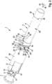
- the Figs. 1 to 3 show a kit 1 comprising a deep sea valve actuator 2 and a tool 3, wherein the tool 3 comprises a tool holder 4 with a at least in one direction axially fixed but rotatably mounted thereon, wherein the deep-sea valve actuator 2 has a first end 6 which is prepared for detachable coupling to a deep-sea valve 7, wherein the deep-sea valve actuator 2 has an actuator 8 which is surrounded by a connecting sleeve 9 which is rotatable relative to it, wherein the connecting sleeve 9 has at least one axial movement blocking projection 10 on the side of the first end 6 which is prepared for engaging behind a projection 11 of a valve and the actuator 8 has a pin 12 for bearing against the projection 11 of the valve in a way that prevents rotation, wherein the deep-sea valve actuator 2 has a second end 13 which is provided for detachable coupling to the tool 3, wherein for this purpose the connecting sleeve 9 has a reces
- the Fig.1 is a perspective view of the kit 1, in which the tool 3 is coupled to the deep sea valve actuator 2.
- the deep sea valve actuator 2 is also coupled to the deep sea valve 7.
- the kit 1 is in the illustrated Fig. 1 in an intermediate position.
- the axial movement blocking projection 10 is not in a completely engaging position of the projection 11, but is rotated into an intermediate position in the circumferential direction 19.
- a part of the connecting sleeve 9 is hidden in order to illustrate the locking geometry of the deep-sea valve actuator 2 with the deep-sea valve 7.
- the deep sea valve 7 has a plurality of projections 11 which are arranged uniformly/constantly relative to one another in the circumferential direction. are spaced apart. Attention is drawn to the Fig. 5 which represents the standardized connection geometry of the deep sea valve 7.
- the actuator 8 also has a plurality of pins 12, which are designed as counterparts to the projections 11 of the deep-sea valve 7, so that a pin 12 is inserted between two projections 11. The resulting plug connection of pins 12 and projections 11 prevents rotational movement.
- the actuator 8 is surrounded by a connecting sleeve 9.
- the axial movement blocking projections 10 are formed on the side of the first end 6.
- the connecting sleeve 9 has a plurality of axial movement blocking projections 10 which corresponds to the number of projections 11 of the deep sea valve 7.
- the connecting sleeve 9 has and is surrounded by a cover 20 which protects the actuator 8.
- the connecting sleeve 9 has a two-stage shoulder 21, 22 with two different diameters at the second end 13.
- An opening 23 is integrated in the shoulder with the larger diameter, a first shoulder 21, with which an indication of the coupling state of the deep-sea valve actuator 2 with the deep-sea valve 7 can be shown.
- Indicators 24, 25 applied to the actuator 8 (see Fign. 2 and 3 ) a distinction can be made between an unlocking/removal position and a locking/fastening position. As shown, the letters "U” and "L” are used as examples for the English terms "Unlocked” and "Locked".
- the recess 14 is formed in the second shoulder 22, the one with the smaller diameter.
- this shoulder 22 has two recesses 14 that are arranged 180° apart from each other.
- the contour of the recess 14 is U-shaped in the axial direction 18.
- the second end 13 of the deep sea valve actuator 2 has the radial projection 16, which in the decoupled state (see Fig. 3 ) has the same orientation as the recess 14, so that the tool 3 can be pushed on in the axial direction.
- the tool 3 has the tool holder 4 and the coupling sleeve 5.
- the tool holder 4 has two different shoulders 26, 27, the second shoulder 27 having a larger diameter than the first shoulder 26.
- the axial projection 17 of the tool holder 4 is formed on the second shoulder 27. This axial projection 17 has a counter shoulder 28.
- the tool holder 4 has two axial projections 17, which are oriented according to the radial projections 16 of the actuator 8.
- the locking lever 15 of the coupling sleeve 5 has a separate shoulder 29. This shoulder 29 engages the counter shoulder 28 of the axial projection 17 of the tool 3 so that rotation in a first direction of rotation 30 (here clockwise) of the locking lever 15 is limited. This is implemented by means of a positive locking.
- the coupling sleeve 5 has an actuating lever 31.
- actuating lever 31 By means of this actuating lever 31, a rotary movement in the first direction of rotation 30 and in a second direction of rotation 32, the opposite direction of rotation to the first direction of rotation 30, can be carried out in the circumferential direction 19.
- the coupling sleeve 5 also has openings 33, 34, which serve to indicate the coupling state of the tool 3.
- a distinction can be made between a coupled and uncoupled state of the deep-sea valve actuator 2 with the tool 3.
- the letters "U” and "L” are used as examples for the English terms "unlocked” and "locked”.
- the coupling sleeve 5 of the tool holder 4 is rotated in the circumferential direction 19 in the first direction of rotation 30 (counterclockwise). According to the opening 23 in the second shoulder 22 of the connecting sleeve 9, no indicator 24, 25 for the coupling state is shown. This is a feature of the intermediate position.
- the connecting sleeve 9 is rotated by the positive engagement of the locking lever 15 with the recess 14. This also causes the axial movement blocking projections 10 on the side of the first end 6 to rotate and the intermediate position shown follows.
- Fig. 2 the rotation of the coupling sleeve 5 in the first direction of rotation 30 is complete. This can be seen from the fact that the axial movement blocking projections 10 are flush with the pins 12.
- the unlocking/removal position has been reached.
- the deep-sea valve actuator 2 is thus released from the deep-sea valve 7 and can be removed in the axial direction 18.
- the indicator 24 of the actuator 8 shows the symbol "U", which indicates the unlocking/removal position.
- the locking lever 15 has reached the end position and can preferably not be rotated any further.
- the coupled state can be removed through the opening 34 using the second indicator 36 in the tool holder.
- Fig. 3 the deep sea valve actuator 2 is shown in the locking/fastening position on the deep sea valve 7. This can be identified by the indicator 25 in the opening 23 in the second shoulder 22 of the connecting sleeve 9, the indicator in the shape of an "L".
- the tool 2 is also shown, which is also in a decoupled state, which can also be seen from the associated indicator 35, the "U" through the opening 33.
- the locking lever 15 is aligned flush with the axial projection 17 in the axial direction 18.
- the shoulder 29 and the counter shoulder 28 are arranged in a form-fitting manner.
- a connection 38 for a plug connection is formed in an end wall 37 of the actuator 8, wherein according to Fig. 4 an electrical plug 39 can be inserted there.
- Fig. 5 The connection for the deep sea valve is shown in a perspective view. According to the embodiment shown there, the Deep sea valve 7 has four projections. The exact design can be found in DIN EN ISO 13628-8:2008-03.
Landscapes
- Engineering & Computer Science (AREA)
- Life Sciences & Earth Sciences (AREA)
- Geology (AREA)
- Mining & Mineral Resources (AREA)
- Physics & Mathematics (AREA)
- Environmental & Geological Engineering (AREA)
- Fluid Mechanics (AREA)
- General Life Sciences & Earth Sciences (AREA)
- Geochemistry & Mineralogy (AREA)
- Mechanical Engineering (AREA)
- Mechanically-Actuated Valves (AREA)
- Preventing Unauthorised Actuation Of Valves (AREA)
Abstract
Description
- Die Erfindung betrifft einen Bausatz aus einem Tiefseeventilaktuator und einem Werkzeug.
- Ein Tiefseeventilaktuator (im Englischen: subsea valve actuator, kurz: SVA) ist ein autarker Aktuator zum Öffnen und Schließen von Prozessventilen in der Tiefsee bis 3000 Meter und tiefer. Das System besteht aus einem elektrisch geregelten Antrieb mit einem hydrostatischen Getriebe, das im Vergleich zu einer herkömmlichen elektromechanischen Achse bis zu 75 Prozent der benötigten Energie einspart. Der Tiefseeventilaktuator öffnet und schließt Prozessventile in Anwendungen für die Öl- und Gas-Produktion oder CO2-Speichersysteme in der Tiefsee. Eine redundante Ausführung von z.B. Sicherheitsventilen und bewährten Federn sorgt dafür, dass der Aktuator auch bei Stromausfall und ohne externe Energiezufuhr das Prozessventil sicher schließt. Alle relevanten Bauteile des Antriebsstrangs sind doppelt ausgeführt.
- Das System ist für den Einsatz in der Tiefsee bis 3000 Meter und tiefer geeignet und auf einen wartungsfreien Betrieb von 25 Jahren ausgelegt. Der Tiefseeventilaktuator ist eine Schlüsselkomponente, um die Elektrifizierung der Produktionsanlagen in der Tiefsee weiter voranzubringen.
- In Anwendungen wie z.B. dem Einbau der Tiefseeventilaktuatoren in einem Ventilgestell auf einem Bohrloch für Öl oder CO2 Speicherung sind die Tiefseeventilaktuator- Ventile oder andere Bauteile so dicht zueinander verbaut, dass der Zugang bevorzugt nur von hinten erfolgen kann. Eine Aufnahme zum Ausbau des Tiefseeventilaktuators durch ein ferngesteuertes Unterwasserfahrzeug (im Englischen: remotely operated underwater vehicle, kurz: ROV) im Schwerpunkt der Achse ist größtenteils nicht möglich, da in der Regel der Tiefseeventilaktuator horizontal verbaut ist und umliegende Bauteile keine Möglichkeit zur Aufnahme im Schwerpunkt erlauben.
- Nach dem Stand der Technik sind Ventilaktautoren in der Tiefsee nicht leicht austauschbar, besitzen auch keine standardisierte Schnittstelle zum Aus- und Einbau des Ventilaktuators. In der Regel sind unter Wasser verbaute Ventilaktuatoren nur durch Taucher oder komplettes Heben der Ventileinheiten möglich. Ein Wechsel des Ventilaktuators durch Tauchroboter in größeren Tiefen ist kaum möglich.
- Die Aufgabe der vorliegenden Erfindung ist es, die angesprochenen Nachteile zu beseitigen oder zumindest (teilweise) zu lindern.
- Dies wird bei einem vorliegenden Bausatz aus einem Tiefseeventilaktuator und einem Werkzeug dadurch gelöst, dass das Werkzeug einen Werkzeughalter mit einer zumindest in einer Richtung axial festen, aber drehbeweglich darauf gelagerten Koppelhülse, besitzt, wobei der Tiefseeventilaktuator ein erstes Ende besitzt, das zum lösbaren Koppeln an einem Tiefseeventil (Englisch: subsea valve) vorbereitet ist, wobei der Tiefseeventilaktuator einen Linear- / Rotations- Aktuator besitzt, der von einer für ihn drehbeweglichen Verbindungshülse zumindest teilweise / vollständig umgeben ist, wobei die Verbindungshülse auf der Seite des ersten Endes wenigstens einen Axialbewegungsblockiervorsprung besitzt, der zum Hintergreifen eines Vorsprungs eines beispielsweise nach ISO 13628-8: 2008-03 genormten Tiefseeventils vorbereitet ist und der Linear- / Rotations-Aktuator einen Zapfen zum drehbewegungsverhindernden Anliegen an den Vorsprung des Ventils besitzt, wobei der Tiefseeventilaktuator ein zweites Ende besitzt, das zum lösbaren Koppeln an dem Werkzeug vorgesehen ist, wobei dafür die Verbindungshülse eine Ausnehmung zum Aufnehmen eines Verriegelungshebels der Koppelhülse besitzt, über den eine Drehbewegung der Verbindungshülse hervorrufbar ist, und der Aktuator einen Radialvorsprung besitzt, der an einem Axialvorsprung des Werkzeughalters anliegt, wobei der Verriegelungshebel vorbereitet ist, die Verbindungshülse bei dazu vom Axialvorsprung in seiner Ausgangslage gehaltenen Aktuator in eine hintergriffgelöste Entriegel-/Entnahmeposition zu verbringen. Vorteilhaft hierbei ist die Vereinfachung des Wechselvorgangs des Tiefseeventilaktuators an einem Tiefseeventil. Insbesondere der Einsatz mittels eines Unterwassertauchroboters wird damit ermöglicht.
- Der Bausatz aus Tiefseeventilaktuator und Werkzeug kann verschiedene Zustände / Positionen einnehmen. Es ist zwischen einem entkoppelten Zustand und gekoppelten Zustand von dem Tiefseeventilaktuator mit dem Werkzeug zu unterscheiden. In dem entkoppelten Zustand sind der Tiefseeventilaktuator und das Werkzeug voneinander getrennt. In einem gekoppelten Zustand ist das Werkzeug mit dem Tiefseeventilaktuator verbunden und befindet sich im Eingriff mit diesem.
- In der Entriegel-/Entnahmeposition ist der Tiefseeventilaktuator von dem Tiefseeventil gelöst, ergo findet kein Hintergreifen des Axialbewegungsblockiervorsprungs hinter dem Vorsprung des Tiefseeventils statt.
- In einer Verriegel-/Befestigungsposition ist der Tiefseeventilaktuator an dem Tiefseeventil festgelegt. Dabei findet ein Hintergreifen des Axialbewegungsblockiervorsprungs hinter dem Vorsprung des Tiefseeventils statt.
- Für das Erreichen der Entriegel-/Entnahmeposition bzw. der Verriegel-/Befestigungsposition ist der gekoppelter Zustand des Werkzeugs mit dem Tiefseeventilaktuator vorgesehen.
- Für den gekoppelten bzw. entkoppelten Zustand und das Erreichen der Entriegel-/Entnahmeposition bzw. der Verriegel-/Befestigungsposition sind voneinander verschiedene Drehbewegungen gegeben. Eine erste Drehrichtung und eine zweite Drehrichtung, wobei die zweite Drehrichtung in eine von der ersten Drehrichtung entgegengesetzte Drehrichtung dreht. Die erste Drehrichtung erfolgt in Umfangsrichtung gegen den Uhrzeigersinn, wobei die zweite Drehrichtung in Umfangsrichtung entgegengesetzt, also mit dem Uhrzeigersinn, verläuft. Für den gekoppelten Zustand ist eine Drehbewegung in die erste Drehrichtung getätigt, für den entkoppelten Zustand ist eine Drehbewegung in die zweite Drehrichtung getätigt.
- Vorteilhafte Ausführungsformen sind in den Unteransprüchen beansprucht und werden nachfolgend näher erläutert.
- Außerdem kann die Verbindungshülse ein- oder mehrteilig ausgebildet ist. Ein mehrteiliger Aufbau fördert eine Modularität, welche in weiteren Aspekten dieser Anmeldung näher ausgeführt ist.
- Des Weiteren kann die Verbindungshülse mittels einem ersten Ring / ringförmigen Element am ersten Ende des Tiefseeventilaktuators und einem zweiten Ring / ringförmigen Element am zweiten Ende des Tiefseeventilaktuators gebildet sein. Bevorzugt ist, dass der erste Ring und der zweite Ring drehfest miteinander verbunden sind. Damit ist vorgesehen, dass eine Übertragung der Drehbewegung vom zweiten Ende in Richtung ersten Endes stattfinden kann. Besonders bevorzugt ist, wenn der erste Ring und der zweite Ring über einen Steg miteinander drehfest verbunden sind. Beispielsweise sind der erste Ring und der zweite Ring über den Steg, der sich in Axialrichtung entlang des Aktuators erstreckt, verbunden. Der Steg ist dabei rippenförmig ausgebildet, um zum einen die Montage zu vereinfachen, aber auch um nicht notwendiges Material einzusparen.
- In einer weiteren vorteilhaften Ausführungsform ist das zweite Ende des Tiefseeventilaktuators ein vom Aktuator separates Bauteil, wobei an dem separaten Bauteil der Radialvorsprung ausgebildet ist. Damit ist eine modulare Bauweise gegeben. Das in der vorliegenden Ausführungsform separate zweite Ende ist mit dem Aktuator drehfest verbunden, wodurch sich das separate zweite Ende nicht um die eigene Achse drehen kann.
- Von Vorteil ist, wenn die Anzahl von Verriegelungshebeln eins, zwei, drei oder eine Vielzahl ist. Zumindest zwei Verriegelungshebel erleichtern ein Aufschieben des Werkezugs und ein Verdrehen in Umfangsrichtung.
- Bevorzugt sind die Verriegelungshebel in Umfangsrichtung zueinander gleichmäßig verteilt. Je nach Anzahl an Verriegelungshebeln entstehen dabei Winkelabstände von 180°, 120°, 90° etc..
- Es hat sich als zweckmäßig herausgestellt, wenn die Anzahl an Ausnehmungen der Anzahl an Verriegelungshebeln entspricht. Dabei kann die Anzahl an Ausnehmungen in der Verbindungshülse ebenfalls eins, zwei, drei oder eine Vielzahl sein. Dies unterstützt somit auch das Aufschieben des Werkzeugs und das Verdrehen in Umfangsrichtung.
- In einer weiteren Ausführungsform weist die Ausnehmung der Verbindungshülse eine rechteckig Forma auf. Besonders bevorzugt ist die Kontur der Ausnehmung U-förmig gestaltet. Insbesondere ist die Geometrie /Form des Verriegelungshebels so ausgestaltet, dass ein Formschluss mit der Ausnehmung gebildet ist. Alternativ kann der Formschluss zwischen Verriegelungshebel und Ausnehmung auch andere geometrische Formen aufweisen, beispielsweise eine halbkreisförmige Form, gebildet sein. Durch die formschlüssige Verbindung ist die Übertragung eines Drehmoments von Koppelhülse auf Verbindungshülse möglich.
- Von Vorteil ist, wenn der Verriegelungshebel einen Absatz aufweist, damit die Koppelhülse in der Drehbewegung in Umfangsrichtung begrenzt ist. Damit kann sichergestellt werden, dass ein Überdrehen erschwert wird.
- Bevorzugt weist der Axialvorsprung einen in Umfangsrichtung zu dem Absatz des Verriegelungshebels passenden Gegenabsatz auf. Besonders bevorzugt bilden der Verriegelungshebel und der Axialvorsprung mittels des Absatzes und des Gegenabsatz eine Drehsicherung. Damit ist sichergestellt, dass die Drehung in Umfangsrichtung in die erste Drehrichtung begrenzt ist und ein Überdrehen verhindert ist.
- Außerdem kann der Aktuator einen Verriegelungsindikator aufweisen, anhand dessen der gekoppelte und entkoppelte Zustand unterscheidbar ist. Bevorzugt sind dazu in dem Aktuator an einer vorderen Stirnseite, die zum Werkzeug orientiert ist, Markierungen angebracht / eingebracht, die eine Identifikation beim Drehen der Verbindungshülse zulassen. Vorteilhaft ist dabei, dass bei Anwendung des Werkzeugs durch einen Taucher oder Unterwasserroboter/-fahrzeug (dann bevorzugt über eine Videokamera) erkennbar ist, wann der gekoppelte bzw. entkoppelte Zustand erreicht ist und ein Überdrehen in Umfangsrichtung minimiert / reduziert ist.
- Vorzugsweise weist das zweite Ende des Tiefseeventilaktuators eine Aufnahme für eine elektrische Steckverbindung auf, die in dem zweiten Ende integriert ist. Bevorzugt ist die Aufnahme in einer Stirnseite des Tiefseeventilaktuators in Axialrichtung positioniert. Durch diese Positionierung ist zum einen Bauraum eingespart, aber auch ist eine Beschädigung des Anschlusses verhindert.
- In einer weiteren Ausführungsform weist die Koppelhülse einen Betätigungshebel auf, der vorzugsweise von einem Tiefseeunterwasserroboter (oder einem Taucher) betätigt werden kann. Der Betätigungshebel erleichtert dabei das Verdrehen in Umfangsrichtung, um die Verbindungshülse in die Verriegel-/Befestigungsposition bzw. Entriegel-/Entnahmeposition zu überführen.
- Vorzugsweise ist eine Palette in der Nähe der Tiefseeventilaktuatoren vorhanden, die eine Lagerfunktion für defekte und intakte Tiefseeventilaktuatoren bereitstellt. Damit ist sichergestellt, dass der Aus- und Einbau von neuen Tiefseeventilaktuatoren weniger aufwändig durchgeführt werden kann.
- Des Weiteren kann der Axialbewegungsblockiervorsprung der Verbindungshülse auf der werkzeugabgewandten Seite des Vorsprungs des Ventils anliegen und/oder der Zapfen des Linear/Rotations-Aktuators an einer Seite des Vorsprungs des Ventils anliegen.
- Die Erfindung betrifft auch ein Verfahren zum Koppeln eines Werkzeugs mit einem Tiefseeventilaktuator eines Bausatzes, vorzugsweise gemäß der zuvor genannten Vorrichtung, wobei in einem ersten Schritt das Werkzeug an ein zweites Ende des Tiefseeventilaktuators in Axialrichtung aufgeschoben wird und dabei ein Verriegelungshebel einer Koppelhülse des Werkzeugs in eine Ausnehmung einer Verbindungshülse des Tiefseeventilaktuators eingreift, wobei ebenfalls ein Axialvorsprung des Werkzeugs an einem Radialvorsprung eines Aktuators des Tiefseeventilaktuators anliegt und in einem zweiten Schritt mit einer Drehbewegung der Koppelhülse in Umfangsrichtung in einer ersten Drehrichtung der Verriegelungshebel durch die Drehbewegung die Verbindungshülse im Gleichschritt in Umfangsrichtung in der ersten Drehrichtung mitdreht, wodurch eine Koppelung zwischen Werkzeug und Tiefseeventilaktuator gebildet wird.
- Auch betrifft die Erfindung ein Verfahren zum Entkoppeln eines Werkzeugs mit einem Tiefseeventilaktuator eines Bausatzes, vorzugsweise gemäß der zuvor genannten Vorrichtung, wobei durch eine Drehbewegung in Umfangsrichtung in einer zweiten Drehrichtung die Kopplung mittels der Koppelhülse zwischen dem Werkzeug und dem Tiefseeventilaktuator gelöst wird und das Werkzeug von dem Tiefseeventilaktuator in Axialrichtung abnehmbar ist.
- In anderen Worten wird ein Tiefseeventilaktuator mittels eines Werkzeuges, was von einem ferngesteuerten Unterwasserfahrzeug/-roboter (kurz: ROV) gehalten wird, über eine Werkzeug Kopplung von hinten (entgegensetzt einer Ventilantriebsseite) auf den Tiefseeventilaktuator geschoben.
- Bevorzugt ist durch die Bedienung des Werkzeugs durch das Unterwasserfahrzeug im ersten Schritt der Tiefseeventilaktuator mit dem Werkzeug verriegelt und im zweiten Schritt die Schnittstelle an der Ventilantriebsseite des Tiefseeventilaktuators entkoppelt, um den Tiefseeventilaktuator entfernen zu können. Hierbei ist es vorteilhaft, die beiden Arbeitsschritte über eine Vorrichtung und in einem Vorgang erfolgen zu lassen.
- Vorteilhaft ist die Bereitstellung einer Vorrichtung beispielsweise in Form einer Palette auf dem Meeresboden, die den alten / ausgetauschten Tiefseeventilaktuator aufnimmt und auch den Ersatztiefseeventilaktuator beinhaltet, wobei die Befestigungsaufnahmen dem Verschluss am Ventil entspricht, wobei das Unterwasserfahrzeug den Tiefseeventilaktuator hier einkuppelt, so wie das neue Ventil aufnehmen kann.
- Bevorzugt erfolgt das Entkoppeln der Tiefseeventilaktuators vom Werkzeug durch entgegensetzte Vorgehensweise wie das Koppeln, wobei erst der Tiefseeventilaktuator mit dem antriebsseitigen Verschluss gekoppelt wird und dann erst vom Werkzeug entkoppelt wird, wobei beim Übergang der beiden Schritte die Achse sicher im Werkzeug verbunden ist.
- Aus Platzgründen ist der elektrische Steckanschluss des Tiefseeventilaktuators in der hinteren Werkzeugkopplung integriert. Dieser ist so im Anschluss integriert, dass eine Beschädigung beim Tiefseeventilaktuatorwechsel ausgeschlossen ist. Vorteilhaft ist auch, dass bei eingestecktem Elektrostecker das Werkzeug nicht auf die Werkzeugkopplung aufgesteckt werden kann, was die Montagereihenfolge zwangsweise vorgibt und dann nicht zur Beschädigung der Anschlusskabel führt.
- Verschiedene vorteilbehaftete Ausführungsformen der Erfindung werden nachfolgend anhand einer Zeichnung mit Figuren näher erläutert.
- Es zeigt:
- Fig. 1
- eine Zwischenposition zwischen einem Tiefseeventilaktuator und einem Werkzeug in einer perspektivischen Ansicht,
- Fig. 2
- der Tiefseeventilaktuator in einer Entriegel-/Entnahmeposition mit gekoppeltem Werkzeug in einer perspektivischen Ansicht,
- Fig. 3
- der Tiefseeventilaktuator in einer Verriegel-/Befestigungsposition und entkoppeltem Werkzeug in einer perspektivischen Ansicht,
- Fig. 4
- den Tiefseeventilaktuator in der Verriegel-/Befestigungsposition mit elektrischer Steckverbindung in einer perspektivischen Ansicht,
- Fig. 5
- eine perspektivische Ansicht des Tiefseeventils nach ISO-Norm.
- Die Figuren sind lediglich schematischer Natur und dienen ausschließlich dem Verständnis der Erfindung. Die gleichen Elemente sind mit denselben Bezugszeichen versehen. Merkmale der einzelnen Ausführungsformen lassen sich untereinander austauschen und alternativ / kumulativ einsetzen.
- Die
Fign. 1 bis 3 zeigen einen Bausatz 1 aus einem Tiefseeventilaktuator 2 und einem Werkzeug 3, wobei das Werkzeug 3 einen Werkzeughalter 4 mit einer zumindest in einer Richtung axial festen, aber drehbeweglich darauf gelagerten Koppelhülse 5 besitzt, wobei der Tiefseeventilaktuator 2 ein erstes Ende 6 besitzt, das zum lösbaren Koppeln an einem Tiefseeventil 7 vorbereitet ist, wobei der Tiefseeventilaktuator 2 einen Aktuator 8 besitzt, der von einer zu ihm drehbeweglichen Verbindungshülse 9 umgeben ist, wobei die Verbindungshülse 9 auf der Seite des ersten Endes 6 wenigstens einen Axialbewegungsblockiervorsprung 10 besitzt, der zum Hintergreifen eines Vorsprungs 11 eines Ventils vorbereitet ist und der Aktuator 8 einen Zapfen 12 zum drehbewegungsverhindernden Anliegen an den Vorsprung 11 des Ventils besitzt, wobei der Tiefseeventilaktuator 2 ein zweites Ende 13 besitzt, das zum lösbaren Koppeln an dem Werkzeug 3 vorgesehen ist, wobei dafür die Verbindungshülse 9 eine Ausnehmung 14 zum Aufnehmen eines Verriegelungshebels 15 der Koppelhülse 5 besitzt, über den eine Drehbewegung der Verbindungshülse 9 hervorrufbar ist, und der Aktuator 8 einen Radialvorsprung 16 besitzt, der an einem Axialvorsprung 17 des Werkzeughalters 4 anliegt, wobei der Verriegelungshebel 15 vorbereitet ist, die Verbindungshülse 9 bei dazu vom Axialvorsprung 17 in seiner Ausgangslage gehaltenen Aktuator 8 in eine hintergriffgelöste Entriegel-/Entnahmeposition zu verbringen. - Zur Verdeutlichung der Darstellungen ist eine Axialrichtung 18 und eine Umfangsrichtung 19 dargestellt.
- Die
Fig.1 ist eine perspektivische Ansicht des Bausatzes 1, bei der das Werkzeug 3 an dem Tiefseeventilaktuator 2 gekoppelt ist. Ebenfalls ist der Tiefseeventilaktuator 2 an dem Tiefseeventil 7 gekoppelt. Der Bausatz 1 ist in der dargestelltenFig. 1 in einer Zwischenposition gezeigt. Der Axialbewegungsblockiervorsprung 10 ist dabei nicht in einer vollständigen Hintergreifposition des Vorsprungs 11, sondern ist in eine Zwischenposition in der Umfangsrichtung 19 gedreht. Zur besseren Verdeutlichung ist ein Teil der Verbindungshülse 9 ausgeblendet, um die Verriegelgeometrie des Tiefseeventilaktuators 2 mit dem Tiefseeventil 7 zu verdeutlichen. - In der dargestellten Ausführungsform weist das Tiefseeventil 7 eine Vielzahl an Vorsprüngen 11 auf, die in Umfangsrichtung gleichmäßig / konstant zueinander beabstandet sind. Hierbei ist auf die
Fig. 5 verwiesen, die die genormte Anschlussgeometrie des Tiefseeventils 7 darstellt. - Der Aktuator 8 weist ebenfalls eine Vielzahl an Zapfen 12 auf, die entsprechend als Gegenpart zu den Vorsprüngen 11 des Tiefseeventils 7 ausgebildet sind, so dass ein Zapfen 12 zwischen zwei Vorsprüngen 11 eingesteckt ist. Die damit gegebene Steckverbindung aus Zapfen 12 und Vorsprüngen 11 ist drehbewegungsverhindernd.
- Der Aktuator 8 ist von einer Verbindungshülse 9 umgeben. In der dargestellten Ausführungsform sind die Axialbewegungsblockiervorsprünge 10 auf der Seite des ersten Endes 6 ausgebildet. Hierbei weist die Verbindungshülse 9 eine Vielzahl an Axialbewegungsblockiervorsprüngen 10 auf, die der Anzahl an Vorsprüngen 11 des Tiefseeventils 7 entspricht. Die Verbindungshülse 9 hat eine Abdeckung 20 und ist von dieser umgeben, die den Aktuator 8 schützt.
- Die Verbindungshülse 9 weist am zweiten Ende 13 einen zweistufigen Absatz 21, 22 mit zwei voneinander unterschiedlichen Durchmessern auf. In dem Absatz mit dem größeren Durchmesser, einem ersten Absatz 21, ist eine Öffnung 23 integriert, mit der eine Indikation des Kopplungszustands von Tiefseeventilaktuator 2 mit dem Tiefseeventil 7 darstellbar ist. Durch in den Aktuator 8 aufgebrachte Indikatoren 24, 25 (siehe
Fign. 2 und3 ) ist zwischen einer Entriegel-/Entnahmeposition und einer Verriegel-/Befestigungsposition unterscheidbar. Darstellungsgemäß sind die die Buchstaben "U" und "L", für die englischen Begriffe "Unlocked" und "Locked", beispielhaft genutzt. - In dem zweiten Absatz 22, dem mit dem kleineren Durchmesser, ist die Ausnehmung 14 gebildet. In der dargestellten Ausführungsform weist dieser Absatz 22 zwei Ausnehmungen 14 auf, die im 180° Abstand zueinander angeordnet sind. Die Kontur der Ausnehmung 14 ist in der dargestellten Ausführungsform in der Axialrichtung 18 U-förmig.
- Das zweite Ende 13 des Tiefseeventilaktuators 2 weist den Radialvorsprung 16 auf, der im entkoppelten Zustand (siehe
Fig. 3 ) die gleiche Ausrichtung aufweist wie die Ausnehmung 14, so dass das Werkzeug 3 in Axialrichtung aufschiebbar ist. - Das Werkzeug 3 weist den Werkzeughalter 4 und die Koppelhülse 5 auf. Der Werkzeughalter 4 weist zwei voneinander unterschiedliche Absätze 26, 27 auf, wobei der zweite Absatz 27 einen größeren Durchmesser aufweist als der erste Absatz 26. An dem zweiten Absatz 27 ist der Axialvorsprung 17 des Werkzeughalters 4 ausgebildet. Dieser Axialvorsprung 17 weist einen Gegenabsatz 28 auf. In der dargestellten Ausführungsform weist der Werkzeughalter 4 zwei Axialvorsprünge 17 auf, die gemäß zu den Radialvorsprüngen 16 des Aktuators 8 orientiert sind.
- Der Verriegelungshebel 15 der Koppelhülse 5 weist einen separaten Absatz 29 auf. Dieser Absatz 29 greift an dem Gegenabsatz 28 des Axialvorsprungs 17 des Werkzeugs 3 an, damit ein Verdrehen in eine erste Drehrichtung 30 (hier mit dem Uhrzeigeersinn) des Verriegelungshebels 15 begrenzt ist. Dies ist mittels eines Formschluss umgesetzt.
- Die Koppelhülse 5 weist einen Betätigungshebel 31 auf. Mittels diesem Betätigungshebel 31 ist in der Umfangsrichtung 19 eine Drehbewegung in die erste Drehrichtung 30 und in eine zweite Drehrichtung 32, der entgegengesetzten Drehrichtung zur ersten Drehrichtung 30, vollziehbar. Die Koppelhülse 5 weist zudem Öffnungen 33, 34 auf, die zur Indikation des Kopplungszustands des Werkzeugs 3 dienen. Hierbei ist zwischen einem gekoppelten und entkoppelten Zustand des Tiefseeventilaktuators 2 mit dem Werkzeug 3 unterscheidbar. Darstellungsgemäß sind die die Buchstaben "U" und "L", für die englischen Begriffe "Unlocked" und "Locked", beispielhaft genutzt.
- In der dargestellten Zwischenposition ist die Koppelhülse 5 des Werkzeughalters 4 in der Umfangsrichtung 19 in die erste Drehrichtung 30 (gegen den Uhrzeigeersinn) gedreht. Gemäß der Öffnung 23 im zweiten Absatz 22 der Verbindungshülse 9 ist kein Indikator 24, 25 für den Kopplungszustand gezeigt. Dies ist ein Merkmal für die Zwischenposition. Bei der Drehung der Koppelhülse 5 in der ersten Drehrichtung 30 wird durch den Formschluss des Verriegelungshebels 15 mit der Ausnehmung 14 die Verbindungshülse 9 mitgedreht. Damit drehen sich ebenfalls die Axialbewegungsblockiervorsprünge 10 auf der Seite des ersten Endes 6 und es folgt die dargestellte Zwischenposition.
- In
Fig. 2 ist die Drehung der Koppelhülse 5 in der ersten Drehrichtung 30 abgeschlossen. Dies ist daran zu erkennen, dass die Axialbewegungsblockiervorsprünge 10 bündig mit den Zapfen 12 sind. Die Entriegel-/Entnahmeposition ist erreicht. Damit ist der Tiefseeventilaktuator 2 von dem Tiefseeventil 7 gelöst und in Axialrichtung 18 abnehmbar. Des Weiteren zeigt der Indikator 24 des Aktuators 8 das Symbol "U", was auf die Entriegel-/Entnahmeposition hinweist. Der Verriegelungshebel 15 ist dabei in der Endposition angelangt und lässt sich vorzugsweise nicht weiterdrehen. Mittels des zweiten Indikators 36 in dem Werkzeughalter kann der gekoppelte Zustand durch die Öffnung 34 entnommen werden. - In
Fig. 3 ist der Tiefseeventilaktuator 2 in der Verriegel-/Befestigungsposition am Tiefseeventil 7 dargestellt. Dies ist am Indikator 25 in der Öffnung 23 im zweiten Absatz 22 der Verbindungshülse 9, dem indikator in der Form des "L", identifizierbar. Ebenfalls ist das Werkzeug 2 dargestellt, welches sich ebenfalls in einem entkoppelten Zustand befindet, was auch dem zugehörigen Indikator 35, dem "U" durch die Öffnung 33 entnehmbar ist. Der Verriegelungshebel 15 ist in Axialrichtung 18 bündig mit dem Axialvorsprung 17 ausgerichtet. Dabei sind der Absatz 29 und der Gegenabsatz 28 formschlüssig angeordnet. Am zweiten Ende 13 ist in einer Stirnwand 37 des Aktuators 8 ein Anschluss 38 für eine Steckverbindung ausgebildet, wobei gemäßFig. 4 ein elektrischer Stecker 39 dort einsteckbar ist. - Mithilfe des ausgeblendeten Teils der Verbindungshülse 9 ist das komplette Hintergreifen der Axialbewegungsblockvorsprünge 10 an den Vorsprüngen 11 erkennbar.
- Gemäß
Fig. 5 ist der Anschluss für das Tiefseeventil in einer perspektivischen Darstellung gezeigt. Gemäß der dort dargestellten Ausführungsform weist das Tiefseeventil 7 vier Vorsprünge auf. Die genaue Ausgestaltung kann der DIN EN ISO 13628-8:2008-03 entnommen werden.
Claims (10)
- Bausatz (1) aus einem Tiefseeventilaktuator (2) und einem Werkzeug (3), wobei das Werkzeug (3) einen Werkzeughalter (4) mit einer zumindest in eine Richtung axialfesten, aber drehbeweglich darauf gelagerten Koppelhülse (5), besitzt, wobei der Tiefseeventilaktuator (2) ein erstes Ende (6) besitzt, das zum lösbaren Koppeln an einem Tiefseeventil (7) vorbereitet ist, wobei der Tiefseeventilaktuator (2) einen Aktuator (8) besitzt, der von einer zu ihm drehbeweglichen Verbindungshülse (9) umgeben ist, wobei die Verbindungshülse (9) auf der Seite des ersten Endes (6) wenigstens einen Axialbewegungsblockiervorsprung (10) besitzt, der zum Hintergreifen eines Vorsprungs (11) eines Ventils vorbereitet ist und der Aktuator (8) einen Zapfen (12) zum drehbewegungsverhindernden Anliegen an den Vorsprung (11) des Ventils besitzt, wobei der Tiefseeventilaktuator (2) ein zweites Ende (13) besitzt, das zum lösbaren Koppeln an dem Werkzeug (3) vorgesehen ist, wobei dafür die Verbindungshülse (9) eine Ausnehmung (14) zum Aufnehmen eines Verriegelungshebels (15) der Koppelhülse (5) besitzt, über den eine Drehbewegung der Verbindungshülse (9) hervorrufbar ist, und der Aktuator (8) einen Radialvorsprung (16) besitzt, der an einem Axialvorsprung (17) des Werkzeughalters (4) anliegt, wobei der Verriegelungshebel (15) vorbereitet ist, die Verbindungshülse (9) bei dazu vom Axialvorsprung (17) in seiner Ausgangslage gehaltenen Aktuator (8) in eine hintergriffgelöste Entriegel-/Entnahmeposition zu verbringen.
- Bausatz (1) nach Anspruch 1, dadurch gekennzeichnet, dass die Verbindungshülse (9) ein- oder mehrteilig ausgebildet ist.
- Bausatz (1) nach Anspruch 2, dadurch gekennzeichnet, dass die Verbindungshülse (9) mittels einem ersten Ring am ersten Ende (6) des Tiefseeventilaktuators (2) und einem zweiten Ring am zweiten Ende (13) des Tiefseeventilaktuators (2) gebildet ist.
- Bausatz (1) nach Anspruch 3, dadurch gekennzeichnet, dass der erste Ring und der zweite Ring drehfest miteinander verbunden sind.
- Bausatz (1) nach einem der vorhergehenden Ansprüche, dadurch gekennzeichnet, dass das zweite Ende (13) des Tiefseeventilaktuators (2) ein vom Aktuator (8) separates Element ist.
- Bausatz (1) nach einem der vorhergehenden Ansprüche, dadurch gekennzeichnet, dass am zweiten Ende (13) des Tiefseeventilaktuators (2) eine Aufnahme für eine elektrische Steckverbindung integriert ist.
- Bausatz (1) nach einem der vorhergehenden Ansprüche, dadurch gekennzeichnet, dass die Anzahl von Verriegelungshebeln eins, zwei, drei oder eine Vielzahl ist.
- Bausatz (1) nach einem der Ansprüche 1 bis 7, wobei der Axialbewegungsblockiervorsprung (10) der Verbindungshülse (9) auf der werkzeugabgewandten Seite des Vorsprungs (11) des Ventils anliegt und/oder der Zapfen (12) des Aktuators (8) an einer Seite des Vorsprungs (11) des Ventils anliegt.
- Verfahren zum Koppeln eines Werkzeugs (3) mit einem Tiefseeventilaktuator (2) eines Bausatzes (1), wobei in einem ersten Schritt das Werkzeug (3) an ein zweites Ende (13) des Tiefseeventilaktuators (2) in Axialrichtung (18) aufgeschoben wird und dabei ein Verriegelungshebel (15) einer Koppelhülse (5) des Werkzeugs (3) in eine Ausnehmung (14) einer Verbindungshülse (9) des Tiefseeventilaktuators (2) eingreift, wobei ebenfalls ein Axialvorsprung (17) des Werkzeugs (3) an einem Radialvorsprung (16) eines Aktuators (8) des Tiefseeventilaktuators (2) anliegt und in einem zweiten Schritt mittels einer Drehbewegung in Umfangsrichtung (19) der Koppelhülse (5) in einer ersten Drehrichtung (30) der Verriegelungshebel (15) durch die Drehbewegung die Verbindungshülse (9) im Gleichschritt und Umfangsrichtung (19) in erster Drehrichtung (30) mitdreht, wodurch eine Kopplung zwischen Werkzeug (3) und Tiefseeventilaktuator (2) gebildet wird.
- Verfahren zum Entkoppeln eines Werkzeugs (3) mit einem Tiefseeventilaktuator (2) eines Bausatzes (1), wobei durch eine Drehbewegung in Umfangsrichtung (19) in einer zweiten Drehrichtung (32) die Kopplung mittels der Koppelhülse (5) zwischen dem Werkzeug (3) und dem Tiefseeventilaktuator (2) gelöst wird und das Werkzeug (3) von dem Tiefseeventilaktuator (2) in Axialrichtung (18) abnehmbar ist.
Applications Claiming Priority (1)
| Application Number | Priority Date | Filing Date | Title |
|---|---|---|---|
| DE102023204649.0A DE102023204649A1 (de) | 2023-05-17 | 2023-05-17 | Bausatz aus einem Tiefseeventilaktuator und einem Werkzeug |
Publications (2)
| Publication Number | Publication Date |
|---|---|
| EP4464868A1 true EP4464868A1 (de) | 2024-11-20 |
| EP4464868B1 EP4464868B1 (de) | 2025-12-03 |
Family
ID=91076524
Family Applications (1)
| Application Number | Title | Priority Date | Filing Date |
|---|---|---|---|
| EP24175433.2A Active EP4464868B1 (de) | 2023-05-17 | 2024-05-13 | Bausatz aus einem tiefseeventilaktuator und einem werkzeug |
Country Status (2)
| Country | Link |
|---|---|
| EP (1) | EP4464868B1 (de) |
| DE (1) | DE102023204649A1 (de) |
Citations (4)
| Publication number | Priority date | Publication date | Assignee | Title |
|---|---|---|---|---|
| US20110297392A1 (en) * | 2008-12-05 | 2011-12-08 | Cameron International Corporation | Sub-sea chemical injection metering valve |
| WO2015040476A2 (en) * | 2013-09-19 | 2015-03-26 | Petrolvalves S.R.L. | Mechatronic actuator for the automatic management of subsea valves |
| US20160153580A1 (en) * | 2013-04-22 | 2016-06-02 | Cameron International Corporation | Actuator |
| CN108086948A (zh) * | 2017-11-30 | 2018-05-29 | 江苏科技大学 | 一种水下阀门操作工具的锁定装置 |
Family Cites Families (4)
| Publication number | Priority date | Publication date | Assignee | Title |
|---|---|---|---|---|
| NO309439B1 (no) * | 1999-10-01 | 2001-01-29 | Kongsberg Offshore As | Anordning ved undervanns lubrikator, samt fremgangsmåter for utsirkulering av fluider fra den samme |
| US8181931B2 (en) * | 2009-01-06 | 2012-05-22 | Vetco Gray Inc. | Mechanically operated hydraulic valve actuator |
| NO341510B1 (no) * | 2012-11-15 | 2017-11-27 | Nat Coupling Co Inc | Forbedret dummy undersjøisk hydraulisk koplingselement |
| EP3953560B1 (de) * | 2019-04-10 | 2023-01-11 | TotalEnergies OneTech | Schutzvorrichtung für eine flüssigkeitsflussleitung, zugehörige installation und verfahren |
-
2023
- 2023-05-17 DE DE102023204649.0A patent/DE102023204649A1/de active Pending
-
2024
- 2024-05-13 EP EP24175433.2A patent/EP4464868B1/de active Active
Patent Citations (4)
| Publication number | Priority date | Publication date | Assignee | Title |
|---|---|---|---|---|
| US20110297392A1 (en) * | 2008-12-05 | 2011-12-08 | Cameron International Corporation | Sub-sea chemical injection metering valve |
| US20160153580A1 (en) * | 2013-04-22 | 2016-06-02 | Cameron International Corporation | Actuator |
| WO2015040476A2 (en) * | 2013-09-19 | 2015-03-26 | Petrolvalves S.R.L. | Mechatronic actuator for the automatic management of subsea valves |
| CN108086948A (zh) * | 2017-11-30 | 2018-05-29 | 江苏科技大学 | 一种水下阀门操作工具的锁定装置 |
Also Published As
| Publication number | Publication date |
|---|---|
| EP4464868B1 (de) | 2025-12-03 |
| DE102023204649A1 (de) | 2024-11-21 |
Similar Documents
| Publication | Publication Date | Title |
|---|---|---|
| DE19900064B4 (de) | Riegelvorrichtung für hydraulische Unterwasserkupplung | |
| DE602004009812T2 (de) | Verriegelungsvorrichtung für hergestellte rohrverbindungen | |
| DE3889919T2 (de) | Kupplung für rohrleitungen zum transport von medien. | |
| DE112015003297T5 (de) | Anschlussbasis | |
| WO2019238167A1 (de) | Verriegelungsvorrichtung für eine elektrische ladevorrichtung eines kraftfahrzeuges | |
| DE102017112160A1 (de) | Explosionssicherer Steckverbinder | |
| DE69007060T2 (de) | Vorrichtung zum ausbau eines bohrlochkopfes. | |
| EP3742561B1 (de) | Elektrische steckverbindung | |
| DE3400426A1 (de) | Vorhaengeschloss | |
| EP4464868B1 (de) | Bausatz aus einem tiefseeventilaktuator und einem werkzeug | |
| EP1837957A2 (de) | Bajonettverschluss mit Selbstkontaktierung | |
| EP3886273B1 (de) | Maschinelles verarbeiten von elektrischen leitungen mit fügehilfe | |
| EP4111085B1 (de) | Vorrichtung zum kodieren eines ersten verbindungspartners und eines zweiten verbindungspartners eines bajonettverschlusses und vorrichtungssatz | |
| DE102012101687B4 (de) | Gerätestecker | |
| DE102018119089B4 (de) | Zuführeinheit für Schweißbolzen mit Anschlusskupplung und Verfahren zum Verbinden/Trennen von Zuführeinheiten für Schweißbolzen | |
| DE102007011794B4 (de) | Steckverbinder sowie eine Spannungs- und Signaldurchführung durch einen Zylinderkopf einer Brennkraftmaschnine mit diesem Steckverbinder | |
| DE102004061923B4 (de) | Ventilöffnungs-/Schließgriff-Verriegelungsmechanismus für ein Ventil | |
| DE2629168C3 (de) | Schnellkupplung für Rohrleitungen | |
| DE102007026985B4 (de) | Vorrichtung zum automatischen Ankuppeln eines Gießlöffels | |
| DE102016112529A1 (de) | Verbinder für eine Fluidleitung | |
| DE102016121577B4 (de) | Montagewerkzeug für eine Steckerverbindung | |
| DE202007005415U1 (de) | Anschlusssystem mit einem Steckverbinder | |
| EP3124179A1 (de) | Handmontagewerkzeug für einen motorflansch und system mit einem handmontagewerkzeug | |
| DE102020125548A1 (de) | Verriegelungsmechanismus für eine Steckverbindungseinheit, Steckverbindungseinheit mit einem solchen Verriegelungsmechanismus und ein Verfahren zum Steuern eines Verriegelungsmechanismus einer Steckverbindungseinheit | |
| DE4111522C2 (de) | Wechselsystem für Werkzeuge an Bediengeräten |
Legal Events
| Date | Code | Title | Description |
|---|---|---|---|
| PUAI | Public reference made under article 153(3) epc to a published international application that has entered the european phase |
Free format text: ORIGINAL CODE: 0009012 |
|
| STAA | Information on the status of an ep patent application or granted ep patent |
Free format text: STATUS: THE APPLICATION HAS BEEN PUBLISHED |
|
| AK | Designated contracting states |
Kind code of ref document: A1 Designated state(s): AL AT BE BG CH CY CZ DE DK EE ES FI FR GB GR HR HU IE IS IT LI LT LU LV MC ME MK MT NL NO PL PT RO RS SE SI SK SM TR |
|
| STAA | Information on the status of an ep patent application or granted ep patent |
Free format text: STATUS: REQUEST FOR EXAMINATION WAS MADE |
|
| 17P | Request for examination filed |
Effective date: 20250520 |
|
| GRAP | Despatch of communication of intention to grant a patent |
Free format text: ORIGINAL CODE: EPIDOSNIGR1 |
|
| STAA | Information on the status of an ep patent application or granted ep patent |
Free format text: STATUS: GRANT OF PATENT IS INTENDED |
|
| INTG | Intention to grant announced |
Effective date: 20250904 |
|
| GRAS | Grant fee paid |
Free format text: ORIGINAL CODE: EPIDOSNIGR3 |
|
| GRAA | (expected) grant |
Free format text: ORIGINAL CODE: 0009210 |
|
| STAA | Information on the status of an ep patent application or granted ep patent |
Free format text: STATUS: THE PATENT HAS BEEN GRANTED |
|
| AK | Designated contracting states |
Kind code of ref document: B1 Designated state(s): AL AT BE BG CH CY CZ DE DK EE ES FI FR GB GR HR HU IE IS IT LI LT LU LV MC ME MK MT NL NO PL PT RO RS SE SI SK SM TR |
|
| REG | Reference to a national code |
Ref country code: CH Ref legal event code: F10 Free format text: ST27 STATUS EVENT CODE: U-0-0-F10-F00 (AS PROVIDED BY THE NATIONAL OFFICE) Effective date: 20251203 Ref country code: GB Ref legal event code: FG4D Free format text: NOT ENGLISH |
|
| REG | Reference to a national code |
Ref country code: DE Ref legal event code: R096 Ref document number: 502024000448 Country of ref document: DE |
|
| REG | Reference to a national code |
Ref country code: IE Ref legal event code: FG4D Free format text: LANGUAGE OF EP DOCUMENT: GERMAN |
|
| REG | Reference to a national code |
Ref country code: NL Ref legal event code: MP Effective date: 20251203 |
|
| PG25 | Lapsed in a contracting state [announced via postgrant information from national office to epo] |
Ref country code: ES Free format text: LAPSE BECAUSE OF FAILURE TO SUBMIT A TRANSLATION OF THE DESCRIPTION OR TO PAY THE FEE WITHIN THE PRESCRIBED TIME-LIMIT Effective date: 20251203 |
|
| REG | Reference to a national code |
Ref country code: LT Ref legal event code: MG9D |
|
| PG25 | Lapsed in a contracting state [announced via postgrant information from national office to epo] |
Ref country code: FI Free format text: LAPSE BECAUSE OF FAILURE TO SUBMIT A TRANSLATION OF THE DESCRIPTION OR TO PAY THE FEE WITHIN THE PRESCRIBED TIME-LIMIT Effective date: 20251203 Ref country code: HR Free format text: LAPSE BECAUSE OF FAILURE TO SUBMIT A TRANSLATION OF THE DESCRIPTION OR TO PAY THE FEE WITHIN THE PRESCRIBED TIME-LIMIT Effective date: 20251203 |
|
| PG25 | Lapsed in a contracting state [announced via postgrant information from national office to epo] |
Ref country code: RS Free format text: LAPSE BECAUSE OF FAILURE TO SUBMIT A TRANSLATION OF THE DESCRIPTION OR TO PAY THE FEE WITHIN THE PRESCRIBED TIME-LIMIT Effective date: 20260303 |
|
| PG25 | Lapsed in a contracting state [announced via postgrant information from national office to epo] |
Ref country code: PL Free format text: LAPSE BECAUSE OF FAILURE TO SUBMIT A TRANSLATION OF THE DESCRIPTION OR TO PAY THE FEE WITHIN THE PRESCRIBED TIME-LIMIT Effective date: 20251203 |
|
| PG25 | Lapsed in a contracting state [announced via postgrant information from national office to epo] |
Ref country code: LV Free format text: LAPSE BECAUSE OF FAILURE TO SUBMIT A TRANSLATION OF THE DESCRIPTION OR TO PAY THE FEE WITHIN THE PRESCRIBED TIME-LIMIT Effective date: 20251203 |
|
| PG25 | Lapsed in a contracting state [announced via postgrant information from national office to epo] |
Ref country code: BG Free format text: LAPSE BECAUSE OF FAILURE TO SUBMIT A TRANSLATION OF THE DESCRIPTION OR TO PAY THE FEE WITHIN THE PRESCRIBED TIME-LIMIT Effective date: 20251203 |