EP4459729A2 - Verfahren zur herstellung einer festkörperbatterie und festkörperbatterie - Google Patents
Verfahren zur herstellung einer festkörperbatterie und festkörperbatterie Download PDFInfo
- Publication number
- EP4459729A2 EP4459729A2 EP24163297.5A EP24163297A EP4459729A2 EP 4459729 A2 EP4459729 A2 EP 4459729A2 EP 24163297 A EP24163297 A EP 24163297A EP 4459729 A2 EP4459729 A2 EP 4459729A2
- Authority
- EP
- European Patent Office
- Prior art keywords
- solid
- resin layer
- state battery
- cell laminate
- thickness
- Prior art date
- Legal status (The legal status is an assumption and is not a legal conclusion. Google has not performed a legal analysis and makes no representation as to the accuracy of the status listed.)
- Pending
Links
- 238000000034 method Methods 0.000 title claims abstract description 36
- 229920005989 resin Polymers 0.000 claims abstract description 91
- 239000011347 resin Substances 0.000 claims abstract description 91
- 238000003825 pressing Methods 0.000 claims abstract description 5
- 229920005992 thermoplastic resin Polymers 0.000 claims description 6
- 239000010410 layer Substances 0.000 description 128
- 239000007784 solid electrolyte Substances 0.000 description 29
- 230000006835 compression Effects 0.000 description 13
- 238000007906 compression Methods 0.000 description 13
- 239000007773 negative electrode material Substances 0.000 description 12
- UCKMPCXJQFINFW-UHFFFAOYSA-N Sulphide Chemical compound [S-2] UCKMPCXJQFINFW-UHFFFAOYSA-N 0.000 description 10
- 239000000463 material Substances 0.000 description 10
- 239000007774 positive electrode material Substances 0.000 description 10
- 229910052751 metal Inorganic materials 0.000 description 8
- 239000002184 metal Substances 0.000 description 8
- 239000000203 mixture Substances 0.000 description 8
- PXHVJJICTQNCMI-UHFFFAOYSA-N Nickel Chemical compound [Ni] PXHVJJICTQNCMI-UHFFFAOYSA-N 0.000 description 7
- 239000011230 binding agent Substances 0.000 description 7
- HBBGRARXTFLTSG-UHFFFAOYSA-N Lithium ion Chemical compound [Li+] HBBGRARXTFLTSG-UHFFFAOYSA-N 0.000 description 6
- 239000003792 electrolyte Substances 0.000 description 6
- 229910001416 lithium ion Inorganic materials 0.000 description 6
- -1 polyethylene Polymers 0.000 description 6
- 239000002002 slurry Substances 0.000 description 6
- 239000000155 melt Substances 0.000 description 5
- 239000002904 solvent Substances 0.000 description 5
- 239000000758 substrate Substances 0.000 description 5
- 229910052782 aluminium Inorganic materials 0.000 description 4
- 230000004888 barrier function Effects 0.000 description 4
- 239000011888 foil Substances 0.000 description 4
- 229910052759 nickel Inorganic materials 0.000 description 4
- 230000008569 process Effects 0.000 description 4
- 239000000126 substance Substances 0.000 description 4
- 239000004743 Polypropylene Substances 0.000 description 3
- XAGFODPZIPBFFR-UHFFFAOYSA-N aluminium Chemical compound [Al] XAGFODPZIPBFFR-UHFFFAOYSA-N 0.000 description 3
- 239000004020 conductor Substances 0.000 description 3
- 229910052802 copper Inorganic materials 0.000 description 3
- 239000010949 copper Substances 0.000 description 3
- 239000013078 crystal Substances 0.000 description 3
- 238000001035 drying Methods 0.000 description 3
- 230000002349 favourable effect Effects 0.000 description 3
- 229910052744 lithium Inorganic materials 0.000 description 3
- 229920001155 polypropylene Polymers 0.000 description 3
- 238000002360 preparation method Methods 0.000 description 3
- ZCYVEMRRCGMTRW-UHFFFAOYSA-N 7553-56-2 Chemical compound [I] ZCYVEMRRCGMTRW-UHFFFAOYSA-N 0.000 description 2
- OKTJSMMVPCPJKN-UHFFFAOYSA-N Carbon Chemical compound [C] OKTJSMMVPCPJKN-UHFFFAOYSA-N 0.000 description 2
- RYGMFSIKBFXOCR-UHFFFAOYSA-N Copper Chemical compound [Cu] RYGMFSIKBFXOCR-UHFFFAOYSA-N 0.000 description 2
- 229910009297 Li2S-P2S5 Inorganic materials 0.000 description 2
- 229910009228 Li2S—P2S5 Inorganic materials 0.000 description 2
- 229910002986 Li4Ti5O12 Inorganic materials 0.000 description 2
- WHXSMMKQMYFTQS-UHFFFAOYSA-N Lithium Chemical compound [Li] WHXSMMKQMYFTQS-UHFFFAOYSA-N 0.000 description 2
- 239000000470 constituent Substances 0.000 description 2
- 229910002804 graphite Inorganic materials 0.000 description 2
- 239000010439 graphite Substances 0.000 description 2
- 238000010438 heat treatment Methods 0.000 description 2
- 229910052740 iodine Inorganic materials 0.000 description 2
- 239000011630 iodine Substances 0.000 description 2
- 238000005259 measurement Methods 0.000 description 2
- 229910044991 metal oxide Inorganic materials 0.000 description 2
- 150000004706 metal oxides Chemical class 0.000 description 2
- 150000002739 metals Chemical class 0.000 description 2
- 150000004767 nitrides Chemical class 0.000 description 2
- 229920000139 polyethylene terephthalate Polymers 0.000 description 2
- 239000005020 polyethylene terephthalate Substances 0.000 description 2
- 239000000843 powder Substances 0.000 description 2
- 239000007787 solid Substances 0.000 description 2
- 239000010936 titanium Substances 0.000 description 2
- 229910052719 titanium Inorganic materials 0.000 description 2
- 229910000838 Al alloy Inorganic materials 0.000 description 1
- 229910000881 Cu alloy Inorganic materials 0.000 description 1
- 229910000733 Li alloy Inorganic materials 0.000 description 1
- 229910008088 Li-Mn Inorganic materials 0.000 description 1
- 229910008745 Li2O-B2O3-P2O5 Inorganic materials 0.000 description 1
- 229910008590 Li2O—B2O3—P2O5 Inorganic materials 0.000 description 1
- 229910008637 Li2O—Li2S—P2S5 Inorganic materials 0.000 description 1
- 229910008656 Li2O—SiO2 Inorganic materials 0.000 description 1
- 229910001216 Li2S Inorganic materials 0.000 description 1
- 229910009311 Li2S-SiS2 Inorganic materials 0.000 description 1
- 229910009433 Li2S—SiS2 Inorganic materials 0.000 description 1
- 229910008265 Li3.24P0.24Ge0.76S4 Inorganic materials 0.000 description 1
- 229910013932 Li3.25P0.75S4 Inorganic materials 0.000 description 1
- 229910012605 Li3PO(4-3/2w)Nw Inorganic materials 0.000 description 1
- 229910012606 Li3PO(4−3/2w)Nw Inorganic materials 0.000 description 1
- 229910010712 Li5La3Ta2O12 Inorganic materials 0.000 description 1
- 239000002225 Li5La3Ta2O12 Substances 0.000 description 1
- 229910010640 Li6BaLa2Ta2O12 Inorganic materials 0.000 description 1
- 229910010850 Li6PS5X Inorganic materials 0.000 description 1
- 229910011201 Li7P3S11 Inorganic materials 0.000 description 1
- 229910010976 Li7Zr2O12 Inorganic materials 0.000 description 1
- 229910010835 LiI-Li2S-P2S5 Inorganic materials 0.000 description 1
- 229910010833 LiI-Li2S-SiS2 Inorganic materials 0.000 description 1
- 229910010842 LiI—Li2S—P2O5 Inorganic materials 0.000 description 1
- 229910010840 LiI—Li2S—P2S5 Inorganic materials 0.000 description 1
- 229910010855 LiI—Li2S—SiS2 Inorganic materials 0.000 description 1
- 229910010847 LiI—Li3PO4-P2S5 Inorganic materials 0.000 description 1
- 229910010864 LiI—Li3PO4—P2S5 Inorganic materials 0.000 description 1
- 229910002991 LiNi0.5Co0.2Mn0.3O2 Inorganic materials 0.000 description 1
- 229910000572 Lithium Nickel Cobalt Manganese Oxide (NCM) Inorganic materials 0.000 description 1
- 229910006327 Li—Mn Inorganic materials 0.000 description 1
- 229910004600 P2S5 Inorganic materials 0.000 description 1
- 229910019142 PO4 Inorganic materials 0.000 description 1
- 239000004952 Polyamide Substances 0.000 description 1
- 239000004698 Polyethylene Substances 0.000 description 1
- 229910000676 Si alloy Inorganic materials 0.000 description 1
- RTAQQCXQSZGOHL-UHFFFAOYSA-N Titanium Chemical compound [Ti] RTAQQCXQSZGOHL-UHFFFAOYSA-N 0.000 description 1
- FDLZQPXZHIFURF-UHFFFAOYSA-N [O-2].[Ti+4].[Li+] Chemical compound [O-2].[Ti+4].[Li+] FDLZQPXZHIFURF-UHFFFAOYSA-N 0.000 description 1
- 239000011149 active material Substances 0.000 description 1
- 229910045601 alloy Inorganic materials 0.000 description 1
- 239000000956 alloy Substances 0.000 description 1
- 239000003575 carbonaceous material Substances 0.000 description 1
- 239000010941 cobalt Substances 0.000 description 1
- 229910017052 cobalt Inorganic materials 0.000 description 1
- GUTLYIVDDKVIGB-UHFFFAOYSA-N cobalt atom Chemical compound [Co] GUTLYIVDDKVIGB-UHFFFAOYSA-N 0.000 description 1
- 238000000748 compression moulding Methods 0.000 description 1
- 239000011889 copper foil Substances 0.000 description 1
- 238000005520 cutting process Methods 0.000 description 1
- 238000000151 deposition Methods 0.000 description 1
- 238000011161 development Methods 0.000 description 1
- 230000018109 developmental process Effects 0.000 description 1
- 238000009826 distribution Methods 0.000 description 1
- 230000000694 effects Effects 0.000 description 1
- 239000005038 ethylene vinyl acetate Substances 0.000 description 1
- 239000012530 fluid Substances 0.000 description 1
- 239000007789 gas Substances 0.000 description 1
- 239000002241 glass-ceramic Substances 0.000 description 1
- 229910052737 gold Inorganic materials 0.000 description 1
- 229910021385 hard carbon Inorganic materials 0.000 description 1
- 239000011229 interlayer Substances 0.000 description 1
- XEEYBQQBJWHFJM-UHFFFAOYSA-N iron Substances [Fe] XEEYBQQBJWHFJM-UHFFFAOYSA-N 0.000 description 1
- 229910052742 iron Inorganic materials 0.000 description 1
- 238000000462 isostatic pressing Methods 0.000 description 1
- 239000007788 liquid Substances 0.000 description 1
- 239000001989 lithium alloy Substances 0.000 description 1
- 229910000625 lithium cobalt oxide Inorganic materials 0.000 description 1
- GELKBWJHTRAYNV-UHFFFAOYSA-K lithium iron phosphate Chemical compound [Li+].[Fe+2].[O-]P([O-])([O-])=O GELKBWJHTRAYNV-UHFFFAOYSA-K 0.000 description 1
- 229910002102 lithium manganese oxide Inorganic materials 0.000 description 1
- IDBFBDSKYCUNPW-UHFFFAOYSA-N lithium nitride Chemical compound [Li]N([Li])[Li] IDBFBDSKYCUNPW-UHFFFAOYSA-N 0.000 description 1
- BFZPBUKRYWOWDV-UHFFFAOYSA-N lithium;oxido(oxo)cobalt Chemical compound [Li+].[O-][Co]=O BFZPBUKRYWOWDV-UHFFFAOYSA-N 0.000 description 1
- VLXXBCXTUVRROQ-UHFFFAOYSA-N lithium;oxido-oxo-(oxomanganiooxy)manganese Chemical compound [Li+].[O-][Mn](=O)O[Mn]=O VLXXBCXTUVRROQ-UHFFFAOYSA-N 0.000 description 1
- URIIGZKXFBNRAU-UHFFFAOYSA-N lithium;oxonickel Chemical compound [Li].[Ni]=O URIIGZKXFBNRAU-UHFFFAOYSA-N 0.000 description 1
- WPBNNNQJVZRUHP-UHFFFAOYSA-L manganese(2+);methyl n-[[2-(methoxycarbonylcarbamothioylamino)phenyl]carbamothioyl]carbamate;n-[2-(sulfidocarbothioylamino)ethyl]carbamodithioate Chemical compound [Mn+2].[S-]C(=S)NCCNC([S-])=S.COC(=O)NC(=S)NC1=CC=CC=C1NC(=S)NC(=O)OC WPBNNNQJVZRUHP-UHFFFAOYSA-L 0.000 description 1
- 229910001092 metal group alloy Inorganic materials 0.000 description 1
- 229910021645 metal ion Inorganic materials 0.000 description 1
- 230000005012 migration Effects 0.000 description 1
- 238000013508 migration Methods 0.000 description 1
- 239000003960 organic solvent Substances 0.000 description 1
- 239000008188 pellet Substances 0.000 description 1
- 239000010452 phosphate Substances 0.000 description 1
- NBIIXXVUZAFLBC-UHFFFAOYSA-K phosphate Chemical compound [O-]P([O-])([O-])=O NBIIXXVUZAFLBC-UHFFFAOYSA-K 0.000 description 1
- 229920001200 poly(ethylene-vinyl acetate) Polymers 0.000 description 1
- 229920002647 polyamide Polymers 0.000 description 1
- 229920000728 polyester Polymers 0.000 description 1
- 229920000573 polyethylene Polymers 0.000 description 1
- 229920000098 polyolefin Polymers 0.000 description 1
- 229920002635 polyurethane Polymers 0.000 description 1
- 239000004814 polyurethane Substances 0.000 description 1
- 238000011160 research Methods 0.000 description 1
- 230000004044 response Effects 0.000 description 1
- 238000000926 separation method Methods 0.000 description 1
- 239000002210 silicon-based material Substances 0.000 description 1
- 229910052709 silver Inorganic materials 0.000 description 1
- 229910052596 spinel Inorganic materials 0.000 description 1
- 239000011029 spinel Substances 0.000 description 1
- 229910001220 stainless steel Inorganic materials 0.000 description 1
- 239000010935 stainless steel Substances 0.000 description 1
- 238000005486 sulfidation Methods 0.000 description 1
- 229910052723 transition metal Inorganic materials 0.000 description 1
- 150000003624 transition metals Chemical class 0.000 description 1
- 238000007740 vapor deposition Methods 0.000 description 1
Images
Classifications
-
- H—ELECTRICITY
- H01—ELECTRIC ELEMENTS
- H01M—PROCESSES OR MEANS, e.g. BATTERIES, FOR THE DIRECT CONVERSION OF CHEMICAL ENERGY INTO ELECTRICAL ENERGY
- H01M10/00—Secondary cells; Manufacture thereof
- H01M10/04—Construction or manufacture in general
- H01M10/0481—Compression means other than compression means for stacks of electrodes and separators
-
- H—ELECTRICITY
- H01—ELECTRIC ELEMENTS
- H01M—PROCESSES OR MEANS, e.g. BATTERIES, FOR THE DIRECT CONVERSION OF CHEMICAL ENERGY INTO ELECTRICAL ENERGY
- H01M10/00—Secondary cells; Manufacture thereof
- H01M10/05—Accumulators with non-aqueous electrolyte
- H01M10/058—Construction or manufacture
- H01M10/0585—Construction or manufacture of accumulators having only flat construction elements, i.e. flat positive electrodes, flat negative electrodes and flat separators
-
- H—ELECTRICITY
- H01—ELECTRIC ELEMENTS
- H01M—PROCESSES OR MEANS, e.g. BATTERIES, FOR THE DIRECT CONVERSION OF CHEMICAL ENERGY INTO ELECTRICAL ENERGY
- H01M50/00—Constructional details or processes of manufacture of the non-active parts of electrochemical cells other than fuel cells, e.g. hybrid cells
- H01M50/10—Primary casings; Jackets or wrappings
- H01M50/116—Primary casings; Jackets or wrappings characterised by the material
- H01M50/124—Primary casings; Jackets or wrappings characterised by the material having a layered structure
- H01M50/126—Primary casings; Jackets or wrappings characterised by the material having a layered structure comprising three or more layers
- H01M50/129—Primary casings; Jackets or wrappings characterised by the material having a layered structure comprising three or more layers with two or more layers of only organic material
-
- H—ELECTRICITY
- H01—ELECTRIC ELEMENTS
- H01M—PROCESSES OR MEANS, e.g. BATTERIES, FOR THE DIRECT CONVERSION OF CHEMICAL ENERGY INTO ELECTRICAL ENERGY
- H01M10/00—Secondary cells; Manufacture thereof
- H01M10/04—Construction or manufacture in general
- H01M10/0468—Compression means for stacks of electrodes and separators
-
- H—ELECTRICITY
- H01—ELECTRIC ELEMENTS
- H01M—PROCESSES OR MEANS, e.g. BATTERIES, FOR THE DIRECT CONVERSION OF CHEMICAL ENERGY INTO ELECTRICAL ENERGY
- H01M10/00—Secondary cells; Manufacture thereof
- H01M10/05—Accumulators with non-aqueous electrolyte
- H01M10/052—Li-accumulators
-
- H—ELECTRICITY
- H01—ELECTRIC ELEMENTS
- H01M—PROCESSES OR MEANS, e.g. BATTERIES, FOR THE DIRECT CONVERSION OF CHEMICAL ENERGY INTO ELECTRICAL ENERGY
- H01M10/00—Secondary cells; Manufacture thereof
- H01M10/05—Accumulators with non-aqueous electrolyte
- H01M10/052—Li-accumulators
- H01M10/0525—Rocking-chair batteries, i.e. batteries with lithium insertion or intercalation in both electrodes; Lithium-ion batteries
-
- H—ELECTRICITY
- H01—ELECTRIC ELEMENTS
- H01M—PROCESSES OR MEANS, e.g. BATTERIES, FOR THE DIRECT CONVERSION OF CHEMICAL ENERGY INTO ELECTRICAL ENERGY
- H01M10/00—Secondary cells; Manufacture thereof
- H01M10/05—Accumulators with non-aqueous electrolyte
- H01M10/056—Accumulators with non-aqueous electrolyte characterised by the materials used as electrolytes, e.g. mixed inorganic/organic electrolytes
- H01M10/0561—Accumulators with non-aqueous electrolyte characterised by the materials used as electrolytes, e.g. mixed inorganic/organic electrolytes the electrolyte being constituted of inorganic materials only
- H01M10/0562—Solid materials
-
- H—ELECTRICITY
- H01—ELECTRIC ELEMENTS
- H01M—PROCESSES OR MEANS, e.g. BATTERIES, FOR THE DIRECT CONVERSION OF CHEMICAL ENERGY INTO ELECTRICAL ENERGY
- H01M10/00—Secondary cells; Manufacture thereof
- H01M10/06—Lead-acid accumulators
- H01M10/12—Construction or manufacture
-
- H—ELECTRICITY
- H01—ELECTRIC ELEMENTS
- H01M—PROCESSES OR MEANS, e.g. BATTERIES, FOR THE DIRECT CONVERSION OF CHEMICAL ENERGY INTO ELECTRICAL ENERGY
- H01M50/00—Constructional details or processes of manufacture of the non-active parts of electrochemical cells other than fuel cells, e.g. hybrid cells
- H01M50/10—Primary casings; Jackets or wrappings
- H01M50/102—Primary casings; Jackets or wrappings characterised by their shape or physical structure
- H01M50/105—Pouches or flexible bags
-
- H—ELECTRICITY
- H01—ELECTRIC ELEMENTS
- H01M—PROCESSES OR MEANS, e.g. BATTERIES, FOR THE DIRECT CONVERSION OF CHEMICAL ENERGY INTO ELECTRICAL ENERGY
- H01M50/00—Constructional details or processes of manufacture of the non-active parts of electrochemical cells other than fuel cells, e.g. hybrid cells
- H01M50/10—Primary casings; Jackets or wrappings
- H01M50/116—Primary casings; Jackets or wrappings characterised by the material
- H01M50/121—Organic material
-
- H—ELECTRICITY
- H01—ELECTRIC ELEMENTS
- H01M—PROCESSES OR MEANS, e.g. BATTERIES, FOR THE DIRECT CONVERSION OF CHEMICAL ENERGY INTO ELECTRICAL ENERGY
- H01M50/00—Constructional details or processes of manufacture of the non-active parts of electrochemical cells other than fuel cells, e.g. hybrid cells
- H01M50/10—Primary casings; Jackets or wrappings
- H01M50/116—Primary casings; Jackets or wrappings characterised by the material
- H01M50/124—Primary casings; Jackets or wrappings characterised by the material having a layered structure
-
- H—ELECTRICITY
- H01—ELECTRIC ELEMENTS
- H01M—PROCESSES OR MEANS, e.g. BATTERIES, FOR THE DIRECT CONVERSION OF CHEMICAL ENERGY INTO ELECTRICAL ENERGY
- H01M50/00—Constructional details or processes of manufacture of the non-active parts of electrochemical cells other than fuel cells, e.g. hybrid cells
- H01M50/10—Primary casings; Jackets or wrappings
- H01M50/116—Primary casings; Jackets or wrappings characterised by the material
- H01M50/124—Primary casings; Jackets or wrappings characterised by the material having a layered structure
- H01M50/1243—Primary casings; Jackets or wrappings characterised by the material having a layered structure characterised by the internal coating on the casing
-
- H—ELECTRICITY
- H01—ELECTRIC ELEMENTS
- H01M—PROCESSES OR MEANS, e.g. BATTERIES, FOR THE DIRECT CONVERSION OF CHEMICAL ENERGY INTO ELECTRICAL ENERGY
- H01M50/00—Constructional details or processes of manufacture of the non-active parts of electrochemical cells other than fuel cells, e.g. hybrid cells
- H01M50/10—Primary casings; Jackets or wrappings
- H01M50/116—Primary casings; Jackets or wrappings characterised by the material
- H01M50/124—Primary casings; Jackets or wrappings characterised by the material having a layered structure
- H01M50/126—Primary casings; Jackets or wrappings characterised by the material having a layered structure comprising three or more layers
- H01M50/128—Primary casings; Jackets or wrappings characterised by the material having a layered structure comprising three or more layers with two or more layers of only inorganic material
-
- H—ELECTRICITY
- H01—ELECTRIC ELEMENTS
- H01M—PROCESSES OR MEANS, e.g. BATTERIES, FOR THE DIRECT CONVERSION OF CHEMICAL ENERGY INTO ELECTRICAL ENERGY
- H01M50/00—Constructional details or processes of manufacture of the non-active parts of electrochemical cells other than fuel cells, e.g. hybrid cells
- H01M50/10—Primary casings; Jackets or wrappings
- H01M50/131—Primary casings; Jackets or wrappings characterised by physical properties, e.g. gas permeability, size or heat resistance
- H01M50/133—Thickness
-
- H—ELECTRICITY
- H01—ELECTRIC ELEMENTS
- H01M—PROCESSES OR MEANS, e.g. BATTERIES, FOR THE DIRECT CONVERSION OF CHEMICAL ENERGY INTO ELECTRICAL ENERGY
- H01M4/00—Electrodes
- H01M4/02—Electrodes composed of, or comprising, active material
- H01M2004/026—Electrodes composed of, or comprising, active material characterised by the polarity
- H01M2004/027—Negative electrodes
-
- H—ELECTRICITY
- H01—ELECTRIC ELEMENTS
- H01M—PROCESSES OR MEANS, e.g. BATTERIES, FOR THE DIRECT CONVERSION OF CHEMICAL ENERGY INTO ELECTRICAL ENERGY
- H01M4/00—Electrodes
- H01M4/02—Electrodes composed of, or comprising, active material
- H01M2004/026—Electrodes composed of, or comprising, active material characterised by the polarity
- H01M2004/028—Positive electrodes
-
- H—ELECTRICITY
- H01—ELECTRIC ELEMENTS
- H01M—PROCESSES OR MEANS, e.g. BATTERIES, FOR THE DIRECT CONVERSION OF CHEMICAL ENERGY INTO ELECTRICAL ENERGY
- H01M2300/00—Electrolytes
- H01M2300/0017—Non-aqueous electrolytes
- H01M2300/0065—Solid electrolytes
-
- Y—GENERAL TAGGING OF NEW TECHNOLOGICAL DEVELOPMENTS; GENERAL TAGGING OF CROSS-SECTIONAL TECHNOLOGIES SPANNING OVER SEVERAL SECTIONS OF THE IPC; TECHNICAL SUBJECTS COVERED BY FORMER USPC CROSS-REFERENCE ART COLLECTIONS [XRACs] AND DIGESTS
- Y02—TECHNOLOGIES OR APPLICATIONS FOR MITIGATION OR ADAPTATION AGAINST CLIMATE CHANGE
- Y02E—REDUCTION OF GREENHOUSE GAS [GHG] EMISSIONS, RELATED TO ENERGY GENERATION, TRANSMISSION OR DISTRIBUTION
- Y02E60/00—Enabling technologies; Technologies with a potential or indirect contribution to GHG emissions mitigation
- Y02E60/10—Energy storage using batteries
-
- Y—GENERAL TAGGING OF NEW TECHNOLOGICAL DEVELOPMENTS; GENERAL TAGGING OF CROSS-SECTIONAL TECHNOLOGIES SPANNING OVER SEVERAL SECTIONS OF THE IPC; TECHNICAL SUBJECTS COVERED BY FORMER USPC CROSS-REFERENCE ART COLLECTIONS [XRACs] AND DIGESTS
- Y02—TECHNOLOGIES OR APPLICATIONS FOR MITIGATION OR ADAPTATION AGAINST CLIMATE CHANGE
- Y02P—CLIMATE CHANGE MITIGATION TECHNOLOGIES IN THE PRODUCTION OR PROCESSING OF GOODS
- Y02P70/00—Climate change mitigation technologies in the production process for final industrial or consumer products
- Y02P70/50—Manufacturing or production processes characterised by the final manufactured product
Definitions
- the present disclosure relates to a method of producing an all-solid-state battery, and an all-solid-state battery.
- All-solid-state batteries which are a type of lithium ion secondary batteries. All-solid-state batteries are known to be highly safe, operable in a wide temperature range, and easy to increase in energy density, as compared with lithium ion secondary batteries with a liquid-type electrolyte in which an electrolyte is dissolved in an organic solvent.
- An all-solid-state battery includes a cell laminate that is formed from a negative electrode layer, a positive electrode layer and a solid electrolyte layer, and is charged or discharged by lithium ions migrating through the layers in the cell laminate. Therefore, an all-solid-state battery is generally compressed in a thickness direction of the cell laminate in order to improve the migration efficiency of lithium ions or suppressing the interlayer separation.
- the layers configuring a cell laminate of an all-solid-state battery are manufactured via a process of applying a composition including an active material or a solid electrolyte onto a substrate. Therefore, a certain degree of unevenness in a thickness of a cell laminate is unavoidable. When a cell laminate with an uneven thickness is compressed with a flat plate or a roll, the degree of compression in an in-plane direction of the cell laminate varies. Variation in the degree of compression may affect the performance or durability of an all-solid-state battery.
- JP-A Japanese Patent Application Laid-Open
- JP-A No. 2021-177448 proposes disposing a buffer layer between the layers of a cell laminate.
- JP-A No. 2021-177448 may cause an increase in the volume of an all-solid-state battery as a result of disposing a buffer layer in the cell laminate.
- an embodiment of the present disclosure aims to provide a method of producing an all-solid-state battery, and an all-solid-state battery, in which a degree of compression is equalized favorably in an in-plane direction of a cell laminate.
- the means for solving the problem include the following embodiments.
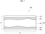
- FIG. 1 is a schematic sectional view of an exemplary configuration of an all-solid-state battery according to the present disclosure.
- any numerical range described using the expression "from * to” represents a range in which numerical values described before and after the "to” are included in the range as a minimum value and a maximum value, respectively.
- an upper limit value or a lower limit value described in one numerical range may be replaced with an upper limit value or a lower limit value in another numerical range described in stages.
- the upper limit value or the lower limit value in the numerical range may be replaced with a value shown in the Examples.
- step includes not only an independent step which is distinguishable from another step, but also a step which is not clearly distinguishable from another step, as long as the purpose of the step is achieved.
- the amount of the component refers to a total amount of the plural kinds of substances, unless otherwise specified.
- the method of producing an all-solid-state battery according to the present disclosure includes:
- first exterior member and a second exterior member may be collectively referred to as an exterior member, and a first resin layer and a second resin layer may be collectively referred to as a resin layer.
- the application of pressure to the structure is preferably performed with an object that is flat at a surface facing the structure.
- Examples of the object that is flat at a surface facing the structure includes a flat panel, a roll, and a table having a flat surface.
- the conditions for the application of pressure to the structure are not particularly limited, and may be selected depending on the purpose or performance of an all-state-battery to be produced.
- the pressure for the pressurization is preferably 0.0001 MPa or more, more preferably 0.001 MPa or more, further preferably 0.01 MPa or more.
- the pressure for the pressurization is preferably 100 MPa or less, more preferably 10 MPa or less, further preferably 1 MPa or less.
- the pressure for the pressurization is preferably from 0.0001 MPa to 100 MPa, more preferably from 0.001 MPa to 10 MPa, further preferably from 0.01 MPa to 1 MPa.
- the number of times for the pressurization may be one or more than one.
- a second pressurization it is possible to perform, in addition to the pressurization that is performed at a temperature at which the resin layer melts or softens (hereinafter, also referred to as a first pressurization), a second pressurization.
- the second pressurization may be performed either before the first pressurization or after the first pressurization.
- the second pressurization may be performed by the same method as the first pressurization, or may be performed by a different method from the first pressurization. From the viewpoint of equalizing a degree of compression in the cell laminate, the second pressurization is preferably performed by applying isotropic pressure to the structure.
- the method for applying isotropic pressure to the structure is not particularly limited.
- the application of isotropic pressure may be performed by a known method using a fluid in a state of liquid, gas or powder as a pressurization medium.
- the method according to the present disclosure may include a process other than the pressurization.
- the method may include a process of enclosing the cell laminate in the exterior members by bonding the peripheries of the first exterior member and the second exterior member.
- the bonding may be performed at the same time as the pressurization.
- the all-solid-state battery according to the first embodiment of the present disclosure includes, in the following order, a first exterior member, a first resin layer, a cell laminate, a second resin layer, and a second exterior member, and at least one of the resin layer or the second resin layer is bonded to the cell laminate.
- Each of the first resin layer and the second layer may be bonded to the cell laminate.
- the all-solid-state battery according to the second embodiment of the present disclosure includes, in the following order, a first exterior member, a first resin layer, a cell laminate, a second resin layer, and a second exterior member, and a variation in thickness in an in-plane-direction of an entire body of the structure is less than a variation in thickness in an in-plane-direction of the cell laminate.
- the all-solid-state battery according to the first embodiment and the all-solid-state battery according to the second embodiment may be collectively referred to as the "all-solid-state battery according to the present disclosure”.
- the all-solid-state battery according to the present disclosure has a resin layer that is disposed between the cell laminate and the exterior member.
- the resin layer functions to absorb variation in thickness in an in-plane direction of the cell laminate. As a result, when pressure is applied to the all-solid-state battery in a thickness direction, it is possible to suppress variation in a degree of compression in an in-plane direction of the all-solid-state battery.
- Fig. 1 is a schematic sectional view illustrating an exemplary configuration of the all-solid-state battery according to the present disclosure.
- the all-solid-state battery 100 shown in Fig. 1 has a structure 60 that includes a first exterior member 10, a first resin layer 20, a cell laminate 30, a second resin layer 40, and a second exterior member 50, in this order.
- the cell laminate 30 has a thickness that is not even in an in-plane direction (a direction indicated by an arrow X).
- the first resin layer 10 and the second resin layer 40 are deformed at a surface facing the cell laminate 30 according to the irregularities at a surface of the cell laminate 30.
- the variation in thickness of the cell laminate 30 is absorbed by the first resin layer 10 and the second resin layer 40. Therefore, when pressure is applied to the all-solid-state battery 100 in a thickness direction (a direction indicated by an arrow Y), it is possible to reduce a difference between the pressure applied at a portion with a smaller thickness of the cell laminate 30 and the pressure applied at a portion with a greater thickness of the cell laminate 30. As a result, a degree of compression is less likely to vary in an in-plane direction of the cell laminate 30.
- the structure 60 in the all-solid-state battery 100 shown in Fig. 1 consists only of a first exterior member 10, a first resin layer 20, a cell laminate 30, a second resin layer 40, and a second exterior member 50
- the configuration of the all-solid-state battery according to the present disclosure is not restricted thereto and may include a layer other than these layers.
- the all-solid-state battery 100 shown in Fig. 1 may include a member that is not illustrated, such as a tab lead.
- the first exterior member 10 and the second exterior member 50 may be formed of plural members.
- the first exterior member 10 and the second exterior member 50 may be formed of a substrate layer and a barrier layer.
- the method for comparing the variation in thickness of the structure of the all-solid-state battery and the variation in thickness of the cell laminate is not particularly limited, and may be performed by a known method.
- the comparison may be based on a difference between a maximum value and a minimum value of the thickness measured at plural portions (preferably at least 5 portions); or may be based on a value of 6 ⁇ obtained from the standard deviation ⁇ as an index for the thickness variation.
- the 6 ⁇ refers to a range in which 99.7% of the measured value is included, provided that the thickness variation complies with a normal distribution.
- a difference between a maximum value and a minimum value in thickness is preferably used as an index for the thickness variation.
- a value of 6 ⁇ is preferably used as an index for the thickness variation.
- the comparison may be based on the length of a profile line A, measured at a portion corresponding to the structure, and the length of a profile line B, measured at a portion corresponding to the cell structure.
- the length of the profile lines may be measured from those obtained in an image of a section of the all-solid-state battery.
- a state in which "a resin layer is bonded to a cell laminate” refers to a state in which a resin layer is fixed to a cell laminate while being in close contact with a cell laminate.
- the resin layer is preferably bonded to each of the cell laminate and the exterior member.
- the resin layer is preferably flat at a surface being in contact with the exterior member.
- the cell laminate include at least one unit cell.
- the constituent elements for the unit cell are not particularly limited, and may be selected from known constituent elements used in all-solid-state batteries.
- the unit cell included in the cell laminate may include a negative electrode layer, a solid electrolyte layer, and a positive electrode layer.
- the negative electrode layer at least includes a negative electrode active material
- the positive electrode layer at least includes a positive electrode active material
- the solid electrolyte layer includes a solid electrolyte
- the negative electrode layer and the positive electrode layer may further include a solid electrolyte.
- the negative electrode active material may be selected from materials having an ability to store or release metal ions, such as lithium ions.
- Examples of the negative electrode active material include metallic lithium, lithium alloy, carbon materials such as graphite and hard carbon, metal alloy, silicon materials such as silicon alloy and Li 4 Ti 5 O 12 (LTO).
- solid electrolyte examples include sulfide-based amorphous solid electrolyte, oxide-based amorphous solid electrolyte, sulfide-based crystalline solid electrolyte, oxide-based crystalline solid electrolyte, iodine-based crystalline solid electrolyte, and nitride-based solid electrolyte.
- Examples of the sulfide-based amorphous electrolyte include Li 2 S-P 2 S 5 , Li 2 O-Li 2 S-P 2 S 5 , Li 2 S, P 2 S 5 , Li 2 S-SiS 2 , LiI-Li 2 S-SiS 2 , LiI-Li 2 S-P 2 S 5 , LiI-Li 2 S-P 2 O 5 , LiI-LiBr-Li 2 S-P 2 S 5 and LiI-Li 3 PO 4 -P 2 S 5 .
- oxide-based amorphous electrolyte examples include Li 2 O-B 2 O 3 -P 2 O 5 and Li 2 O-SiO 2 .
- oxide-based crystalline electrolyte examples include Li 5 La 3 Ta 2 O 12 , Li 7 Zr 2 O 12 , Li 6 BaLa 2 Ta 2 O 12 and Li 3 PO ( 4-3 / 2w )N w (w ⁇ 1).
- the materials having an argyrodite-type crystal structure may be referred to as argyrodite-type sulfide-based solid electrolytes.
- Examples of the iodine-based crystalline solid electrolyte include LiI.
- nitride-based solid electrolyte examples include Li 3 N.
- argyrodite-type sulfide-based solid electrolytes are preferred.
- Examples of the positive electrode active material include metal oxides including lithium and a transition metal such as manganese, cobalt, nickel and titanium.
- metal oxides include lithium cobalt oxide, lithium nickel oxide, lithium manganese oxide, lithium nickel-cobalt-manganese oxide (NCM), Li-Mn oxide spinel substituted with a different element, lithium titanium oxide, and lithium metal phosphate such as lithium iron phosphate.
- the negative electrode layer may be formed of a negative electrode active material layer and a negative electrode current collector.
- the positive electrode layer may be formed of a positive electrode active material layer and a positive electrode current collector.
- Examples of the material for the negative electrode current collector or the positive electrode current collector include metals such as Ag, Cu, Au, Al, Ni, Fe and Ti and alloys including these metals.
- the material for the negative electrode current collector is preferably Cu or Ni.
- Ni is preferred from the viewpoint of avoiding the sulfidation of the negative electrode current collector.
- the material for the positive electrode current collector is preferably Al.
- the negative electrode layer formed of a negative electrode active material and a negative electrode current collector may be obtained by, for example, applying a negative electrode composition, including a negative electrode active material and a binder, onto a surface of the negative electrode current collector, and drying the composition.
- the negative electrode active material layer may be formed at one side of the negative electrode current collector, or may be formed at both sides of the negative electrode current collector.
- the negative electrode composition may include a solvent for the binder, a conductive material, or the like.
- Examples of the method for forming a solid electrolyte layer include a method of performing compression molding to a material including a solid electrode that is in a state of powder or pellets; and a method of applying a material including a solid electrode that is in a state of a paste, onto a base plate, and then drying the same.
- the positive electrode layer formed of a positive electrode active material and a positive electrode current collector may be obtained by, for example, applying a positive electrode composition including a positive electrode active material and a binder, onto a surface of the positive electrode current collector, and drying the composition.
- the positive electrode active material layer may be formed at one side of the positive electrode current collector, or may be formed at both sides of the positive electrode current collector.
- the positive electrode composition may include a solvent for the binder, a conductive material, or the like.
- the thickness of the cell laminate is not particularly limited, and may be adjusted depending on the purpose or performance of an all-solid-state battery.
- the thickness of the cell laminate may be selected from a range of from 0.1 mm to 20 mm, from 0.5 to 10 mm, or from 1 mm to 5 mm.
- the resin layer preferably has an ability to be bonded to the cell laminate.
- Examples of the resin layer having an ability to be bonded to the cell laminate include a layer that includes a resin that melts or softens by heating.
- thermoplastic resins examples include polyolefin such as polyethylene and polypropylene, polyamide, polyester such as polyethylene terephthalate, polyurethane, and ethylene-vinyl acetate copolymer.
- the thickness of the resin layer is preferably 10 ⁇ m or more, more preferably 10 ⁇ m or more, further preferably 10 ⁇ m or more.
- the thickness of the resin layer may be 500 ⁇ m or less.
- the resin layer may be integrated with the exterior member, or may not be integrated with the exterior member. From the viewpoint of readily performing a process for producing an all-solid-state battery, the resin layer is preferably integrated with the exterior member.
- the material for the exterior member is not particularly limited, and may be determined depending on the purpose or performance of an all-solid-state battery.
- the exterior member may include a substrate layer and a barrier layer.
- the material for the substrate layer is not particularly limited, and may be resin, metal or the like.
- the resin include thermoplastic resins as mentioned above, preferably thermoplastic resins that does not melt or soften at a temperature at which a resin included in the resin layer melts or softens.
- Examples of the metal include aluminum, aluminum alloy, copper, copper alloy, stainless steel, and nickel.
- barrier layer examples include a metal layer and a deposited layer formed by vapor deposition.
- the configuration of the all-solid-state battery according to the present disclosure is not particularly limited.
- the all-solid-state battery according to the present disclosure preferably has a laminate-type configuration.
- the thickness of the all-solid-state battery is not particularly limited, and may be determined depending on the purpose or performance of the all-solid-state battery.
- the thickness of the all-solid-state battery may be selected from a range of from 0.2 mm to 21 mm, from 0.5 to 10 mm, or from 1 mm to 5 mm.
- a slurry was prepared in which a positive electrode active material with a molar composition of LiNi 0.5 Co 0.2 Mn 0.3 O 2 , an argyrodite-type sulfide-based solid electrolyte, a conductive material and a binder are dispersed in a solvent.
- the slurry was applied at each side of an aluminum foil as a current collector and dried, thereby obtaining a positive electrode layer having a configuration in which a positive electrode active material layer with a thickness of approximately 100 ⁇ m was formed at each side of the positive electrode current collector (positive electrode active material layer/positive electrode current collector/positive electrode active material layer).
- a slurry was prepared by dispersing graphite as a negative electrode active material, an argyrodite-type sulfide-based solid electrolyte, and a binder, in a solvent.
- the slurry was applied at each side of a copper foil as a current collector and dried, thereby obtaining a negative electrode layer having a configuration in which a negative electrode active material layer with a thickness of approximately 200 ⁇ m was disposed at each side of the current collector.
- a slurry was prepared by dispersing an argyrodite-type sulfide-based solid electrolyte and a binder, in a solvent. The slurry was applied at one side of a metal foil and dried, thereby obtaining a solid electrolyte sheet having a configuration in which a solid-electrolyte layer with a thickness of approximately 30 ⁇ m was disposed at one side of the metal foil.
- a laminate was obtained by disposing the solid-electrolyte sheet at each side of the negative electrode layer, such that the solid-electrolyte layer is in contact with the negative electrode active material layer.
- the laminate was subjected to roll pressing and the metal foil was removed from the laminate, thereby obtaining a negative electrode layer with a solid electrolyte layer transferred to each side thereof (solid electrolyte layer/negative electrode active material layer/negative electrode current collector/negative electrode active material layer/solid electrolyte layer).
- a cell laminate with a thickness of 2 mm was prepared by cutting a negative electrode layer and a positive electrode layer into a predetermined size, and disposing the same in an alternate manner.
- the cell laminate was sandwiched by an external member integrated with a resin layer (resin layer made of polypropylene/barrier layer made of aluminum/substrate layer made of polyethylene terephthalate).
- a resin layer made of polypropylene/barrier layer made of aluminum/substrate layer made of polyethylene terephthalate.
- WIP warm isostatic pressing
- the external member was removed from the cell laminate after the WIP, and a tab lead was attached to a tab of the cell laminate, i.e., a portion of a current collector at which an electrode layer was not formed. Subsequently, the cell laminate was sandwiched by an external member having the same configuration as described above. The periphery of the cell laminate was vacuum-sealed, thereby obtaining a structure. The structure was sandwiched by flat panels heated at 180°C, and pressure was applied to the structure, whereby an all-solid-state battery having a thickness of 2.5 mm was obtained.
- the all-solid-state battery was cut in a thickness direction, and a section thereof was observed.
- the resin layers made of polypropylene were bonded to the cell laminate.
- the resin layers were deformed according to the irregularities at a surface of the cell laminate, and the variation in thickness in an in-plane direction of the cell laminate was absorbed by the resin layers.
- the variation in thickness in an in-plane direction of an entire body of the all-solid-state battery was smaller than the variation in thickness in an in-plane direction of the cell laminate.
Landscapes
- Chemical & Material Sciences (AREA)
- General Chemical & Material Sciences (AREA)
- Chemical Kinetics & Catalysis (AREA)
- Electrochemistry (AREA)
- Engineering & Computer Science (AREA)
- Manufacturing & Machinery (AREA)
- Inorganic Chemistry (AREA)
- General Physics & Mathematics (AREA)
- Condensed Matter Physics & Semiconductors (AREA)
- Physics & Mathematics (AREA)
- Materials Engineering (AREA)
- Secondary Cells (AREA)
- Sealing Battery Cases Or Jackets (AREA)
Applications Claiming Priority (1)
| Application Number | Priority Date | Filing Date | Title |
|---|---|---|---|
| JP2023075860A JP7768190B2 (ja) | 2023-05-01 | 2023-05-01 | 全固体電池の製造方法及び全固体電池 |
Publications (2)
| Publication Number | Publication Date |
|---|---|
| EP4459729A2 true EP4459729A2 (de) | 2024-11-06 |
| EP4459729A3 EP4459729A3 (de) | 2025-01-22 |
Family
ID=90365245
Family Applications (1)
| Application Number | Title | Priority Date | Filing Date |
|---|---|---|---|
| EP24163297.5A Pending EP4459729A3 (de) | 2023-05-01 | 2024-03-13 | Verfahren zur herstellung einer festkörperbatterie und festkörperbatterie |
Country Status (5)
| Country | Link |
|---|---|
| US (1) | US20240372181A1 (de) |
| EP (1) | EP4459729A3 (de) |
| JP (1) | JP7768190B2 (de) |
| KR (1) | KR102941552B1 (de) |
| CN (1) | CN118888862A (de) |
Citations (1)
| Publication number | Priority date | Publication date | Assignee | Title |
|---|---|---|---|---|
| JP2021177448A (ja) | 2020-05-07 | 2021-11-11 | 三星エスディアイ株式会社Samsung SDI Co., Ltd. | 全固体二次電池 |
Family Cites Families (9)
| Publication number | Priority date | Publication date | Assignee | Title |
|---|---|---|---|---|
| JP2006120577A (ja) * | 2004-10-25 | 2006-05-11 | Nissan Motor Co Ltd | ポリマー電池 |
| CN102598391A (zh) | 2009-11-02 | 2012-07-18 | 丰田自动车株式会社 | 固体电解质电池的制造方法 |
| JPWO2012164723A1 (ja) * | 2011-06-02 | 2014-07-31 | トヨタ自動車株式会社 | 全固体電池の製造方法 |
| JP2014120456A (ja) * | 2012-12-19 | 2014-06-30 | Nissan Motor Co Ltd | 二次電池 |
| EP3518316A4 (de) * | 2016-11-24 | 2020-06-03 | Murata Manufacturing Co., Ltd. | Zelle und elektronische vorrichtung |
| JP2020064742A (ja) * | 2018-10-16 | 2020-04-23 | 昭和電工株式会社 | 充電池パック、充電池パックの製造方法 |
| JP7151942B1 (ja) | 2020-12-02 | 2022-10-12 | 大日本印刷株式会社 | 全固体電池の製造に用いられる工程フィルム、及び全固体電池の製造方法 |
| JP7484809B2 (ja) * | 2021-05-13 | 2024-05-16 | トヨタ自動車株式会社 | 全固体電池 |
| US20240283060A1 (en) * | 2021-06-17 | 2024-08-22 | Vehicle Energy Japan Inc. | Solid electrolyte battery, manufacturing method for solid electrolyte battery, and transportation apparatus |
-
2023
- 2023-05-01 JP JP2023075860A patent/JP7768190B2/ja active Active
-
2024
- 2024-03-13 EP EP24163297.5A patent/EP4459729A3/de active Pending
- 2024-03-25 US US18/614,938 patent/US20240372181A1/en active Pending
- 2024-04-12 KR KR1020240049145A patent/KR102941552B1/ko active Active
- 2024-04-23 CN CN202410489502.9A patent/CN118888862A/zh active Pending
Patent Citations (1)
| Publication number | Priority date | Publication date | Assignee | Title |
|---|---|---|---|---|
| JP2021177448A (ja) | 2020-05-07 | 2021-11-11 | 三星エスディアイ株式会社Samsung SDI Co., Ltd. | 全固体二次電池 |
Also Published As
| Publication number | Publication date |
|---|---|
| EP4459729A3 (de) | 2025-01-22 |
| JP2024160640A (ja) | 2024-11-14 |
| JP7768190B2 (ja) | 2025-11-12 |
| US20240372181A1 (en) | 2024-11-07 |
| KR102941552B1 (ko) | 2026-03-19 |
| CN118888862A (zh) | 2024-11-01 |
| KR20240160012A (ko) | 2024-11-08 |
Similar Documents
| Publication | Publication Date | Title |
|---|---|---|
| KR102532604B1 (ko) | 전고체 이차전지, 적층 전고체 이차전지 및 전고체 이차전지의 제조방법 | |
| JP5144846B2 (ja) | グリーンシート積層体の製造方法 | |
| JP6943023B2 (ja) | 積層体グリーンシート、全固体二次電池およびその製造方法 | |
| WO2018025594A1 (ja) | 全固体リチウム電池 | |
| JP7183529B2 (ja) | 積層体グリーンシート、全固体二次電池及びその製造方法 | |
| WO2018025595A1 (ja) | 全固体リチウム電池の使用方法 | |
| JP2018063850A (ja) | 積層体グリーンシート、全固体二次電池及びその製造方法 | |
| JP2017152147A (ja) | 複合活物質二次粒子、積層体グリーンシート、全固体二次電池及びそれらの製造方法 | |
| WO2014170998A1 (ja) | 全固体リチウムイオン二次電池 | |
| JP2017054792A (ja) | リチウム電池 | |
| WO2017146133A1 (ja) | 積層体グリーンシート、連続積層体グリーンシート、積層焼成体、連続積層焼成体及び全固体二次電池、並びに積層体グリーンシートの製造方法、連続積層体グリーンシートの製造方法及び全固体二次電池の製造方法 | |
| JP7280379B2 (ja) | リチウム二次電池及びその充電状態の測定方法 | |
| JPWO2017065034A1 (ja) | 全固体リチウム電池の製造方法 | |
| KR20170023298A (ko) | 전고체 이차 전지 및 그 제조방법 | |
| EP3796455B1 (de) | Lithiumsekundärbatterie | |
| JP7022207B2 (ja) | リチウム二次電池 | |
| EP4459729A2 (de) | Verfahren zur herstellung einer festkörperbatterie und festkörperbatterie | |
| EP3961753B1 (de) | Lithiumsekundärbatterie | |
| JP7104148B2 (ja) | リチウム二次電池 | |
| EP3796457B1 (de) | Lithiumsekundärbatterie | |
| EP3796456B1 (de) | Lithiumsekundärbatterie | |
| CN111902991B (zh) | 锂二次电池及内置电池的卡片 | |
| TW202027321A (zh) | 鋰二次電池 | |
| JP7193622B2 (ja) | リチウム二次電池 | |
| TW202339329A (zh) | 多孔電極、包含該電極的電池、電子及電化學裝置、以及其製造方法 |
Legal Events
| Date | Code | Title | Description |
|---|---|---|---|
| PUAI | Public reference made under article 153(3) epc to a published international application that has entered the european phase |
Free format text: ORIGINAL CODE: 0009012 |
|
| STAA | Information on the status of an ep patent application or granted ep patent |
Free format text: STATUS: REQUEST FOR EXAMINATION WAS MADE |
|
| 17P | Request for examination filed |
Effective date: 20240313 |
|
| AK | Designated contracting states |
Kind code of ref document: A2 Designated state(s): AL AT BE BG CH CY CZ DE DK EE ES FI FR GB GR HR HU IE IS IT LI LT LU LV MC ME MK MT NL NO PL PT RO RS SE SI SK SM TR |
|
| PUAL | Search report despatched |
Free format text: ORIGINAL CODE: 0009013 |
|
| AK | Designated contracting states |
Kind code of ref document: A3 Designated state(s): AL AT BE BG CH CY CZ DE DK EE ES FI FR GB GR HR HU IE IS IT LI LT LU LV MC ME MK MT NL NO PL PT RO RS SE SI SK SM TR |
|
| RIC1 | Information provided on ipc code assigned before grant |
Ipc: H01M 10/12 20060101ALI20241216BHEP Ipc: H01M 10/0562 20100101ALI20241216BHEP Ipc: H01M 50/133 20210101ALI20241216BHEP Ipc: H01M 50/124 20210101ALI20241216BHEP Ipc: H01M 50/121 20210101ALI20241216BHEP Ipc: H01M 50/105 20210101ALI20241216BHEP Ipc: H01M 10/0585 20100101ALI20241216BHEP Ipc: H01M 10/0525 20100101AFI20241216BHEP |