EP4459415A2 - Überschwingfreie schnellstart-bandlückenreferenzschaltung, chip und elektronische vorrichtung - Google Patents
Überschwingfreie schnellstart-bandlückenreferenzschaltung, chip und elektronische vorrichtung Download PDFInfo
- Publication number
- EP4459415A2 EP4459415A2 EP22914504.0A EP22914504A EP4459415A2 EP 4459415 A2 EP4459415 A2 EP 4459415A2 EP 22914504 A EP22914504 A EP 22914504A EP 4459415 A2 EP4459415 A2 EP 4459415A2
- Authority
- EP
- European Patent Office
- Prior art keywords
- pmos transistor
- current
- circuit
- transistor
- bias current
- Prior art date
- Legal status (The legal status is an assumption and is not a legal conclusion. Google has not performed a legal analysis and makes no representation as to the accuracy of the status listed.)
- Pending
Links
Images


Classifications
-
- G—PHYSICS
- G05—CONTROLLING; REGULATING
- G05F—SYSTEMS FOR REGULATING ELECTRIC OR MAGNETIC VARIABLES
- G05F3/00—Non-retroactive systems for regulating electric variables by using an uncontrolled element, or an uncontrolled combination of elements, such element or such combination having self-regulating properties
- G05F3/02—Regulating voltage or current
- G05F3/08—Regulating voltage or current wherein the variable is DC
- G05F3/10—Regulating voltage or current wherein the variable is DC using uncontrolled devices with non-linear characteristics
- G05F3/16—Regulating voltage or current wherein the variable is DC using uncontrolled devices with non-linear characteristics being semiconductor devices
- G05F3/20—Regulating voltage or current wherein the variable is DC using uncontrolled devices with non-linear characteristics being semiconductor devices using diode- transistor combinations
- G05F3/26—Current mirrors
- G05F3/262—Current mirrors using field-effect transistors only
-
- G—PHYSICS
- G05—CONTROLLING; REGULATING
- G05F—SYSTEMS FOR REGULATING ELECTRIC OR MAGNETIC VARIABLES
- G05F1/00—Automatic systems in which deviations of an electric quantity from one or more predetermined values are detected at the output of the system and fed back to a device within the system to restore the detected quantity to its predetermined value or values, i.e. retroactive systems
- G05F1/10—Regulating voltage or current
- G05F1/46—Regulating voltage or current wherein the variable actually regulated by the final control device is DC
- G05F1/468—Regulating voltage or current wherein the variable actually regulated by the final control device is DC characterised by reference voltage circuitry, e.g. soft start, remote shutdown
-
- G—PHYSICS
- G05—CONTROLLING; REGULATING
- G05F—SYSTEMS FOR REGULATING ELECTRIC OR MAGNETIC VARIABLES
- G05F1/00—Automatic systems in which deviations of an electric quantity from one or more predetermined values are detected at the output of the system and fed back to a device within the system to restore the detected quantity to its predetermined value or values, i.e. retroactive systems
- G05F1/10—Regulating voltage or current
- G05F1/46—Regulating voltage or current wherein the variable actually regulated by the final control device is DC
- G05F1/56—Regulating voltage or current wherein the variable actually regulated by the final control device is DC using semiconductor devices in series with the load as final control devices
- G05F1/575—Regulating voltage or current wherein the variable actually regulated by the final control device is DC using semiconductor devices in series with the load as final control devices characterised by the feedback circuit
-
- G—PHYSICS
- G05—CONTROLLING; REGULATING
- G05F—SYSTEMS FOR REGULATING ELECTRIC OR MAGNETIC VARIABLES
- G05F3/00—Non-retroactive systems for regulating electric variables by using an uncontrolled element, or an uncontrolled combination of elements, such element or such combination having self-regulating properties
- G05F3/02—Regulating voltage or current
- G05F3/08—Regulating voltage or current wherein the variable is DC
- G05F3/10—Regulating voltage or current wherein the variable is DC using uncontrolled devices with non-linear characteristics
- G05F3/16—Regulating voltage or current wherein the variable is DC using uncontrolled devices with non-linear characteristics being semiconductor devices
- G05F3/20—Regulating voltage or current wherein the variable is DC using uncontrolled devices with non-linear characteristics being semiconductor devices using diode- transistor combinations
- G05F3/30—Regulators using the difference between the base-emitter voltages of two bipolar transistors operating at different current densities
Definitions
- the present invention relates to a overshoot-free fast start-up bandgap reference circuit, and also relates to an integrated circuit chip and a corresponding electronic device that include the overshoot-free fast start-up bandgap reference circuit, and relates to the field of analog integrated circuit technologies.
- an electronic device With the continuous development of an integrated circuit technology, an electronic device increasingly needs low power consumption and low latency performance.
- each circuit module in an entire system When the electronic device is in an idle state, each circuit module in an entire system is in a cut-off state, so that standby power consumption is effectively reduced.
- an enable signal comes, each circuit module in the entire system can quickly start to enter a normal operating state. Therefore, the electronic device has increasingly high requirements on a startup process.
- startup time of a bandgap reference circuit greatly influences a startup speed of the entire system.
- a primary technical problem to be resolved by the present invention is to provide a overshoot-free fast start-up bandgap reference circuit (bandgap reference circuit for short).
- the bandgap reference circuit implements a overshoot-free fast start-up under all PVT (process, power supply voltage, and temperature) conditions.
- Another technical problem to be resolved by the present invention is to provide an integrated circuit chip and a corresponding electronic device that include the overshoot-free fast start-up bandgap reference circuit.
- a overshoot-free fast start-up bandgap reference circuit including a bias current generation unit 101 and a reference core unit 102.
- An output end of the bias current generation unit 101 is connected to an input end of the reference core unit 102.
- the bias current generation unit 101 generates a bias current that is not related to a power supply voltage and has a zero temperature coefficient, used as an input signal of the reference core unit 102.
- the reference core unit 102 generates a pre-charge current based on the bias current, and implements a overshoot-free fast start-up in a pre-charge manner.
- the bias current generation unit 101 includes a first starting circuit 201 and a bias current generation circuit 202.
- An output end of the first starting circuit 201 is connected to an input end of the bias current generation circuit 202.
- the first starting circuit 201 includes a starting current generation branch 301, a proportional mirror and injection branch 302, and a feedback current cut-off control branch 303.
- the starting current generation branch 301 generates a starting current
- the proportional mirror and injection branch 302 proportionally mirrors the starting current and injects the starting current into the bias current generation circuit 202.
- the feedback current cut-off control branch 303 finally reduces the proportionally mirrored and injected current to zero by using feedback current cut-off control.
- the bias current generation circuit 202 includes a third NMOS transistor MN3, a fourth NMOS transistor MN4, a fifth NMOS transistor MN5, a sixth NMOS transistor MN6, a first PMOS transistor MP1, a second PMOS transistor MP2, a third PMOS transistor MP3, a fourth PMOS transistor MP4, a fifth PMOS transistor MP5, a sixth PMOS transistor MP6, and a thirteenth PMOS transistor MP13.
- the third NMOS transistor MN3, the fourth NMOS transistor MN4, the fifth NMOS transistor MN5, and the sixth NMOS transistor MN6 form NMOS current proportional mirror pair transistors in a cascode structure.
- the third PMOS transistor MP3, the fourth PMOS transistor MP4, the fifth PMOS transistor MP5, and the sixth PMOS transistor MP6 form PMOS current proportional mirror pair transistors in a cascode structure.
- the first PMOS transistor MP1, the second PMOS transistor MP2, the third PMOS transistor MP3, and the fourth PMOS transistor MP4 form PMOS current proportional mirror pair transistors in a cascode structure.
- the bias current generation circuit 202 further includes a first resistor R1, a second resistor R2, and a third resistor R3.
- An end of the first resistor R1 is connected to a source of the third PMOS transistor MP3, and the other end of the first resistor R1 is connected to a power supply end.
- An end of the second resistor R2 is connected to a drain of the fifth NMOS transistor MN5, and the other end of the second resistor R2 is separately connected to a drain of the sixth PMOS transistor MP6 and a gate of the fifth PMOS transistor MP5.
- An end of the third resistor R3 is separately connected to a drain of the sixth NMOS transistor MN6 and a gate of the fourth NMOS transistor MN4, and the other end is separately connected to a gate of the sixth NMOS transistor MN6 and a drain of the fourth PMOS transistor MP4.
- the first resistor R1, the second resistor R2, and the third resistor R3 each have different temperature coefficients.
- the reference core unit 102 includes a second starting circuit 401 and a reference core circuit 402. An output end of the second starting circuit 401 is connected to an input end of the reference core circuit 402.
- the second starting circuit 401 includes a bias current injection branch 501, a proportional mirror and injection branch 502, and a feedback current cut-off control branch 503.
- the bias current injection branch 501 receives the bias current output by the bias current generation unit 101.
- the proportional mirror and injection branch 502 proportionally mirrors the bias current to form a pre-charge current and injects the pre-charge current into the reference core circuit 402.
- the feedback current cut-off control branch 503 reduces the pre-charge current to zero after the reference core circuit 402 is started.
- the pre-charge current is divided into three currents.
- a first pre-charge current is a drain output current of a thirty-third PMOS transistor MP13, and is injected into an output end of the reference core circuit 402.
- a second pre-charge current is a drain output current of a thirty-fourth PMOS transistor MP14, and is injected into a non-inverting input end of a first operational amplifier in the reference core circuit 402.
- a third pre-charge current is a drain output current of a thirty-fifth PMOS transistor MP15, and is injected into an inverting input end of the first operational amplifier in the reference core circuit 402.
- the feedback current cut-off control branch 503 includes a twenty-second NMOS transistor MN2, a thirty-first PMOS transistor MP11, and a thirty-second PMOS transistor MP12.
- a drain of the twenty-second NMOS transistor MN2 is connected to a drain of the thirty-first PMOS transistor MP11 as well as a gate and a drain of the thirty-second PMOS transistor MP12.
- a source of the thirty-first PMOS transistor MP11 is connected to a power supply end.
- a gate of the thirty-first PMOS transistor MP11 is connected to an output end of a first operational amplifier in the reference core circuit 402.
- a current on the thirty-first PMOS transistor MP11 is greater than a current on the twenty-second NMOS transistor (MN2).
- a gate voltage of the thirty-second PMOS transistor MP12 is increased to VDD.
- the pre-charge current is reduced to zero.
- an integrated circuit chip including the foregoing overshoot-free fast start-up bandgap reference circuit.
- an electronic device including the foregoing overshoot-free fast start-up bandgap reference circuit.
- the overshoot-free fast start-up bandgap reference circuit implemented in the present invention implements a characteristic that the bias current is not related to a power supply voltage and has a zero-temperature coefficient by using a self-biased cascode current mirror structure and resistors with different temperature coefficient types.
- an establishment process of a loop bias point voltage and an output voltage of an operational amplifier is accelerated in a pre-charge manner, so that a overshoot-free fast start-up of the bandgap reference circuit can be implemented under all PVT (process, power supply voltage, and temperature) conditions, enabling the electronic device to have low power consumption and low latency performance.
- PVT process, power supply voltage, and temperature
- a overshoot-free fast start-up bandgap reference circuit 100 provided in an embodiment of the present invention includes a bias current generation unit 101 and a reference core unit 102. An output end of the bias current generation unit 101 is connected to an input end of the reference core unit 102.
- the bias current generation unit 101 generates a bias current I BIAS that is not related to a power supply voltage and has a zero-temperature coefficient, used as an input signal of the reference core unit 102.
- the reference core unit 102 generates a pre-charge current and a current required for an operation of an operational amplifier based on the input bias current I BIAS , and implements a overshoot-free fast start-up in a pre-charge manner.
- bias current generation unit 101 and reference core unit 102 A circuit structure and an operating principle of the bias current generation unit 101 and reference core unit 102 are described in detail below.
- the bias current generation unit 101 includes a first starting circuit 201 and a bias current generation circuit 202.
- An output end of the first starting circuit 201 is connected to an input end of the bias current generation circuit 202.
- the bias current generation circuit 202 generates a bias current I BIAS that is not related to a power supply voltage and has a zero temperature coefficient, and the bias current I BIAS is an input signal of the reference core unit 102.
- the first starting circuit 201 includes a starting current generation branch 301, a proportional mirror and injection branch 302, and a feedback current cut-off control branch 303.
- the starting current generation branch 301 generates a starting current.
- the proportional mirror and injection branch 302 proportionally mirrors the starting current and injects the starting current into the bias current generation circuit 202.
- the feedback current cut-off control branch 303 finally reduces the proportionally mirrored and injected current to zero by using feedback current cut-off control.
- the starting current generation branch 301 includes an eleventh PMOS transistor MP11, a twelfth PMOS transistor MP12, a first NMOS transistor MN1, and a first switch transistor.
- the first switch transistor receives an input by an enable signal.
- An end of the first switch transistor is connected to a drain of the twelfth PMOS transistor MP12, and the drain and a gate of the twelfth PMOS transistor MP12 are short-circuited.
- a source of the twelfth PMOS transistor MP12 is connected to a drain of the eleventh PMOS transistor MP11, the drain and a gate of the eleventh PMOS transistor MP11 are short-circuited, and a source of the eleventh PMOS transistor MP11 is connected to a power supply end VDD.
- the other end of the first switch transistor is connected to a drain of the first NMOS transistor MN1, the drain and a gate of the first NMOS transistor MN1 are short-circuited, and a source of the first NMOS transistor MN1 is connected to a common ground end VSS.
- EN VDD
- the first switch transistor turns on, a branch where the first switch transistor is located generates a starting current, and the starting current is input to the proportional mirror and injection branch 302.
- the proportional mirror and injection branch 302 includes a first NMOS transistor MN1, a second NMOS transistor MN2, an eighth PMOS transistor MP8, a ninth PMOS transistor MP9, and a tenth PMOS transistor MP10.
- the first NMOS transistor MN1 and the second NMOS transistor MN2 form NMOS current proportional mirror pair transistors
- the eighth PMOS transistor MP8, the ninth PMOS transistor MP9, and the tenth PMOS transistor MP10 form PMOS current proportional mirror pair transistors.
- a gate of the second NMOS transistor MN2 is connected to a gate of the first NMOS transistor MN1.
- a source of the second NMOS transistor MN2 is connected to the common ground end VSS.
- a drain of the second NMOS transistor MN2 is connected to a gate of the eighth PMOS transistor MP8.
- a source of the eighth PMOS transistor MP8 is connected to the power supply end VDD.
- a drain and the gate of the eighth PMOS transistor MP8 are short-circuited.
- a source of the ninth PMOS transistor MP9 and a source of the tenth PMOS transistor MP10 are separately connected to the power supply end VDD.
- a gate of the ninth PMOS transistor MP9 and a gate of the tenth PMOS transistor MP10 are both connected to the drain of the second NMOS transistor MN2.
- a drain of the ninth PMOS transistor MP9 and a drain of the tenth PMOS transistor MP10 are separately connected to the bias current generation circuit 202.
- the ninth PMOS transistor MP9 and the tenth PMOS transistor MP 10 have no current injected into the bias current generation circuit 202.
- the NMOS current proportional mirror pair transistors (MN1 and MN2) and the PMOS current proportional mirror pair transistors (MP8, MP9, and MP10) proportionally mirror the starting current of the branch where the first switch transistor is located and then inject the starting current into the bias current generation circuit 202 in two currents, so that gate voltages of the fourth NMOS transistor MN4 and the sixth NMOS transistor MN6 increase quickly.
- the feedback current cut-off control branch 303 includes a second NMOS transistor MN2, a seventh PMOS transistor MP7, and an eighth PMOS transistor MP8.
- a source of the seventh PMOS transistor MP7 is connected to the power supply end VDD.
- a drain of the seventh PMOS transistor MP7 is connected to a drain and a gate of the eighth PMOS transistor MP8 as well as a drain of the second NMOS transistor MN2.
- a gate of the seventh PMOS transistor MP7 is connected to the bias current generation circuit 202.
- I MN2 I MP7 + I MP8 .
- a current on the seventh PMOS transistor MP7 is less than a current on the second NMOS transistor MN2, that is, I MP7 ⁇ I MN2 .
- I MP8 is proportionally mirrored to generate two injected currents that are injected into the bias current generation circuit 202.
- a current on the seventh PMOS transistor MP7 is greater than a current on the second NMOS transistor MN2, that is, I MP7 > I MN2 .
- I MP8 0, that is, a proportionally mirrored and injected current is reduced to zero.
- the bias current generation circuit 202 includes a third NMOS transistor MN3, a fourth NMOS transistor MN4, a fifth NMOS transistor MN5, a sixth NMOS transistor MN6, a first PMOS transistor MP1, a second PMOS transistor MP2, a third PMOS transistor MP3, a fourth PMOS transistor MP4, a fifth PMOS transistor MP5, a sixth PMOS transistor MP6, a thirteenth PMOS transistor MP13, a first resistor R1, a second resistor R2, and a third resistor R3.
- the third NMOS transistor MN3, the fourth NMOS transistor MN4, the fifth NMOS transistor MN5, and the sixth NMOS transistor MN6 form NMOS current proportional mirror pair transistors in a cascode structure.
- the third PMOS transistor MP3, the fourth PMOS transistor MP4, the fifth PMOS transistor MP5, and the sixth PMOS transistor MP6 form PMOS current proportional mirror pair transistors in a cascode structure.
- the first PMOS transistor MP1, the second PMOS transistor MP2, the third PMOS transistor MP3, and the fourth PMOS transistor MP4 form PMOS current proportional mirror pair transistors in a cascode structure.
- a gate of the third NMOS transistor MN3 and a gate of the fourth NMOS transistor MN4 are connected and then jointly connected to an output of the proportional mirror and injection branch 302, that is, a drain of the tenth PMOS transistor MP10.
- a source of the third NMOS transistor MN3 and a source of the fourth NMOS transistor MN4 are separately connected to the common ground end VSS.
- a drain of the third NMOS transistor MN3 is connected to a source of the fifth NMOS transistor MN5.
- a drain of the fourth NMOS transistor MN4 is connected to a source of the sixth NMOS transistor MN6.
- a gate of the fifth NMOS transistor MN5 and a gate of the sixth NMOS transistor MN6 are connected and then are jointly connected to another output of the proportional mirror and injection branch 302, that is, a drain of the ninth PMOS transistor MP9.
- a drain of the sixth NMOS transistor MN6 is connected to the gate of the fourth NMOS transistor MN4 and the third resistor R3, and the other end of the third resistor R3 is connected to a gate of the sixth NMOS transistor MN6 and a drain of the fourth PMOS transistor MP4.
- a gate of the fourth PMOS transistor MP4 is connected to a gate of the sixth PMOS transistor MP6 and a gate of the second PMOS transistor MP2.
- a source of the fourth PMOS transistor MP4 is connected to a drain of the third PMOS transistor MP3.
- a gate of the third PMOS transistor MP3 is connected to a gate of the fifth PMOS transistor MP5 and a gate of the first PMOS transistor MP1.
- a source of the third PMOS transistor MP3 is connected to the first resistor R1, and the other end of the first resistor R1 is connected to the power supply end VDD.
- a drain of the fifth NMOS transistor MN5 is connected to the second resistor R2 and the gate of the fourth PMOS transistor MP4, and the other end of the second resistor R2 is separately connected to a drain of the sixth PMOS transistor MP6 and the gate of the fifth PMOS transistor MP5.
- a source of the sixth PMOS transistor MP6 is connected to a drain of the fifth PMOS transistor MP5, and a source of the fifth PMOS transistor MP5 is connected to the power supply end VDD.
- the gate of the fifth PMOS transistor MP5 is connected to a gate of a seventh PMOS transistor MP7 in the feedback current cut-off control branch 303, and the gate of the fifth PMOS transistor MP5 is connected to a drain of the thirteenth PMOS transistor MP13.
- a source of the thirteenth PMOS transistor MP13 is connected to the power supply end VDD, and a gate of the thirteenth PMOS transistor MP13 is connected to an input end EN of an enable signal.
- a source of the first PMOS transistor MP1 is connected to the power supply end VDD, and a drain of the first PMOS transistor MP1 is connected to a source of the second PMOS transistor MP2.
- a drain of the second PMOS transistor MP2 is connected to an input end of the reference core unit 102, to be specifically, the bias current I BIAS is input.
- the thirteenth PMOS transistor MP13 turns on, the gate of the third PMOS transistor MP3 and the gate of the fifth PMOS transistor MP5 are increased to high potential. Therefore, currents of branches where the fifth PMOS transistor MP5 and the sixth PMOS transistor MP6 are located are all zero. In this case, the gate of the fourth NMOS transistor MN4 and the gate of the sixth NMOS transistor MN6 are in a low potential state, and an entire circuit is in a stable zero-current state.
- the thirteenth PMOS transistor MP13 cuts off.
- the proportional mirror and injection branch 302 injects a mirrored and injected current into branches where the fourth NMOS transistor MN4 and the sixth NMOS transistor MN6 are located.
- Current proportional mirror pair transistors in a cascode structure that are the third NMOS transistor MN3, the fourth NMOS transistor MN4, the fifth NMOS transistor MN5, and the sixth NMOS transistor MN6 copy the injected current via proportional mirror, as a result, branches of the fifth PMOS transistor MP5, the sixth PMOS transistor MP6, the second resistor R2, the fifth NMOS transistor MN5, and the third NMOS transistor MN3 generate currents, and gate voltages of the fifth PMOS transistor MP5 and the sixth PMOS transistor MP6 are reduced.
- the current proportional mirror pair transistors in a cascode structure that are the third PMOS transistor MP3, the fourth PMOS transistor MP4, the fifth PMOS transistor MP5, and the sixth PMOS transistor MP6 recopy the currents of branches where the fifth PMOS transistor MP5 and the sixth PMOS transistor MP6 are located via proportional mirror.
- Currents formed by the third PMOS transistor MP3 and the fourth PMOS transistor MP4 are superimposed on currents injected by the tenth PMOS transistor MP10 and the ninth PMOS transistor MP9, and are recopied by branches where the fifth NMOS transistor MN5 and the third NMOS transistor MN3 are located to form positive feedback, so that a bias current may be established quickly.
- a current proportional mirror pair transistor that is the seventh PMOS transistor MP7 proportionally mirrors the currents of branches where the fifth PMOS transistor MP5 and the sixth PMOS transistor MP6 are located and inject the currents to the drain of the second NMOS transistor MN2.
- injected currents injected by the ninth PMOS transistor MP9 and the tenth PMOS transistor MP10 into branches where the fourth NMOS transistor MN4 and the sixth NMOS transistor MN6 are located are reduced to zero, enabling the bias current generation unit 101 to enter a normal operating state.
- a cascode bias current structure ensures that a generated bias current is not related to a power supply voltage.
- the first resistor R1, the second resistor R2, and the third resistor R3 each use resistor types with different temperature coefficients.
- the first resistor R1 may be a resistor with a positive temperature coefficient
- the second resistor R2 and the third resistor R3 may be resistors with negative temperature coefficients.
- the first resistor R1 may be a resistor with a negative temperature coefficient
- the second resistor R2 and the third resistor R3 may be resistors with positive temperature coefficients, thereby ensuring a characteristic that the generated bias current has zero temperature coefficient.
- current mirror pair transistors in a cascode structure that are the first PMOS transistor MP1, the second PMOS transistor MP2, the third PMOS transistor MP3, and the fourth PMOS transistor MP4 proportionally mirror the bias current to form an output bias current I BIAS , and provides the bias current I BIAS for the reference core unit 102.
- the reference core unit 102 includes a second starting circuit 401 and a reference core circuit 402.
- An output end of the second starting circuit 401 is connected to an input end of the reference core circuit 402.
- the second starting circuit 401 receives the bias current I BIAS output by the bias current generation unit 101, proportionally mirrors the bias current I BIAS to generate a pre-charge current and injects the pre-charge current into the reference core circuit 402.
- the pre-charge current is finally reduced to zero by using feedback current cut-off control.
- the reference core circuit 402 After receiving the pre-charge current, the reference core circuit 402 generates an output voltage with a overshoot-free fast start-up.
- the second starting circuit 401 includes a bias current injection branch 501, a proportional mirror and injection branch 502, and a feedback current cut-off control branch 503.
- the bias current injection branch 501 receives the bias current I BIAS output by the bias current generation unit 101.
- the proportional mirror and injection branch 502 proportionally mirrors the current I BIAS to form a pre-charge current and injects the pre-charge current into the reference core circuit 402.
- the feedback current cut-off control branch 503 reduces the pre-charge current to zero after the reference core circuit 402 is started.
- the bias current injection branch 501 includes a twenty-first NMOS transistor MN1 and a second switch transistor (Switch).
- the second switch transistor receives an input by an enable signal, an end of the second switch transistor is connected to an output end of the bias current generation unit 101, and the other end of the second switch transistor is connected to a drain of the twenty-first NMOS transistor MN1.
- a source of the twenty-first NMOS transistor MN1 is connected to a common ground end VSS, the drain and a gate of the twenty-first NMOS transistor MN1 are short-circuited, and the gate of the twenty-first NMOS transistor MN1 is connected to a gate of a twenty-second NMOS transistor MN2 in the proportional mirror and injection branch 502.
- EN VDD
- the second switch transistor turns on, and the current I BIAS output by the bias current generation circuit unit 101 is injected into the twenty-first NMOS transistor MN1 through the second switch transistor.
- the proportional mirror and injection branch 502 includes a twenty-first NMOS transistor MN1, a twenty-second NMOS transistor MN2, a thirty-second PMOS transistor MP12, a thirty-third PMOS transistor MP13, a thirty-fourth PMOS transistor MP14, and a thirty-fifth PMOS transistor MP15.
- the twenty-first NMOS transistor MN1 and the twenty-second NMOS transistor MN2 form NMOS current proportional mirror pair transistors.
- the thirty-second PMOS transistor MP12, the thirty-third PMOS transistor MP13, the thirty-fourth PMOS transistor MP14, and the thirty-fifth PMOS transistor MP15 form PMOS current proportional mirror pair transistors.
- the gate of the twenty-first NMOS transistor MN1 is connected to the gate of the twenty-second NMOS transistor MN2.
- a source of the twenty-second NMOS transistor MN2 is connected to the common ground end VSS.
- a drain of the twenty-second NMOS transistor MN2 is connected to a drain and a gate of the thirty-second PMOS transistor MP12, a gate of the thirty-third PMOS transistor MP13, a gate of the thirty-fourth PMOS transistor MP14, and a gate of the thirty-fifth PMOS transistor MP15.
- a source of the thirty-second PMOS transistor MP12, a source of the thirty-third PMOS transistor MP13, a source of the thirty-fourth PMOS transistor MP14, and a source of the thirty-fifth PMOS transistor MP15 are all connected to the power supply end VDD.
- a drain of the thirty-third PMOS transistor MP13 is connected to an output end Vref of the reference core circuit 402
- a drain of the thirty-fourth PMOS transistor MP14 is connected to a non-inverting input end VA of a first operational amplifier OPA in the reference core circuit 402
- a drain of the thirty-fifth PMOS transistor MP15 is connected to an inverting input end VB of the first operational amplifier OPA in the reference core circuit 402.
- the second switch transistor cuts off, and currents of branches where the twenty-first NMOS transistor MN1 and the twenty-second NMOS transistor MN2 are located are both zero, so the thirty-third PMOS transistor MP13, the thirty-fourth PMOS transistor MP14, and the thirty-fifth PMOS transistor MP15 have no current injected into the non-inverting input end VA and inverting input end VB of the first operational amplifier OPA and the output end Vref of the reference core circuit 402.
- the second switch transistor turns on, and the current I BIAS output by the bias current generation circuit unit 101 is injected into the twenty-first NMOS transistor MN1.
- Current proportional mirror pair transistors that are the twenty-first NMOS transistor MN1 and the twenty-second NMOS transistor MN2 as well as current proportional mirror pair transistors that are the thirty-second PMOS transistor MP12, the thirty-third PMOS transistor MP13, the thirty-fourth PMOS transistor MP14, and the thirty-fifth PMOS transistor MP15 copy the current I BIAS via proportional mirror, to form three pre-charge currents.
- a first pre-charge current is a drain output current of the thirty-third PMOS transistor MP13, and is injected into the output end Vref of the reference core circuit 402, so that an output voltage increases quickly.
- a second pre-charge current is a drain output current of the thirty-fourth PMOS transistor MP14, and is injected into the non-inverting input end VA of the first operational amplifier OPA in the reference core circuit 402.
- a third pre-charge current is a drain output current of the thirty-fifth PMOS transistor MP15, and is injected into the inverting input end VB of the first operational amplifier OPA in the reference core circuit 402, so that a loop voltage controlled by the first operational amplifier OPA is established quickly, thereby quickly starting the bandgap reference circuit.
- the feedback current cut-off control branch 503 includes a twenty-second NMOS transistor MN2, a thirty-first PMOS transistor MP11, and a thirty-second PMOS transistor MP12.
- a drain of the twenty-second NMOS transistor MN2 is connected to a drain of the thirty-first PMOS transistor MP11 as well as a gate and a drain of the thirty-second PMOS transistor MP12.
- a source of the thirty-first PMOS transistor MP11 is connected to a power supply end VDD.
- a gate of the thirty-first PMOS transistor MP11 is connected to an output end V_BIAS of a first operational amplifier OPA in the reference core circuit 402.
- I MN2 I MP11 + I MP12 .
- a current on the thirty-first PMOS transistor MP11 is less than a current on the twenty-second NMOS transistor MN2, that is, I MP11 ⁇ I MN2 .
- I MP12 is proportionally mirrored to form a pre-charge current, and is injected into the reference core circuit 402.
- I MP12 0, that is, the pre-charge current is reduced to zero.
- the reference core circuit 402 includes a twenty-first PMOS transistor MP1, a twenty-second PMOS transistor MP2, a twenty-third PMOS transistor MP3, a twenty-fourth PMOS transistor MP4, a twenty-fifth PMOS transistor MP5, a twenty-sixth PMOS transistor MP6, a twenty-seventh PMOS transistor MP7, a twenty-eighth PMOS transistor MP8, a twenty-ninth PMOS transistor MP9, a thirtieth PMOS transistor MP10, a twenty-first resistor R1, a twenty-second resistor R2, a first transistor Q1, a second transistor Q2, a third transistor Q3, a fourth transistor Q4, a fifth transistor Q5, a first capacitor C1, and a first operational amplifier OPA.
- a base and a collector of the first transistor Q1 are connected to the common ground end VSS, and an emitter of the first transistor Q1 is connected to a base of the second transistor Q2 and a drain of the twenty-first PMOS transistor MP1.
- a source of the twenty-first PMOS transistor MP1 is connected to a drain of the thirtieth PMOS transistor MP10.
- a source of the thirtieth PMOS transistor MP10 is connected to the power supply end VDD.
- a collector of the second transistor Q2 is connected to the common ground end VSS, and an emitter of the second transistor Q2 is connected to the inverting input end VB of the first operational amplifier OPA and a drain of the twenty-second PMOS transistor MP2.
- a source of the twenty-second PMOS transistor MP2 is connected to a drain of the twenty-ninth PMOS transistor MP9.
- a source of the twenty-ninth PMOS transistor MP9 is connected to the power supply end VDD.
- a base and a collector of the third transistor Q3 are connected to the common ground end VSS, and an emitter of the third transistor Q3 is connected to a base of the fourth transistor Q4 and a drain of the twenty-fourth PMOS transistor MP4.
- a source of the twenty-fourth PMOS transistor MP4 is connected to a drain of the twenty-seventh PMOS transistor MP7.
- a source of the twenty-seventh PMOS transistor MP7 is connected to the power supply end VDD.
- a collector of the fourth transistor Q4 is connected to the common ground end VSS, an emitter of the fourth transistor Q4 is connected to the twenty-second resistor R2, and the other end of the twenty-second resistor R2 is connected to the non-inverting input end VA of the first operational amplifier OPA and a drain of the twenty-third PMOS transistor MP3.
- a source of the twenty-third PMOS transistor MP3 is connected to a drain of the twenty-eighth PMOS transistor MP8.
- a source of the twenty-eighth PMOS transistor MP8 is connected to the power supply end VDD.
- a base and a collector of the fifth transistor Q5 are connected to the common ground end VSS, an emitter of the fifth transistor Q5 is connected to the twenty-first resistor R1, and the other end of the twenty-first resistor R1 is connected to a drain of the twenty-fifth PMOS transistor MP5 and the output end Vref.
- a source of the twenty-fifth PMOS transistor MP5 is connected to a drain of the twenty-sixth PMOS transistor MP6.
- a source of the twenty-sixth PMOS transistor MP6 is connected to the power supply end VDD.
- An end of the first capacitor C1 is connected to the common ground end VSS, and the other end of the first capacitor C1 is connected to the output end Vref.
- the output end V_BIAS of the first operational amplifier OPA is connected to a gate of the twenty-sixth PMOS transistor MP6, a gate of the twenty-seventh PMOS transistor MP7, a gate of the twenty-eighth PMOS transistor MP8, a gate of the twenty-ninth PMOS transistor MP9, and a gate of the thirtieth PMOS transistor MP10.
- a gate of the twenty-first PMOS transistor MP1, a gate of the twenty-second PMOS transistor MP2, a gate of the twenty-third PMOS transistor MP3, a gate of the twenty-fourth PMOS transistor MP4, and a gate of the twenty-fifth PMOS transistor MP5 are separately connected to a signal input end Vb1.
- An output voltage V_BIAS of the first operational amplifier OPA starts to reduce from VDD, and branches of the twenty-sixth PMOS transistor MP6, the twenty-seventh PMOS transistor MP7, the twenty-eighth PMOS transistor MP8, the twenty-ninth PMOS transistor MP9, the thirtieth PMOS transistor MP10, and the thirty-first PMOS transistor MP11 that are provided with a bias signal by the V_BIAS voltage, generate currents.
- the pre-charge current is gradually reduced to zero, ensuring that each bias point voltage and output voltage in the entire circuit can be quickly stabilized.
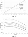
- FIG. 4 is a curve comparison diagram of a bias current changing with temperature in an embodiment of the present invention. From comparison of a bias current changing with temperature in the present invention and a bias current changing with temperature in the conventional technology, it can be learned that the bias current in the present invention has a characteristic of zero temperature coefficient, and has less change than the bias current in the conventional technology.
- FIG. 5 is a curve diagram of a bias current under different PVT conditions changing with temperature in an embodiment of the present invention. As shown in FIG. 5 , under different PVT conditions, the bias current in the present invention has a characteristic of zero temperature coefficient.
- FIG. 6 is a comparison diagram of a non-overshoot starting voltage waveform and an overshoot starting voltage waveform in an embodiment of the present invention.
- a voltage waveform directly approaches 1.2 V and quickly stabilizes at 1.2 V.
- a voltage waveform exceeds a reference voltage and reaches about 2.6 V before finally stabilizing at 1.2 V.
- FIG. 7 is a waveform diagram of a starting voltage of a bandgap reference circuit under different PVT conditions in an embodiment of the present invention. As shown in FIG. 7 , an output voltage of the bandgap reference circuit provided in the present invention can implement a overshoot-free fast start-up under different PVT conditions.
- a overshoot-free fast start-up bandgap reference circuit provided in embodiments of the present invention may be used in an integrated circuit chip.
- a specific structure of the overshoot-free fast start-up bandgap reference circuit in the integrated circuit chip is not described in detail herein again.
- the foregoing overshoot-free fast start-up bandgap reference circuit may also be used in an electronic device as an important part of an analog integrated circuit.
- the electronic device herein refers to a computer device that may be used in a mobile environment and support a plurality of communication standards such as GSM, EDGE, TD-SCDMA, TDD-LTE, and FDD-LTE, including a mobile phone, a laptop, a tablet, a vehicle-mounted computer, and the like.
- GSM Global System for Mobile communications
- EDGE EDGE
- TD-SCDMA Time Division Duplex Code Division Multiple Access
- TDD-LTE Time Division Duplex
- FDD-LTE Frequency Division Duplex
- the technical solutions provided in embodiments of the present invention are also applicable to another analog integrated circuit application scenario, such as a communication base station.
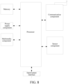
- the electronic device includes at least a processor and a memory, and may further include a communication component, a sensor component, a power supply component, a multimedia component, and an input/output interface according to actual needs.
- the memory, the communication component, the sensor component, the power supply component, the multimedia component, and the input/output interface are all connected to the processor.
- the memory may be a static random access memory (SRAM), an electrically erasable programmable read-only memory (EEPROM), an erasable programmable read-only memory (EPROM), a programmable read-only memory (PROM), a read-only memory (ROM), a magnetic memory, a flash memory, and the like.
- the processor may be a central processing unit (CPU), a graphics processing unit (GPU), a field-programmable gate array (FPGA), an application-specific integrated circuit (ASIC), a digital signal processing (DSP) chip, and the like.
- CPU central processing unit
- GPU graphics processing unit
- FPGA field-programmable gate array
- ASIC application-specific integrated circuit
- DSP digital signal processing
- the overshoot-free fast start-up bandgap reference circuit implemented in the present invention implements a characteristic that the bias current is not related to a power supply voltage and has a zero-temperature coefficient by using a self-biased cascode current mirror structure and resistors with different temperature coefficient types.
- an establishment process of a loop bias point voltage and an output voltage of an operational amplifier is accelerated in a pre-charge manner, so that a overshoot-free fast start-up of the bandgap reference circuit can be implemented under all PVT conditions, enabling the electronic device to have low power consumption and low latency performance.
Landscapes
- Engineering & Computer Science (AREA)
- Physics & Mathematics (AREA)
- Microelectronics & Electronic Packaging (AREA)
- Electromagnetism (AREA)
- General Physics & Mathematics (AREA)
- Radar, Positioning & Navigation (AREA)
- Automation & Control Theory (AREA)
- Nonlinear Science (AREA)
- Power Engineering (AREA)
- Control Of Electrical Variables (AREA)
Applications Claiming Priority (2)
| Application Number | Priority Date | Filing Date | Title |
|---|---|---|---|
| CN202111607944.1A CN113985957B (zh) | 2021-12-27 | 2021-12-27 | 一种无过冲快速启动带隙基准电路、芯片及电子设备 |
| PCT/CN2022/141152 WO2023125250A2 (zh) | 2021-12-27 | 2022-12-22 | 一种无过冲快速启动带隙基准电路、芯片及电子设备 |
Publications (2)
| Publication Number | Publication Date |
|---|---|
| EP4459415A2 true EP4459415A2 (de) | 2024-11-06 |
| EP4459415A4 EP4459415A4 (de) | 2025-12-24 |
Family
ID=79734450
Family Applications (1)
| Application Number | Title | Priority Date | Filing Date |
|---|---|---|---|
| EP22914504.0A Pending EP4459415A4 (de) | 2021-12-27 | 2022-12-22 | Überschwingfreie schnellstart-bandlückenreferenzschaltung, chip und elektronische vorrichtung |
Country Status (6)
| Country | Link |
|---|---|
| US (1) | US20240152172A1 (de) |
| EP (1) | EP4459415A4 (de) |
| JP (1) | JP2024545801A (de) |
| KR (1) | KR20240015138A (de) |
| CN (1) | CN113985957B (de) |
| WO (1) | WO2023125250A2 (de) |
Families Citing this family (7)
| Publication number | Priority date | Publication date | Assignee | Title |
|---|---|---|---|---|
| CN113311898B (zh) * | 2021-07-30 | 2021-12-17 | 唯捷创芯(天津)电子技术股份有限公司 | 一种具有电源抑制的ldo电路、芯片及通信终端 |
| CN113985957B (zh) * | 2021-12-27 | 2022-04-05 | 唯捷创芯(天津)电子技术股份有限公司 | 一种无过冲快速启动带隙基准电路、芯片及电子设备 |
| CN115047930B (zh) * | 2022-05-26 | 2024-05-17 | 南京理工大学 | 一种带隙基准电路 |
| US20240319754A1 (en) * | 2023-03-24 | 2024-09-26 | Samsung Electronics Co., Ltd. | Managing curvature compensation in bandgap reference voltage output in compensation circuit |
| CN116526978B (zh) * | 2023-04-06 | 2024-06-11 | 北京兆讯恒达技术有限公司 | 一种抗干扰快速起振的单端晶振电路及电子设备 |
| CN117008676B (zh) * | 2023-08-17 | 2024-05-31 | 荣湃半导体(上海)有限公司 | 一种用于带隙基准电路的自启动电路 |
| CN119788067B (zh) * | 2024-11-22 | 2025-10-24 | 西安电子科技大学 | 一种具有温度补偿的自启停突发模式时钟与数据恢复电路 |
Family Cites Families (21)
| Publication number | Priority date | Publication date | Assignee | Title |
|---|---|---|---|---|
| US7184204B2 (en) * | 2003-07-01 | 2007-02-27 | Lambda Physik Ag | Master-oscillator power-amplifier (MOPA) excimer or molecular fluorine laser system with long optics lifetime |
| US7161432B2 (en) * | 2005-04-18 | 2007-01-09 | Analog Devices, Inc. | Current mirror with low headroom requirement |
| JP5272467B2 (ja) * | 2008-03-21 | 2013-08-28 | ミツミ電機株式会社 | 基準電圧発生回路およびリセット回路を内蔵した半導体集積回路 |
| WO2011033708A1 (ja) * | 2009-09-18 | 2011-03-24 | パナソニック株式会社 | ドライバ回路および映像システム |
| EP2498162B1 (de) * | 2011-03-07 | 2014-04-30 | Dialog Semiconductor GmbH | Startschaltung für Niederspannungsstromgenerator eines Kaskoden-Beta-Multiplikators |
| US9035641B1 (en) * | 2011-06-06 | 2015-05-19 | Altera Corporation | Startup circuit |
| CN102270008B (zh) * | 2011-06-23 | 2013-06-12 | 西安电子科技大学 | 宽输入带曲率补偿的带隙基准电压源 |
| CN103809645B (zh) * | 2014-03-05 | 2015-05-27 | 电子科技大学 | 一种用于宽电源带隙基准源的启动电路 |
| CN103809647A (zh) * | 2014-03-13 | 2014-05-21 | 苏州芯动科技有限公司 | 一种高电源抑制比基准电压源 |
| US10145728B2 (en) * | 2014-09-15 | 2018-12-04 | Stmicroelectronics S.R.L. | Reception and transmission circuit for a capacitive micromachined ultrasonic transducer |
| CN106155172A (zh) * | 2015-03-31 | 2016-11-23 | 成都锐成芯微科技有限责任公司 | 一种具有无过冲特性的启动电路及带隙基准电路 |
| CN104932601B (zh) * | 2015-06-26 | 2017-11-07 | 华南理工大学 | 一种高电源抑制比的带隙基准电压源 |
| CN111610812B (zh) * | 2019-02-26 | 2022-08-30 | 武汉杰开科技有限公司 | 一种带隙基准电源产生电路及集成电路 |
| CN109947169B (zh) * | 2019-04-23 | 2020-03-31 | 电子科技大学 | 一种具有预稳压结构的高电源抑制比带隙基准电路 |
| CN110096091B (zh) * | 2019-06-11 | 2021-09-21 | 上海复旦微电子集团股份有限公司 | 一种耐压亚阈值cmos基准源电路 |
| CN110568898B (zh) * | 2019-09-25 | 2021-06-08 | 上海华虹宏力半导体制造有限公司 | 带隙基准源的启动电路 |
| CN111240394B (zh) * | 2020-01-15 | 2021-11-09 | 西安电子科技大学 | 带预稳压结构的无运放带隙基准电路 |
| TWI727673B (zh) * | 2020-02-25 | 2021-05-11 | 瑞昱半導體股份有限公司 | 偏壓電流產生電路 |
| CN113220060B (zh) * | 2021-04-30 | 2022-08-09 | 深圳市国微电子有限公司 | 高电源抑制比的带隙基准电路和电子设备 |
| CN113311898B (zh) * | 2021-07-30 | 2021-12-17 | 唯捷创芯(天津)电子技术股份有限公司 | 一种具有电源抑制的ldo电路、芯片及通信终端 |
| CN113985957B (zh) * | 2021-12-27 | 2022-04-05 | 唯捷创芯(天津)电子技术股份有限公司 | 一种无过冲快速启动带隙基准电路、芯片及电子设备 |
-
2021
- 2021-12-27 CN CN202111607944.1A patent/CN113985957B/zh active Active
-
2022
- 2022-12-22 WO PCT/CN2022/141152 patent/WO2023125250A2/zh not_active Ceased
- 2022-12-22 JP JP2024505300A patent/JP2024545801A/ja active Pending
- 2022-12-22 KR KR1020247000195A patent/KR20240015138A/ko active Pending
- 2022-12-22 EP EP22914504.0A patent/EP4459415A4/de active Pending
-
2024
- 2024-01-16 US US18/413,036 patent/US20240152172A1/en active Pending
Also Published As
| Publication number | Publication date |
|---|---|
| EP4459415A4 (de) | 2025-12-24 |
| CN113985957B (zh) | 2022-04-05 |
| KR20240015138A (ko) | 2024-02-02 |
| US20240152172A1 (en) | 2024-05-09 |
| JP2024545801A (ja) | 2024-12-12 |
| CN113985957A (zh) | 2022-01-28 |
| WO2023125250A3 (zh) | 2023-09-21 |
| WO2023125250A2 (zh) | 2023-07-06 |
Similar Documents
| Publication | Publication Date | Title |
|---|---|---|
| EP4459415A2 (de) | Überschwingfreie schnellstart-bandlückenreferenzschaltung, chip und elektronische vorrichtung | |
| US20250334985A1 (en) | Ldo circuit having current limiting function, and chip and electronic device | |
| KR100400304B1 (ko) | 커런트 미러형의 밴드갭 기준전압 발생장치 | |
| JP4866158B2 (ja) | レギュレータ回路 | |
| US12411509B2 (en) | LDO circuit having power supply rejection function, chip and communication terminal | |
| CN113050750B (zh) | 一种能够实现宽输入范围和快速稳态的低压差线性稳压器 | |
| TW201413416A (zh) | 具備電壓產生電路之半導體裝置 | |
| CN111190453B (zh) | 高电源抑制比基准电路 | |
| CN102609031B (zh) | 一种高度集成的低功耗基准源 | |
| CN113485514A (zh) | 一种ldo过流保护电路 | |
| CN115328245A (zh) | 偏置电流产生电路 | |
| WO2024208336A1 (zh) | 一种瞬态响应的低压差线性稳压器、芯片和电子设备 | |
| EP1852766B1 (de) | Referenzspannungs-erzeugungsschaltung | |
| JP2003007837A (ja) | 基準電圧回路 | |
| CN117970989A (zh) | 稳压器电路 | |
| CN114442719B (zh) | 带隙基准电压源 | |
| CN118981231A (zh) | 一种快速瞬态响应的无片外电容ldo电路 | |
| CN117742439A (zh) | 基准电压发生电路及包含其的射频模组 | |
| CN115756065A (zh) | 带隙基准电路、芯片、带隙基准电压源及电子设备 | |
| CN111629463B (zh) | 一种振荡电路 | |
| CN212623800U (zh) | 一种稳压器 | |
| CN116633116A (zh) | 低功耗电流源、电流源电路、芯片及具有其的电子设备 | |
| CN119065438B (zh) | 电源电压快速变化应用中的线性稳压器电路及芯片 | |
| CN118939053A (zh) | 前置稳压电路 | |
| CN117666690A (zh) | 带隙基准电路和电子设备 |
Legal Events
| Date | Code | Title | Description |
|---|---|---|---|
| STAA | Information on the status of an ep patent application or granted ep patent |
Free format text: STATUS: THE INTERNATIONAL PUBLICATION HAS BEEN MADE |
|
| PUAI | Public reference made under article 153(3) epc to a published international application that has entered the european phase |
Free format text: ORIGINAL CODE: 0009012 |
|
| STAA | Information on the status of an ep patent application or granted ep patent |
Free format text: STATUS: REQUEST FOR EXAMINATION WAS MADE |
|
| 17P | Request for examination filed |
Effective date: 20240122 |
|
| AK | Designated contracting states |
Kind code of ref document: A2 Designated state(s): AL AT BE BG CH CY CZ DE DK EE ES FI FR GB GR HR HU IE IS IT LI LT LU LV MC ME MK MT NL NO PL PT RO RS SE SI SK SM TR |
|
| DAV | Request for validation of the european patent (deleted) | ||
| DAX | Request for extension of the european patent (deleted) | ||
| A4 | Supplementary search report drawn up and despatched |
Effective date: 20251121 |
|
| RIC1 | Information provided on ipc code assigned before grant |
Ipc: G05F 1/567 20060101AFI20251117BHEP Ipc: G05F 3/26 20060101ALI20251117BHEP |