EP4459037A1 - Trockner und verfahren zur steuerung davon - Google Patents
Trockner und verfahren zur steuerung davon Download PDFInfo
- Publication number
- EP4459037A1 EP4459037A1 EP23819959.0A EP23819959A EP4459037A1 EP 4459037 A1 EP4459037 A1 EP 4459037A1 EP 23819959 A EP23819959 A EP 23819959A EP 4459037 A1 EP4459037 A1 EP 4459037A1
- Authority
- EP
- European Patent Office
- Prior art keywords
- drum
- rotation
- motor
- dryer
- time
- Prior art date
- Legal status (The legal status is an assumption and is not a legal conclusion. Google has not performed a legal analysis and makes no representation as to the accuracy of the status listed.)
- Pending
Links
Images




Classifications
-
- D—TEXTILES; PAPER
- D06—TREATMENT OF TEXTILES OR THE LIKE; LAUNDERING; FLEXIBLE MATERIALS NOT OTHERWISE PROVIDED FOR
- D06F—LAUNDERING, DRYING, IRONING, PRESSING OR FOLDING TEXTILE ARTICLES
- D06F34/00—Details of control systems for washing machines, washer-dryers or laundry dryers
- D06F34/14—Arrangements for detecting or measuring specific parameters
- D06F34/18—Condition of the laundry, e.g. nature or weight
-
- D—TEXTILES; PAPER
- D06—TREATMENT OF TEXTILES OR THE LIKE; LAUNDERING; FLEXIBLE MATERIALS NOT OTHERWISE PROVIDED FOR
- D06F—LAUNDERING, DRYING, IRONING, PRESSING OR FOLDING TEXTILE ARTICLES
- D06F34/00—Details of control systems for washing machines, washer-dryers or laundry dryers
- D06F34/14—Arrangements for detecting or measuring specific parameters
- D06F34/20—Parameters relating to constructional components, e.g. door sensors
-
- D—TEXTILES; PAPER
- D06—TREATMENT OF TEXTILES OR THE LIKE; LAUNDERING; FLEXIBLE MATERIALS NOT OTHERWISE PROVIDED FOR
- D06F—LAUNDERING, DRYING, IRONING, PRESSING OR FOLDING TEXTILE ARTICLES
- D06F34/00—Details of control systems for washing machines, washer-dryers or laundry dryers
- D06F34/28—Arrangements for program selection, e.g. control panels therefor; Arrangements for indicating program parameters, e.g. the selected program or its progress
-
- D—TEXTILES; PAPER
- D06—TREATMENT OF TEXTILES OR THE LIKE; LAUNDERING; FLEXIBLE MATERIALS NOT OTHERWISE PROVIDED FOR
- D06F—LAUNDERING, DRYING, IRONING, PRESSING OR FOLDING TEXTILE ARTICLES
- D06F34/00—Details of control systems for washing machines, washer-dryers or laundry dryers
- D06F34/28—Arrangements for program selection, e.g. control panels therefor; Arrangements for indicating program parameters, e.g. the selected program or its progress
- D06F34/30—Arrangements for program selection, e.g. control panels therefor; Arrangements for indicating program parameters, e.g. the selected program or its progress characterised by mechanical features, e.g. buttons or rotary dials
-
- D—TEXTILES; PAPER
- D06—TREATMENT OF TEXTILES OR THE LIKE; LAUNDERING; FLEXIBLE MATERIALS NOT OTHERWISE PROVIDED FOR
- D06F—LAUNDERING, DRYING, IRONING, PRESSING OR FOLDING TEXTILE ARTICLES
- D06F34/00—Details of control systems for washing machines, washer-dryers or laundry dryers
- D06F34/28—Arrangements for program selection, e.g. control panels therefor; Arrangements for indicating program parameters, e.g. the selected program or its progress
- D06F34/32—Arrangements for program selection, e.g. control panels therefor; Arrangements for indicating program parameters, e.g. the selected program or its progress characterised by graphical features, e.g. touchscreens
-
- D—TEXTILES; PAPER
- D06—TREATMENT OF TEXTILES OR THE LIKE; LAUNDERING; FLEXIBLE MATERIALS NOT OTHERWISE PROVIDED FOR
- D06F—LAUNDERING, DRYING, IRONING, PRESSING OR FOLDING TEXTILE ARTICLES
- D06F34/00—Details of control systems for washing machines, washer-dryers or laundry dryers
- D06F34/28—Arrangements for program selection, e.g. control panels therefor; Arrangements for indicating program parameters, e.g. the selected program or its progress
- D06F34/34—Arrangements for program selection, e.g. control panels therefor; Arrangements for indicating program parameters, e.g. the selected program or its progress characterised by mounting or attachment features, e.g. detachable control panels or detachable display panels
-
- D—TEXTILES; PAPER
- D06—TREATMENT OF TEXTILES OR THE LIKE; LAUNDERING; FLEXIBLE MATERIALS NOT OTHERWISE PROVIDED FOR
- D06F—LAUNDERING, DRYING, IRONING, PRESSING OR FOLDING TEXTILE ARTICLES
- D06F58/00—Domestic laundry dryers
- D06F58/02—Domestic laundry dryers having dryer drums rotating about a horizontal axis
- D06F58/04—Details
- D06F58/08—Driving arrangements
-
- D—TEXTILES; PAPER
- D06—TREATMENT OF TEXTILES OR THE LIKE; LAUNDERING; FLEXIBLE MATERIALS NOT OTHERWISE PROVIDED FOR
- D06F—LAUNDERING, DRYING, IRONING, PRESSING OR FOLDING TEXTILE ARTICLES
- D06F58/00—Domestic laundry dryers
- D06F58/32—Control of operations performed in domestic laundry dryers
- D06F58/34—Control of operations performed in domestic laundry dryers characterised by the purpose or target of the control
- D06F58/36—Control of operational steps, e.g. for optimisation or improvement of operational steps depending on the condition of the laundry
- D06F58/38—Control of operational steps, e.g. for optimisation or improvement of operational steps depending on the condition of the laundry of drying, e.g. to achieve the target humidity
-
- D—TEXTILES; PAPER
- D06—TREATMENT OF TEXTILES OR THE LIKE; LAUNDERING; FLEXIBLE MATERIALS NOT OTHERWISE PROVIDED FOR
- D06F—LAUNDERING, DRYING, IRONING, PRESSING OR FOLDING TEXTILE ARTICLES
- D06F58/00—Domestic laundry dryers
- D06F58/32—Control of operations performed in domestic laundry dryers
- D06F58/34—Control of operations performed in domestic laundry dryers characterised by the purpose or target of the control
- D06F58/52—Preventing or reducing noise
-
- D—TEXTILES; PAPER
- D06—TREATMENT OF TEXTILES OR THE LIKE; LAUNDERING; FLEXIBLE MATERIALS NOT OTHERWISE PROVIDED FOR
- D06F—LAUNDERING, DRYING, IRONING, PRESSING OR FOLDING TEXTILE ARTICLES
- D06F2101/00—User input for the control of domestic laundry washing machines, washer-dryers or laundry dryers
- D06F2101/20—Operation modes, e.g. delicate laundry washing programs, service modes or refreshment cycles
-
- D—TEXTILES; PAPER
- D06—TREATMENT OF TEXTILES OR THE LIKE; LAUNDERING; FLEXIBLE MATERIALS NOT OTHERWISE PROVIDED FOR
- D06F—LAUNDERING, DRYING, IRONING, PRESSING OR FOLDING TEXTILE ARTICLES
- D06F2103/00—Parameters monitored or detected for the control of domestic laundry washing machines, washer-dryers or laundry dryers
- D06F2103/02—Characteristics of laundry or load
- D06F2103/04—Quantity, e.g. weight or variation of weight
-
- D—TEXTILES; PAPER
- D06—TREATMENT OF TEXTILES OR THE LIKE; LAUNDERING; FLEXIBLE MATERIALS NOT OTHERWISE PROVIDED FOR
- D06F—LAUNDERING, DRYING, IRONING, PRESSING OR FOLDING TEXTILE ARTICLES
- D06F2103/00—Parameters monitored or detected for the control of domestic laundry washing machines, washer-dryers or laundry dryers
- D06F2103/24—Spin speed; Drum movements
-
- D—TEXTILES; PAPER
- D06—TREATMENT OF TEXTILES OR THE LIKE; LAUNDERING; FLEXIBLE MATERIALS NOT OTHERWISE PROVIDED FOR
- D06F—LAUNDERING, DRYING, IRONING, PRESSING OR FOLDING TEXTILE ARTICLES
- D06F2103/00—Parameters monitored or detected for the control of domestic laundry washing machines, washer-dryers or laundry dryers
- D06F2103/26—Imbalance; Noise level
-
- D—TEXTILES; PAPER
- D06—TREATMENT OF TEXTILES OR THE LIKE; LAUNDERING; FLEXIBLE MATERIALS NOT OTHERWISE PROVIDED FOR
- D06F—LAUNDERING, DRYING, IRONING, PRESSING OR FOLDING TEXTILE ARTICLES
- D06F2103/00—Parameters monitored or detected for the control of domestic laundry washing machines, washer-dryers or laundry dryers
- D06F2103/38—Time, e.g. duration
-
- D—TEXTILES; PAPER
- D06—TREATMENT OF TEXTILES OR THE LIKE; LAUNDERING; FLEXIBLE MATERIALS NOT OTHERWISE PROVIDED FOR
- D06F—LAUNDERING, DRYING, IRONING, PRESSING OR FOLDING TEXTILE ARTICLES
- D06F2105/00—Systems or parameters controlled or affected by the control systems of washing machines, washer-dryers or laundry dryers
- D06F2105/46—Drum speed; Actuation of motors, e.g. starting or interrupting
-
- D—TEXTILES; PAPER
- D06—TREATMENT OF TEXTILES OR THE LIKE; LAUNDERING; FLEXIBLE MATERIALS NOT OTHERWISE PROVIDED FOR
- D06F—LAUNDERING, DRYING, IRONING, PRESSING OR FOLDING TEXTILE ARTICLES
- D06F2105/00—Systems or parameters controlled or affected by the control systems of washing machines, washer-dryers or laundry dryers
- D06F2105/46—Drum speed; Actuation of motors, e.g. starting or interrupting
- D06F2105/48—Drum speed
-
- D—TEXTILES; PAPER
- D06—TREATMENT OF TEXTILES OR THE LIKE; LAUNDERING; FLEXIBLE MATERIALS NOT OTHERWISE PROVIDED FOR
- D06F—LAUNDERING, DRYING, IRONING, PRESSING OR FOLDING TEXTILE ARTICLES
- D06F2105/00—Systems or parameters controlled or affected by the control systems of washing machines, washer-dryers or laundry dryers
- D06F2105/52—Changing sequence of operational steps; Carrying out additional operational steps; Modifying operational steps, e.g. by extending duration of steps
-
- D—TEXTILES; PAPER
- D06—TREATMENT OF TEXTILES OR THE LIKE; LAUNDERING; FLEXIBLE MATERIALS NOT OTHERWISE PROVIDED FOR
- D06F—LAUNDERING, DRYING, IRONING, PRESSING OR FOLDING TEXTILE ARTICLES
- D06F58/00—Domestic laundry dryers
- D06F58/02—Domestic laundry dryers having dryer drums rotating about a horizontal axis
- D06F58/04—Details
- D06F58/06—Mountings for the rotating drums
Definitions
- the disclosure relates to a dryer for reducing noise generated when a drum is rotated to dry laundry, such as clothes, and a method of controlling the same.
- a dryer is a device that dries laundry by supplying hot air into a drum containing laundry, such as clothes, towels, blankets, and the like, while rotating the drum.
- the drum of the dryer is supported by at least one roller, and the at least one roller rotates together with the drum during rotation of the drum while helping the drum efficiently rotate. Therefore, the surface of the roller in contact with the drum is formed of a rubber material.
- the weight of the drum is supported by a rear frame on which a rotary shaft of the drum is mounted and at least one roller. Accordingly, while the dryer is not in use, the at least one roller may be deformed by the weight of the drum, and the deformation of the roller may cause rotational initial noise of the drum.
- the disclosure is directed to providing a dryer and a control method that are capable of determining a rotation velocity and a rotation time of a motor based on a non-use time of a dryer in order to reduce rotational initial noise of a drum.
- One aspect of the disclosure provides a dryer according to an aspect of the disclosure includes: a cabinet; a drum rotatably disposed inside the cabinet; at least one roller mounted on at least one surface inside of the cabinet to support the drum; a motor configured to provide power to rotate the drum; a motor driver configured to control the motor; and at least one processor configured to determine at least one of a first rotation velocity of the motor or a first rotation time of the motor based on a non-use time of the dryer, and control the motor driver based on the determined at least one of the first rotation velocity or the first rotation time of the motor.
- the at least one roller may, while the drum is stationary, deform due to a pressure applied from the drum, and while the drum is rotating, restore from the deformation.
- the dryer may further include an input device, wherein the at least one processor may be configured to, upon receiving a user input to select a rotation cycle including a rotation of the drum, perform a noise reduction cycle for reducing noise generated by the deformation of the at least one roller, and start the rotation cycle after performing the noise reduction cycle.
- the at least one processor may be configured to, in a process of performing the noise reduction, determine the at least one of the first rotation velocity of the motor or the first rotation time of the motor based on the non-use time of the dryer, and control the motor driver based on the determined at least one of the first rotation velocity or the first rotation time of the motor.
- the at least one processor may be configured to determine the non-use time of the dryer based on a time gap between a time at which the rotation of the drum may be ended last, and a start time of the rotation cycle or a current time.
- the at least one processor may be configured to determine a maximum revolution per minute (RPM) of the motor at which noise due to the rotation of the drum may not occur as the first rotational velocity of the motor.
- RPM revolution per minute
- the at least one processor may be configured to determine the first rotation time of the motor based on the non-use time of the dryer.
- the first rotation time of the motor may be determined based on a first number of rotations of the drum and the first rotation velocity of the motor corresponding to the non-use time of the dryer.
- the first number of rotations of the drum may correspond to a minimum number of rotations of the drum required to restore the deformation of the at least one roller by rotating the drum.
- the at least one processor may be configured to determine the at least one of the first rotation velocity of the motor or the first rotation time of the motor based on the non-use time of the dryer and an ambient temperature.
- One aspect of the disclosure provides a method of controlling a dryer including a cabinet, a drum rotatably disposed inside the cabinet, at least one roller mounted on at least one surface inside of the cabinet to support the drum, a motor configured to provide power to rotate the drum, and a motor driver configured to control the motor, the method including: determining at least one of a first rotation velocity of the motor or a first rotation time of the motor based on a non-use time of the dryer; and controlling the motor driver based on the determined at least one of the first rotation velocity or the first rotation time of the motor.
- the at least one roller may, while the drum is stationary, deform due to a pressure applied from the drum, and while the drum is rotating, restores from the deformation.
- the method may further include: upon receiving a user input to select a rotation cycle including a rotation of the drum, performing a noise reduction cycle for reducing noise generated by the deformation of the at least one roller; and starting the rotation cycle after performing the noise reduction cycle.
- the performing of the noise reduction may include: determining the at least one of the first rotation velocity of the motor or the first rotation time of the motor based on the non-use time of the dryer; and controlling the motor driver based on the determined at least one of the first rotation velocity or the first rotation time of the motor.
- the determining of the at least one of the first rotation velocity of the motor or the first rotation time of the motor based on the non-use time of the dryer may include determining the non-use time of the dryer based on a time gap between a time at which the rotation of the drum may be ended last, and a start time of the rotation cycle or a current time.
- the determining of the at least one of the first rotation velocity of the motor or the first rotation time of the motor based on the non-use time of the dryer may include determining a maximum revolution per minute (RPM) of the motor at which noise due to the rotation of the drum does not occur as the first rotational velocity of the motor.
- RPM revolution per minute
- the determining of the at least one of the first rotation velocity of the motor or the first rotation time of the motor based on the non-use time of the dryer may include determining the first rotation time of the motor based on the non-use time of the dryer.
- the first rotation time of the motor may be determined based on a first number of rotations of the drum and the first rotation velocity of the motor corresponding to the non-use time of the dryer.
- the first number of rotations of the drum may correspond to a minimum number of rotations of the drum required to restore the deformation of the at least one roller by rotating the drum.
- the determining of the at least one of the first rotation velocity of the motor or the first rotation time of the motor based on the non-use time of the dryer may include determining the at least one of the first rotation velocity of the motor or the first rotation time of the motor based on the non-use time of the dryer and an ambient temperature.
- a dryer according to an aspect of the disclosure and a method of controlling the same are implemented to determine a rotational velocity based on a non-use time of the dryer and perform noise reduction cycle according to the rotation velocity, thereby reducing rotational initial noise of a drum.
- unit may refer to a unit of processing at least one function or operation.
- these terms may refer to a hardware component, such as a field-programmable gate array (FPGA)/an application-specific integrated circuit (ASIC), a software component, or at least one cycle processed by a processor.
- FPGA field-programmable gate array
- ASIC application-specific integrated circuit
- ordinal numbers such as “first ⁇ " and “second ⁇ " used in front of the components described in the specification are only used to distinguish the components from each other without having other meanings, such as the order of connection and use between the components, priority, etc.
- a reference numeral attached in each of operations is used to identify each of the operations, and this reference numeral does not describe the order of the operations, and the operations may be performed differently from the described order unless clearly specified in the context.
- the expression, "at least one of a, b, and c,” should be understood as including only a, only b, only c, both a and b, both a and c, both b and c, or all of a, b, and c.
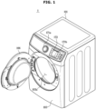
- FIG. 1 is an external view illustrating a dryer according to an embodiment
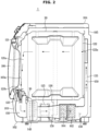
- FIG. 2 is a side sectional view illustrating a dryer according to an embodiment.
- a dryer 1 includes a cabinet 101 accommodating components of the dryer 1 and a drum 20 rotatably installed in the cabinet 101. Laundry, for which drying is to be performed, may be accommodated in the drum 20.
- the cabinet 101 may include a base plate 102, a front cover 103, a top cover 104, and a side/rear cover 105.
- the front cover 103 may be provided with an opening 103a, and the opening 103a may be opened and closed by a door 106 rotatably installed on the front cover 103.
- the drum 20 provided in a cylindrical shape with an open front may also be opened and closed by the door 106.
- the front cover 103 may be provided on an upper portion thereof with input devices 171a and 171b for receiving a user command and a display 172 for displaying various types of information related to the operation of the dryer 1 or displaying a screen that guides user input.
- the input devices 171a and 171b may be provided in the form of a jog shuttle or a dial such that the user may input a command by holding and turning, or pressing the input device 171a, or may be provided in the form of a touch pad or button such that the user may input a command by touching or pressing the input device 171b.
- the display 172 may be implemented by various display panels, such as a liquid crystal display (LCD), a light emitting diode (LED), an organic LED (OLED), a quantum dot LED (QLED), and the like, and may be implemented as a touch screen having a touch pad formed on a front side thereof.
- LCD liquid crystal display
- LED light emitting diode
- OLED organic LED
- QLED quantum dot LED
- a front frame 121 having a laundry inlet 121a may be disposed on the front side of the drum 20, and laundry may be loaded into the drum 20 through the laundry inlet 121a.
- the rear side of the drum 20 may be closed by a rear frame 122 provided with an inlet 122a through which hot dry air is introduced.
- the front frame 121 may be provided with an outlet 121b through which air used to dry laundry is discharged, and a filter 123 for collecting foreign substances generated from the laundry may be installed in the outlet 121b.
- At least one lifter may be formed in a protrusion manner on an inner wall of the drum 20 to assist in tumbling of laundry.
- the drum 20 may be rotated by power provided from a drum motor 125.
- the drum 20 may be connected to the drum motor 125 by a belt 126, and the belt 126 may transmit power provided from the drum motor 125 to the drum 20.
- the drum 20 may be disposed such that the axis of rotation is parallel to the ground, and the axis of rotation of the drum 20 may be mounted on the rear frame 122.
- a heater type is configured in a way to supply air heated by a heater to the inside of a drum to dry laundry
- a heat pump type is configured to remove moisture from laundry to dry the laundry.
- a case in which the dryer 1 dries laundry by a heat pump method will be described as an example.
- an air-vent type is configured in a way to discharge high-temperature and high-humidity air to the outside of the dryer 1
- a condensing type is configured in a way to remove moisture from high-temperature and high-humidity air and then circulate the air back into the drum 20.
- a case in which the dryer 1 employs a condensing method will be described as an example.
- the dryer 1 may include a fan 140 circulating air inside the drum 20.
- the fan 140 may suction air from inside the drum 20 and discharge the air through a duct 150. By the operation of the fan 140, air inside the drum 20 may circulate between the drum 20 and the duct 150.
- a heat pump may be provided on the duct 150 through which air inside the drum 20 may circulate.
- the heat pump may include a compressor (not shown), a condenser 162, an evaporator 164, and an expander (not shown).
- the compressor may compress a gaseous refrigerant into a high-temperature and high-pressure refrigerant, and discharge the compressed high-temperature and high-pressure gaseous refrigerant.
- the compressor may compress the refrigerant through a reciprocating motion of a piston or a rotation motion of a rotary wheel.
- the discharged refrigerant is delivered to the condenser 162.
- the condenser 162 may condense the compressed gaseous refrigerant into a liquid while discharging heat to surroundings.
- the condenser 162 may be provided on the duct 150, and the heat generated in the process of condensing the refrigerant may allow air to be heated.
- the heated air may be supplied to the drum 20.
- the liquid refrigerant condensed in the condenser 162 may be delivered to an expander (not shown).
- the expander may expand the high-temperature and high-pressure liquid refrigerant condensed in the condenser 162 into a low-pressure liquid refrigerant.
- the expander may include a capillary tube and an electronic expansion valve, of which the opening degree may be varied by an electric signal, for adjusting the pressure of the liquid refrigerant.
- the evaporator 164 may evaporate the liquid refrigerant expanded in the expander. As a result, the evaporator may return the low-temperature and low-pressure gaseous refrigerant to the compressor.
- the evaporator 164 may absorb heat from the surroundings through an evaporation process in which a low-pressure liquid refrigerant is converted into a gaseous refrigerant.
- the evaporator 164 may be provided on the duct 150 so that air passing through the evaporator 164 may be cooled in the evaporation process.
- the evaporator 164 may cause the ambient air to be cooled, and when the temperature of the ambient air becomes lower than the dew point, the air around the evaporator 164 may be condensed.
- the water condensed in the evaporator 164 may be collected by a water trap provided at a lower side of the evaporator 164. The water collected in the water trap may be moved to a separate storage or drained to the outside of the dryer 1.
- the absolute humidity of air passing through the evaporator 164 may be lowered. In other words, the amount of water vapor included in the air passing through the evaporator 164 may decrease.
- the dryer 1 may reduce the amount of water vapor contained in the air inside the drum 20 and dry laundry.
- the evaporator 164 may be located upstream of the condenser 162 based on a flow of air by the fan 140.
- the air circulating by the fan 140 may be dried (water vapor is condensed) by the evaporator 164 while passing through the evaporator 164, and then heated by the condenser 162 while passing through the condenser 162.
- the duct 150 may be provided with a heater 155 for heating air while assisting the condenser 162.
- the heater 155 may be located downstream of the condenser 162 based on a flow of air by the fan 140.
- air heated in the condenser 162 of the heat pump 160 may be additionally heated by the heater 155 such that the air in the duct 150 may be sufficiently heated.
- the internal temperature of the drum 20 may rise more rapidly, and the time required to dry laundry may be shortened.
- FIG. 3 is a perspective view illustrating a drum and some configurations of a dryer according to an embodiment.
- FIG. 4 is a perspective view illustrating a drum and some configurations of a dryer according to an embodiment.
- At least one roller 30 supporting the drum 20 may be mounted on the front frame 121. Specifically, the at least one roller 30 may be provided at a position in contact with the drum 20 in a lower portion of the drum 20. Accordingly, in a state in which the drum 20 is stopped, at least one roller 30 may support at least part of the weight of the drum 20.
- the at least one roller 30 may rotate together with the drum 20.
- the at least one roller 30 may rotate in a direction opposite to the rotating direction of the drum 20 to efficiently assist the rotation of the drum 20.
- a surface of the at least one roller 30 that is in contact with the drum 20 may be formed of a rubber material so that noise generated by a contact between the drum 20 and the at least one roller 30 may be minimized.
- the at least one roller 30 is provided only at a position in contact with the drum 20 in the lower portion of the drum 20 is illustrated, but embodiments of the dryer 1 are not limited thereto. According to a design change by a person skilled in the art, the at least one roller 30 may be provided even at a position in contact with the drum 20 in an upper portion of the drum 20 so that rotation of the drum 20 may be smoothly performed.
- the at least one roller 30 may be provided on the rear frame 122 to support the drum 20 on the front and rear of the drum 20 while assisting the rotation of the drum 20.
- FIG. 5 and FIG. 6 are a table and a graph showing the degree of deformation of a roller according to a non-use time of a dryer according to an embodiment.
- the at least one roller 30, in particular, the at least one roller 30 provided at a position in contact with the drum 20 in the lower portion of the drum 20 will support at least part of the weight of the
- pressure may be applied to the at least one roller 30, and the at least one roller 30, of which the surface is formed of a rubber material, may be subject deformation, such as compression, twist, and the like by the pressure applied in a stationary state of the drum 20.
- the degree to which the surface of the rubber roller 30 is pressed by the drum 20 depending on the non-use time of the dryer 1 was measured at different ambient temperatures, and the measurement results are shown in the table of FIG. 5 and the graph of FIG. 6 .
- the ambient temperature may represent the temperature of the surrounding of the at least one roller 30.
- the ambient temperature may represent the temperature of a space in which the dryer 1 is located, or may be a temperature measured by a temperature sensor provided at a surrounding of the roller 30 inside the dryer 1.
- the ambient temperature may vary depending on the region in which the dryer 1 is used, or may vary depending on the season even in the same region. Due to the nature of the rubber material, the degree of deformation of the roller 30 may vary depending on the ambient temperature even when the same pressure is applied.
- the degree of deformation of the roller 30 does not continue to increase in proportion to the increasing non-use time of the dryer 1, and as shown in FIGS. 5 and 6 , the degree of deformation of the roller 30 becomes constant when a certain period of time elapses.
- the shape of the roller 30 deformed as described above may be restored to the original state when the stopped drum 20 rotates again. That is, the deformation of the roller 30 due to the weight of the stopped drum 20 is a short-period deformation.
- the dryer 1 may perform a noise reduction cycle of reducing noise generated in the early stage of rotation of a drum 20 due to the deformed shape of the roller 30 before a main cycle of the dryer 1 starts, thereby reducing inconvenience in use of the dryer 1 due to noise.
- a noise reduction cycle of reducing noise generated in the early stage of rotation of a drum 20 due to the deformed shape of the roller 30 before a main cycle of the dryer 1 starts, thereby reducing inconvenience in use of the dryer 1 due to noise.
- FIG. 7 is a block diagram illustrating an operation of a dryer according to an embodiment.
- the dryer 1 may include a heat pump 160, an input device 171, a display 172, a speaker 173, and a motor driver 180 described above, and may further include a controller 110 and a sensor module 130.
- the sensor module 130 may include at least one sensor that measures various types of data required for controlling the dryer 1.
- the sensor module 130 may include a humidity sensor for measuring the humidity of laundry loaded into the drum 20, a temperature sensor for measuring the ambient temperature of the dryer 1 or the temperature inside the dryer 1 (e.g., the temperature of the surrounding of the roller 30).
- the controller 110 may control the overall operation of the dryer 1.
- the controller 110 may control components of the dryer 1 based on a user input received by the input device 171 or data measured by the sensor module 130.
- the controller 110 may include at least one memory 111 storing a program for performing operations described below and at least one processor 112 executing the stored program.
- the controller 110 may be implemented as a microcontroller unit (MCU).
- MCU microcontroller unit
- a cycle selectable by the user through the input device 171 may include a drying cycle for drying laundry and an additional cycle.
- the additional cycle may include a dusting cycle, a functional clothes care cycle for padding or outdoor clothing, and the like.
- the controller 110 may determine a rotation velocity and a rotation time of the drum motor 125 for rotating the drum 20, and control the motor driver 180 according to the determined rotation velocity and the determined rotation time to rotate the drum motor 125.
- the rotation velocity and the rotation time of the drum motor 125 for the drying cycle may be determined based on factors, such as the weight of a laundry to be dried, the humidity of the laundry, and the type of the laundry.
- the humidity of the laundry may be measured by the above described humidity sensor, and information about the type of the laundry may be input by a user through the input device 171.
- the user may input information about the type of the laundry, such as blankets, towels, delicate clothes, wool, shirts, and denim, through the input device 171.
- the sensor module 130 may detect the type of laundry.
- the weight of the laundry may be determined by at least one of various methods for detecting the weight.
- the controller 110 may determine the weight of the laundry by performing a weight sensing cycle before starting a drying cycle. In the weight sensing cycle, the controller 110 may rotate the drum 20 at a high velocity for a predetermined period of time and determine the weight of the laundry based on a load applied to the drum motor 125 during the rotation of the drum 20.
- the shape of the roller 30 may be deformed due to the weight of the drum 20 during a non-use time of the dryer 1, and when the drum 20 rotates in a state in which the shape of the roller 30 is deformed, noise may occur due to friction between the roller 30 and the drum 20 having an irregular shape.
- the controller 110 may perform a noise reduction cycle for reducing noise caused by rotation of the drum 20 before starting a cycle including rotations of the drum 20.
- the cycle including rotations of the drum 20 may include a drying cycle for drying laundry and a dusting cycle for dusting blankets or carpets.
- a cycle including rotations of the drum 20 will be referred to as a rotation cycle.
- the deformation of the roller 30 caused by the weight of the drum 20 is temporary, and when the drum 20 rotates again while in contact with the drum 20, the deformed shape of the roller 30 returns to the original shape.
- the controller 110 may rotate the drum 20 at an appropriate velocity for an appropriate time to perform the noise reduction cycle, and a rotation velocity and a rotation time of the drum motor 125 for rotating the drum 20 at the appropriate velocity for the appropriate time may be determined based on the non-use time of the dryer 1.
- the non-use time of the dryer 1 may indicate the time for which the drum 20 remains stopped.
- the rotation velocity and the rotation time of the drum motor 125 corresponding to the non-use time of the dryer 1 may be determined based on data obtained through experiments.
- the rotation velocity and the rotation time of the drum motor 125 corresponding to the non-use time of the dryer 1 refer to a rotation velocity and a rotation time of the drum motor 125 that allow the roller 30 to restore the original shape without generating noise caused by rotations of the drum 20 in a process of rotating the drum 20 after the dryer 1 has not been used for a time corresponding to the non-use time.
- the rotation velocity and the rotation time of the drum motor 125 may be referred to as a first rotation velocity and a first rotation time, respectively.
- Data used to determine the first rotation velocity and the first rotation time of the drum motor 125 may be obtained through experiments in a manufacturing process of the dryer 1. The data may be obtained for each individual dryer 1, for each model of the dryer 1, or for each size or weight of the drum 20.
- a criterion for obtaining the data may not be limited, and the data may be shared by a plurality of dryers 1 as long as it is data for a dryer 1 that exhibits the same or similar deformation characteristics and restoration characteristics of the roller 30.
- FIG. 8 is a table showing a pulley ratio of a motor and a drum of a dryer used in an experiment
- FIG. 9 is a table showing a noise-free condition according to the degree of deformation of a roller.
- the drum 20 has a rotation velocity of 8.8RPM at a rotation velocity of 400RPM of the drum motor 125, has a rotation velocity of 17.7RPM at a rotation velocity of 800RPM of the drum motor 125, and has a rotation velocity of 26.5RPM at a rotation velocity of 1200RPM of the drum motor 125. That is, the pulley ratio is 45.2.
- FIG. 9 a result measuring the maximum RPM of the drum motor 125, at which noise is not generated, by varying the degree of deformation of the roller 30 (the amounts of pressing on the rubber surface) for five dryers 1 of the same model is shown.
- each of the dryers 1 is indicated as SET 1, SET 2, SET 3, SET 4, and SET 5.
- Rotational initial noise generated in the early stage of rotation when the drum 20 rotates in a state in which the roller 30 is deformed increases in proportion to the increasing rotation velocity of the drum motor 125. Therefore, the maximum RPM of the drum motor 125, at which noise is not generated, was measured for each degree of deformation of the roller 30 through experiments, and the results are shown in the table of FIG. 9 .
- the maximum value when the degree of pressing on the rubber surface of the roller 30 is 0.2 mm, the maximum value, among the maximum RPMs at which rotation rotational initial noise is not generated measured for the five dryers 1, is 1550 RPM, and when the degree of pressing on the rubber surface of the roller 30 is 0.3 mm, the maximum value is 1450RPM, and when the degree of pressing on the rubber surface of the roller 30 is 0.4 mm, the maximum value is 1400RPM.
- the maximum RPM of the drum motor 125 at which noise is not generated in the early stage of rotation, decreases, and when the degree of pressing on the rubber surface of the roller 30 is 1.5 mm, the maximum value, among the maximum RPMs at which rotational initial noise is not generated has a low level of 850 RPM.
- FIG. 10 is a table showing the time taken until rotational initial noise disappears according to the degree of deformation of a roller
- FIG. 11 is a table showing the number of rotations of a drum required until rotational initial noise disappears according to the degree of deformation of a roller
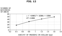
- FIG. 12 is a graph showing the number of rotations of a drum required until rotational initial noise disappears according to the degree of deformation of a roller.
- FIG. 10 a result measuring a time taken until rotational initial noise does not occur by varying the amount of pressing on the roller 30 to 0.4mm, 0.8mm, 1.2mm, and 1.6mm, and the rotation velocity of the drum motor 125 to 1600RPM, 2000RPM, and 2400RPM is shown.
- the times taken until rotational initial noise does not occur differ for each rotation velocity of the drum motor 125 and each amount of pressing on the roller 30.
- R M denotes the rotation velocity (a revolution per minute: an RPM) of the drum motor 125
- T denotes the time s taken until the rotational initial noise does not occur
- P denotes the pulley ratio of the drum motor 125 and the drum 20.
- Equation 1 The results calculated by Equation 1 are shown in the table of FIG. 11 and in the graph of FIG. 12 .
- FIG. 11 it can be seen that when the amount of pressing on the roller 30 is 0.4 mm, the number of rotations of the drum 20 required to eliminate the rotational initial noise is included in a range of 17 to 19 (the average: 18), regardless of whether the rotation velocity of the drum motor 125 is 1600 RPM, 2000 RPM, or 2400 RPM, with a very small fluctuation.
- the number of rotations on the drum 20 required to eliminate the rotational initial noise is included in a range of from 31 to 32 (the average: 31), regardless of whether the rotation velocity of the drum motor 125 is 1600 RPM, 2000 RPM, or 2400 RPM, with a very small fluctuation.
- the number of rotations on the drum 20 required to eliminate the rotational initial noise is included in a range of from 31 to 32 (the average: 31), regardless of whether the rotation velocity of the drum motor 125 is 1600 RPM, 2000 RPM, or 2400 RPM, with a very small fluctuation.
- the number of rotations on the drum 20 required to eliminate the rotational initial noise is included in a range of from 40 to 42 (the average: 41), regardless of whether the rotation velocity of the drum motor 125 is 1600 RPM, 2000 RPM, or 2400 RPM, with a very small fluctuation.
- the number of rotations on the drum 20 required to eliminate the rotational initial noise is included in a range of from 47 to 50 (the average: 49), regardless of whether the rotation velocity of the drum motor 125 is 1600 RPM, 2000 RPM, or 2400 RPM, with a very small fluctuation.
- the shape of the roller 30 returns to the original state only by rotating the roller 30 by a predetermined number that is determined according to the degree of deformation of the roller 30.
- the average values shown in the table of FIG. 11 may be plotted on a graph as shown in FIG. 12 . Referring to FIG. 12 together, it can be seen that the number of rotations of the drum 20 required to restore the shape of the roller 30 increases as the degree of deformation of the roller 30 increases.
- FIG. 13 is a table showing an optimal rotation velocity of a motor according to an ambient temperature and a non-use time
- FIG. 14 is a table showing an optimal rotation time of a motor according to an ambient temperature and a non-use time.
- the controller 110 may store tables representing the optimal operating time of the motor according to the ambient temperature and the non-use time as shown in FIGS. 13 and 14 , and determine the first rotation velocity and the first rotation time of the drum motor 125 based on the stored tables.
- the generated relational expression may be stored, and the controller 110 may determine the first rotation velocity and the first rotation time the drum motor 125 based on the stored relational expression.
- the controller 110 may store a deep learning model generated based on the data shown in FIGS. 13 and 14 and use the stored deep learning model to determine the first rotation velocity and the first rotation time of the drum motor 125.
- FIG. 15 is a flowchart showing a method of controlling a dryer according to an embodiment
- FIG. 16 is a flowchart a method of controlling a dryer according to an embodiment, specifically showing a noise reduction cycle.
- the method of controlling the dryer 1 according to the embodiment may be executed by the dryer 1 according to the above-described embodiment. Therefore, details of the dryer 1 described above may be applied to the method of controlling the dryer according to the embodiment unless stated otherwise, and details of the method of controlling the dryer described below may also be applied to the dryer 1 according to the embodiment unless stated otherwise.
- the dryer 1 is assumed as being at an On state.
- the controller 110 may perform a noise reduction cycle for reducing noise caused by deformation of the roller (1200), and upon the noise reduction cycle being completed, perform the selected rotation cycle (1300).
- the rotation cycle may refer to a cycle including rotations of the drum 20, such as a drying cycle or a dusting function cycle.
- the at least one roller 30 that supports the drum 20 and rotates together with the drum 20 during rotation of the drum 20 has a surface formed of a rubber material. Therefore, while the drum 20 is in a stationary state, the surface of the at least one roller 30 may be deformed by the pressure received by supporting the drum 20, and when the drum 20 rotates again in a state in which the at least one roller 30 is deformed, noise may occur due to friction between the drum 20 and the deformed roller 30.
- a noise reduction cycle is performed before starting a rotation cycle including rotations of the drum 20, to restore the shape of the at least one roller 30 without generating noise.
- the controller 110 may calculate a non-use time of the dryer 1 to perform the noise reduction cycle (1210).
- the controller 110 may calculate the non-use time of the dryer 1 based on the time gap between a time at which the cycle ends last and a time at which the noise reduction cycle starts or a current time.
- the non-use time of the dryer 1 may refer to a non-rotation time of the drum 20, that is, a time for which the drum 20 stops. Therefore, the controller 110 may determine the non-use time of the dryer 1 based on the time gap between the time at which the rotation cycle ends last, that is, at which the rotation of the drum 20 ends last, and the time at which the noise reduction cycle starts or the current time.
- the controller 110 may determine the first rotation velocity and the first rotation time of the motor based on the non-use time of the dryer 1 (1220).
- data regarding the optimal rotation velocity and the optimal rotation time of the motor according to the non-use time of the dryer 1 may be stored in the controller 110.
- the optimal rotation velocity of the motor according to the non-use time of the dryer 1 may indicate the maximum RPM of the drum motor 125, at which rotational initial noise does not occur, when the drum 20, which has not been used for a time corresponding to the non-use time, is rotated again.
- the optimal rotation time of the motor according to the non-use time of the dryer 1 may indicate the time required to restore the original shape of the roller 30 when the drum 20, which has not been used for a time corresponding to the non-use time, is rotated at the above-described optimal rotation velocity of the drum motor 125.
- the rotation velocity and the rotation time of the motor required to restore the shape of the roller 30 formed of rubber may be affected by the temperature of the surrounding of the roller 30. Accordingly, data on the optimal rotation velocity and the optimal rotation time of the motor according to the non-use time of the dryer 1 may be obtained and stored for each ambient temperature.
- the controller 110 may, in response to a rotation cycle being selected, obtain data on the temperature of the surrounding of the roller 30 from the sensor module 130.
- the data measured by the sensor module 130 may be data obtained by measuring the temperature of a space in which the dryer 1 is located, or may be data measured by a temperature sensor provided at a surrounding of the roller 30 inside the dryer 1.
- the controller 110 may obtain data on the temperature of the surrounding of the roller 30 from the outside.
- the dryer 1 may further include a communication module that communicates with an external device, may obtain temperature-related data from other home appliances in the house through the communication module, and may also obtain temperature-related data from an external server that provides weather information.
- the controller 110 may determine the first rotation velocity and the first rotation time of the motor based on the ambient temperature of the roller 30 and the non-use time of the dryer 1.
- the controller 110 may control the motor driver 180 based on the first rotation velocity and the first rotation time (1230), to rotate the drum motor 125 at the first rotation velocity for the first rotation time.
- the controller 110 Upon the first rotation time elapsing (YES in operation 1240), the controller 110 performs the rotation cycle selected by the user (1300). Alternatively, the controller 110 may perform the rotation cycle when a predetermined time further elapses upon the first rotation time elapsing.
- the selected rotation cycle may be a drying cycle or a dusting cycle
- a weight sensing cycle for detecting the weight of a laundry may be performed before the rotation cycle in order to optimally perform the rotation cycle.
- the weight sensing cycle may be performed by rotating the drum 20 at a predetermined velocity, and in this case, the velocity of rotating the drum 20 in the weight sensing cycle may be higher than the velocity of rotating the drum 20 in the noise reduction cycle.
- the cycle may proceed without generating rotational initial noise.
- the method of controlling the dryer described above may be stored in a recording medium in which instructions executable by a computer are stored. That is, instructions for performing the method of controlling the dryer may be stored in a recording medium.
- the instructions may be stored in the form of program code and, when executed by a processor, may perform the operations of the disclosed embodiments.
- the recording medium may be embodied as a computer-readable recording medium.
- the recording medium is a non-transitory computer-readable medium that stores data non-temporarily.
- the computer-readable recording medium includes all kinds of recording media in which instructions which may be decoded by a computer are stored, for example, a Read Only Memory (ROM), a Random Access Memory (RAM), a magnetic tape, a magnetic disk, a flash memory, an optical data storage device, and the like.
- ROM Read Only Memory
- RAM Random Access Memory
- magnetic tape a magnetic tape
- magnetic disk a magnetic disk
- flash memory an optical data storage device
Landscapes
- Engineering & Computer Science (AREA)
- Textile Engineering (AREA)
- Detail Structures Of Washing Machines And Dryers (AREA)
- Control Of Washing Machine And Dryer (AREA)
Applications Claiming Priority (2)
| Application Number | Priority Date | Filing Date | Title |
|---|---|---|---|
| KR1020220070949A KR20230170456A (ko) | 2022-06-10 | 2022-06-10 | 건조기 및 그 제어 방법 |
| PCT/KR2023/003281 WO2023239020A1 (ko) | 2022-06-10 | 2023-03-10 | 건조기 및 그 제어 방법 |
Publications (2)
| Publication Number | Publication Date |
|---|---|
| EP4459037A1 true EP4459037A1 (de) | 2024-11-06 |
| EP4459037A4 EP4459037A4 (de) | 2025-04-30 |
Family
ID=89078263
Family Applications (1)
| Application Number | Title | Priority Date | Filing Date |
|---|---|---|---|
| EP23819959.0A Pending EP4459037A4 (de) | 2022-06-10 | 2023-03-10 | Trockner und verfahren zur steuerung davon |
Country Status (3)
| Country | Link |
|---|---|
| US (1) | US12624497B2 (de) |
| EP (1) | EP4459037A4 (de) |
| CN (1) | CN118715348A (de) |
Families Citing this family (1)
| Publication number | Priority date | Publication date | Assignee | Title |
|---|---|---|---|---|
| EP4172400B1 (de) * | 2020-06-24 | 2026-03-04 | Lg Electronics Inc. | Wäschebehandlungsvorrichtung |
Family Cites Families (24)
| Publication number | Priority date | Publication date | Assignee | Title |
|---|---|---|---|---|
| US5887456A (en) * | 1995-08-30 | 1999-03-30 | Sharp Kabushiki Kaisha | Drum type drying/washing machine |
| JPH11276757A (ja) | 1998-03-30 | 1999-10-12 | Nippon Kentetsu Co Ltd | 洗濯乾燥機 |
| JP2000237491A (ja) | 1999-02-24 | 2000-09-05 | Toshiba Corp | 洗濯機の槽体吊持装置 |
| KR101073508B1 (ko) * | 2003-11-17 | 2011-10-17 | 삼성전자주식회사 | 의류 건조기 |
| KR100640846B1 (ko) | 2005-10-10 | 2006-11-02 | 엘지전자 주식회사 | 건조기 |
| KR20070039746A (ko) * | 2005-10-10 | 2007-04-13 | 엘지전자 주식회사 | 건조기 |
| KR100692582B1 (ko) | 2006-03-24 | 2007-03-14 | 주식회사 대우일렉트로닉스 | 드럼 세탁기 및 드럼 세탁기 건조방법 |
| KR100856305B1 (ko) | 2006-12-21 | 2008-09-03 | 주식회사 포스코 | 저소음용 롤러장치 |
| JP4674601B2 (ja) | 2007-10-18 | 2011-04-20 | パナソニック株式会社 | ドラム式洗濯機 |
| WO2009061325A1 (en) * | 2007-11-09 | 2009-05-14 | Advanced Elastomer Systems, L.P. | Low noise thermoplastic vulcanizate (tpv) support roller |
| KR100964695B1 (ko) * | 2008-01-03 | 2010-06-21 | 엘지전자 주식회사 | 건조기 |
| KR101611270B1 (ko) | 2009-03-19 | 2016-04-11 | 엘지전자 주식회사 | 무게감지장치를 갖는 건조기 및 이를 이용한 건조기제어방법 |
| JP2013094325A (ja) | 2011-10-31 | 2013-05-20 | Samsung Yokohama Research Institute Co Ltd | 乾燥機 |
| KR101579655B1 (ko) | 2013-01-21 | 2015-12-22 | 가부시끼가이샤 도시바 | 의류 건조기 및 컴프레서 구동장치 |
| EP3124689B1 (de) * | 2015-07-27 | 2018-03-07 | Electrolux Appliances Aktiebolag | Verfahren zum betreiben eines wärmepumpentrockners |
| US10731289B2 (en) | 2017-10-26 | 2020-08-04 | Samsung Electronics Co., Ltd. | Clothes dryer and method for performing sterilization course thereof |
| KR102504577B1 (ko) | 2017-10-26 | 2023-03-02 | 삼성전자주식회사 | 의류 건조기 및 그의 살균 행정 수행 방법 |
| KR102408516B1 (ko) | 2017-11-20 | 2022-06-13 | 엘지전자 주식회사 | 건조기의 제어방법 |
| KR102490844B1 (ko) | 2017-11-20 | 2023-01-25 | 엘지전자 주식회사 | 건조기의 제어 방법 |
| CN110004679B (zh) | 2018-01-05 | 2023-05-23 | 青岛海尔洗衣机有限公司 | 一种静音烘干方法及干衣机 |
| JP7245725B2 (ja) | 2019-06-07 | 2023-03-24 | 日立グローバルライフソリューションズ株式会社 | 洗濯機および洗濯機の異常診断方法 |
| CN112481976B (zh) | 2019-08-20 | 2024-05-03 | 青岛海尔洗衣机有限公司 | 一种干衣机的控制方法 |
| KR20210090415A (ko) | 2020-01-10 | 2021-07-20 | 엘지전자 주식회사 | 세탁물 처리장치 및 그 제어방법 |
| KR102835575B1 (ko) | 2020-09-10 | 2025-07-18 | 엘지전자 주식회사 | 세탁물 건조기 |
-
2023
- 2023-03-10 EP EP23819959.0A patent/EP4459037A4/de active Pending
- 2023-03-10 CN CN202380022476.2A patent/CN118715348A/zh active Pending
- 2023-03-14 US US18/183,600 patent/US12624497B2/en active Active
Also Published As
| Publication number | Publication date |
|---|---|
| CN118715348A (zh) | 2024-09-27 |
| US12624497B2 (en) | 2026-05-12 |
| EP4459037A4 (de) | 2025-04-30 |
| US20230399792A1 (en) | 2023-12-14 |
Similar Documents
| Publication | Publication Date | Title |
|---|---|---|
| EP2935687B1 (de) | Verfahren zur steuerung eines wäschetrockners und entsprechender wäschetrockner | |
| US10731289B2 (en) | Clothes dryer and method for performing sterilization course thereof | |
| US12305320B2 (en) | Control method of clothes dryer | |
| EP2746457A1 (de) | Verfahren zur Steuerung eines Wärmepumpensystems für einen Wäschetrockner und entsprechender Wäschetrockner | |
| US20220325463A1 (en) | Dryer and control method therefor | |
| US10544542B2 (en) | Control method for laundry treating apparatus | |
| US20190390395A1 (en) | Dryer and drying method thereof | |
| CN115323738B (zh) | 确定运行参数的方法、衣物处理设备及存储介质 | |
| KR20210087388A (ko) | 건조기 및 그 제어 방법 | |
| US12624497B2 (en) | Dryer and method of controlling the same | |
| CN114941236A (zh) | 干衣机的控制方法、控制装置、存储介质和干衣机 | |
| CN105189850B (zh) | 干燥机 | |
| KR20230170456A (ko) | 건조기 및 그 제어 방법 | |
| KR20230115116A (ko) | 의류 건조기 및 그 제어 방법 | |
| KR20170068820A (ko) | 건조기, 및 그 제어방법 | |
| KR102455222B1 (ko) | 건조기 및 그 제어방법 | |
| CN117090031A (zh) | 用于运行衣物护理器具的方法和设备 | |
| KR102811157B1 (ko) | 건조기 및 그 제어방법 | |
| KR20240122249A (ko) | 건조기 및 그 제어 방법 | |
| KR20250028091A (ko) | 의류 건조기 및 그 제어 방법 | |
| CN118103563A (zh) | 干衣机及其控制方法 | |
| KR20250128070A (ko) | 건조기 및 그 동작 방법 | |
| KR20260027484A (ko) | 터치 감도를 제어하는 건조기, 가전 기기 및 그 방법 | |
| CN103184673B (zh) | 干衣机及其控制方法 |
Legal Events
| Date | Code | Title | Description |
|---|---|---|---|
| STAA | Information on the status of an ep patent application or granted ep patent |
Free format text: STATUS: THE INTERNATIONAL PUBLICATION HAS BEEN MADE |
|
| PUAI | Public reference made under article 153(3) epc to a published international application that has entered the european phase |
Free format text: ORIGINAL CODE: 0009012 |
|
| STAA | Information on the status of an ep patent application or granted ep patent |
Free format text: STATUS: REQUEST FOR EXAMINATION WAS MADE |
|
| 17P | Request for examination filed |
Effective date: 20240729 |
|
| AK | Designated contracting states |
Kind code of ref document: A1 Designated state(s): AL AT BE BG CH CY CZ DE DK EE ES FI FR GB GR HR HU IE IS IT LI LT LU LV MC ME MK MT NL NO PL PT RO RS SE SI SK SM TR |
|
| A4 | Supplementary search report drawn up and despatched |
Effective date: 20250328 |
|
| RIC1 | Information provided on ipc code assigned before grant |
Ipc: D06F 105/52 20200101ALN20250324BHEP Ipc: D06F 105/48 20200101ALN20250324BHEP Ipc: D06F 103/38 20200101ALN20250324BHEP Ipc: D06F 103/24 20200101ALN20250324BHEP Ipc: D06F 103/04 20200101ALN20250324BHEP Ipc: D06F 101/20 20200101ALN20250324BHEP Ipc: D06F 58/06 20060101ALI20250324BHEP Ipc: D06F 58/52 20200101ALI20250324BHEP Ipc: D06F 58/08 20060101AFI20250324BHEP |
|
| DAV | Request for validation of the european patent (deleted) | ||
| DAX | Request for extension of the european patent (deleted) |