EP4456569A1 - Verfahren und vorrichtung zur positionsmessung und zugehörige vorrichtung - Google Patents
Verfahren und vorrichtung zur positionsmessung und zugehörige vorrichtung Download PDFInfo
- Publication number
- EP4456569A1 EP4456569A1 EP22910065.6A EP22910065A EP4456569A1 EP 4456569 A1 EP4456569 A1 EP 4456569A1 EP 22910065 A EP22910065 A EP 22910065A EP 4456569 A1 EP4456569 A1 EP 4456569A1
- Authority
- EP
- European Patent Office
- Prior art keywords
- sensing
- target
- information
- aps
- positioning
- Prior art date
- Legal status (The legal status is an assumption and is not a legal conclusion. Google has not performed a legal analysis and makes no representation as to the accuracy of the status listed.)
- Pending
Links
Images


Classifications
-
- G—PHYSICS
- G01—MEASURING; TESTING
- G01S—RADIO DIRECTION-FINDING; RADIO NAVIGATION; DETERMINING DISTANCE OR VELOCITY BY USE OF RADIO WAVES; LOCATING OR PRESENCE-DETECTING BY USE OF THE REFLECTION OR RERADIATION OF RADIO WAVES; ANALOGOUS ARRANGEMENTS USING OTHER WAVES
- G01S5/00—Position-fixing by co-ordinating two or more direction or position line determinations; Position-fixing by co-ordinating two or more distance determinations
- G01S5/02—Position-fixing by co-ordinating two or more direction or position line determinations; Position-fixing by co-ordinating two or more distance determinations using radio waves
-
- G—PHYSICS
- G01—MEASURING; TESTING
- G01S—RADIO DIRECTION-FINDING; RADIO NAVIGATION; DETERMINING DISTANCE OR VELOCITY BY USE OF RADIO WAVES; LOCATING OR PRESENCE-DETECTING BY USE OF THE REFLECTION OR RERADIATION OF RADIO WAVES; ANALOGOUS ARRANGEMENTS USING OTHER WAVES
- G01S13/00—Systems using the reflection or reradiation of radio waves, e.g. radar systems; Analogous systems using reflection or reradiation of waves whose nature or wavelength is irrelevant or unspecified
- G01S13/02—Systems using reflection of radio waves, e.g. primary radar systems; Analogous systems
- G01S13/06—Systems determining position data of a target
- G01S13/42—Simultaneous measurement of distance and other co-ordinates
- G01S13/422—Simultaneous measurement of distance and other co-ordinates sequential lobing, e.g. conical scan
-
- G—PHYSICS
- G01—MEASURING; TESTING
- G01S—RADIO DIRECTION-FINDING; RADIO NAVIGATION; DETERMINING DISTANCE OR VELOCITY BY USE OF RADIO WAVES; LOCATING OR PRESENCE-DETECTING BY USE OF THE REFLECTION OR RERADIATION OF RADIO WAVES; ANALOGOUS ARRANGEMENTS USING OTHER WAVES
- G01S13/00—Systems using the reflection or reradiation of radio waves, e.g. radar systems; Analogous systems using reflection or reradiation of waves whose nature or wavelength is irrelevant or unspecified
- G01S13/02—Systems using reflection of radio waves, e.g. primary radar systems; Analogous systems
- G01S13/06—Systems determining position data of a target
- G01S13/42—Simultaneous measurement of distance and other co-ordinates
- G01S13/426—Scanning radar, e.g. 3D radar
-
- G—PHYSICS
- G01—MEASURING; TESTING
- G01S—RADIO DIRECTION-FINDING; RADIO NAVIGATION; DETERMINING DISTANCE OR VELOCITY BY USE OF RADIO WAVES; LOCATING OR PRESENCE-DETECTING BY USE OF THE REFLECTION OR RERADIATION OF RADIO WAVES; ANALOGOUS ARRANGEMENTS USING OTHER WAVES
- G01S13/00—Systems using the reflection or reradiation of radio waves, e.g. radar systems; Analogous systems using reflection or reradiation of waves whose nature or wavelength is irrelevant or unspecified
- G01S13/02—Systems using reflection of radio waves, e.g. primary radar systems; Analogous systems
- G01S13/50—Systems of measurement based on relative movement of target
- G01S13/52—Discriminating between fixed and moving objects or between objects moving at different speeds
-
- G—PHYSICS
- G01—MEASURING; TESTING
- G01S—RADIO DIRECTION-FINDING; RADIO NAVIGATION; DETERMINING DISTANCE OR VELOCITY BY USE OF RADIO WAVES; LOCATING OR PRESENCE-DETECTING BY USE OF THE REFLECTION OR RERADIATION OF RADIO WAVES; ANALOGOUS ARRANGEMENTS USING OTHER WAVES
- G01S13/00—Systems using the reflection or reradiation of radio waves, e.g. radar systems; Analogous systems using reflection or reradiation of waves whose nature or wavelength is irrelevant or unspecified
- G01S13/86—Combinations of radar systems with non-radar systems, e.g. sonar, direction finder
-
- G—PHYSICS
- G01—MEASURING; TESTING
- G01S—RADIO DIRECTION-FINDING; RADIO NAVIGATION; DETERMINING DISTANCE OR VELOCITY BY USE OF RADIO WAVES; LOCATING OR PRESENCE-DETECTING BY USE OF THE REFLECTION OR RERADIATION OF RADIO WAVES; ANALOGOUS ARRANGEMENTS USING OTHER WAVES
- G01S13/00—Systems using the reflection or reradiation of radio waves, e.g. radar systems; Analogous systems using reflection or reradiation of waves whose nature or wavelength is irrelevant or unspecified
- G01S13/87—Combinations of radar systems, e.g. primary radar and secondary radar
- G01S13/878—Combination of several spaced transmitters or receivers of known location for determining the position of a transponder or a reflector
-
- G—PHYSICS
- G01—MEASURING; TESTING
- G01S—RADIO DIRECTION-FINDING; RADIO NAVIGATION; DETERMINING DISTANCE OR VELOCITY BY USE OF RADIO WAVES; LOCATING OR PRESENCE-DETECTING BY USE OF THE REFLECTION OR RERADIATION OF RADIO WAVES; ANALOGOUS ARRANGEMENTS USING OTHER WAVES
- G01S5/00—Position-fixing by co-ordinating two or more direction or position line determinations; Position-fixing by co-ordinating two or more distance determinations
- G01S5/02—Position-fixing by co-ordinating two or more direction or position line determinations; Position-fixing by co-ordinating two or more distance determinations using radio waves
- G01S5/0273—Position-fixing by co-ordinating two or more direction or position line determinations; Position-fixing by co-ordinating two or more distance determinations using radio waves using multipath or indirect path propagation signals in position determination
-
- G—PHYSICS
- G01—MEASURING; TESTING
- G01S—RADIO DIRECTION-FINDING; RADIO NAVIGATION; DETERMINING DISTANCE OR VELOCITY BY USE OF RADIO WAVES; LOCATING OR PRESENCE-DETECTING BY USE OF THE REFLECTION OR RERADIATION OF RADIO WAVES; ANALOGOUS ARRANGEMENTS USING OTHER WAVES
- G01S7/00—Details of systems according to groups G01S13/00, G01S15/00, G01S17/00
- G01S7/003—Transmission of data between radar, sonar or lidar systems and remote stations
- G01S7/006—Transmission of data between radar, sonar or lidar systems and remote stations using shared front-end circuitry, e.g. antennas
-
- H—ELECTRICITY
- H04—ELECTRIC COMMUNICATION TECHNIQUE
- H04W—WIRELESS COMMUNICATION NETWORKS
- H04W4/00—Services specially adapted for wireless communication networks; Facilities therefor
- H04W4/02—Services making use of location information
-
- H—ELECTRICITY
- H04—ELECTRIC COMMUNICATION TECHNIQUE
- H04W—WIRELESS COMMUNICATION NETWORKS
- H04W4/00—Services specially adapted for wireless communication networks; Facilities therefor
- H04W4/02—Services making use of location information
- H04W4/023—Services making use of location information using mutual or relative location information between multiple location based services [LBS] targets or of distance thresholds
-
- H—ELECTRICITY
- H04—ELECTRIC COMMUNICATION TECHNIQUE
- H04W—WIRELESS COMMUNICATION NETWORKS
- H04W4/00—Services specially adapted for wireless communication networks; Facilities therefor
- H04W4/02—Services making use of location information
- H04W4/025—Services making use of location information using location based information parameters
- H04W4/026—Services making use of location information using location based information parameters using orientation information, e.g. compass
-
- H—ELECTRICITY
- H04—ELECTRIC COMMUNICATION TECHNIQUE
- H04W—WIRELESS COMMUNICATION NETWORKS
- H04W64/00—Locating users or terminals or network equipment for network management purposes, e.g. mobility management
-
- Y—GENERAL TAGGING OF NEW TECHNOLOGICAL DEVELOPMENTS; GENERAL TAGGING OF CROSS-SECTIONAL TECHNOLOGIES SPANNING OVER SEVERAL SECTIONS OF THE IPC; TECHNICAL SUBJECTS COVERED BY FORMER USPC CROSS-REFERENCE ART COLLECTIONS [XRACs] AND DIGESTS
- Y02—TECHNOLOGIES OR APPLICATIONS FOR MITIGATION OR ADAPTATION AGAINST CLIMATE CHANGE
- Y02D—CLIMATE CHANGE MITIGATION TECHNOLOGIES IN INFORMATION AND COMMUNICATION TECHNOLOGIES [ICT], I.E. INFORMATION AND COMMUNICATION TECHNOLOGIES AIMING AT THE REDUCTION OF THEIR OWN ENERGY USE
- Y02D30/00—Reducing energy consumption in communication networks
- Y02D30/70—Reducing energy consumption in communication networks in wireless communication networks
Definitions
- This application relates to the field of mobile communication technologies, and in particular, to a positioning sensing method and apparatus, and a related device.
- a further communication system further has a wireless sensing capability.
- a communication device may perform sensing measurement in a manner such as active sensing, passive sensing, or interactive sensing.
- a current sensing target on which sensing positioning is performed is usually a terminal, and positioning on a sensing target of a non-terminal is unclear.
- an application range of sensing positioning is relatively narrow.
- Embodiments of this application provide a positioning sensing method and apparatus, and a related device, which are applicable to sensing positioning on a non-terminal, improving an application range of sensing positioning sensing.
- a positioning sensing method including:
- a positioning sensing method including:
- a positioning sensing apparatus including:
- a positioning sensing apparatus including:
- a terminal including a processor and a memory, the memory storing a program or instructions executable on the processor, the program or instructions, when executed by the processor, implementing the steps of the method according to the first aspect.
- a terminal including a processor and a communication interface, where the communication interface is configured to perform azimuth power spectrum APS measurement on a sensing target, to obtain a first APS measurement result of a dynamic reflection path of a first signal, the first APS measurement result being used for determining a positioning result of the sensing target; and the processor is configured to perform a first operation or a second operation based on the first APS measurement result, where the first operation includes sending the first APS measurement result, and the second operation includes determining the positioning result of the sensing target according to the first APS measurement result and at least one received second APS measurement result, the second APS measurement result being an APS measurement result that is of the dynamic reflection path of the first signal and that is obtained by a second sensing device by performing APS measurement on the sensing target.
- a network side device including a processor and a memory, the memory storing a program or instructions executable on the processor, the program or instructions, when executed by the processor, implementing the steps of the method according to the second aspect.
- a network side device including a processor and a communication interface, where the communication interface is configured to receive at least two APS measurement results, each APS measurement result being an APS measurement result that is of a dynamic reflection path of a first signal and that is obtained by a sensing device by performing azimuth power spectrum APS measurement on a sensing target; and the processor is configured to determine a positioning result of the sensing target according to the at least two APS measurement results.
- a readable storage medium storing a program or instructions, the program or instructions, when executed by the processor, implementing the steps of the method according to the first aspect or the steps of the method according to the second aspect.
- a chip including a processor and a communication interface, the communication interface being coupled to the processor, and the processor being configured to run a program or instructions to implement the method according to the first aspect or the method according to the second aspect.
- a computer program product is provided, the computer program product being stored in a non-transient readable storage medium, and the computer program product being executed by at least one processor to implement the method according to the first aspect or the method according to the second aspect.
- azimuth power spectrum APS measurement is performed on a sensing target to obtain a first APS measurement result of a dynamic reflection path of a first signal, the first APS measurement result being used for determining a positioning result of the sensing target; and a first operation or a second operation is performed based on the first APS measurement result.
- at least two sensing devices jointly obtain an APS measurement result of the dynamic reflection path of the first signal to determine the positioning result of the sensing target, so that the sensing target can implement positioning without having a function of receiving and sending signals, thereby improving an application range of sensing positioning.
- first”, second, and so on are intended to distinguish similar objects but do not necessarily indicate a specific order or sequence. It is to be understood that the term used in such a way is interchangeable in proper circumstances, so that the embodiments of this application can be implemented in other sequences than the sequence illustrated or described herein.
- the objects distinguished by “first”, “second”, and the like are usually of one type, and a quantity of objects is not limited, for example, there may be one or more first objects.
- “and/or” used in the specification and the claims represents at least one of the connected objects, and a character “/" in this specification generally indicates an "or” relationship between the associated obj ects.
- LTE long term evolution
- LTE-Advanced LTE-advanced
- LTE-A Long term evolution
- CDMA code division multiple access
- time division multiple access time division multiple access
- FDMA frequency division multiple access
- OFDMA orthogonal frequency division multiple access
- SC-FDMA single-carrier frequency-division multiple access
- system and “network” are usually interchangeably used, and the technology described herein can be applied to the systems and radio technologies mentioned above, and can also be applied to other systems and radio technologies.
- technologies are also applicable to applications other than NR system applications, for example, a 6th generation (6th Generation, 6G) communication system, a new radio (new radio, NR) system is exemplarily described in the following descriptions, and the term “NR” is used in most of the following descriptions.
- 6G 6th generation
- NR new radio
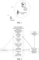
- FIG. 1 shows a block diagram of a wireless communication system to which an embodiment of this application is applicable.
- the communication system includes a terminal 11 and a network side device 12.
- the terminal 11 may be a terminal side device such as a mobile phone, a tablet personal computer (tablet personal computer), a laptop computer (laptop computer) or notebook computer, a personal digital assistant (personal digital assistant, PDA), a palmtop computer, a notebook, an ultra-mobile personal computer (ultra-mobile personal computer, UMPC), a mobile Internet device (mobile Internet device, MID), an augmented reality (augmented reality, AR)/virtual reality (virtual reality, VR) device, a robot, a wearable device (a wearable device), a vehicle user equipment (vehicle user equipment, VUE), a pedestrian user equipment (pedestrian user equipment, PUE), a smart household (which is a household device having a wireless communication function, for example, a refrigerator, a television, a washing machine, or furniture), a game console, a personal
- the wearable device includes: a smart watch, a smart bracelet, a smart headset, smart glasses, smart jewelry (a smart bangle, a smart chain bracelet, a smart ring, a smart necklace, a smart ankle bangle, a smart anklet, or the like), a smart wristband, smart clothing, and the like.
- the network side device 12 may include an access network device or a core network device.
- the access network device 12 may also be referred to as a radio access network device, a radio access network (radio access network, RAN), a radio access network function, or a radio access network unit.
- the access network device 12 may include a base station, a wireless local area network (wireless local area network, WLAN) access point, a wireless fidelity (wireless fidelity, Wi-Fi) node, or the like.
- the base station may be referred to as a node B, an evolved node B (evolved node B, eNB), an access point, a base transceiver station (base transceiver station, BTS), a radio base station, a radio transceiver, a basic service set (basic service set, BSS), an extended service set (extended service set, ESS), a home node B, a home evolved node B, a transmitting receiving point (transmitting receiving point, TRP), or another suitable term in the field.
- the base station is not limited to a specific technical term as long as the same technical effect is achieved. It is to be noted that, in the embodiments of this application, the base station in the NR system is only used as an example for description, but a specific type of the base station is not limited.
- the core network device may include, but not limited to at least one of the following: a core network node, a core network function, a mobility management entity (mobility management entity, MME), an access and mobility management function (access and mobility management function, AMF), a session management function (session management function, SMF), a user plane function (user plane function, UPF), a policy control function (policy control function, PCF), a policy and charging rules function (policy and charging rules function, PCRF), an edge application server discovery function (edge application server discovery function, EASDF), a unified data management (unified data management, UDM), a unified data repository (unified data repository, UDR), a home subscriber server (home subscriber server, HSS), centralized network configuration (centralized network configuration, CNC), a network repository function (network repository function, NRF), a network exposure function (network exposure function, NEF), a local NEF (local NEF, or L-NEF), a binding support function (binding support function, BSF), an application function (application function
- Accurate and real-time position information is an important requirement for various new network services, for example, an emergency service, Internet of Vehicles device, and industrial Internet of Things (industrial Internet of Things, IIoT).
- the positioning technology has been researched for many years.
- a position of a device may be estimated by using measuring a cellular radio signal through a wireless device.
- researchers have become increasingly interested in positioning by using a cellular technology due to expectations for higher positioning precision in an NR network and emergence of more new use cases.
- Positioning solutions usually depends on a time-based technology, an angle-based technology, or a mixed technology.
- a 5th generation (5th generation, 5G) positioning architecture is based on an LTE positioning architecture, and in the positioning architecture, additional modification is performed after a new logical node is introduced in a 5G core (5G core, 5GC).
- the architecture is suitable for positioning a terminal accessed by an NR gNB transmission reception point (transmission reception point, TRP) or a transmission point (transmission point, TP) of an enhanced evolved universal terrestrial radio access network (evolved universal terrestrial radio access network, E-UTRAN) (that is, an LTE ng-eNB).
- TRP transmission reception point
- TP transmission point
- E-UTRAN enhanced evolved universal terrestrial radio access network
- the gNB (gNB-CU)/ng-eNB exchanges necessary positioning and measurement information by using a new radio positioning protocol annex (new radio positioning protocol annex, NRPPa) protocol and a location management function (location management function, LMF) in the 5GC.
- a new radio positioning protocol annex new radio positioning protocol annex, NRPPa
- a location management function location management function, LMF
- LTE LTE positioning protocol
- LPP LTE positioning protocol
- LPP LTE positioning protocol
- the terminal receives, through an NR-Uu or LTE-Uu interface, necessary wireless configuration information from an NG-RAN node in a manner of radio resource control (radio resource control, RRC).
- RRC radio resource control
- the LPP is reused in NR, and the 4th Generation (4th Generation, 4G) and 5G may be expanded in a common protocol.
- Both the NRPPa protocol and the LPP are transmitted on a control plane of an NG interface (the next generation control plane (the next generation control plane, NG-C)) through an access and mobility management function (access and mobility management function, AMF).
- 4G is the 4th generation mobile communication system
- 5G is the 5th generation mobile communication system.
- FIG. 3 further shows a function separation architecture of an NG radio access network (NG-RAN) in R16.
- the NG-RAN includes one gNB central unit (central unit, CU) and one or more gNB distributed units (distributed units, DUs), communication may be performed through an F 1 interface, and the gNB-CU may be connected to one or more gNB-DUs that carry a transmission point TP/reception point (reception point, RP)/transmission reception point TRP.
- TP/reception point reception point
- RP transmission reception point
- a positioning method supported in 3GPP R16 includes: a downlink time difference of arrival (downlink time difference of arrival, DL-TDOA) method, an uplink time difference of arrival (uplink time difference of arrival, UL-TDOA) method, a multi-cell round trip time (multi-cell round trip time, Multi-RTT) method, a downlink angle of departure (downlink angle of departure, DL-AOD) method, an uplink angle of arrival (uplink angle of arrival, UL-AOA) method, and an enhanced cell ID (enhanced cell ID, E-CID) method.
- a downlink time difference of arrival downlink time difference of arrival, DL-TDOA
- uplink time difference of arrival uplink time difference of arrival
- UL-TDOA uplink time difference of arrival
- Multi-RTT multi-cell round trip time
- E-CID enhanced cell ID
- the DL-TDOA method and the UL-TDOA method have been applied in an LTE era.
- a down link-positioning reference signal (down link-positioning reference signal, DL-PRS) is used.
- the UE receives DL-PRSs delivered by different cells, measures a reference signal time difference (reference signal time difference, RSTD), and report the RSTD to the LMF.
- the LMF calculates a position of the UE according to known position information of the base station.
- an up link-sounding reference signal up link-sounding reference signal, UL-SRS
- Different cell sites receive a relative time of arrival (relative time of arrival, RTOA) sent by the UE and report the RTOA to the LMF.
- the LMF calculates a position of the UE according to known position information of the base station.
- the Multi-RTT method, the DL-AOD method, and the UL-AOA method are relatively new positioning methods in NR.
- the base station performs downlink transmission on the DL-PRS, and the UE performs uplink transmission on the UL-SRS.
- the base station performs UL-SRS configuration on the UE by using an RRC protocol, and the LMF performs DL-PRS configuration on the UE by using the LPP.
- the UE reports a measurement result to the LMF by using the LPP, and the base station reports estimation on position information of the UE to the LMF by using the NRPPa protocol.
- the base station performs downlink transmission on a DL-PRS beam
- the UE measures corresponding reference signal received power (reference signal received power, RSRP) and reports a measurement result to the LMF by using the LPP
- the base station sends angle information of the DL-PRS beam to the LMF by using the NRPPa protocol.
- RSRP reference signal received power
- a base station TRP reports, to the LMF through an NRPPa, an AOA measurement result and some other configuration information, for example, a TRP coordinate and beam configuration information.
- the LMF calculates an estimation result of the position of the UE based on the information.
- the foregoing methods may be used in combination with another method (or a measurement process corresponding to the another method), to further improve positioning precision.
- the DL-TDOA method is combined with the DL-AOD method
- the UL-TDOA method is combined with the UL-AOA method
- the multi-RTT method is combined with downlink PRS-RSRP measurement, uplink SRS-RSRP measurement, and AOA measurement.
- a DL-PRS resource occupies a plurality of consecutive orthogonal frequency division multiplex (orthogonal frequency division multiplex, OFDM) symbols in time domain, occupies a plurality of consecutive physical resource blocks (physical resource blocks, PRBs) in frequency domain, and supports multiplexing on a plurality of different DL-PRS resources on different subcarriers in a combing manner.
- a DL-PRS sequence is a pseudo-random sequence (Gold sequence), and an initial value of a generation sequence of the DL-PRS sequence is a function of a PRS sequence ID, a slot index, and a symbol index.
- a frequency domain starting PRB and bandwidth of the DL-PRS are configured through a higher layer.
- a granularity of a parameter of starting PRB configuration is one PRB, and a granularity of bandwidth configuration is 4 PRBs.
- a bandwidth range may be configured to be in a range of 24 to 272 PRBs, and all PRS resources in a DL PRS resource set have the same starting PRB and bandwidth. Patterns of a resource element (resource element, RE) of the DL-PRS resource are staggered in the time domain and support periodic transmission.
- RE resource element
- the UL-SRS for positioning and the SRS for communication are similar (a sequence (Zadoff-chu, ZC) is issued based on a communication signal), but are configured separately in a network.
- the UL-SRS for positioning can occupy, from any symbol of an uplink slot, 1, 2, 4, 8, or 12 consecutive OFDM symbols in the time domain, to provide sufficient coverage to ensure that all associated TRPs can be received.
- a quantity of sequence identifiers of the UL-SRS is increased by 64 times a quantity of sequence identifiers of an NR SRS.
- a frequency domain comb configuration of the UL-SRS may be configured as 8, and power that does not include a positioning signal may be borrowed to obtain an increase in power spectral density, to improve a received SINR of an SRS positioning signal.
- the UL-SRS adopts a staggered pattern design to reduce a side lobe value generated by a correlation operation during sequence detection.
- a positioning target (which may also be referred to as a sensing target or a sensing positioning target) needs to have a communication capability, to enable the positioning target to measure a received signal and/or send a signal, so that the TRP, the RP, the TP, and the like that perform positioning on the positioning target determine position information of the positioning target according to a transmission delay, transmission power, and the like with the positioning target.
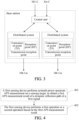
- the embodiments of this application provide a positioning sensing method, which can use a sensing node to perform positioning on a communication device that does not have the communication capability or does not send and receive a signal during positioning. In this way, a vehicle, a pedestrian, or another object/animal can be positioned, thereby expanding a range of the positioning target that can be positioned.
- the positioning sensing method includes the following steps:
- the first operation includes sending the first APS measurement result
- the second operation includes determining the positioning result of the sensing target according to the first APS measurement result and at least one received second APS measurement result, the second APS measurement result being an APS measurement result that is of the dynamic reflection path of the first signal and that is obtained by a second sensing device by performing APS measurement on the sensing target.
- the first sensing device and the second sensing device may be referred to as sensing nodes, where the first sensing device includes a terminal, a network side device, or a dedicated sensing device for performing sensing measurement.
- the first sensing device may be a sending device of the first signal, or may be a receiving device of the first signal.
- the sending device of the first signal may be the terminal, the base station, or the dedicated sensing device.
- the sending device of the first signal is further configured to calculate the positioning result of the sensing target, the sending device is equivalent to a computing device.
- the sending device is a base station, and the base station does not participate in APS sensing measurement
- the first sensing device and the second sensing device may report APS measurement results to the base station, where the reported APS measurement results may be APS measurement results of an entire channel, or may be APS measurement results in a preset angle range.
- a receiving device of the first signal includes the terminal, the network side device, or the dedicated sensing device; or in a case that the first sensing device is a receiving device of the first signal, a sending device of the first signal includes the terminal, the network side device, or the dedicated sensing device.
- the sensing nodes performing sensing measurement may include at least two terminals, or may include at least one base station and at least one terminal, and may further include at least two base stations.
- the first sensing device in a case that the first sensing device is a terminal or a dedicated sensing device, the first sensing device usually does not have a positioning result conversion capability, and in this case, the first sensing device may perform the first operation based on the first APS measurement result, for example, report the first APS measurement result to the base station or the core network device, where the first APS measurement result may be an APS measurement result of the entire channel, or may be an APS measurement result in the preset angle range.
- the first sensing device When the first sensing device is a network side device, for example, a base station, if the first sensing device does not have the positioning result conversion capability, in this case, the first sensing device may perform the first operation based on the first APS measurement result, for example, report the first APS measurement result to the base station or the core network device; and if the first sensing device has the positioning result conversion capability, in this case, the first sensing device may perform the second operation based on the first APS measurement result.
- the core network device may be understood as or replaced with a sensing network function or a sensing network element.
- the at least one second APS measurement result may be obtained by the first sensing device from the corresponding second sensing device, or may be obtained by the first sensing device from the core network device, for example, the second sensing device directly reports an APS measurement result to the core network device.
- the second APS measurement result may be an APS measurement result of the entire channel obtained by performing APS measurement by the second sensing device, or may be an APS measurement result in the preset angle range, thereby reducing a reporting volume, and reducing resource overheads of a system.
- the positioning sensing method in the embodiments of this application is applicable to single positioning or continuous positioning on the sensing target.
- the first sensing device and the second sensing device are sensing devices in a static state.
- the sensing target may be a sensing object in a moving state, and the sensing object may be a UE or may not be a UE.
- the dynamic reflection path of the first signal is a multipath signal received by the sensing device (such as the first sensing device and/or the second sensing device) after the first signal is reflected by the sensing target.
- azimuth power spectrum APS measurement is performed on a sensing target to obtain a first APS measurement result of a dynamic reflection path of a first signal, the first APS measurement result being used for determining a positioning result of the sensing target; and a first operation or a second operation is performed based on the first APS measurement result.
- at least two sensing devices jointly obtain an APS measurement result of the dynamic reflection path of the first signal to determine the positioning result of the sensing target, so that the sensing target can implement positioning without having a function of receiving and sending signals, thereby improving an application range of sensing positioning.
- sensing positioning may be triggered by a sensing demand-side.
- the sensing demand-side may send a sensing requirement to the core network device, to trigger sensing positioning.
- the sensing demand-side may be the terminal, the base station, the sensing target or a third-party application server equivalent to the access network device and the core network device.
- the sensing requirement may include at least one of the following: a sensing region (for example, a sensing region geographical coordinate, a length, a width, and a height of the sensing region, and the like), a sensing target type (for example, a car, a motorcycle, a pedestrian, and the like, which indicates a moving speed range of the sensing target and a wireless signal reflection power level from another perspective), a sensing target UE indication (that is, whether the sensing target is a UE, where if yes, corresponding information such as a UE ID may be attached), sensing/communication-sensing integrated quality of service (quality of service, QoS), a minimum quantity requirement of UEs participating in cooperative sensing, a quantity and density of sensing targets in the sensing region, a sensing result feedback manner (for example, whether feedback is performed in real time or performed after the end of a sensing service or a communication and sensing service), whether continuous positioning or single positioning is performed, a positioning start condition and a continuous positioning end
- the sensing/communication-sensing integrated QoS may include a sensing/communication-sensing integrated service type, a sensing/communication-sensing integrated service priority, a requirement on sensing a resolution, a requirement on sensing an error, a sensing delay budget, a requirement on a maximum sensing range, a requirement on a continuous sensing capability, a requirement on sensing update frequency, and communication QoS (communication QoS of a sensing/communication-sensing integrated service).
- the communication QoS may include a communication delay budget and a false alarm rate.
- a start condition for positioning/continuous positioning may include any one of the following:
- the communication and sensing service may also be referred to as a communication-sensing integrated service, which may specifically include both a communication service and a sensing service.
- the first signal includes any one of the following: a dedicated sensing signal, a communication-sensing integrated signal, an LTE reference signal, and an NR reference signal.
- a downlink reference signal may be a reference signal that is configurable in the time domain, such as an SSB, a CSI-RS, a downlink positioning reference signal (downlink positioning reference signal, DL-PRS), or a phase-tracking reference signal (phase-tracking reference signal, PT-RS).
- An uplink reference signal may be a reference signal that is configurable in the time domain, such as an SRS or a UL-SRS.
- the sending the first APS measurement result includes: sending a plurality of first APS measurement results, the plurality of first APS measurement results being used for determining a movement trajectory of the sensing target, and the plurality of first APS measurement results being APS measurement results obtained by performing APS measurement for a plurality of times.
- a measurement timestamp needs to be recorded and saved, and reported together with the APS measurement result. If conversion of a sensing result (that is, calculation of the positioning result of sensing target) is measured on the core network device, the base station reports an APS measurement result and measurement timestamp information of each UE to the core network device. If measurement is periodically performed (that is, time intervals between two vector measurements are the same, for example, when periodic UL-SRS and DL-PRS are used), a measurement sequence number and a (sensing/communication-sensing integrated signal/NR reference signal) measurement period may be reported instead of the timestamp information.
- the positioning result may be directly determined on the first sensing device.
- the determining the positioning result of the sensing target according to the first APS measurement result and at least one received second APS measurement result includes:
- the determining the positioning result of the sensing target according to the first confidence includes: determining a position coordinate in the target region range with the highest first confidence as a positioning position of a target sensing object.
- the determining a first confidence corresponding to each position coordinate in the target region range according to a target position coordinate, the first APS measurement result, and the second APS measurement result includes:
- second confidences corresponding to the plurality of sensing devices performing APS measurement at the target position are added or multiplied, to obtain the first confidence.
- formula (1) and formula (2) in the following.
- weight coefficients corresponding to the same sensing device at different moments are fixed values, or weight coefficients corresponding to the same sensing device at different moments change in a preset range.
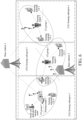
- a quantity of UEs participating in cooperative sensing is 2, and the sensing target is a pedestrian.
- a positioning principle of the positioning sensing method is as follows:
- a UE 1 and a UE 2 may obtain an angle of arrival APS of a downlink signal (or an angle of departure APS of an uplink signal) including a dynamic reflection path caused by the pedestrian.
- the base station may also obtain an angle of departure APS of a downlink signal (or an angle of arrival APS of an uplink reflection signal) including the dynamic reflection path caused by the pedestrian.
- Specific angle estimation may be obtained based on an angle measurement method and an NR beam management idea in a current NR positioning technology, or may be implemented by the UE or the base station by using an own algorithm.
- an azimuth power spectrum may be obtained through fast Fourier transform (fast Fourier transform, FFT), a commonly used spatial filter (such as a Bartlett beamformer (Bartlett beamformer)), minimum variance distortionless response (minimum variance distortionless response, MVDR), multiple signal classification (multiple signal classification, MUSIC), and an improved algorithm thereof.
- Dynamic reflection path identification may be implemented through Doppler spectrum estimation in combination with pattern recognition or machine learning.
- a pedestrian position is an intersection point of extension lines in estimated angle directions with the UE 1, the UE 2, and the base station as starting points.
- the pedestrian position estimated through UE cooperation (or cooperation between the base station and the UE) and sensing is wider region.
- the sensing target is more likely to exist, that is, a measurement confidence is higher.
- a greater quantity of UEs participating in sensing indicates a higher confidence of an overlapping region of regions estimated by each two in all UEs.
- the measure confidence may be the second confidence.
- a channel azimuth power spectrum APS obtained by the UE 1 at a moment t n is P u1 ( ⁇ 1 , t n ), ⁇ 1 ⁇ [ ⁇ min1 , ⁇ max1 ], a channel azimuth power spectrum APS obtained by the UE 2 at the moment t n is P u 2 ( ⁇ 2 , t n ), ⁇ 2 ⁇ [( ⁇ min2 , ⁇ max2 ], and a channel azimuth power spectrum APS obtained by the base station at the moment t n is P 0 ( ⁇ 0 , t n ) ,, ⁇ 0 ⁇ [ ⁇ min0 , ⁇ max0 ], where n is a positive integer.
- the sensing region is divided into a grid map shown in FIG. 5 .
- each grid position may be combined with each UE position to obtain a corresponding angle of arrival (or an angle of departure, which depends on the uplink signal or the downlink signal) of the UE, and the angle is substituted into a UE azimuth power spectrum at a corresponding time to obtain a corresponding power value.
- a confidence C position n corresponding to the pedestrian at the position ( x n , y n ) may be defined as meeting formula (1) or formula (2) in the following:
- C position n ⁇ u 1 t n P u 1 ⁇ n 1 t n ⁇ ⁇ u 2 t n P u 2 ⁇ n 2 t n ;
- C position n ⁇ 0 t n P 0 ⁇ n 0 t n ⁇ ⁇ u 1 t n P u 1 ⁇ n 1 t n ⁇ ⁇ u 2 t n P u 2 ⁇ n 2 t n ;
- ⁇ u 1 ( t n ) represents a weight coefficient of the UE 1 at the moment t n
- ⁇ u 2 ( t n ) represents a weight coefficient of the UE 2 at the moment t n
- ⁇ u 0 ( t n ) represents a weight coefficient of the base station at the moment t n .
- the weight coefficient is in a range of (0, 1] or (0, a non-negative value]. A larger value indicates a higher confidence of sensing measurement on a corresponding sensing device. If continuous positioning sensing is performed, the weight may be a fixed value or a variable in a value range, that is, the weight may be associated with time or a spatial position of the sensing target.
- the computing device divides the search range into several search grid points, and a coordinate of each grid point represents a position coordinate.
- the size of the grid point is comprehensively determined based on a sensing capability of each UE in cooperative sensing (for example, a quantity of antennas during UE angle measurement, bandwidth of a sensing signal, and the like).
- a position of the sensing target is each divided grid point. Based on a position coordinate of the grid point, a position coordinate of the base station participating in sensing and/or a position coordinate of the UE participating in cooperative sensing, an angle value (AOD or AOA) of a dynamic reflection path on a base station side participating in sensing and/or a UE side participating in cooperative sensing when the sensing target is at the grid position.
- the angle value is substituted into equation (1) or equation (2), and a first confidence of the grid point is obtained based on a confidence criterion.
- the calculation node repeats the foregoing calculation on all grid points, and uses a position coordinate of a grid point with a maximum first confidence as an estimated position of the sensing target.
- the weight coefficient may be a fixed value or a dynamic adjusted value in the continuous positioning sensing service or the communication and sensing service.
- the dynamic adjustment may be performed when sensing resources of a cooperative sensing device need to be reconfigured, or the sensing target enters or leaves an optimal sensing range of the cooperative sensing device. Adjustment on the weight coefficient of the cooperative sensing device may be determined by the core network device.
- the determining a target region range includes at least one of the following:
- the first preset rule includes at least one of the following:
- the sensing target is not required to be a UE.
- the first prior information includes at least one of the following:
- the first position may be understood as an initial position, and the initial position of the sensing target may be determined through sensing measurement by a sensing node at the initial position.
- the sensing node at the initial position one of the base station or the cooperative sensing UE
- needs to temporarily occupy more time domain resources that is, it is necessary to increase density, a quantity of repetitions, and a coverage time length of the sensing/communication-sensing integrated signals/reference signals in the time domain
- frequency domain resources that is, it is necessary to increase distribution density and a coverage frequency range of the sensing/communication-sensing integrated signals/reference signals in the frequency domain
- space domain resources that is, it is necessary to increase a quantity of antennas sensing and an aperture of an antenna array.
- the sensing node at the initial position may be determined by the core network device based on sensing capability information reported by each sensing device (or sensing node).
- the sensing node reports the obtained first position to the core network device, and the core network device determines a target region range and notifies the first sensing device of the target region range.
- the sensing node at the initial position may be completed by one or more base stations, or may be completed by one or more terminals, or may be completed by both the base station and the terminal.
- the sensing target is required to be a UE, and the initial position of the sensing target is determined based on the NR positioning method. Whether the sensing target is a UE is indicated in the sensing requirement. When the sensing target is also the UE, the core network device may determine to initiate sensing target positioning to obtain an approximate range of the initial position.
- the sensing target is required to be a UE
- the third position may be understood as the initial position
- the target region range corresponding to the initial position is determined through the GPS.
- the sensing target is not required to be a UE, and the initial position is determined through Bluetooth (Bluetooth) or in a manner such as an ultra wide band (ultra wide band, UWB) technology.
- the target region range is determined jointly by the plurality of rules.
- the method further includes: reporting, by the first sensing device, target information to a computing device, the target information including device information of the first sensing device, the device information of the first sensing device being used by the computing device to determine whether the first sensing device participates in cooperative sensing, and the computing device being a base station that determines to participate in cooperative sensing or a core network device.
- the first sensing device is not a computing device, that is, whether to participate in cooperative sensing is not calculated on the first sensing device.
- the first sensing device needs to report the device information of the first sensing device to the computing device. It may be understood that, reporting by the first sensing device to the computing device may be understood as directly reporting to the computing device or indirectly reporting to the sensing device through an intermediate device. For example, when the first sensing device is a terminal and the first computing device is a core network device, the first sensing device may report the target information to the base station.
- the device participating in cooperative sensing may be understood as a sensing device that sends or receives the first signal.
- the target information further includes device information of at least one sensing device received by the first sensing device, the device information of the sensing device being used by the computing device to determine whether the sensing device participates in cooperative sensing.
- the at least one sensing device may be understood as a device with a sensing function.
- the first sensing device may receive the device information sent by the at least one sensing device and report the device information together with device information of the first sensing device. It is to be noted that, when it is determined that a sensing device other than the first sensing device participates in cooperative sensing and the sensing device performs APS measurement, the sensing device may be understood as a second sensing device.
- the method further includes: determining, by the first sensing device according to received device information of a sensing device, at least some second sensing devices that participate in cooperative sensing.
- the second device participating in cooperative sensing may be completely determined by the first sensing device, or may be partially determined by the core network device and partially determined by the first sensing device. This is not further limited herein.
- a manner in which the first sensing device determines the at least some second sensing devices that participate in cooperative sensing includes any one of the following:
- the device information includes at least one of the following: state information and sensing capability information.
- the state information includes at least one of the following: position information, a position information determining method, motion state information, panel orientation information, panel tilt angle information, communication state information, sensing state information, and beamforming configuration information.
- the core device may first determine a base station participating in sensing, and then the base station participating in sensing broadcast control information carrying a sensing requirement and a UE status information reporting request to the sensing region.
- a UE within coverage of the base station reports device information of the UE.
- the core network device determines a UE participating in cooperative sensing based on the sensing requirement and the device information reported by the UE.
- the base station participating in sensing determines the UE participating in cooperative sensing based on the device information reported by the UE.
- the core network device determines some UEs participating in cooperative sensing based on the device information reported by the UE, and the base station participating in sensing determines some other UEs participating in cooperative sensing based on the device information reported by the UE.
- the UE may be another type of sensing node with the same function, for example, a small cell.
- the base station may report, to the core network device, information about a terminal determining to participate in cooperative sensing.
- the reported information may include at least one of the following: a cooperative sensing UE ID, cooperative sensing UE position information, a method for determining the cooperative sensing UE position information (or equivalently, information indicating accuracy of a UE position), a total quantity of cooperative sensing UEs in the sensing region, and cooperative sensing UE status information.
- the core network device may also initiate a positioning process for this part of UEs to obtain position information of the UEs.
- the positioning may be performed by using the NR positioning method or another method.
- the base station or the UE reports the position information of this part of the UEs, a method for portioning this part of the UE positioning method (or equivalently, information indicating accuracy of a UE portion), and other device information of this part of UEs are reported to the core network device.
- the core network device ultimately determines all UEs participating in cooperative sensing.
- the first APS measurement result is an APS measurement result of an entire channel or an APS measurement result in a preset angle range
- the preset angle range is determined by the first sensing device or indicated by a computing device
- the computing device is a base station that determines to participate in cooperative sensing or a core network device.
- the APS measurement result of the entire channel may be reported, or the APS measurement result in the preset angle range corresponding to the dynamic reflection path of the sensing target may be reported, thereby reducing reporting overheads.
- the preset angle range may be identified from historical APS measurement results and/or dynamic reflection path spectrum peaks.
- the core network device may predict an approximate location range of a current sensing target based on a historical positioning result of continuous positioning, further obtain an approximate range from the sensing target to an angle of arrival (or an angle of departure, depending on whether measurement is uplink or downlink) of each cooperative sensing UE, and deliver a range the angle of arrival (or angle of departure) to each cooperative sensing UE.
- the UE feeds back, based on the result, an APS measurement value in a corresponding angle range to the core network.
- the performing, by a first sensing device, azimuth power spectrum APS measurement on a sensing target, to obtain a first APS measurement result of a dynamic reflection path of a first signal includes at least one of the following:
- Measurement includes the following cases:
- sensing devices may also be grouped, and the sensing device participating in cooperative sensing may be determined through grouping.
- UEs participating in cooperative sensing may be grouped.
- the group may be determined by the core network device. A procedure of determining a base station and a terminal that participating cooperative sensing is described below by using an example in which both the base station and the terminal are used as sensing devices for cooperative sensing.
- the sensing region can be divided into sensing subregions, the sensing subregion is a smaller physical region in the sensing region.
- the division (a position and an area) of the sensing subregion may be determined according to at least one of the following:
- division may also be performed according to a preset default value, for example, division is evenly performed, division is performed based on a historical continuous positioning service division result, or the like.
- two level division may be performed on the sensing subregions, respectively corresponding to division on subregions of the base station and the UE (hereinafter referred to as a base station sensing subregion and a UE sensing subregion respectively).
- Areas of physical regions on which two level division is performed may be different.
- a quantity of base stations is less than that of UEs, but coverage is larger and can support a larger sensing distance. Therefore, a physical range of the base station sensing subregion is generally larger than that of the UE sensing subregion.
- One base station sensing subregion may include one or more UE sensing subregions, and the base station sensing subregion may be physically discontinuous. As shown in FIG.
- a sensing subregion corresponding to a base station 1 is a combined region of a UE sensing subregion 1 and a UE sensing subregion 2, that is, the sensing subregion of the base station 1 includes the UE sensing subregion 1 and the UE sensing subregion 2.
- a sensing subregion of a base station 2 only includes a UE sensing subregion 3.
- base stations participating in sensing are allocated to each base station sensing subregion, and a group of cooperative sensing UEs are allocated to each UE sensing subregion.
- the basis for allocating cooperative sensing UEs to the UE sensing subregion may be at least one of the following: UE position information, UE sensing capability indication information, a UE sensing state indication, and a UE communication state indication in the UE status information.
- One sensing subregion corresponds to one UE group, and a total quantity of cooperative sensing UEs in one UE group is at least 2.
- the basis for allocating base stations participating in sensing to the base station sensing subregion may be at least one of the following: base station position information, base station sensing capability indication information, a base station sensing state indication, and a base station communication state indication in the base station status information.
- the UE group is associated with a sensing base station, the association basis may be at least one of the following: a base station sensing subregion division result, a UE sensing subregion division result, one or more of the base station status information, and one or more of the UE status information.
- a core network device delivers an association result to the base station participating in sensing.
- the core network device delivers the association result to a cooperative sensing UE group.
- the base station can schedule UEs in another neighboring UE group that meets the sensing requirement to perform cooperative sensing in a time division multiplexing (or frequency division multiplexing or code division multiplexing) manner.
- an outermost solid line box represents a sensing region
- a dotted line box represents three divided UE sensing subregions
- an ellipse frame represents different cooperative sensing UE groups.
- a UE sensing subregion 3 For a UE sensing subregion 3, only a UE 5 is available in this region.
- the network may configure a UE 3 into a time division multiplexing sensing mode, that is, on some slots, the UE 3 and another cooperative sensing UE in a UE group 2 perform continuous positioning on a sensing target 2; and on some other nonoverlapping slots, the UE 3 cooperates with the UE 5 in a UE group 3 to perform continuous positioning on a sensing target 3.
- the core network device classifies the regions into sensing blind zones.
- sensing-related parameters may be configured.
- the core network device may send configuration parameter information related to the sensing/communication-sensing integrated signal/NR reference signal to the base station participating in sensing.
- the configuration parameter information of the UE may be transmitted through the core network device by using NAS signaling.
- the core network device may first send the configuration parameter information of the sensing/communication-sensing integrated signal to the base station participating in sensing, and then the base station delivers the information to the UE.
- the configuration parameter information includes at least one of the following: a waveform, a subcarrier spacing, bandwidth, burst (burst) duration, an intra-burst signal time interval, an inter-burst time interval, transmit signal power, a signal format, a signal direction, a time resource, a frequency resource, an antenna/antenna port index, a quantity of antenna/antenna ports, and a quasi co-location (quasi co-location, QCL) relationship.
- a waveform a subcarrier spacing, bandwidth, burst (burst) duration, an intra-burst signal time interval, an inter-burst time interval, transmit signal power, a signal format, a signal direction, a time resource, a frequency resource, an antenna/antenna port index, a quantity of antenna/antenna ports, and a quasi co-location (quasi co-location, QCL) relationship.
- the method further includes: switching, by the first sensing device according to a second preset rule, at least one device that participates in cooperative sensing.
- the second preset rule includes at least one of the following:
- the first preset condition includes at least one of the following:
- the second preset condition includes at least one of the following:
- the at least one device participating in cooperative sensing may be a terminal, or may be a base station, or may be a dedicated sensing device.
- Embodiment 1 Group UEs participating in cooperative sensing and/or switch a base station participating in sensing.
- the target may move during the sensing service, the target may leave a sensing range of an original cooperative sensing UE group.
- the network needs to allocate a new cooperative sensing UE group to the sensing target, or even allocate a new base station participating in sensing.
- the new cooperative sensing UE group may include some UEs in the original cooperative sensing UE group.
- a new cooperative sensing UE group may also be allocated, or the original cooperative sensing UE group may be used, that is, the core network re-associates the cooperative sensing UE and the base station.
- a condition for switching the base station participating in sensing includes at least one of the following:
- a condition for triggering to switch a cooperative sensing UE group may include at least one of the following:
- a process of switching the base stations participating in sensing includes:
- the process of switching the cooperative sensing UE groups includes:
- a continuous positioning sensing service may be triggered, or another positioning sensing process (such as performing continuous positioning based on a sensing node in a manner of self-transmitting and self-receiving a sensing signal, or performing NR continuous positioning, or performing continuous positioning based on GPS/Bluetooth/UWB) may be switched.
- another positioning sensing process such as performing continuous positioning based on a sensing node in a manner of self-transmitting and self-receiving a sensing signal, or performing NR continuous positioning, or performing continuous positioning based on GPS/Bluetooth/UWB
- Embodiment 2 Failure and addition of a cooperative sensing UE.
- the cooperative sensing UE may be unable to continue supporting cooperative sensing due to own reasons of the UE.
- the network needs to perform failure judgment on the cooperative sensing UE and remove a failed cooperative sensing UE. If necessary, it is also necessary to perform UE addition on the current sensing cooperative UE group.
- a condition for triggering cooperative sensing UE failure may include at least one of the following:
- UE addition needs to be performed on the cooperative sensing group.
- the network may also perform UE addition.
- a specific failure and addition process of the cooperative sensing UE includes:
- Embodiment 3 Adjustment on measurement confidences of the cooperative sensing UE and/or the base station.
- the measurement confidence of the cooperative sensing UE is reflected by the weight coefficient in formula (1) or formula (2).
- the measurement confidence of the UE finally integrates accuracy of results.
- the corresponding weight coefficient may be dynamically adjusted to obtain more accurate continuous positioning results.
- available sensing resources of the cooperative sensing UE may change. For example, during the sensing service, the UE obtains more resources (which may also be fewer resources) in time domain (where correspondingly, more symbols may be occupied in the time domain for transmitting sensing/communication-sensing integrated signals/NR reference signal s)/frequency domain (where correspondingly, greater sensing/communication-sensing integrated bandwidth is obtained)/space domain (where correspondingly, more antenna ports/a larger quantity of antennas for sensing/communication-sensing integrated integration). If a sensing capability of the UE changes, a measurement confidence of the UE also needs to be adjusted.
- measurement accuracy of the cooperative sensing UE is related to position accuracy of the cooperative sensing UE. If the cooperative sensing UE updates a position of the UE by using a more accurate positioning method, a measurement confidence of the UE also needs to be adjusted.
- measurement accuracy of the cooperative sensing UE is related to a position of the sensing target.
- a measurement confidence of the UE also needs to be adjusted. For example, for Doppler frequency measurement, when a distance between the sensing target and the base station and each cooperative sensing UE meets a far-field condition, measurement accuracy is higher. For APS measurement, when the sensing target faces a multi-antenna panel of the UE, measurement accuracy is higher.
- the measurement accuracy of the cooperative sensing UE is also related to a signal noise ratio (signal noise ratio, SNR) on a cooperative sensing UE side.
- SNR signal noise ratio
- a measurement confidence of each UE in the cooperative sensing UE group needs to ensure that a confidence of the position of the sensing target is kept in a preset range throughout the continuous positioning.
- a quantity of UEs in the group may change.
- weight coefficients corresponding to all UEs in the group need to be adjusted as a whole.
- adjustment on the measurement confidences may be completed by each sensing node by reporting an updated weight coefficient recommendation value to the core network, or may be autonomously performed by the core network device.
- Embodiment 4 Positioning enhancement.
- a major problem in existing outdoor GPS continuous positioning is that positioning is likely to be blocked by high-rise buildings, resulting in weak GPS signals, which causes low positioning accuracy in some regions or on some road sections, and even inability to perform GPS positioning services.
- the existing 3GPP positioning solution is limited by a large deployment distance of outdoor macro stations, and positioning accuracy is also relatively limited.
- a GPS position before blocking may be used as an initial position to achieve continuous positioning on a sensing target in a region where GPS signals are blocked or coverage is poor. The method is a supplement to existing continuous positioning methods.
- a region in which GPS signals are blocked or coverage is poor is generally considered that there is still sufficiently dense distribution of base stations and UEs.
- the continuous positioning sensing method in this application may be switched.
- GPS positioning information of the sensing target may be used as initial position information of continuous positioning in this method.
- GPS continuous positioning may be switched again. In this method, overall performance of the continuous positioning service is improved.
- the embodiments of this application further provide a positioning sensing method, including the following steps:
- the method before the receiving, by a core network device, at least two APS measurement results, the method further includes:
- a manner in which the core network device determines the sensing device that participates in cooperative sensing includes at least one of the following:
- the device information includes at least one of the following: state information and sensing capability information.
- the state information includes at least one of the following: position information, a position information determining method, motion state information, panel orientation information, panel tilt angle information, communication state information, sensing state information, and beamforming configuration information.
- the method further includes: switching, by the core network device according to a second preset rule, at least one device that participates in cooperative sensing.
- the second preset rule includes at least one of the following:
- the first preset condition includes at least one of the following:
- the second preset condition includes at least one of the following:
- the first signal includes any one of the following: a dedicated sensing signal, a communication-sensing integrated signal, an LTE reference signal, and an NR reference signal.
- the positioning sensing method provided in the embodiments of the present invention is the method performed by the core network device in the embodiment of FIG. 4 , which can implement the steps performed by the core network device and achieve the same technical effect. To avoid repetition, details are not described herein again.
- An execution entity of the positioning sensing method in the embodiments of this application may be a positioning sensing apparatus.
- the positioning sensing apparatus provided in the embodiments of this application is described in the embodiments of this application by using an example in which the positioning sensing apparatus performs the positioning sensing method.
- a positioning sensing apparatus 800 provided in the embodiments of this application includes:
- the first sensing device includes a terminal, a network side device, or a dedicated sensing device for performing sensing measurement.
- a receiving device of the first signal includes the terminal, the network side device, or the dedicated sensing device; or in a case that the first sensing device is a receiving device of the first signal, a sending device of the first signal includes the terminal, the network side device, or the dedicated sensing device.
- the first signal includes any one of the following: a dedicated sensing signal, a communication-sensing integrated signal, an LTE reference signal, and an NR reference signal.
- the sending the first APS measurement result includes: sending a plurality of first APS measurement results, the plurality of first APS measurement results being used for determining a movement trajectory of the sensing target, and the plurality of first AP S measurement results being APS measurement results obtained by performing APS measurement for a plurality of times.
- the second operation performed by the execution module 802 includes:
- the determining the positioning result of the sensing target according to the first confidence includes: determining a position coordinate in the target region range with the highest first confidence as a positioning position of a target sensing object.
- the determining a target region range includes at least one of the following:
- the first preset rule includes at least one of the following:
- the first prior information includes at least one of the following:
- the determining a first confidence corresponding to each position coordinate in the target region range according to a target position coordinate, the first APS measurement result, and the second APS measurement result includes:
- weight coefficients corresponding to the same sensing device at different moments are fixed values, or weight coefficients corresponding to the same sensing device at different moments change in a preset range.
- the positioning sensing apparatus 800 further includes: a first sending module, configured to report target information to a computing device, the target information including device information of the first sensing device, the device information of the first sensing device being used by the computing device to determine whether the first sensing device participates in cooperative sensing, and the computing device being a base station that determines to participate in cooperative sensing or a core network device.
- a first sending module configured to report target information to a computing device, the target information including device information of the first sensing device, the device information of the first sensing device being used by the computing device to determine whether the first sensing device participates in cooperative sensing, and the computing device being a base station that determines to participate in cooperative sensing or a core network device.
- the target information further includes device information of at least one sensing device received by the first sensing device, the device information of the sensing device being used by the computing device to determine whether the sensing device participates in cooperative sensing.
- the positioning sensing apparatus 800 further includes: a second determining module, configured to determine, according to received device information of a sensing device, at least some second sensing devices that participate in cooperative sensing.
- a second determining module configured to determine, according to received device information of a sensing device, at least some second sensing devices that participate in cooperative sensing.
- a manner for determining the at least some second sensing devices that participate in cooperative sensing includes any one of the following:
- the device information includes at least one of the following: state information and sensing capability information.
- the state information includes at least one of the following: position information, a position information determining method, motion state information, panel orientation information, panel tilt angle information, communication state information, sensing state information, and beamforming configuration information.
- the first APS measurement result is an APS measurement result of an entire channel or an APS measurement result in a preset angle range
- the preset angle range is determined by the first sensing device or indicated by a computing device
- the computing device is a base station that determines to participate in cooperative sensing or a core network device.
- the performing, by a first sensing device, azimuth power spectrum APS measurement on a sensing target, to obtain a first APS measurement result of a dynamic reflection path of a first signal includes at least one of the following:
- the positioning sensing apparatus 800 further includes: a switching module, configured to switch, according to a second preset rule, at least one device that participates in cooperative sensing.
- the second preset rule includes at least one of the following:
- the first preset condition includes at least one of the following:
- the second preset condition includes at least one of the following:
- the positioning sensing apparatus 900 includes:
- the receiving module 901 is further configured to receive device information of the sensing device; and the first determining module 902 is further configured to determine, according to the device information, whether the sensing device participates in cooperative sensing.
- a manner for determining the sensing device that participates in cooperative sensing includes at least one of the following:
- the device information includes at least one of the following: state information and sensing capability information.
- the state information includes at least one of the following: position information, a position information determining method, motion state information, panel orientation information, panel tilt angle information, communication state information, sensing state information, and beamforming configuration information.
- the positioning sensing apparatus further includes: a switching module, configured to switch, according to a second preset rule, at least one device that participates in cooperative sensing.
- the second preset rule includes at least one of the following:
- the first preset condition includes at least one of the following:
- the second preset condition includes at least one of the following:
- the first signal includes any one of the following: a dedicated sensing signal, a communication-sensing integrated signal, an LTE reference signal, and an NR reference signal.
- the positioning sensing apparatus in this embodiment of this application may be an electronic device, for example, an electronic device with an operating system, or may be a component in an electronic device, for example, an integrated circuit or a chip.
- the electronic device may be a terminal, or may be another device other than a terminal.
- the terminal may include but is not limited to a type of the terminal 11 listed above, and the another device may be a server, a network attached storage (network attached storage, NAS), or the like. This is not specifically limited in the embodiments of this application.
- the positioning sensing apparatus provided in the embodiments of this application can implement the processes implemented in the method embodiments of FIG. 4 to FIG. 7 and achieve the same technical effect. To avoid repetition, details are not described herein again.
- an embodiment of this application further provides a communication device 1000, including a processor 1001 and a memory 1002, the memory 1002 storing a program or instructions runnable on the processor 1001, for example, the program or instructions, when executed by the processor 1001, implementing the steps of the embodiments of the positioning sensing method, and achieving the same technical effect. To avoid repetition, details are not described herein again.
- An embodiment of this application further provides a terminal, including a processor and a communication interface, where the communication interface is configured to perform azimuth power spectrum APS measurement on a sensing target, to obtain a first APS measurement result of a dynamic reflection path of a first signal, the first APS measurement result being used for determining a positioning result of the sensing target; and the processor is configured to perform a first operation or a second operation based on the first APS measurement result.
- the embodiment of the terminal corresponds to the embodiment of the method of the terminal side. All implementation processes of the method embodiment are applicable to the embodiment of the terminal and can achieve the same technical effects.
- FIG. 11 is a schematic diagram of a hardware structure of a terminal according to an embodiment of this application.
- the terminal 1100 includes, but is not limited to, at least some components such as a radio frequency unit 1101, a network module 1102, an audio output unit 1103, an input unit 1104, a sensor 1105, a display unit 1106, a user input unit 1107, an interface unit 1108, a memory 1109, and a processor 1110.
- the terminal 1100 may further include a power supply (such as a battery) for supplying power to the components.
- a power supply such as a battery
- the power supply may be logically connected to the processor 1110 by using a power management system, thereby implementing functions such as charging, discharging, and power consumption management by using the power management system.
- a terminal structure shown in FIG. 11 does not constitute a limitation to the terminal, and the terminal may include more or fewer components than those shown in the figure, or some components may be combined, or a different component deployment may be used. Details are not described herein again.
- the input unit 1104 may include a graphics processing unit (graphics processing unit, GPU) 11041 and a microphone 11042.
- the graphics processing unit 11041 processes image data of a static picture or a video obtained by an image capturing apparatus (for example, a camera) in a video capturing mode or an image capturing mode.
- the display unit 1106 may include a display panel 11061.
- a display panel 11061 may be configured in a form such as a liquid crystal display or an organic light-emitting diode.
- the user input unit 1107 includes at least one of a touch panel 11071 and another input device 11072.
- the touch panel 11071 is also referred to as a touchscreen.
- the touch panel 11071 may include two parts: a touch detection apparatus and a touch controller.
- the another input device 11072 may include, but is not limited to, a physical keyboard, a functional key (such as a volume control key or a switch key), a track ball, a mouse, and a joystick, and the details will not be described herein again.
- the radio frequency unit 1101 may transmit the data to the processor 1110 for processing.
- the radio frequency unit 1101 may send uplink data to the network side device.
- the radio frequency unit 1101 includes, but is not limited to, an antenna, an amplifier, a transceiver, a coupler, a low noise amplifier, a duplexer, and the like.
- the memory 1109 may be configured to store a software program or instructions and various data.
- the memory 1109 may mainly include a first storage area that stores a program storage or instructions and a second storage area that stores data.
- the first storage area may store an operating system, an application program or instructions required by at least one function (for example, a sound playback function and an image playback function), or the like.
- the memory 1109 may include a volatile memory or a non-volatile memory, or the memory 1109 may include both a volatile memory and a non-volatile memory.
- the non-volatile memory may be a read-only memory (read-only memory, ROM), a programmable ROM (programmable ROM, PROM), an erasable programmable read-only memory (erasable PROM, EPROM), an electrically EPROM (electrically EPROM, EEPROM), or a flash memory.
- ROM read-only memory
- PROM programmable ROM
- EPROM erasable programmable read-only memory
- EPROM erasable programmable read-only memory
- electrically EPROM electrically EPROM
- EEPROM electrically EPROM
- the volatile memory may be a random access memory (random access memory, RAM), a static RAM (static RAM, SRAM), a dynamic RAM (dynamic RAM, DRAM), a synchronous DRAM (synchronous DRAM, SDRAM), a double data rate SDRAM (double data rate SDRAM, DDR SDRAM), an enhanced SDRAM (enhanced SDRAM, ESDRAM), a synch link DRAM (synch link DRAM, SLDRAM), and a direct rambus RAM (direct rambus RAM, DRRAM).
- RAM random access memory
- static RAM static RAM
- SRAM static RAM
- dynamic RAM dynamic RAM
- DRAM dynamic RAM
- SDRAM synchronous DRAM
- SDRAM double data rate SDRAM
- ESDRAM enhanced SDRAM
- synch link DRAM synch link DRAM
- SLDRAM direct rambus RAM
- DRRAM direct rambus RAM
- the processor 1110 may include one or more processing units.
- the processor 1110 integrates an application processor and a modem processor.
- the application processor mainly processes operations involving an operating system, a user interface, an application program, or the like.
- the modem processor mainly processes a wireless communication signal, for example, a baseband processor. It may be understood that the foregoing modem processor may not be integrated into the processor 1110.
- the radio frequency unit 1101 performs azimuth power spectrum APS measurement on a sensing target, to obtain a first APS measurement result of a dynamic reflection path of a first signal, the first APS measurement result being used for determining a positioning result of the sensing target;
- the processor 1110 performs a first operation or a second operation based on the first APS measurement result, where
- the first operation includes sending the first APS measurement result
- the second operation includes determining the positioning result of the sensing target according to the first APS measurement result and at least one received second APS measurement result, the second APS measurement result being an APS measurement result that is of the dynamic reflection path of the first signal and that is obtained by a second sensing device by performing APS measurement on the sensing target.
- azimuth power spectrum APS measurement is performed on a sensing target to obtain a first APS measurement result of a dynamic reflection path of a first signal, the first APS measurement result being used for determining a positioning result of the sensing target; and a first operation or a second operation is performed based on the first APS measurement result.
- at least two sensing devices jointly obtain an APS measurement result of the dynamic reflection path of the first signal to determine the positioning result of the sensing target, so that the sensing target can implement positioning without having a function of receiving and sending signals, thereby improving an application range of sensing positioning.
- An embodiment of this application further provides a network side device, including a processor and a communication interface, where the communication interface is configured to receive at least two APS measurement results, each APS measurement result being an APS measurement result that is of a dynamic reflection path of a first signal and that is obtained by a sensing device by performing azimuth power spectrum APS measurement on a sensing target; and the processor is configured to determine a positioning result of the sensing target according to the at least two APS measurement results.
- the embodiment of the network side device corresponds to the method embodiment of the network side device. All implementation processes of the method embodiment are applicable to the embodiment of the network side device and can achieve the same technical effects.
- the network side device 1200 includes an antenna 1201, a radio frequency apparatus 1202, a baseband apparatus 1203, a processor 1204, and a memory 1205.
- the antenna 1201 is connected to the radio frequency apparatus 1202.
- the radio frequency apparatus 1202 receives information by using the antenna 1201, and sends the received information to the baseband apparatus 1203 for processing.
- the baseband apparatus 1203 processes to-be-processed information, and sends the information to the radio frequency apparatus 1202.
- the radio frequency apparatus 1202 processes received information and sends the information by using the antenna 1201.
- the method performed by the network side device may be implemented in the baseband apparatus 1203.
- the baseband apparatus 1203 includes a baseband processor.
- the baseband apparatus 1203 may include, for example, at least one baseband plate.
- a plurality of chips are arranged on the baseband plate. As shown in FIG. 12 , one of the plurality of chips is, for example, the baseband processor, and is connected to the memory 1205 through a bus interface, to invoke a program in the memory 1205 to perform operations performed by the network side device in the foregoing method embodiment.
- the network side device may further include a network interface 1206.
- the interface is, for example, a common public radio interface (common public radio interface, CPRI).
- the network side device 1200 in this embodiment of the present invention further includes: instructions or a program stored in the memory 1205 and executable on the processor 1204, and the processor 1204 invokes the instructions or program in the memory 1205 to perform the method performed by the modules shown in FIG. 8 or FIG. 9 , and can achieve the same technical effect. To avoid repetition, details are not described herein again.
- an embodiment of this application further provides a network side device.
- the network side device 1300 includes a processor 1301, a network interface 1302, and a memory 1303.
- the network interface 1302 is, for example, a common public radio interface (common public radio interface, CPRI).
- the network side device 1300 in this embodiment of the present invention further includes: instructions or a program stored in the memory 1303 and executable on the processor 1301, and the processor 1301 invokes the instructions or program in the memory 1303 to perform the method performed by the modules shown in FIG. 9 , and can achieve the same technical effect. To avoid repetition, details are not described herein again.
- An embodiment of this application further provides a readable storage medium.
- the readable storage medium may be non-volatile or volatile.
- the readable storage medium stores a program or instructions, the program or instructions, when executed by a processor, implementing the processes of the embodiments of the positioning sensing method, and achieving the same technical effect. To avoid repetition, details are not described herein again.
- the processor is a processor in the terminal in the foregoing embodiments.
- the readable storage medium includes a computer-readable storage medium, for example, a read-only memory ROM, a random access memory RAM, a magnetic disk, an optical disk, or the like.
- An embodiment of this application further provides a chip, including a processor and a communication interface coupled to each other, the processor being configured to run a program or instructions to implement the processes of the embodiments of the positioning sensing method, and can achieve the same technical effects. To avoid repetition, details are not described herein again.
- the chip mentioned in this embodiment of this application may also be referred to as a system-level chip, a system chip, a chip system, a system on chip, or the like.
- An embodiment of this application further provides a computer program product, where the computer program product is stored in a non-transitory readable storage medium, and the computer program product is configured to be executed by at least one processor to implement the processes of the embodiments of the positioning sensing method, and can achieve the same technical effects. To avoid repetition, details are not described herein again.
- the computer software product is stored in a storage medium (such as a read-only memory (ROM)/random access memory (RAM), a magnetic disk, or an optical disc), and includes several instructions for instructing a terminal (which may be a mobile phone, a computer, a server, an air conditioner, a network device, or the like) to perform the method described in the embodiments of this application.
- a storage medium such as a read-only memory (ROM)/random access memory (RAM), a magnetic disk, or an optical disc
- a terminal which may be a mobile phone, a computer, a server, an air conditioner, a network device, or the like
Landscapes
- Engineering & Computer Science (AREA)
- Radar, Positioning & Navigation (AREA)
- Remote Sensing (AREA)
- Computer Networks & Wireless Communication (AREA)
- Physics & Mathematics (AREA)
- General Physics & Mathematics (AREA)
- Signal Processing (AREA)
- Mobile Radio Communication Systems (AREA)
Applications Claiming Priority (2)
| Application Number | Priority Date | Filing Date | Title |
|---|---|---|---|
| CN202111602656.7A CN116347328B (zh) | 2021-12-24 | 2021-12-24 | 定位感知方法、装置及相关设备 |
| PCT/CN2022/140652 WO2023116753A1 (zh) | 2021-12-24 | 2022-12-21 | 定位感知方法、装置及相关设备 |
Publications (2)
| Publication Number | Publication Date |
|---|---|
| EP4456569A1 true EP4456569A1 (de) | 2024-10-30 |
| EP4456569A4 EP4456569A4 (de) | 2025-04-23 |
Family
ID=86890183
Family Applications (1)
| Application Number | Title | Priority Date | Filing Date |
|---|---|---|---|
| EP22910065.6A Pending EP4456569A4 (de) | 2021-12-24 | 2022-12-21 | Verfahren und vorrichtung zur positionsmessung und zugehörige vorrichtung |
Country Status (4)
| Country | Link |
|---|---|
| US (1) | US20240337723A1 (de) |
| EP (1) | EP4456569A4 (de) |
| CN (1) | CN116347328B (de) |
| WO (1) | WO2023116753A1 (de) |
Families Citing this family (20)
| Publication number | Priority date | Publication date | Assignee | Title |
|---|---|---|---|---|
| US20240201356A1 (en) * | 2022-12-15 | 2024-06-20 | Qualcomm Incorporated | First and second order reflection-assisted sensing |
| WO2024093325A1 (en) * | 2023-06-30 | 2024-05-10 | Lenovo (Beijing) Limited | Ue context transfer upon sensing function switch |
| US20250035735A1 (en) * | 2023-07-28 | 2025-01-30 | Qualcomm Incorporated | Measurement and reporting for new radio wireless sensing |
| CN119485531A (zh) * | 2023-08-10 | 2025-02-18 | 华为技术有限公司 | 小区切换方法和相关装置 |
| CN119562376A (zh) * | 2023-09-04 | 2025-03-04 | 大唐移动通信设备有限公司 | 一种物体感知方法、装置、服务器及基站 |
| CN119729583A (zh) * | 2023-09-28 | 2025-03-28 | 华为技术有限公司 | 感知测量方法及装置 |
| WO2025073112A1 (en) * | 2023-10-07 | 2025-04-10 | Zte Corporation | Sensing method and devices thereof |
| CN119789155A (zh) * | 2023-10-08 | 2025-04-08 | 维沃移动通信有限公司 | 测量切换方法、装置及设备 |
| CN119922483A (zh) * | 2023-10-30 | 2025-05-02 | 维沃移动通信有限公司 | 信号测量方法、装置及设备 |
| CN118828347A (zh) * | 2023-11-03 | 2024-10-22 | 中国移动通信有限公司研究院 | 感知目标与通信目标关联的方法、装置、网络设备及介质 |
| CN119967429A (zh) * | 2023-11-07 | 2025-05-09 | 华为技术有限公司 | 一种波束控制方法和装置 |
| WO2025097441A1 (en) * | 2023-11-10 | 2025-05-15 | Mediatek Singapore Pte. Ltd. | Service continuity procedure design for wireless sensing in integrated sensing and communications system |
| CN117278936B (zh) * | 2023-11-21 | 2024-02-23 | 深圳乾坤物联科技有限公司 | 一种uwb定位的动态配组方法 |
| CN120186548A (zh) * | 2023-12-20 | 2025-06-20 | 华为技术有限公司 | 目标检测方法及装置 |
| CN120238891A (zh) * | 2023-12-29 | 2025-07-01 | 华为技术有限公司 | 一种通信方法及相关装置 |
| CN120238836A (zh) * | 2023-12-29 | 2025-07-01 | 中兴通讯股份有限公司 | 感知协作方法、通信装置及存储介质 |
| CN117687013B (zh) * | 2024-02-04 | 2024-05-17 | 中亿(深圳)信息科技有限公司 | 基于5g的安防高精度定位方法 |
| WO2025166609A1 (en) * | 2024-02-06 | 2025-08-14 | Nec Corporation | Devices and methods for sensing and positioning fusion |
| CN120455939A (zh) * | 2024-02-07 | 2025-08-08 | 维沃移动通信有限公司 | 定位方法、装置、终端及设备 |
| CN120952143A (zh) * | 2024-05-14 | 2025-11-14 | 维沃移动通信有限公司 | 联合推理方法、装置及设备 |
Family Cites Families (13)
| Publication number | Priority date | Publication date | Assignee | Title |
|---|---|---|---|---|
| US8610771B2 (en) * | 2010-03-08 | 2013-12-17 | Empire Technology Development Llc | Broadband passive tracking for augmented reality |
| CN103379427B (zh) * | 2012-04-13 | 2016-06-15 | 华为技术有限公司 | 一种定位方法、设备及系统 |
| CN102694588B (zh) * | 2012-06-15 | 2014-12-03 | 华南师范大学 | 一种基于共轭扩展的波达方向估计方法 |
| CN103490178B (zh) * | 2013-10-07 | 2016-03-02 | 西安电子科技大学 | 基于二相码调制的单通道阵列接收天线 |
| CN104535963B (zh) * | 2014-12-22 | 2017-02-22 | 浙江大学 | 基于距离测量的多移动节点实现协同目标定位的方法 |
| CN106231670B (zh) * | 2016-06-20 | 2019-04-02 | 北京大学 | 一种无接触感知定位方法 |
| US20180310133A1 (en) * | 2017-04-25 | 2018-10-25 | Qualcomm Incorporated | Wireless network positioning |
| EP3418761A1 (de) * | 2017-06-21 | 2018-12-26 | Technische Universität Graz | Verfahren und system zur bestimmung einer position |
| CN110058220A (zh) * | 2019-05-05 | 2019-07-26 | 广东勘生科技有限公司 | 基于毫米波雷达技术的火灾探测救援方法及系统 |
| CN112333624A (zh) * | 2019-07-16 | 2021-02-05 | 华为技术有限公司 | 用于定位的方法和通信装置 |
| CN111142068B (zh) * | 2019-12-25 | 2022-07-12 | 西安交通大学 | 一种基于提取目标直接反射径方法的无源定位方法 |
| CN113766528B (zh) * | 2020-06-01 | 2025-01-14 | 维沃移动通信有限公司 | 定位处理方法、终端及网络侧设备 |
| CN113784398B (zh) * | 2020-06-09 | 2023-03-14 | 维沃移动通信有限公司 | 数据的处理方法及装置、终端及网络侧设备 |
-
2021
- 2021-12-24 CN CN202111602656.7A patent/CN116347328B/zh active Active
-
2022
- 2022-12-21 EP EP22910065.6A patent/EP4456569A4/de active Pending
- 2022-12-21 WO PCT/CN2022/140652 patent/WO2023116753A1/zh not_active Ceased
-
2024
- 2024-06-20 US US18/748,400 patent/US20240337723A1/en active Pending
Also Published As
| Publication number | Publication date |
|---|---|
| WO2023116753A1 (zh) | 2023-06-29 |
| US20240337723A1 (en) | 2024-10-10 |
| CN116347328A (zh) | 2023-06-27 |
| CN116347328B (zh) | 2025-11-11 |
| EP4456569A4 (de) | 2025-04-23 |
Similar Documents
| Publication | Publication Date | Title |
|---|---|---|
| EP4456569A1 (de) | Verfahren und vorrichtung zur positionsmessung und zugehörige vorrichtung | |
| US20240353523A1 (en) | Positioning sensing method and apparatus, sensing measurement method and apparatus, terminal, and network-side device | |
| EP4456570A1 (de) | Verfahren und vorrichtung zur zielpositionierungserfassung, kommunikationsvorrichtung und speichermedium | |
| EP4432716A1 (de) | Wahrnehmungsverfahren und -vorrichtung sowie kommunikationsvorrichtung | |
| WO2023116756A1 (zh) | 感知测量方法、装置、通信设备及可读存储介质 | |
| WO2023131315A1 (zh) | 无线感知方法、装置、设备及存储介质 | |
| CN117202280A (zh) | 测量处理方法、装置、通信设备及可读存储介质 | |
| WO2023072361A1 (en) | Sidelink signal positioning coordination based on user device capability | |
| US20250016624A1 (en) | Sensing processing method and apparatus, communication device, and readable storage medium | |
| WO2023231841A1 (zh) | 感知功能的切换方法、装置及通信设备 | |
| US20250097754A1 (en) | Sensing manner switching method and apparatus, communication device, and storage medium | |
| CN117202222A (zh) | 感知方式切换方法、装置、终端及网络侧设备 | |
| US20250080960A1 (en) | Wireless sensing switching method and device | |
| CN117202277A (zh) | 通信方法、装置、终端、网络侧设备及核心网设备 | |
| CN117202218A (zh) | 感知方式切换方法、装置及通信设备 | |
| US20250097753A1 (en) | Sensing measurement method and apparatus, device, terminal, and storage medium | |
| WO2023231846A1 (zh) | 感知方式切换处理方法、装置、通信设备及可读存储介质 | |
| CN117560103A (zh) | 感知处理方法、装置、终端及网络侧设备 | |
| WO2024131760A1 (zh) | 移动性管理方法、装置、通信设备及可读存储介质 | |
| WO2023231919A1 (zh) | 无线感知条件切换方法及设备 | |
| WO2025146100A1 (zh) | 信息传输方法、装置、设备及介质 | |
| CN115175205A (zh) | 通信方法及装置 | |
| WO2024114460A1 (zh) | 测量方法、装置及设备 | |
| WO2024208205A1 (zh) | 感知能力的上报方法、接收方法、装置、通信设备及介质 | |
| CN119789155A (zh) | 测量切换方法、装置及设备 |
Legal Events
| Date | Code | Title | Description |
|---|---|---|---|
| STAA | Information on the status of an ep patent application or granted ep patent |
Free format text: STATUS: THE INTERNATIONAL PUBLICATION HAS BEEN MADE |
|
| PUAI | Public reference made under article 153(3) epc to a published international application that has entered the european phase |
Free format text: ORIGINAL CODE: 0009012 |
|
| STAA | Information on the status of an ep patent application or granted ep patent |
Free format text: STATUS: REQUEST FOR EXAMINATION WAS MADE |
|
| 17P | Request for examination filed |
Effective date: 20240624 |
|
| AK | Designated contracting states |
Kind code of ref document: A1 Designated state(s): AL AT BE BG CH CY CZ DE DK EE ES FI FR GB GR HR HU IE IS IT LI LT LU LV MC ME MK MT NL NO PL PT RO RS SE SI SK SM TR |
|
| DAV | Request for validation of the european patent (deleted) | ||
| DAX | Request for extension of the european patent (deleted) | ||
| A4 | Supplementary search report drawn up and despatched |
Effective date: 20250324 |
|
| RIC1 | Information provided on ipc code assigned before grant |
Ipc: G01S 13/87 20060101ALI20250318BHEP Ipc: G01S 7/00 20060101ALI20250318BHEP Ipc: G01S 13/42 20060101ALI20250318BHEP Ipc: G01S 5/02 20100101ALI20250318BHEP Ipc: H04W 64/00 20090101ALI20250318BHEP Ipc: H04W 4/02 20180101AFI20250318BHEP |