EP4455797A2 - Herstellungsverfahren einer reibung mittels rutschkupplung - Google Patents
Herstellungsverfahren einer reibung mittels rutschkupplung Download PDFInfo
- Publication number
- EP4455797A2 EP4455797A2 EP24199963.0A EP24199963A EP4455797A2 EP 4455797 A2 EP4455797 A2 EP 4455797A2 EP 24199963 A EP24199963 A EP 24199963A EP 4455797 A2 EP4455797 A2 EP 4455797A2
- Authority
- EP
- European Patent Office
- Prior art keywords
- tube
- deformation
- equal
- shaft
- less
- Prior art date
- Legal status (The legal status is an assumption and is not a legal conclusion. Google has not performed a legal analysis and makes no representation as to the accuracy of the status listed.)
- Pending
Links
Images
Classifications
-
- G—PHYSICS
- G04—HOROLOGY
- G04B—MECHANICALLY-DRIVEN CLOCKS OR WATCHES; MECHANICAL PARTS OF CLOCKS OR WATCHES IN GENERAL; TIME PIECES USING THE POSITION OF THE SUN, MOON OR STARS
- G04B13/00—Gearwork
- G04B13/02—Wheels; Pinions; Spindles; Pivots
-
- G—PHYSICS
- G04—HOROLOGY
- G04B—MECHANICALLY-DRIVEN CLOCKS OR WATCHES; MECHANICAL PARTS OF CLOCKS OR WATCHES IN GENERAL; TIME PIECES USING THE POSITION OF THE SUN, MOON OR STARS
- G04B11/00—Click devices; Stop clicks; Clutches
- G04B11/001—Clutch mechanism between two rotating members with transfer of movement in both directions, possibly with limitation on the transfer of power
- G04B11/003—Clutch mechanism between two rotating members with transfer of movement in both directions, possibly with limitation on the transfer of power with friction member, e.g. with spring action
-
- G—PHYSICS
- G04—HOROLOGY
- G04B—MECHANICALLY-DRIVEN CLOCKS OR WATCHES; MECHANICAL PARTS OF CLOCKS OR WATCHES IN GENERAL; TIME PIECES USING THE POSITION OF THE SUN, MOON OR STARS
- G04B13/00—Gearwork
- G04B13/02—Wheels; Pinions; Spindles; Pivots
- G04B13/021—Wheels; Pinions; Spindles; Pivots elastic fitting with a spindle, axis or shaft
- G04B13/022—Wheels; Pinions; Spindles; Pivots elastic fitting with a spindle, axis or shaft with parts made of hard material, e.g. silicon, diamond, sapphire, quartz and the like
-
- G—PHYSICS
- G04—HOROLOGY
- G04B—MECHANICALLY-DRIVEN CLOCKS OR WATCHES; MECHANICAL PARTS OF CLOCKS OR WATCHES IN GENERAL; TIME PIECES USING THE POSITION OF THE SUN, MOON OR STARS
- G04B19/00—Indicating the time by visual means
- G04B19/02—Back-gearing arrangements between gear train and hands
Definitions
- the invention relates to a method for producing a tube for a friction system. It also relates to a method for producing friction between a shaft and such a tube. It further relates to a tube for producing such friction. It further relates to an assembly producing such friction. It further relates to a movement comprising such a tube or such an assembly. Finally, it relates to a timepiece, in particular a wristwatch, comprising such a tube or such an assembly or such a movement.
- the driving of the hands or discs allowing the time display on a watch is generally done by means of a cannon-pinion, which is pinched and then driven onto a tiger-wheel of a central pinion.
- the pinching creates two bumps in the tube or barrel of the cannon-pinion which come into contact with the tiger-wheel and thus ensure, by friction of the bumps on the tiger-wheel, the transmission of the rotation of the central pinion to the cannon-pinion in normal operating mode for displaying the time.
- Adjusting the diameter of the tigeron and the distance between the bosses ensures the transmission of a torque allowing the rotation of the minute hand.
- the higher this torque the better the hands will behave when subjected to shocks.
- the rotation of the stem causes the rotation of the cannon pinion via a correction mechanism, which slides on the center pinion to position the hand in the correct place relative to the dial.
- Such a structure with a central gable constitutes, for example, a lantern.
- Too high a friction or friction torque results in a difficult adjustment feeling and also induces wear of the lantern.
- the lanterning operation is carried out by pinching the constriction of a tube of the cannon-pinion opposite a bearing or clearance of the tigeron.
- This pinching is a manual task, and its result depends on the dexterity and sensitivity of the watchmaker, and is therefore random.
- the lanterning is intended to ensure a certain level of friction between the tigeron and the cannon-pinion during normal operation of the watch in order to display the time, while the manual operations of User-set timers apply a higher torque than friction. The friction torque should therefore not be too high.
- the cannon-pinion is adjusted with greasy friction on the shaft of the minute pinion, which generally has a groove ("lantern notch") to accommodate two bulges generated in the wall of the cannon-pinion.
- a sufficient quality of such an assembly can only be ensured by a pairing of the cannon-pinion and the center pinion so that the lantern is perfectly adjusted, otherwise the cannon-pinion will wobble and the hands will move unexpectedly.
- the document CH129931 presents a solution that has become traditional, consisting of using a gable with a support cone guaranteeing the centering of the roadway on the central gable before lanterning.
- the lanterning of the cannon is therefore a traditional method which requires skill on the part of the watchmaker who must sometimes rework the cannon to adapt it to the pinion, or perfect mastery of the geometries or torques obtained in the case of more industrial productions.
- the cannon is traditionally machined from free-cutting steel (20AP or Finemac) and then hardened by heat treatment according to the supplier's specifications to achieve a hardness of 550 ⁇ 50 HV. This hardness corresponds to a compromise to allow both the deformation of the cannon without cracking during the lanterning stage, and the maintenance of the torque over time.
- the material is put into a metallurgical state allowing the lanterning to be corrected by the watchmaker until the correct torque is obtained.
- This hardening heat treatment has the effect, in addition to increasing the hardness of the road surface to make it more resistant to wear, of increasing the elastic return and reducing the elongation at break. However, it only changes the dimensions of the road surface in a negligible way, even on a watch scale.
- the lantern stage generates a narrowing of the internal diameter of the roadway along an axis located in the plane perpendicular to the axis of the roadway, to bring the distance between bumps to a chosen theoretical value.
- the parts are then assembled on the movement: the cannon pinion is driven onto the center pinion and the two bumps made during the previous step are slightly separated elastically during insertion onto the pinion, then come to rest in a groove or on a cone made on the pinion, and ensure the relative positioning of the two parts along the axis of the cannon pinion, as well as the relative maintenance of the two parts in rotation up to a friction torque defined by the geometry and rigidity of the parts.
- This torque is checked or measured and, if it is not sufficient, the roadway is removed and changed, or pinched again.
- the material characteristics of the two components are respectively a hardness of 550 ⁇ 50 HV for the road surface and 650 ⁇ 50 HV for the pinion, both in 20AP steel.
- the document EP2881803 describes a recent alternative to lanterning obtained using a shape memory alloy ring intended to tighten the roadway around the tigeron.
- the ring is widened at low temperature (martensitic state), placed opposite the roadway area and then heated to reach the austenitic structure allowing its tightening and the controlled maintenance of the roadway on the tigeron.
- the document CH41140 features a longitudinally split barrel roadway to facilitate insertion of the roadway onto the center gable.
- a circular ledge created on the lower part of the roadway is inserted into a groove located between the spans of the center gable.
- the control of the lantern torque cannot be industrialized with the known processes without resorting to pairings, because the torque depends very precisely on the internal diameters of the roadway and external diameters of the center pinion.
- the machining tolerances and the additional dispersion induced by the heat treatment then the pinching are such that it is necessary to pair batches to guarantee a friction torque within the required tolerances.
- the standard deviation of the torques measured on sets of at least 500 tubes assembled on 500 shafts is of the order of 0.3 to 0.35 mNm.
- the aim of the invention is to provide a lantern friction device making it possible to overcome the drawbacks mentioned above and to improve the devices known from the prior art.
- the invention proposes a simple, reliable and reproducible friction device and a method for producing such a device.
- a method according to the invention is defined by claim 1.
- a tube according to the invention is defined by claim 8.
- a set of tubes according to the invention is defined by claim 9.
- an assembly according to the invention is defined by claim 10.
- a watch movement according to the invention is defined by claim 13.
- a timepiece according to the invention is defined by claim 14.
- equipment according to the invention is defined by claim 15.
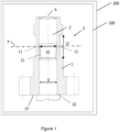
- the attached figure represents as an example an embodiment of a timepiece.
- FIG. 1 is a diagram of an embodiment of a timepiece.
- the timepiece is for example a watch or a wristwatch.
- the timepiece may comprise a watch movement 100, in particular a mechanical watch movement, in particular automatic, or electronic.
- the timepiece may also comprise a watch assembly, in particular a watch case intended to contain the movement.
- the movement comprises an assembly 3 or a friction system 3 comprising a shaft 2 and a tube 1.
- the shaft is housed in the tube 1.
- the tube 1 is a cannon or a cannon shaft and the shaft 2 is a center pinion, in particular a shafted center pinion.
- the shaft 2 and the tube 1 each have diameters D that are equal to the ready functional clearance that allow the tube 1 to slide freely relative to the shaft 2 along an axis A and that allow the tube to rotate freely relative to the shaft 2 about the axis A.
- the diameters D are for example between 0.3 mm and 2 mm, or even between 0.6 mm and 1 mm. Preferably, the diameters D are less than or equal to 2 mm, or even less than or equal to 1 mm.
- the assembly comprises a lantern, that is to say that the shaft 2 and/or the tube further comprise particular conformations 11, 21 in order to create friction between the tube and the shaft 2.
- the shaft 2 includes a groove or tapered clearance 21.
- the tube comprises at least one hump 11 or at least one hump, preferably two, three or four humps made in the same plane P perpendicular to the axis A or at least substantially in the same plane P perpendicular to the axis A.
- the hump(s) are made in a portion 12 of lesser thickness of the roadway.
- the groove or the conical clearance on the one hand, and the bump(s) on the other hand are arranged to cooperate by contact with each other when the shaft 2 is positioned in the tube 1, in particular when the tube is driven into the shaft 2 until a shoulder 22 made on the shaft 2 comes into contact against a stop surface 13 of the tube.
- the bump(s) are in contact with a portion or circle of the groove or clearance having a diameter d1.
- the distance d2 (not shown) between bosses or the diameter d2 of the circle inscribed in the right cross-section of the tube at the tops of the bosses or in the vicinity of the tops of the bosses is less than the diameter d1.
- the tube 1 is elastically deformed at the bumps, such that the distance between the bumps or the diameter of the circle inscribed in the right cross-section of the tube at the tops of the bumps or in the vicinity of the tops of the bumps is d1. It follows that the tube 1 exerts radial or substantially radial forces on the shaft 2. Combined with the shaft-tube friction, these forces define a shaft-tube friction torque. The torque depends mainly on the stiffness of the bumps and/or the elastic deformation of the bumps and/or the coefficient of friction at the shaft-tube interface.
- the friction torque between the shaft 2 and the tube 1 is greater than or equal to 1.8 mNm, or even greater than or equal to 2.0 mNm.
- the tube 1 may be a tube of a cannon.
- a needle may be fixed on such a tube.
- a needle may be kinematically connected to such a tube.
- the assembly may be used for correcting one or more hands indicating time information.
- the assembly may be used to correct any type of organ indicating time information or information derived from the time, in particular to correct a disk.
- the assembly may be a clutch or a torque limiter.
- the shaft 2 may be axially movable relative to the tube 1 between a position such as that shown in the figure 1 (engaged position) and a position in which the bumps are opposite a deeper groove in the shaft 2 in which they do not rub (disengaged position in which the tube 1 rotates freely around the shaft).
- tube 1 is made of 20AP alloy or Finemac alloy.
- tube 1 may be made of stainless steel.
- tube 1 may be made of a beryllium copper alloy such as CuBe2.
- shaft 2 is made of 20AP alloy or Finemac alloy.
- the method for producing the tube 1 comprises a step of plastic deformation of the tube 1, in particular a step of plastic deformation of the tube 1 controlled in deformation, the deformation step being carried out on a portion of the tube in the annealed state and/or whose elastic limit is less than 1000 MPa and/or whose hardness is less than 400 HV or less than 350 HV.
- the applied heat treatment has almost no influence on the dimensions of the part, while it induces a modification of the part's response to mechanical stresses.
- the response to torque is thus more homogeneous on parts pinched in the annealed state or in the delivery state than on parts previously hardened and then pinched.
- the implementation of dimensionally controlled pinching improves the dimensional regularity of the interbumps.
- the dispersion induced by the pinching of the uncured material is less than on the cured material.
- the pinching exhibits a more homogeneous and repeatable behavior than on the thermally cured material, and the dispersion of the final dimensions of the tube 1, in particular of the interbump dimension d2, linked to the process, is significantly lower.
- plastic deformation step is for example carried out on the material as delivered, slightly work hardened or in the annealed state. It makes it possible to obtain plastic deformations of greater amplitude, which then makes it possible to obtain greater friction torques, for example beyond 1.6 mNm. Associated with the control of the pinch in dimension and no longer in force, this solution also makes it possible to reduce dispersion within the road lots and to avoid the pairing of tubes 1 and shafts 2.
- the step of plastic deformation of the tube 1 comprises the production of at least one bump in the tube. This deformation is preferably carried out by pinching.
- the tube hardening step may include a quenching treatment followed by stress-relieving annealing and, if necessary, a tempering treatment, or a structural hardening annealing treatment.
- a higher friction torque of the tube-shaft assembly can be obtained.
- the manufacturing range of the tubes is modified, and the bumps are made on the tubes before the hardening heat treatment.
- the higher the friction torque the more the risks of the minute hand slipping relative to the center pinion are avoided, in the event of an impact in particular. If the hand is heavy (made of precious metals) or large, the risk of slipping in the event of an impact is high, for a given friction torque.
- the plastic deformation of the tube 1 to form the bumps is carried out not by controlling the force of a clamp pressing on the tube, but by controlling and/or measuring the displacement of the material at inside the tube 1.
- the distance between the bumps can be measured and/or controlled when making or forming them.
- the tube pinching is performed on the hardened material (e.g. Rp0.2[20AP] > 1800 MPa and Rp0.2[Finemac] > 1600 MPa after hardening heat treatment).
- the hardened material e.g. Rp0.2[20AP] > 1800 MPa and Rp0.2[Finemac] > 1600 MPa after hardening heat treatment.
- the deformation step is for example carried out by pinching the tube 1.
- the deformation step is for example carried out on a portion 12 of the tube whose elongation at break is greater than or equal to 2%, or even greater than or equal to 5%.
- the deformation step can be controlled by optical measurement of the deformation.
- the deformation step can be controlled by a template arranged in the tube during the deformation step or by passing gauges. In such a case, during the action of the clamp, the tube is deformed until the bumps formed in the tube come into contact with the template.
- the template is chosen with a diameter smaller than the diameter d2, so that after the elastic shrinkage of the material at the end of the deformation action, the distance between the bumps or the diameter of the circle inscribed in the right cross-section of the tube at the peaks of the bumps or in the vicinity of the peaks of the bumps is d2.
- An embodiment of a tube according to the invention is obtained by implementing the method described above.
- All tubes 1 of a batch delivered in the annealed state can be deformed in a repeatable manner.
- this heat treatment applied after plastic deformation has a weak influence on the dimensions of tube 1, and the tolerances are thereby tightened. It is therefore possible to obtain, according to the methods described, a set of at least 500 tubes whose standard deviation of the diameters of the circles centered on the axes A and inscribed in the cross-sections of the tubes at the peaks of the bumps is less than 0.2 ⁇ m for a nominal value of 0.758 mm.
- An embodiment of a method for producing friction between the shaft 2 and the tube 1 comprises a phase of implementing the method for producing a tube 1 described previously and a step of placing the shaft 2 in the tube 1.
- the change in range compared to the prior art has revealed a surprising behavior of the material in that the response to pinching is more homogeneous on a work-hardened material than on a hardened material and in that the hardening heat treatment does not influence the dimensions of the part.
- the change in range thus makes it possible to increase the deformation of the tube and to generate, for equal initial dimensions, larger and more homogeneous bumps which will induce a higher final torque. This therefore makes it possible to ensure a sufficiently high torque between the tube and the shaft, capable of subsequently supporting heavier needles.
- the rework rate is significantly lower.
Landscapes
- Physics & Mathematics (AREA)
- General Physics & Mathematics (AREA)
- Shafts, Cranks, Connecting Bars, And Related Bearings (AREA)
- Engineering & Computer Science (AREA)
- Manufacturing & Machinery (AREA)
- Metallurgy (AREA)
- Gears, Cams (AREA)
- Forging (AREA)
- Micromachines (AREA)
- Automatic Assembly (AREA)
- Mutual Connection Of Rods And Tubes (AREA)
Priority Applications (1)
| Application Number | Priority Date | Filing Date | Title |
|---|---|---|---|
| EP24199963.0A EP4455797A3 (de) | 2018-09-03 | 2018-09-03 | Verfahren zur herstellung einer reibe durch entreiben |
Applications Claiming Priority (2)
| Application Number | Priority Date | Filing Date | Title |
|---|---|---|---|
| EP18192226.1A EP3617811B1 (de) | 2018-09-03 | 2018-09-03 | Herstellungsverfahren einer reibung mittels rutschkupplung |
| EP24199963.0A EP4455797A3 (de) | 2018-09-03 | 2018-09-03 | Verfahren zur herstellung einer reibe durch entreiben |
Related Parent Applications (1)
| Application Number | Title | Priority Date | Filing Date |
|---|---|---|---|
| EP18192226.1A Division EP3617811B1 (de) | 2018-09-03 | 2018-09-03 | Herstellungsverfahren einer reibung mittels rutschkupplung |
Publications (2)
| Publication Number | Publication Date |
|---|---|
| EP4455797A2 true EP4455797A2 (de) | 2024-10-30 |
| EP4455797A3 EP4455797A3 (de) | 2024-12-25 |
Family
ID=63490314
Family Applications (2)
| Application Number | Title | Priority Date | Filing Date |
|---|---|---|---|
| EP24199963.0A Pending EP4455797A3 (de) | 2018-09-03 | 2018-09-03 | Verfahren zur herstellung einer reibe durch entreiben |
| EP18192226.1A Active EP3617811B1 (de) | 2018-09-03 | 2018-09-03 | Herstellungsverfahren einer reibung mittels rutschkupplung |
Family Applications After (1)
| Application Number | Title | Priority Date | Filing Date |
|---|---|---|---|
| EP18192226.1A Active EP3617811B1 (de) | 2018-09-03 | 2018-09-03 | Herstellungsverfahren einer reibung mittels rutschkupplung |
Country Status (4)
| Country | Link |
|---|---|
| US (2) | US11256216B2 (de) |
| EP (2) | EP4455797A3 (de) |
| JP (2) | JP2020064050A (de) |
| CN (1) | CN110874048B (de) |
Families Citing this family (2)
| Publication number | Priority date | Publication date | Assignee | Title |
|---|---|---|---|---|
| EP4455797A3 (de) * | 2018-09-03 | 2024-12-25 | Rolex Sa | Verfahren zur herstellung einer reibe durch entreiben |
| EP3742236B1 (de) * | 2019-05-23 | 2025-04-09 | Rolex Sa | Uhrvorrichtung, die eine erste komponente umfasst, die auf einer zweiten komponente durch plastische verformung fixiert ist |
Citations (3)
| Publication number | Priority date | Publication date | Assignee | Title |
|---|---|---|---|---|
| CH41140A (fr) | 1907-10-12 | 1908-09-16 | Langendorf Horlogerie | Arbre de grande moyenne, avec chaussée |
| CH129931A (fr) | 1927-11-19 | 1928-11-15 | Tavannes Watch Co Sa | Minuterie pour mouvement d'horlogerie. |
| EP2881803A1 (de) | 2013-12-09 | 2015-06-10 | Montres Breguet SA | Minutenrohr einer Uhr |
Family Cites Families (21)
| Publication number | Priority date | Publication date | Assignee | Title |
|---|---|---|---|---|
| CH104836A (fr) * | 1923-06-16 | 1924-05-16 | Schaad & Gilomen | Dispositif d'ajustement à frottement gras d'une chaussée de minuterie sur son axe. |
| CH1022571A4 (de) * | 1971-07-12 | 1973-05-30 | ||
| US3930361A (en) * | 1973-10-16 | 1976-01-06 | Citizen Watch Co., Ltd. | Slip wheel structure of a watch movement |
| JPS5066671U (de) * | 1973-10-16 | 1975-06-14 | ||
| JPS57105493A (en) * | 1980-12-23 | 1982-06-30 | Seiko Epson Corp | Analogically displaying wristwatch |
| JPS59106089U (ja) * | 1983-01-06 | 1984-07-17 | シチズン時計株式会社 | 腕時計の2番車構造 |
| CH685462B5 (fr) * | 1993-12-13 | 1996-01-31 | Patek Philippe Sa | Dispositif d'accouplement a friction pour mouvement d'horlogerie. |
| US6194088B1 (en) * | 1997-11-12 | 2001-02-27 | Daido Steel Co., Ltd. | Stainless steel coated with intermetallic compound and process for producing the same |
| GB0017684D0 (en) * | 2000-07-19 | 2000-09-06 | Bae Systems Plc | Tool positioning system |
| JP2002266078A (ja) * | 2001-03-12 | 2002-09-18 | Seiko Epson Corp | 摺動部品、スリップ機構および時計 |
| JP3757872B2 (ja) * | 2002-01-23 | 2006-03-22 | セイコーエプソン株式会社 | 動力伝達用歯車、およびこれを備えた機器 |
| CH708818A2 (fr) * | 2013-11-06 | 2015-05-15 | Eta Sa Manufacture Horlogère Suisse | Mobile d'horlogerie à roue unidirectionnelle. |
| EP2881804B1 (de) * | 2013-12-09 | 2017-08-02 | Montres Breguet S.A. | Spiralfeder-spiralklötzchen-einheit für uhrwerk |
| US10245631B2 (en) * | 2014-10-13 | 2019-04-02 | Victaulic Company | Roller set and pipe elements |
| WO2016183390A1 (en) * | 2015-05-13 | 2016-11-17 | Taktia Llc | Systems, methods and apparatus for guided tools |
| CH711571B1 (fr) * | 2015-09-28 | 2019-10-31 | Nivarox Sa | Oscillateur à détente tournante. |
| CN105525240B (zh) * | 2015-12-11 | 2018-02-13 | 北京奥普科星技术有限公司 | 一种提高6063铝合金强度与塑性的轧制热处理工艺 |
| EP3208664B1 (de) * | 2016-02-19 | 2023-08-16 | Omega SA | Uhrwerk oder uhr ohne magnetische signatur |
| CN105861968B (zh) * | 2016-03-30 | 2018-01-16 | 中南大学 | 一种提高Al‑Cu系高强铝合金环件力学性能的方法 |
| EP3285123B1 (de) * | 2016-08-15 | 2021-04-14 | Rolex Sa | Vorrichtung zum aufziehen eines uhrwerks |
| EP4455797A3 (de) * | 2018-09-03 | 2024-12-25 | Rolex Sa | Verfahren zur herstellung einer reibe durch entreiben |
-
2018
- 2018-09-03 EP EP24199963.0A patent/EP4455797A3/de active Pending
- 2018-09-03 EP EP18192226.1A patent/EP3617811B1/de active Active
-
2019
- 2019-08-27 US US16/552,141 patent/US11256216B2/en active Active
- 2019-08-27 JP JP2019154294A patent/JP2020064050A/ja active Pending
- 2019-09-03 CN CN201910829301.8A patent/CN110874048B/zh active Active
-
2022
- 2022-01-31 US US17/589,290 patent/US11507021B2/en active Active
-
2025
- 2025-02-07 JP JP2025018956A patent/JP2025076469A/ja active Pending
Patent Citations (3)
| Publication number | Priority date | Publication date | Assignee | Title |
|---|---|---|---|---|
| CH41140A (fr) | 1907-10-12 | 1908-09-16 | Langendorf Horlogerie | Arbre de grande moyenne, avec chaussée |
| CH129931A (fr) | 1927-11-19 | 1928-11-15 | Tavannes Watch Co Sa | Minuterie pour mouvement d'horlogerie. |
| EP2881803A1 (de) | 2013-12-09 | 2015-06-10 | Montres Breguet SA | Minutenrohr einer Uhr |
Also Published As
| Publication number | Publication date |
|---|---|
| US11507021B2 (en) | 2022-11-22 |
| EP3617811B1 (de) | 2024-10-02 |
| CN110874048A (zh) | 2020-03-10 |
| US20200073328A1 (en) | 2020-03-05 |
| CN110874048B (zh) | 2023-11-24 |
| JP2020064050A (ja) | 2020-04-23 |
| EP3617811A1 (de) | 2020-03-04 |
| EP4455797A3 (de) | 2024-12-25 |
| JP2025076469A (ja) | 2025-05-15 |
| US20220155726A1 (en) | 2022-05-19 |
| US11256216B2 (en) | 2022-02-22 |
Similar Documents
| Publication | Publication Date | Title |
|---|---|---|
| EP0886195B1 (de) | Selbstkompensierende Spiralfeder für mechanische Uhrwerkunruhspiralfederoszillator und Verfahren zu deren Herstellung | |
| EP3181940B2 (de) | Herstellungsverfahren einer spiralfeder mit einer vorbestimmten steifigkeit durch lokalisierte wegnahme von material | |
| EP2930572B1 (de) | Uhrensortiment, das eine amorphe metalllegierung verwendet | |
| EP3617811B1 (de) | Herstellungsverfahren einer reibung mittels rutschkupplung | |
| EP3584640A1 (de) | Oszillator für uhr | |
| EP3743538B1 (de) | Gelenkzapfen eines regulators und verfahren zu dessen herstellung | |
| EP2881803B1 (de) | Minutenrohr einer Uhr | |
| EP2585880A1 (de) | Uhrziffernblattfüsse | |
| EP2813906A1 (de) | Bauteil für Uhrwerk | |
| CH716669A1 (fr) | Procédé de fabrication d'un arbre de pivotement de balancier. | |
| CH705420B1 (fr) | Assemblage de pièce en matériau fragile. | |
| EP3379342A1 (de) | Vorrichtung, die eine schnelleinstellfeder für uhrwerke umfasst, die mit einer triebfeder zusammenwirkt | |
| CH712719A2 (fr) | Composant horloger pour mouvement d'horlogerie. | |
| EP3273305B1 (de) | Bauteil für uhrwerk | |
| EP3273304B1 (de) | Bauteil für uhrwerk | |
| EP3882710A1 (de) | Verfahren zur herstellung einer uhrenkomponente auf siliziumbasis | |
| EP3112955B1 (de) | Herstellungsverfahren eines werkstücks, das einen modifizierten polierschritt umfasst | |
| EP3800511B1 (de) | Schwenkachse eines regulierorgans | |
| EP4327165A1 (de) | Verfahren zur herstellung eines uhrendrehbolzens und durch dieses verfahren erhaltener uhrendrehstift | |
| EP3223085B1 (de) | Vorrichtung, die eine schnelleinstellfeder für uhrwerke umfasst | |
| CH718550A2 (fr) | Axe de pivotement horloger et procédé de fabrication d'un tel axe de pivotement horloger. | |
| CH721306A2 (fr) | Procédé de fabrication d'un oscillateur balancier-spiral pour spiraux à forte variation de couple | |
| EP3037463A1 (de) | Verbundmaterial, insbesondere für uhrmacherei | |
| CH711923B1 (fr) | Procédé de fabrication d'une pièce composite avec moyens élastiques sous contrainte, pièce composite et assortiment horloger. | |
| CH718549A2 (fr) | Composant horloger et procédé de fabrication d'un tel composant horloger. |
Legal Events
| Date | Code | Title | Description |
|---|---|---|---|
| PUAI | Public reference made under article 153(3) epc to a published international application that has entered the european phase |
Free format text: ORIGINAL CODE: 0009012 |
|
| STAA | Information on the status of an ep patent application or granted ep patent |
Free format text: STATUS: THE APPLICATION HAS BEEN PUBLISHED |
|
| AC | Divisional application: reference to earlier application |
Ref document number: 3617811 Country of ref document: EP Kind code of ref document: P |
|
| AK | Designated contracting states |
Kind code of ref document: A2 Designated state(s): AL AT BE BG CH CY CZ DE DK EE ES FI FR GB GR HR HU IE IS IT LI LT LU LV MC MK MT NL NO PL PT RO RS SE SI SK SM TR |
|
| PUAL | Search report despatched |
Free format text: ORIGINAL CODE: 0009013 |
|
| AK | Designated contracting states |
Kind code of ref document: A3 Designated state(s): AL AT BE BG CH CY CZ DE DK EE ES FI FR GB GR HR HU IE IS IT LI LT LU LV MC MK MT NL NO PL PT RO RS SE SI SK SM TR |
|
| RIC1 | Information provided on ipc code assigned before grant |
Ipc: G04B 13/02 20060101AFI20241118BHEP |
|
| P01 | Opt-out of the competence of the unified patent court (upc) registered |
Free format text: CASE NUMBER: APP_63682/2024 Effective date: 20241130 |
|
| STAA | Information on the status of an ep patent application or granted ep patent |
Free format text: STATUS: REQUEST FOR EXAMINATION WAS MADE |
|
| 17P | Request for examination filed |
Effective date: 20250625 |