EP4454916A1 - Elektrisches arbeitsfahrzeug - Google Patents
Elektrisches arbeitsfahrzeug Download PDFInfo
- Publication number
- EP4454916A1 EP4454916A1 EP22910655.4A EP22910655A EP4454916A1 EP 4454916 A1 EP4454916 A1 EP 4454916A1 EP 22910655 A EP22910655 A EP 22910655A EP 4454916 A1 EP4454916 A1 EP 4454916A1
- Authority
- EP
- European Patent Office
- Prior art keywords
- case lid
- case
- work vehicle
- case body
- peripheral wall
- Prior art date
- Legal status (The legal status is an assumption and is not a legal conclusion. Google has not performed a legal analysis and makes no representation as to the accuracy of the status listed.)
- Pending
Links
Images






Classifications
-
- H—ELECTRICITY
- H02—GENERATION; CONVERSION OR DISTRIBUTION OF ELECTRIC POWER
- H02K—DYNAMO-ELECTRIC MACHINES
- H02K11/00—Structural association of dynamo-electric machines with electric components or with devices for shielding, monitoring or protection
- H02K11/30—Structural association with control circuits or drive circuits
- H02K11/33—Drive circuits, e.g. power electronics
-
- A—HUMAN NECESSITIES
- A01—AGRICULTURE; FORESTRY; ANIMAL HUSBANDRY; HUNTING; TRAPPING; FISHING
- A01D—HARVESTING; MOWING
- A01D34/00—Mowers; Mowing apparatus of harvesters
- A01D34/01—Mowers; Mowing apparatus of harvesters characterised by features relating to the type of cutting apparatus
- A01D34/412—Mowers; Mowing apparatus of harvesters characterised by features relating to the type of cutting apparatus having rotating cutters
- A01D34/63—Mowers; Mowing apparatus of harvesters characterised by features relating to the type of cutting apparatus having rotating cutters having cutters rotating about a vertical axis
- A01D34/81—Casings; Housings
-
- B—PERFORMING OPERATIONS; TRANSPORTING
- B60—VEHICLES IN GENERAL
- B60K—ARRANGEMENT OR MOUNTING OF PROPULSION UNITS OR OF TRANSMISSIONS IN VEHICLES; ARRANGEMENT OR MOUNTING OF PLURAL DIVERSE PRIME-MOVERS IN VEHICLES; AUXILIARY DRIVES FOR VEHICLES; INSTRUMENTATION OR DASHBOARDS FOR VEHICLES; ARRANGEMENTS IN CONNECTION WITH COOLING, AIR INTAKE, GAS EXHAUST OR FUEL SUPPLY OF PROPULSION UNITS IN VEHICLES
- B60K1/00—Arrangement or mounting of electrical propulsion units
- B60K1/04—Arrangement or mounting of electrical propulsion units of the electric storage means for propulsion
-
- B—PERFORMING OPERATIONS; TRANSPORTING
- B60—VEHICLES IN GENERAL
- B60L—PROPULSION OF ELECTRICALLY-PROPELLED VEHICLES; SUPPLYING ELECTRIC POWER FOR AUXILIARY EQUIPMENT OF ELECTRICALLY-PROPELLED VEHICLES; ELECTRODYNAMIC BRAKE SYSTEMS FOR VEHICLES IN GENERAL; MAGNETIC SUSPENSION OR LEVITATION FOR VEHICLES; MONITORING OPERATING VARIABLES OF ELECTRICALLY-PROPELLED VEHICLES; ELECTRIC SAFETY DEVICES FOR ELECTRICALLY-PROPELLED VEHICLES
- B60L15/00—Methods, circuits, or devices for controlling the traction-motor speed of electrically-propelled vehicles
- B60L15/007—Physical arrangements or structures of drive train converters specially adapted for the propulsion motors of electric vehicles
-
- B—PERFORMING OPERATIONS; TRANSPORTING
- B60—VEHICLES IN GENERAL
- B60L—PROPULSION OF ELECTRICALLY-PROPELLED VEHICLES; SUPPLYING ELECTRIC POWER FOR AUXILIARY EQUIPMENT OF ELECTRICALLY-PROPELLED VEHICLES; ELECTRODYNAMIC BRAKE SYSTEMS FOR VEHICLES IN GENERAL; MAGNETIC SUSPENSION OR LEVITATION FOR VEHICLES; MONITORING OPERATING VARIABLES OF ELECTRICALLY-PROPELLED VEHICLES; ELECTRIC SAFETY DEVICES FOR ELECTRICALLY-PROPELLED VEHICLES
- B60L50/00—Electric propulsion with power supplied within the vehicle
- B60L50/50—Electric propulsion with power supplied within the vehicle using propulsion power supplied by batteries or fuel cells
- B60L50/60—Electric propulsion with power supplied within the vehicle using propulsion power supplied by batteries or fuel cells using power supplied by batteries
-
- H—ELECTRICITY
- H02—GENERATION; CONVERSION OR DISTRIBUTION OF ELECTRIC POWER
- H02G—INSTALLATION OF ELECTRIC CABLES OR LINES, OR OF COMBINED OPTICAL AND ELECTRIC CABLES OR LINES
- H02G3/00—Installations of electric cables or lines or protective tubing therefor in or on buildings, equivalent structures or vehicles
- H02G3/02—Details
- H02G3/08—Distribution boxes; Connection or junction boxes
- H02G3/14—Fastening of cover or lid to box
-
- H—ELECTRICITY
- H02—GENERATION; CONVERSION OR DISTRIBUTION OF ELECTRIC POWER
- H02G—INSTALLATION OF ELECTRIC CABLES OR LINES, OR OF COMBINED OPTICAL AND ELECTRIC CABLES OR LINES
- H02G3/00—Installations of electric cables or lines or protective tubing therefor in or on buildings, equivalent structures or vehicles
- H02G3/02—Details
- H02G3/08—Distribution boxes; Connection or junction boxes
- H02G3/16—Distribution boxes; Connection or junction boxes structurally associated with support for line-connecting terminals within the box
-
- H—ELECTRICITY
- H05—ELECTRIC TECHNIQUES NOT OTHERWISE PROVIDED FOR
- H05K—PRINTED CIRCUITS; CASINGS OR CONSTRUCTIONAL DETAILS OF ELECTRIC APPARATUS; MANUFACTURE OF ASSEMBLAGES OF ELECTRICAL COMPONENTS
- H05K7/00—Constructional details common to different types of electric apparatus
- H05K7/14—Mounting supporting structure in casing or on frame or rack
- H05K7/1422—Printed circuit boards receptacles, e.g. stacked structures, electronic circuit modules or box like frames
- H05K7/1427—Housings
- H05K7/1432—Housings specially adapted for power drive units or power converters
-
- A—HUMAN NECESSITIES
- A01—AGRICULTURE; FORESTRY; ANIMAL HUSBANDRY; HUNTING; TRAPPING; FISHING
- A01D—HARVESTING; MOWING
- A01D2101/00—Lawn-mowers
-
- A—HUMAN NECESSITIES
- A01—AGRICULTURE; FORESTRY; ANIMAL HUSBANDRY; HUNTING; TRAPPING; FISHING
- A01D—HARVESTING; MOWING
- A01D69/00—Driving mechanisms or parts thereof for harvesters or mowers
- A01D69/02—Driving mechanisms or parts thereof for harvesters or mowers electric
-
- B—PERFORMING OPERATIONS; TRANSPORTING
- B60—VEHICLES IN GENERAL
- B60L—PROPULSION OF ELECTRICALLY-PROPELLED VEHICLES; SUPPLYING ELECTRIC POWER FOR AUXILIARY EQUIPMENT OF ELECTRICALLY-PROPELLED VEHICLES; ELECTRODYNAMIC BRAKE SYSTEMS FOR VEHICLES IN GENERAL; MAGNETIC SUSPENSION OR LEVITATION FOR VEHICLES; MONITORING OPERATING VARIABLES OF ELECTRICALLY-PROPELLED VEHICLES; ELECTRIC SAFETY DEVICES FOR ELECTRICALLY-PROPELLED VEHICLES
- B60L2200/00—Type of vehicles
- B60L2200/40—Working vehicles
-
- B—PERFORMING OPERATIONS; TRANSPORTING
- B60—VEHICLES IN GENERAL
- B60L—PROPULSION OF ELECTRICALLY-PROPELLED VEHICLES; SUPPLYING ELECTRIC POWER FOR AUXILIARY EQUIPMENT OF ELECTRICALLY-PROPELLED VEHICLES; ELECTRODYNAMIC BRAKE SYSTEMS FOR VEHICLES IN GENERAL; MAGNETIC SUSPENSION OR LEVITATION FOR VEHICLES; MONITORING OPERATING VARIABLES OF ELECTRICALLY-PROPELLED VEHICLES; ELECTRIC SAFETY DEVICES FOR ELECTRICALLY-PROPELLED VEHICLES
- B60L2270/00—Problem solutions or means not otherwise provided for
- B60L2270/10—Emission reduction
- B60L2270/14—Emission reduction of noise
- B60L2270/145—Structure borne vibrations
Definitions
- the present invention relates to an electric work vehicle that includes a battery, a motor driven by electric power supplied from the battery, and a travel device driven by the motor.
- Patent Document 1 An electric work vehicle such as described above has already been disclosed in Patent Document 1, for example.
- This electric work vehicle (“tractor” in Patent Document 1) has an inverter device (“inverter” in Patent Document 1) interposed on the power supply path from the battery to the electric motor.
- Patent Document 1 JP 2021-953A
- the electric work vehicle having the structure shown in Patent Document 1 has a reasonably sturdily support structure in which a large inverter support portion that is supported by left and right body frames is integrally formed with a relatively sturdily battery support base for supporting a large battery. Attaching the inverter device to the inverter support portion serving a sturdy support structure allows transmission of shaking, vibration and the like to the inverter device to be suppressed as much as possible.
- the invention aims to reduce the effects of shaking, vibration and the like transmitted to an inverter device by providing the inverter device itself with a vibration resistance function.
- Patent Document 1 merely shows the inverter device as a box-shaped body, and the specific structure thereof is not disclosed.
- the inverter device When the inverter device has a structure that merely combines a box-shaped body and a lid body, with an inverter circuit housed in the box-shaped body being accessed for maintenance purposes by opening the lid body, the region of the case body where the case lid opens and closes is required to be firmly sealed, so as to reliably avoid ingress of dust, rainwater, and the like from outside through this region. Furthermore, measures are also needed to avoid degradation of the sealing properties due to deterioration of the seal over time, and there is room for improvement in terms of the risk of adding complexity to the structure and making the opening/closing operation more troublesome.
- the invention further aims to provide an electric work vehicle in which ingress of dust, rainwater, and the like through the region where an exterior case used as an inverter device opens and closes is readily reliably avoided with a simple structure.
- the rigidity of the exterior case housing the substrate provided with the inverter circuit is enhanced by forming a reinforcing rib on the outer surface of the peripheral wall portion of the case body and on the inner surface of the case lid. A reduction in shaking, vibration and the like transmitted to the inverter device can thereby be achieved.
- the reinforcing rib formed on the exterior case is advantageous in terms of being able to enhance the heat dissipation effect obtained through contact with the outside air, as a result of being formed of the outer surface of the peripheral wall portion of the case body.
- the reinforcing rib formed on the inner surface of the case lid helps strengthen the exterior case as a whole, while accumulation of dust is readily avoided and installation of the exterior case in the narrow space between the vehicle body frame and the battery installation base is facilitated, as a result of a reinforcing rib that protrudes upward not being provided on the upper surface of the case lid.
- the at least one reinforcing rib formed on the peripheral wall portion is at least one vertical rib extending in an up-down direction
- the at least one reinforcing rib formed on the inner surface of the case lid is at least one diagonal grid-shaped rib extending in a diagonal direction of the case lid.
- the at least one vertical rib does not protrude outside an outer peripheral edge of an upper end of the peripheral wall portion, and the peripheral wall portion includes an outer wall surface between the vertical ribs positioned adjacent to each other that is formed as a recessed wall surface recessed to approach closer to an inner wall surface of the case body than is a place where the vertical ribs are formed.
- the high vertical strength of the exterior case is maintained as a result of the vertical ribs, while securing a large surface area of the peripheral wall portion as a result of the outer wall surface located between the vertical ribs being formed as a recessed wall surface that is recessed to approach the inner wall surface of the case body. Heat is thereby readily efficiently dissipated, and weight reduction is readily achieved at the same time.
- the at least one vertical rib overlaps, in side view, with a screw hole formed in the peripheral wall portion in order to fasten the case lid to the case body.
- the at least one diagonal grid-shaped rib extends in a direction joining coupling holes for bolt insertion formed in a rectangular peripheral portion of the case lid.
- the diagonal grid-shaped rib on the case lid extending in a direction that joins coupling holes for bolt insertion, the diagonal grid-shaped rib acts like a brace while the case body and the case lid are fastened together, and the strength of the exterior case as a whole is readily enhanced.
- the inner surface of the case lid includes a region in which part of the at least one diagonal grid-shaped rib protruding into the space does not exist, and between the case lid and a component attached to the case body at a place facing the region is formed a space for securing an insulation distance.
- the exterior case is constituted by a conductive member
- the provision of a region in which part of the diagonal grid-shaped rib protruding into the inner space of the case does not exist enables a space for securing an insulation distance to be formed between that region and a component facing that region.
- the bottom plate portion is provided, on a lower surface thereof, with a grid-shaped rib extending in the front-back direction and the left-right direction parallel to extension directions of the peripheral wall portion in plan view.
- a cushioning material for vibration isolation preferably between an upper end surface of the peripheral wall portion of the case body and an inner surface of a peripheral portion of the case lid is sandwiched a cushioning material for vibration isolation.
- the substrate stopping portion fixedly supports, on an upper surface of the bottom plate portion, a peripheral portion and a vicinity of a central portion of the substrate provided with the inverter circuit.
- the substrate itself is less likely to flex, and shaking, vibration and the like are more readily suppressed.
- the substrate stopping portion includes a plurality of protruding pedestals for receiving and fastening the substrate, and the protruding pedestals positioned adjacent to each other are connected by a coupling rib.
- the protruding pedestals of the substrate stopping portion are connected to each other by a coupling rib, and shaking, vibration and the like of the protruding pedestals are readily suppressed.
- an electric work vehicle of the invention is characterized by including:
- a lip portion located on the outer side of the upper end portion of the case body and lower than the upper end portion of the case body is formed on a lower peripheral portion of the case lid configured to open and close the open upper end of the case body. Accordingly, the open upper end of the case body can be closed, with the outer side of the contact point between the case body and the case lid surrounded by the lip portion, compared to a structure in which the case body and the case lid are merely coupled together by coupling bolts.
- the upper end of the case body and the case lid contact each other at a point higher than the lower peripheral portion of the case lid, and the contact point has a gasket interposed therein.
- a gasket is provided at the contact point between the upper end of the case body and the case lid, at a higher position than the lower peripheral portion of the case lid, which portion is located on the outer side the upper end portion of the case body, and thus the possibility of this gasket coming into direct contact with dust, rainwater, and the like from outside is reduced. Ingress of dust, rainwater, and the like inside of the exterior case is thereby more readily prevented.
- the case lid is provided, on part of an outer peripheral portion thereof, with a striking protrusion protruding outward.
- a striking protrusion that partially protrudes outward is formed on an outer peripheral portion of the case lid, and thus, if the case lid is difficult to open due to sticking to the upper end of the case body as a result of not been opened and closed for an extended period of time, this situation is readily resolved by striking the striking protrusion from outside.
- the striking protrusion protrudes horizontally outward from between bolt holes formed on a periphery of the outer peripheral portion of the case lid.
- the striking protrusion protrudes horizontally outward from between the bolt holes formed on the periphery of the outer peripheral portion of the case lid, and thus the force generated by the striking action works effectively on the place where the degree of adhesion is high due to being firmly tightened by the coupling bolts, and the situation where the case lid is adhered to the case body is more readily resolved.
- the striking protrusion is provided with a reinforcing rib extending in a protruding direction of the striking protrusion.
- the striking protrusion can be reinforced with a reinforcing rib, and the force generated by the striking action is readily accurately applied to the adhesion point between the case lid and the case body.
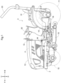
- the tractor includes left and right front wheels 10, left and right rear wheels 11, and a cover member 12.
- the tractor includes a body frame 2 and a driving section 3.
- the body frame 2 is supported by the left and right front wheels 10 and the left and right rear wheels 11.
- the cover member 12 is disposed in a front body portion.
- the driving section 3 is provided behind the cover member 12. In other words, the cover member 12 is disposed in front of the driving section 3.
- the driving section 3 has a protective frame 30, a driver's seat 31, and a steering wheel 32. An operator can sit in the driver's seat 31. The operator can thereby ride in the driving section 3. The left and right front wheels 10 are steered by operating the steering wheel 32. The operator is able to perform various driving operations in the driving section 3.
- the tractor is provided with a travel battery 4. Also, the cover member 12 is pivotable about an opening-closing axis Q extending the left-right direction of the body. The cover member 12 is thereby openable and closable. While the cover member 12 is closed, the travel battery 4 is covered by the cover member 12.
- the tractor includes an inverter 14 (corresponds to inverter device) and a motor M.
- the travel battery 4 supplies electric power to the inverter 14.
- the inverter 14 converts DC power from the travel battery 4 into AC power and supplies the AC power to the motor M.
- the motor M is then driven by the AC power supplied from the inverter 14.
- the tractor includes a hydrostatic continuously variable transmission (CVT) 15 and a transmission 16.
- CVT continuously variable transmission
- the hydrostatic CVT 15 has a hydraulic pump 15a and a hydraulic motor 15b.
- the hydraulic pump 15a is driven by rotational power from the motor M. Rotational power is output from the hydraulic motor 15b, in response to the hydraulic pump 15a being driven. Note that, in the hydrostatic CVT 15, rotational power is varied between the hydraulic pump 15a and the hydraulic motor 15b. Also, the transmission ratio of the hydrostatic CVT 15 can be changed continuously.
- the rotational power output from the hydraulic motor 15b is transmitted to the transmission 16.
- the rotational power transmitted to the transmission 16 is varied by a geared transmission mechanism of the transmission 16 and distributed to the left and right front wheels 10 and the left and right rear wheels 11.
- the left and right front wheels 10 and the left and right rear wheels 11 are thereby driven.
- the tractor includes a mid power takeoff (PTO) shaft 17 and a rear power takeoff (PTO) shaft 18.
- the rotational power output from the motor M is distributed to the hydraulic pump 15a, the mid PTO shaft 17, and the rear PTO shaft 18.
- the mid PTO shaft 17 and the rear PTO shaft 18 thereby rotate.
- a work device is connected to the mid PTO shaft 17 (or the rear PTO shaft 18), the work device will be driven by the rotational power of the mid PTO shaft 17 (or the rear PTO shaft 18).
- a mowing device 19 is connected to the mid PTO shaft 17. The mowing device 19 is driven by the rotational power of the mid PTO shaft 17.
- the body frame 2 includes left and right front-back frames 2A and a lateral frame 2B.
- the left and right front-back frames 2A extend in the front-back direction of the body, and the lateral frame 2B joins the left and right front-back frames 2A to each other.
- the lateral frame 2B is coupled to lower portions of the left and right front-back frames 2A, and extends in the front-back direction in a plan view from the region where the front end portion of the inverter 14 is located to the region where the front end portion of the motor M is located.
- the lateral frame 2B is coupled to an axle unit 10F extending in the left-right direction of the body of the tractor (corresponds to electric work vehicle).
- the front wheels 10 are rotationally supported by left and right end portions of the axle unit 10F.
- the transmission 16 and the axle unit 10F are coupled to a propeller shaft 13 extending in the front-back direction of the body below the lateral frame 2B.
- the inverter 14 and the motor M are disposed adjacent to each other in the front-back direction. In other words, the inverter 14 and the motor M are aligned with each other in the front-back direction of the body.
- the motor M and the inverter 14 are supported by the left and right front-back frames 2A in such a manner as to be aligned with each other in the front-back direction of the body between the left and right front-back frames 2A.
- the inverter 14 is in front of the motor M.
- the inverter 14 and the motor M are connected by a power supply cable 21.
- the power supply cable 21 is detachably connected at one end portion 21A to an output connector 14C of the inverter 14, and is detachably connected at an opposite end 21B to a power receiving connector 22 of the motor M.
- the output connector 14C is located in a region of the exterior case 5 on the opposite side to the motor M.
- the power supply cable 21 is located above the lateral frame 2B and is housed between the left and right front-back frames 2A. That is, the power supply cable 21 extends in the front-back direction through the space surrounded by the left and right front-back frames 2A, the lateral frame 2B, and a bottom plate portion 50 of the exterior case 5. The possibility of the output connector 14C and the power supply cable 21 coming into contact with foreign objects is thereby avoided, and the possibility of the output connector 14C and the power supply cable 21 becoming detached in response to coming into contact with foreign objects can be reduced.
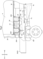
- the travel battery 4 is supported by the left and right front-back frames 2A in such a manner as to be located directly above the inverter 14. Specifically, as shown in FIGS. 4 to 6 , on upper end portions of the left and right front-back frames 2A are respectively formed left and right support surface portions 23. On the left and right support surface portions 23 is placed a battery installation base 24, and the travel battery 4 is placed on the battery installation base 24.
- the left and right support surface portions 23 extend in the lateral direction of the body at upper end portions of the left and right front-back frames 2A.
- triangular ribs 27 extend between the support surface portions 23 and the front-back frames 2A to prevent the left and right support surface portions 23 from sagging with respect to the left and right front-back frames 2A.
- the triangular ribs 27 are welded, at contact sides thereof, to the front-back frames 2A and the support surface portions 23, and the support surface portions 23 are thereby integrally formed with the front-back frames 2A via the triangular ribs 27, and constitute part of the body frame 2.
- the bottom portion of the inverter 14 is coupled to the support surface portions 23 by attachment bolts 28. The inverter 14 is thus removably supported by the body frame 2.
- the battery installation base 24 is bolted to the left and right support surface portions 23. As shown in FIGS. 4 to 6 , the battery installation base 24 is formed by welding together attachment plates 24C that respectively partially overlap with the left and right support surface portions 23, C-shaped steel vertical frames 24A that extends in the up-down direction on the attachment plates 24C, left and right steel angles 24B that extend in the front-back direction of the body at upper end portions of the left and right vertical frames 24A, and a lateral steel angle that joins the left and right steel angles 24B extending in the front-back direction of the body.
- the attachment plates 24C have bolt insertion holes 24Ca for bolting the attachment plates 24C to the support surface portions 23 formed therein, and the attachment plates 24C and the support surface portions 23 can be fixedly coupled together via coupling bolts 26.
- the battery installation base 24 is gate shaped as viewed in the front-back direction of the body. The battery installation base 24 covers the inverter 14 from above and from the left and right sides.
- the inverter 14 of the present embodiment will now be described with reference to FIGS. 4 to 15 .
- the inverter 14 converts direct current from the travel battery 4 into alternating current and supplies the alternating current to the motor M.
- the inverter 14 houses a substrate 60 on which an inverter circuit 6 is provided, a capacitor 61, and the like in the exterior case 5 which includes a case body 5A and a case lid 5B.
- the inverter circuit 6 is a circuit body that converts direct current from the travel battery 4 into alternating current, and is provided with an inverter module constituted by an insulated gate bipolar transistor (IGBT), for example, and by an inverter control module that communicates with a higher-order electronic control unit (ECU) and controls the inverter module.
- the capacitor 61 holds the supply voltage for the inverter module at a constant voltage.
- the substrate 60 includes a first substrate 60A on which the inverter module is provided and a second substrate 60B on which the inverter control module is provided.
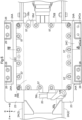
- a first substrate stopping portion 51 for fixing the first substrate 60A As shown in FIGS. 12 and 13 , on the bottom plate portion 50 of the case body 5A is provided a first substrate stopping portion 51 for fixing the first substrate 60A.
- a second substrate stopping portion 52 is provided for fixing the second substrate 60B, which is a different substrate 60 from the first substrate 60A, at a position overlapping the first substrate 60A from above.
- the first substrate stopping portion 51 includes protruding pedestals 53 for receiving a peripheral portion and a central portion of the first substrate 60A and fixing the peripheral and central portions of the first substrate 60A to the bottom plate portion 50.
- the peripheral and central portions of the first substrate 60A are fixed to the bottom plate portion 50, using screw holes provided in the protruding pedestals 53 and set screws, with the protruding pedestals 53 positioned to face the peripheral and central portions of the first substrate 60A.
- the second substrate stopping portion 52 includes an attachment plate 62 capable of supporting a peripheral portion and a central portion of the second substrate 60B, and protruding pedestals 53 for receiving a peripheral portion of the attachment plate 62 and fixing the peripheral portion of the attachment plate 62 to the bottom plate portion 50.
- the peripheral and central portions of the second substrate 60B supported by the attachment plate 62 are fixed to the bottom plate portion 50, as a result of the attachment plate 62 being fixed to the bottom plate portion 50, using screw holes provided in the protruding pedestals 53 and set screws, with the protruding pedestals 53 positioned to face the peripheral portion of the attachment plate 62, while the peripheral and central portions of the second substrate 60B are supported by the attachment plate 62.
- some of the adjacently positioned protruding pedestals 53 are connected to each other by coupling ribs 54.
- the protruding pedestals 53 having a high protruding height upward from the bottom plate portion 50 and are for fixing the attachment plate 62 to the bottom plate portion 50 are connected to each other and to the inner surface of the case body 5A described later by the coupling ribs 54. Shaking of the protruding pedestals 53 having a high protruding height from the bottom plate portion 50 is thereby readily effectively suppressed. As a result, transmission of shaking, vibration and the like to the attachment plate 62 and the second substrate 60B fixed to the attachment plate 62 are readily reduced.
- the travel battery 4 and the inverter 14 are electrically connected to each other by a power cable 20 (corresponds to input harness). Direct current flows through the power cable 20.
- the inverter 14 is provided with an input connector 14B (corresponds to input connection portion).
- the input connector 14B protrudes forward of a front portion of the exterior case 5 and is electrically connected to a connection port 20A of the power cable 20.
- the inverter 14 includes the input connector 14B electrically connected to the power cable 20, the inverter circuit 6 that converts direct current into alternating current, and the output connector 14C (output connection portion) electrically connected to the power supply cable 21 (corresponds to the output harness).
- the exterior case 5 is an aluminum die-cast product that includes the case body 5A having a rectangular box shape and the case lid 5B having a rectangular plate shape.
- the rectangular box-shaped case body 5A includes the bottom plate portion 50 and a peripheral wall portion 55, and the space surrounded by the bottom plate portion 50 and the peripheral wall portion 55 is open upward.
- the case lid 5B is couplable to and uncouplable from an upper end portion of the case body 5A, in such a manner that the opening in the case body 5A is openable and closable.
- the first substrate stopping portion 51 and the second substrate stopping portion 52 for fixing the substrate 60 are provided on the bottom plate portion 50 of the case body 5A.
- the inverter circuit 6 is housed in the exterior case 5 by closing the opening of the case body 5A with the case lid 5B, with the first substrate 60A and the second substrate 60B respectively attached to the first substrate stopping portion 51 and the second substrate stopping portion 52.
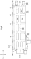
- grid-shaped reinforcing ribs 56 including vertical ribs 55a that extend in the up-down direction and lateral ribs 55b that extend in the horizontal direction.
- the reinforcing ribs 56 are formed in such a manner that the vertical ribs 55a and the lateral ribs 55b do not protrude outside the outer peripheral edge of the upper end of the peripheral wall portion 55.
- the outer wall surface between the adjacent vertical ribs 55a is formed as a recessed wall surface provided, at various places, with recessed portions 55c that are recessed to approach closer to the inner wall surface of the case body 5A than are places where the vertical ribs 55a are formed.
- the vertical ribs 55a and the lateral ribs 55b are not formed to protrude outward of the outer peripheral edge of the upper end of the peripheral wall portion 55, but, conversely, are the portions that remain as reinforcing ribs 56, as a result of the peripheral wall portion 55 being formed in such a manner that part of the outer wall surface thereof is recessed by providing the recessed portions 55c.
- screw holes 55d into which coupling bolts 57 for fastening the case lid 5B while the case lid 5B faces the opening in the case body 5A are screwable.
- the screw holes 55d are formed at positions that overlap with the vertical ribs 55a in side view.
- the recess depth of the recessed portions 55c corresponds to a distance d1 from the outer end to the inner end of the vertical ribs 55a.
- the far inner portion of the recessed portions 55c is formed to approach closer to the inner wall surface of the peripheral wall portion 55 than are the places where the coupling bolts 57 are provided.
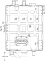
- the grid-shaped reinforcing ribs 56 are formed not only on the left side surface shown in FIG. 8 and the rear surface shown in FIG. 9 , but are also similarly formed on the front surface shown in FIG. 5 and on the right side surface which is not shown.
- reinforcing ribs 56 including front-rear ribs 50a extending in the front-back direction and left-right ribs 50b extending in the left-right direction.
- attachment seats 50d for fixing the case body 5A to the support surface portions 23 of the front-back frames 2A.
- These attachment seats 50d are provided with attachment holes 50e for fixing via the attachment bolt 28.
- the front-rear ribs 50a and the left-right ribs 50b are also formed by providing upward-facing recessed portions 50c in the place surrounded by the front-rear ribs 50a and the left-right ribs 50b, rather than being formed to protrude lower than the lower surface of the attachment seat 50d provided at the lower end of the outer peripheral edge of the bottom plate portion 50.
- the recess depth of the upward-facing recessed portion 50c corresponds to a distance d2 from the lower end to the upper end of the front-rear ribs 50a and the left-right ribs 50b.
- the recessed portions 50c are formed to be shallower than the recessed portions 55c, by making this distance d2 shorter than the distance d1 (see FIG. 13 ) corresponding to the recess depth of the recessed portions 55c in the peripheral wall portion 55 described above.
- the peripheral wall portion 55 of the case body 5A includes a rear-facing wall portion 55R that faces the rearward side of the body and is provided with a breathing hole 7 for ventilation through which air inside the exterior case 5 can be exhausted.
- This breathing hole 7 is provided with a filter 70 to allow internal air to be exhausted following a rise in air pressure within the exterior case 5 due to factors such as heat generated by the inverter circuit 6, and to restrict ingress of dust, rainwater, and the like from outside.
- the exterior case 5 is installed on the front-back frames 2A so as to be allocated on the left and right of a vertical line CL that passes through a central position between the left and right front-back frames 2A in the left-right direction, that is, a central position in the left-right direction of the body.
- the vertical line CL intersects an axis (not shown) of the axle unit 10F of the front wheels 10 that extends in the front-back direction as viewed in the front-back direction of the body. Accordingly, the exterior case 5 is installed on the front-back frames 2A in the vicinity of the place where shake of the front-back frames 2A in the left-right direction when the front wheels 10 are rolling about the axis extending in the front-back direction is minimal.
- the travel battery 4 is located above the exterior case 5, and the exterior case 5 is covered by the travel battery 4 and the battery installation base 24 for installing the travel battery 4.
- the lateral frame 2B that joins the left and right front-back frames 2A and the support surface portions 23 provided on the upper edge of the front-back frames 2A are located below the exterior case 5.
- the lower side of the exterior case 5 is thereby blocked by the left-right lateral frame 2B and the support surface portions 23.
- the breathing hole 7 provided in the rear-facing wall portion 55R is located between the left and right front-back frames 2A in the left-right direction. Furthermore, as shown in FIG. 9 , the breathing hole 7 is located between the vertical line CL and the front-back frame 2A on the right side.
- the case lid 5B couplable to and uncouplable from the upper end portion of the case body 5A is constituted as follows.
- the case lid 5B has a large number of bolt insertion holes 58a (correspond to coupling holes) formed in a peripheral portion of the rectangular plate-shaped lid plate 58.
- the coupling bolts 57 are inserted into these bolt insertion holes 58a and a large number of screw holes 55d formed at the upper end portion of the peripheral wall portion 55 of the case body 5A, and the case lid 5B can be fastened with the case lid 5B facing the opening of the case body 5A.
- a rib-shaped lip portion 58b that protrudes downward along the outer edge of the lid plate 58 is formed on the outer peripheral end portion of the lid plate 58.
- the lengths of the inner peripheral surface of the lip portion 58b in the front-back direction and the left-right direction are slightly larger than the lengths of the outer peripheral surface of the upper end portion of the peripheral wall portion 55 in the front-back direction and the left-right direction, such that the lip portion 58b externally fits to the upper end portion of the peripheral wall portion 55.
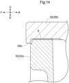
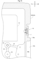
- the lip portion 58b fits together with the upper end of the peripheral wall portion 55 to partially overlap in the up-down direction. While the case lid 5B is thus externally fitted to the peripheral wall portion 55 of the case body 5A, the contact point between the upper end of the peripheral wall portion 55 of the case body 5A and the lower surface of the case lid 5B at a position facing the upper end thereof is higher than the lower end of the lip portion 58b corresponding to the lower peripheral portion of the case lid 5B.
- the case lid 5B is fixed in such a manner as to be externally fitted to the upper end portion of the peripheral wall portion 55 of the case body 5A.
- a resin gasket 8 interposed between the upper end of the peripheral wall portion 55 of the case body 5A and the outer peripheral end portion on the inner side of the lip portion 58b of the lid plate 58 is a resin gasket 8 as a sealing material that doubles as a cushioning material.
- the contact point between the upper end of the peripheral wall portion 55 of the case body 5A and the lower surface of the case lid 5B at a position facing the upper end of the peripheral wall portion 55 is higher than the lower end of the lip portion 58b corresponding to the lower peripheral portion of the case lid 5B, and thus the position of the gasket 8 interposed in that region is also higher than the lower end of the lip portion 58b corresponding to the lower peripheral portion of the case lid 5B.
- the gasket 8 is also effective in suppressing propagation of vibration from the case body 5A to the case lid 5B, and, conversely, propagation of vibration from the case lid 5B to the case body 5A.
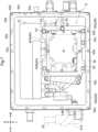
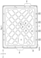
- the upper surface of the lid plate 58 that forms the case lid 5B is almost completely flat except for the periphery of the bolt insertion holes 58a, whiles on the lower surface of the lid plate 58 is formed a surface on which a large number of reinforcing ribs 56 are formed, as shown in FIG. 11 .
- the reinforcing ribs 56 are diagonal grid-shaped ribs 59a and 59b of the lid plate 58 that extend diagonally.
- the portion surrounded by the diagonal grid-shaped ribs 59a and 59b is an upward-facing recessed portion 59c that is recessed toward the upper surface of the case lid 5B.
- the lower surface of the lid plate 58 located between the diagonal grid-shaped ribs 59a and 59b is not formed to protrude lower than the lower end of the lip portion 58b, but, conversely, is formed as recessed wall surface provided, at various places, with the recessed portions 59c that are recessed to approach the upper surface of the lid plate 58.
- the diagonal grid-shaped ribs 59a and 59b are thus the portions that remain as reinforcing ribs 56, as a result of part of the lower surface of the lid plate 58 being recessed by providing the recessed portions 59c.
- the recess depth of the upward-facing recessed portion 59c corresponds to a distance d3 from the lower end to the upper end of the diagonal grid-shaped ribs 59a and 59b.
- the recessed portions 50c are formed to be shallower than the recessed portions 55c, by making this distance d3 shorter than the distance d1 (see FIG. 13 ) corresponding to the recess depth of the recessed portions 55c in the peripheral wall portion 55 described above.
- the diagonal grid-shaped ribs 59a and 59b are formed to extend in directions joining the bolt insertion holes 58a formed in the rectangular peripheral portion of the case lid 5B.
- part of the lower surface of the case lid 5B (inner surface of exterior case 5) has a region S 1 in which the diagonal grid-shaped ribs 59a and 59b protruding toward the inner space of the exterior case 5 are not provided.
- the diagonal grid-shaped ribs 59a and 59b extending in directions joining the bolt insertion holes 58a are formed in such a manner as to be interrupted partway between one bolt insertion hole 58a and another bolt insertion hole 58a.
- the far inner surface (lower surface of case lid 5B) of the region S 1 will be closer to the upper surface of the case lid 5B by the protruding height of the diagonal grid-shaped ribs 59a and 59b, and about the same position as the recess depth of the recessed portion 59c.
- This region S1 is provided to form an insulation distance securing space for allowing a distance for insulating purposes to be secured between the case lid 5B and components attached to the case body 5A at places facing the region S1.
- the case lid 5B is integrally molded with striking protrusions 58c that protrude outward from part of the outer peripheral portion of the lid plate 58.
- the striking protrusions 58c protrude horizontally outward from between the bolt insertion holes 58a (corresponds to bolt holes) formed on the periphery of the outer peripheral portion of the lid plate 58.
- the striking protrusions 58c also have ribs 58d (correspond to reinforcing ribs 56) that extend in the protruding direction of the striking protrusions 58c formed thereon (see FIGS. 6 and 9 ).
- case lid 5B When the case lid 5B is firmly coupled to the case body 5A by tightening down the coupling bolts 57 and is not opened or closed for an extended period of time, the case lid 5B may be difficult to open even when the coupling bolts 57 are removed, due to becoming stuck to the upper end of the case body 5A.
- the place where the case lid 5B and the upper end of the peripheral wall portion 55 fit together may be constituted as follows. That is, it is desirable that, between the inner peripheral surface of the lip portion 58b formed on the outer peripheral portion of the case lid 5B and the outer peripheral surface of the upper end portion of the peripheral wall portion 55, the inner peripheral surface of the lip portion 58b is set to a size that can be separated from the outer peripheral surface of the upper end portion of the peripheral wall portion 55, such that there at least is a slight horizontal gap, as shown in FIGS. 12 to 14 .
- the remaining configuration can be similar to the above-described embodiment.
- two substrates 60 are housed in the exterior case 5 as the inverter circuit 6, but the number of substrates 60 is not limited to two, and may be only one or may be three or more.
- the remaining configuration can be similar to the above-described embodiment.
- the exterior case 5 is constituted by a rectangular box-shaped case body 5A and a rectangular plate-shaped case lid 5B, but the exterior case 5 is not limited to being rectangular, and may be other shapes.
- the remaining configuration can be similar to the above-described embodiment.
- the grid-shaped reinforcing ribs 56 are formed on the entirety of the peripheral wall portion 55 and the bottom plate portion 50 of the case body 5A, but are not limited to this structure, and the reinforcing ribs 56 may be formed on only part of the peripheral wall portion 55 and the bottom plate portion 50 of the case body 5A.
- the remaining configuration can be similar to the above-described embodiment.
- the grid-shaped reinforcing ribs 56 are similarly formed on the entirety of the peripheral wall portion 55 and the bottom plate portion 50 of the case body 5A, but are not necessarily limited to this structure, and the reinforcing ribs 56 may be formed in an appropriate combination, such as the vertical rib 55a being formed on the left and right peripheral wall portions 55, the lateral rib 55b being formed on the front and rear peripheral wall portions 55, and the front-rear rib 50a being formed on the lower surface of the bottom plate portion 50.
- extension direction of the reinforcing ribs 56 is not limited to up/down, horizontal, front/back and left/right, and may be set as appropriate, such as diagonally or in any direction.
- the remaining configuration can be similar to the above-described embodiment.
- the reinforcing ribs 56 are materialized by forming the recessed portions 55c in the recess direction from a wall surface serving as a reference such as the outer peripheral edge of the upper end of the peripheral wall portion 55, but are not necessarily limited to this structure.
- reinforcing ribs 56 that protrude laterally outward from a reference wall surface such as the outer peripheral edge of the upper end of the peripheral wall portion 55 may be provided.
- the wall surface of the exterior case 5 may include a portion on which the reinforcing ribs 56 are not provided.
- the remaining configuration can be similar to the above-described embodiment.
- the diagonal grid-shaped ribs 59a and 59b extending in diagonal directions of the lid plate 58 are provided as reinforcing ribs 56 formed on the lower surface of the lid plate 58, but the reinforcing ribs 56 are not necessarily limited to this structure.
- grid-shaped reinforcing ribs 56 in which the front-back direction and the left-right direction intersect along the periphery of the lid plate 58 instead of the diagonal directions may be provided.
- diagonal reinforcing ribs 56 that extend along diagonal directions of the lid plate 58, longitudinal reinforcing ribs 56 that extend along the periphery of the lid plate 58, or lateral reinforcing ribs 56 that extend along the periphery of the lid plate 58 may be provided.
- the remaining configuration can be similar to the above-described embodiment.
- the reinforcing ribs 56 are formed only on the lower surface of the lid plate 58, but are not necessarily limited to this structure. Reinforcing ribs 56 having an appropriate structure can be employed, such as reinforcing ribs 56 formed only on the upper surface of the lid plate 58, or reinforcing ribs 56 formed on both the lower and upper surfaces of the lid plate 58.
- the remaining configuration can be similar to the above-described embodiment.
- the plurality of protruding pedestals 53 used as substrate stopping portions include protruding pedestals 53 having a high protruding height upward that are joined together by coupling ribs 54, but this structure need not necessarily be employed, and, for example, protruding pedestals 53 having a low protruding height may be coupled together, or low and high protruding pedestals 53 may be joined together.
- the remaining configuration can be similar to the above-described embodiment.
- the lip portion 58b protrudes downward from the periphery of the lid plate 58 by a constant amount, but is not necessarily limited to this structure, and the lip portion may protrude downward longer or shorter in places on the periphery of the lid plate 58.
- the amount of downward protrusion may be lengthened in places that are predicted to often be exposed to dust or rainwater from outside, such as increasing the amount of downward protrusion on the front side of the body, for example.
- the remaining configuration can be similar to the above-described embodiment.
- the lip portion 58b protrudes downward from the entire periphery of the lid plate 58, but is not necessarily limited to this structure, and there may be places on the periphery of the lid plate 58 where the lip portion 58b is not provided.
- the remaining configuration can be similar to the above-described embodiment.
- the invention can be utilized not only for tractors but also for various electric work vehicles such as combine harvesters, rice transplanters, and construction work machines.
Landscapes
- Engineering & Computer Science (AREA)
- Power Engineering (AREA)
- Transportation (AREA)
- Mechanical Engineering (AREA)
- Microelectronics & Electronic Packaging (AREA)
- Life Sciences & Earth Sciences (AREA)
- Sustainable Development (AREA)
- Sustainable Energy (AREA)
- Architecture (AREA)
- Civil Engineering (AREA)
- Structural Engineering (AREA)
- Environmental Sciences (AREA)
- Chemical & Material Sciences (AREA)
- Combustion & Propulsion (AREA)
- Arrangement Or Mounting Of Propulsion Units For Vehicles (AREA)
Applications Claiming Priority (3)
| Application Number | Priority Date | Filing Date | Title |
|---|---|---|---|
| JP2021211636A JP7550744B2 (ja) | 2021-12-24 | 2021-12-24 | 電動作業車 |
| JP2021211637A JP7565908B2 (ja) | 2021-12-24 | 2021-12-24 | 電動作業車 |
| PCT/JP2022/042000 WO2023119936A1 (ja) | 2021-12-24 | 2022-11-10 | 電動作業車 |
Publications (2)
| Publication Number | Publication Date |
|---|---|
| EP4454916A1 true EP4454916A1 (de) | 2024-10-30 |
| EP4454916A4 EP4454916A4 (de) | 2026-04-01 |
Family
ID=86902087
Family Applications (1)
| Application Number | Title | Priority Date | Filing Date |
|---|---|---|---|
| EP22910655.4A Pending EP4454916A4 (de) | 2021-12-24 | 2022-11-10 | Elektrisches arbeitsfahrzeug |
Country Status (3)
| Country | Link |
|---|---|
| US (1) | US20240305172A1 (de) |
| EP (1) | EP4454916A4 (de) |
| WO (1) | WO2023119936A1 (de) |
Family Cites Families (23)
| Publication number | Priority date | Publication date | Assignee | Title |
|---|---|---|---|---|
| JPH0727238U (ja) * | 1993-10-25 | 1995-05-19 | 矢崎総業株式会社 | 電気接続箱 |
| JPH11122875A (ja) * | 1997-10-13 | 1999-04-30 | Toshiba Corp | 電動機 |
| JP3866065B2 (ja) * | 2001-08-23 | 2007-01-10 | 株式会社ケンウッド | 筐体シールド防水構造 |
| WO2013175651A1 (ja) * | 2012-05-22 | 2013-11-28 | 旭化成ケミカルズ株式会社 | 板状部分の強度を向上する構造及び略直方体形状の部材 |
| US10011324B2 (en) * | 2012-12-25 | 2018-07-03 | Kawasaki Jukogyo Kabushiki Kaisha | Electric vehicle |
| WO2014102853A1 (ja) * | 2012-12-25 | 2014-07-03 | 川崎重工業株式会社 | 電動車両 |
| CN203504423U (zh) * | 2013-07-30 | 2014-03-26 | 深圳市晶福源电子技术有限公司 | 一种逆变器的限位和加强性结构和逆变器 |
| CN204290754U (zh) * | 2014-12-30 | 2015-04-22 | 深圳市汇川技术股份有限公司 | 光伏逆变器箱体 |
| US10225927B2 (en) * | 2015-12-02 | 2019-03-05 | Nsk Ltd. | Structure of substrate having electronic parts mounted thereon and case for housing the substrate |
| US12068496B2 (en) * | 2018-07-30 | 2024-08-20 | Sanyo Electric Co., Ltd. | Battery system including exterior case fixed to vehicle via external fixing brackets and vehicle equipped with battery system |
| KR102171845B1 (ko) * | 2019-06-03 | 2020-10-29 | 뉴모텍(주) | 인버터 하우징이 탑재된 전기 자동차의 구동모터 |
| JP7224245B2 (ja) * | 2019-06-24 | 2023-02-17 | 株式会社クボタ | 電動作業車 |
| JP7264778B2 (ja) * | 2019-09-09 | 2023-04-25 | 株式会社クボタ | 筐体および電動草刈機 |
| JP7279888B2 (ja) * | 2019-09-27 | 2023-05-23 | 住友電工デバイス・イノベーション株式会社 | 光半導体装置及び光半導体装置の製造方法 |
| US20250135957A1 (en) * | 2023-10-30 | 2025-05-01 | Kubota Corporation | Electric work vehicle |
| US20250140983A1 (en) * | 2023-10-30 | 2025-05-01 | Kubota Corporation | Electric work vehicle |
| US20250140974A1 (en) * | 2023-10-30 | 2025-05-01 | Kubota Corporation | Electric work vehicle |
| US20250135956A1 (en) * | 2023-10-30 | 2025-05-01 | Kubota Corporation | Electric work vehicle |
| US20250135919A1 (en) * | 2023-10-30 | 2025-05-01 | Kubota Corporation | Electric work vehicle |
| US12358448B2 (en) * | 2023-10-30 | 2025-07-15 | Kubota Corporation | Electric work vehicle |
| US12570162B2 (en) * | 2023-10-30 | 2026-03-10 | Kubota Corporation | Electric work vehicle |
| US20250141013A1 (en) * | 2023-10-30 | 2025-05-01 | Kubota Corporation | Electric work vehicle |
| US12594829B2 (en) * | 2023-10-30 | 2026-04-07 | Kubota Corporation | Electric work vehicle |
-
2022
- 2022-11-10 EP EP22910655.4A patent/EP4454916A4/de active Pending
- 2022-11-10 WO PCT/JP2022/042000 patent/WO2023119936A1/ja not_active Ceased
-
2024
- 2024-05-17 US US18/667,280 patent/US20240305172A1/en active Pending
Also Published As
| Publication number | Publication date |
|---|---|
| EP4454916A4 (de) | 2026-04-01 |
| US20240305172A1 (en) | 2024-09-12 |
| WO2023119936A1 (ja) | 2023-06-29 |
Similar Documents
| Publication | Publication Date | Title |
|---|---|---|
| US11034226B2 (en) | Vehicle | |
| JP7020804B2 (ja) | バッテリパック | |
| US11691492B2 (en) | Assembly for securing a vehicle battery on a body of a motor vehicle, and method for mounting a vehicle battery in a motor vehicle | |
| US8877364B2 (en) | Battery pack | |
| US7380866B2 (en) | Door construction for vehicle | |
| JPH06199137A (ja) | 電気自動車 | |
| JP2020050124A (ja) | 車体前部構造 | |
| CN111016823A (zh) | 接头及车辆 | |
| JP6830979B2 (ja) | 車両用バッテリユニットの冷却構造 | |
| JPH06199183A (ja) | 電気自動車のコンソールボックス | |
| EP4454916A1 (de) | Elektrisches arbeitsfahrzeug | |
| JP7675642B2 (ja) | 電動作業車 | |
| WO2024142480A1 (ja) | 電動作業車 | |
| JP2003260939A (ja) | 燃料電池車両のフロア構造 | |
| JP7565908B2 (ja) | 電動作業車 | |
| JP7789124B2 (ja) | 電動作業車 | |
| JP7550744B2 (ja) | 電動作業車 | |
| WO2024142481A1 (ja) | 電動作業車 | |
| JP6163450B2 (ja) | 電気デバイスの冷却構造 | |
| JP2015202697A (ja) | 電気デバイス収容体 | |
| JP2015214233A (ja) | 電気デバイスの搭載構造 | |
| JP7617837B2 (ja) | 電動作業車 | |
| JP2021030962A (ja) | 電動車両 | |
| JP2021011262A (ja) | 車両 | |
| JP3284849B2 (ja) | 電気自動車のバッテリ格納部構造 |
Legal Events
| Date | Code | Title | Description |
|---|---|---|---|
| STAA | Information on the status of an ep patent application or granted ep patent |
Free format text: STATUS: THE INTERNATIONAL PUBLICATION HAS BEEN MADE |
|
| PUAI | Public reference made under article 153(3) epc to a published international application that has entered the european phase |
Free format text: ORIGINAL CODE: 0009012 |
|
| STAA | Information on the status of an ep patent application or granted ep patent |
Free format text: STATUS: REQUEST FOR EXAMINATION WAS MADE |
|
| 17P | Request for examination filed |
Effective date: 20240523 |
|
| AK | Designated contracting states |
Kind code of ref document: A1 Designated state(s): AL AT BE BG CH CY CZ DE DK EE ES FI FR GB GR HR HU IE IS IT LI LT LU LV MC ME MK MT NL NO PL PT RO RS SE SI SK SM TR |
|
| DAV | Request for validation of the european patent (deleted) | ||
| DAX | Request for extension of the european patent (deleted) | ||
| RIC1 | Information provided on ipc code assigned before grant |
Ipc: B60K 1/04 20190101AFI20251201BHEP Ipc: H02G 3/14 20060101ALI20251201BHEP Ipc: H02G 3/16 20060101ALI20251201BHEP Ipc: H05K 5/00 20060101ALI20251201BHEP Ipc: H05K 5/02 20060101ALI20251201BHEP Ipc: H05K 5/03 20060101ALI20251201BHEP Ipc: A01D 34/81 20060101ALI20251201BHEP Ipc: B60L 15/00 20060101ALI20251201BHEP Ipc: B60L 50/60 20190101ALI20251201BHEP Ipc: H02K 11/33 20160101ALI20251201BHEP Ipc: A01D 69/02 20060101ALN20251201BHEP |
|
| A4 | Supplementary search report drawn up and despatched |
Effective date: 20260302 |
|
| RIC1 | Information provided on ipc code assigned before grant |
Ipc: B60K 1/04 20190101AFI20260224BHEP Ipc: H02G 3/14 20060101ALI20260224BHEP Ipc: H02G 3/16 20060101ALI20260224BHEP Ipc: H05K 5/00 20060101ALI20260224BHEP Ipc: H05K 5/02 20060101ALI20260224BHEP Ipc: H05K 5/03 20060101ALI20260224BHEP Ipc: A01D 34/81 20060101ALI20260224BHEP Ipc: B60L 15/00 20060101ALI20260224BHEP Ipc: B60L 50/60 20190101ALI20260224BHEP Ipc: H02K 11/33 20160101ALI20260224BHEP Ipc: A01D 69/02 20060101ALN20260224BHEP |