EP4454523A1 - Elektrischer kochherd - Google Patents
Elektrischer kochherd Download PDFInfo
- Publication number
- EP4454523A1 EP4454523A1 EP21904640.6A EP21904640A EP4454523A1 EP 4454523 A1 EP4454523 A1 EP 4454523A1 EP 21904640 A EP21904640 A EP 21904640A EP 4454523 A1 EP4454523 A1 EP 4454523A1
- Authority
- EP
- European Patent Office
- Prior art keywords
- width
- hinge shaft
- shaft
- operating lever
- lid member
- Prior art date
- Legal status (The legal status is an assumption and is not a legal conclusion. Google has not performed a legal analysis and makes no representation as to the accuracy of the status listed.)
- Pending
Links
Images


Classifications
-
- A—HUMAN NECESSITIES
- A47—FURNITURE; DOMESTIC ARTICLES OR APPLIANCES; COFFEE MILLS; SPICE MILLS; SUCTION CLEANERS IN GENERAL
- A47J—KITCHEN EQUIPMENT; COFFEE MILLS; SPICE MILLS; APPARATUS FOR MAKING BEVERAGES
- A47J37/00—Baking; Roasting; Grilling; Frying
- A47J37/06—Roasters; Grills; Sandwich grills
- A47J37/0611—Roasters; Grills; Sandwich grills the food being cooked between two heating plates, e.g. waffle-irons
-
- A—HUMAN NECESSITIES
- A47—FURNITURE; DOMESTIC ARTICLES OR APPLIANCES; COFFEE MILLS; SPICE MILLS; SUCTION CLEANERS IN GENERAL
- A47J—KITCHEN EQUIPMENT; COFFEE MILLS; SPICE MILLS; APPARATUS FOR MAKING BEVERAGES
- A47J37/00—Baking; Roasting; Grilling; Frying
- A47J37/01—Vessels uniquely adapted for baking
- A47J37/015—Vessels uniquely adapted for baking electrically heated
-
- E—FIXED CONSTRUCTIONS
- E05—LOCKS; KEYS; WINDOW OR DOOR FITTINGS; SAFES
- E05D—HINGES OR SUSPENSION DEVICES FOR DOORS, WINDOWS OR WINGS
- E05D5/00—Construction of single parts, e.g. the parts for attachment
- E05D5/10—Pins, sockets or sleeves; Removable pins
-
- E—FIXED CONSTRUCTIONS
- E05—LOCKS; KEYS; WINDOW OR DOOR FITTINGS; SAFES
- E05D—HINGES OR SUSPENSION DEVICES FOR DOORS, WINDOWS OR WINGS
- E05D7/00—Hinges or pivots of special construction
- E05D7/0009—Adjustable hinges
- E05D7/0018—Adjustable hinges at the hinge axis
- E05D7/0045—Adjustable hinges at the hinge axis in a radial direction
- E05D7/0054—Adjustable hinges at the hinge axis in a radial direction by means of eccentric parts
-
- E—FIXED CONSTRUCTIONS
- E05—LOCKS; KEYS; WINDOW OR DOOR FITTINGS; SAFES
- E05D—HINGES OR SUSPENSION DEVICES FOR DOORS, WINDOWS OR WINGS
- E05D7/00—Hinges or pivots of special construction
- E05D7/04—Hinges adjustable relative to the wing or the frame
-
- F—MECHANICAL ENGINEERING; LIGHTING; HEATING; WEAPONS; BLASTING
- F16—ENGINEERING ELEMENTS AND UNITS; GENERAL MEASURES FOR PRODUCING AND MAINTAINING EFFECTIVE FUNCTIONING OF MACHINES OR INSTALLATIONS; THERMAL INSULATION IN GENERAL
- F16C—SHAFTS; FLEXIBLE SHAFTS; ELEMENTS OR CRANKSHAFT MECHANISMS; ROTARY BODIES OTHER THAN GEARING ELEMENTS; BEARINGS
- F16C11/00—Pivots; Pivotal connections
- F16C11/04—Pivotal connections
-
- A—HUMAN NECESSITIES
- A47—FURNITURE; DOMESTIC ARTICLES OR APPLIANCES; COFFEE MILLS; SPICE MILLS; SUCTION CLEANERS IN GENERAL
- A47J—KITCHEN EQUIPMENT; COFFEE MILLS; SPICE MILLS; APPARATUS FOR MAKING BEVERAGES
- A47J37/00—Baking; Roasting; Grilling; Frying
- A47J37/06—Roasters; Grills; Sandwich grills
- A47J37/0611—Roasters; Grills; Sandwich grills the food being cooked between two heating plates, e.g. waffle-irons
- A47J2037/0617—Roasters; Grills; Sandwich grills the food being cooked between two heating plates, e.g. waffle-irons with means to adjust the distance between heating plates
-
- E—FIXED CONSTRUCTIONS
- E05—LOCKS; KEYS; WINDOW OR DOOR FITTINGS; SAFES
- E05D—HINGES OR SUSPENSION DEVICES FOR DOORS, WINDOWS OR WINGS
- E05D11/00—Additional features or accessories of hinges
- E05D11/06—Devices for limiting the opening movement of hinges
-
- E—FIXED CONSTRUCTIONS
- E05—LOCKS; KEYS; WINDOW OR DOOR FITTINGS; SAFES
- E05D—HINGES OR SUSPENSION DEVICES FOR DOORS, WINDOWS OR WINGS
- E05D5/00—Construction of single parts, e.g. the parts for attachment
- E05D5/10—Pins, sockets or sleeves; Removable pins
- E05D2005/102—Pins
- E05D2005/106—Pins with non-cylindrical portions
-
- E—FIXED CONSTRUCTIONS
- E05—LOCKS; KEYS; WINDOW OR DOOR FITTINGS; SAFES
- E05Y—INDEXING SCHEME ASSOCIATED WITH SUBCLASSES E05D AND E05F, RELATING TO CONSTRUCTION ELEMENTS, ELECTRIC CONTROL, POWER SUPPLY, POWER SIGNAL OR TRANSMISSION, USER INTERFACES, MOUNTING OR COUPLING, DETAILS, ACCESSORIES, AUXILIARY OPERATIONS NOT OTHERWISE PROVIDED FOR, APPLICATION THEREOF
- E05Y2201/00—Constructional elements; Accessories therefor
- E05Y2201/20—Brakes; Disengaging means; Holders; Stops; Valves; Accessories therefor
- E05Y2201/224—Stops
-
- E—FIXED CONSTRUCTIONS
- E05—LOCKS; KEYS; WINDOW OR DOOR FITTINGS; SAFES
- E05Y—INDEXING SCHEME ASSOCIATED WITH SUBCLASSES E05D AND E05F, RELATING TO CONSTRUCTION ELEMENTS, ELECTRIC CONTROL, POWER SUPPLY, POWER SIGNAL OR TRANSMISSION, USER INTERFACES, MOUNTING OR COUPLING, DETAILS, ACCESSORIES, AUXILIARY OPERATIONS NOT OTHERWISE PROVIDED FOR, APPLICATION THEREOF
- E05Y2800/00—Details, accessories and auxiliary operations not otherwise provided for
- E05Y2800/26—Form or shape
-
- E—FIXED CONSTRUCTIONS
- E05—LOCKS; KEYS; WINDOW OR DOOR FITTINGS; SAFES
- E05Y—INDEXING SCHEME ASSOCIATED WITH SUBCLASSES E05D AND E05F, RELATING TO CONSTRUCTION ELEMENTS, ELECTRIC CONTROL, POWER SUPPLY, POWER SIGNAL OR TRANSMISSION, USER INTERFACES, MOUNTING OR COUPLING, DETAILS, ACCESSORIES, AUXILIARY OPERATIONS NOT OTHERWISE PROVIDED FOR, APPLICATION THEREOF
- E05Y2800/00—Details, accessories and auxiliary operations not otherwise provided for
- E05Y2800/26—Form or shape
- E05Y2800/292—Form or shape having apertures
- E05Y2800/296—Slots
-
- E—FIXED CONSTRUCTIONS
- E05—LOCKS; KEYS; WINDOW OR DOOR FITTINGS; SAFES
- E05Y—INDEXING SCHEME ASSOCIATED WITH SUBCLASSES E05D AND E05F, RELATING TO CONSTRUCTION ELEMENTS, ELECTRIC CONTROL, POWER SUPPLY, POWER SIGNAL OR TRANSMISSION, USER INTERFACES, MOUNTING OR COUPLING, DETAILS, ACCESSORIES, AUXILIARY OPERATIONS NOT OTHERWISE PROVIDED FOR, APPLICATION THEREOF
- E05Y2900/00—Application of doors, windows, wings or fittings thereof
- E05Y2900/30—Application of doors, windows, wings or fittings thereof for domestic appliances
Definitions
- the present invention relates to an electric cooker for baking food such as bread, snack cake, and so on.
- an electric cooker has a base body to which a lower die plate is mounted on its upper surface and a lid member to which an upper die plate is mounted on its lower surface, and has a formation to bake a baking food that a rear portion of the lid member is pivotably supported to the base body by a hinge shaft, that dough is filled into a space formed between the upper and lower die plates, and that the upper and lower die plates are heated from each backside of them by electric heaters.
- Patent Literature 1 discloses an invention having a formation that upper and lower die plates are possible to be exchanged respectively according to a baking food to be capable of corresponding to plural kinds of baking foods, and that to avoid variation in a baking degree of the baking foods owing to the thickness of the upper and lower die plates, a hinge-shaft-height mechanism is provided on a rotation part of the lid member to the base body such that a hinge shaft which is a rotation center of the lid member is capable of adjusting its vertical position and facing surfaces of the respective lower and upper die plates are uniformly and closely fitted.
- Patent Literature 1 JP 5,662,624 B
- Patent Literature 1 While plural kinds of the upper and lower die plates different in each thickness are capable of being exchanged according to the kinds of the baking foods, and the hinge shaft is adjusted in a proper position by the hinge-shaft-height adjustment mechanism such that the facing surfaces of the respective lower and upper die plates can be uniformly and closely fitted, a manufacturing cost may increase because the hinge-shaft-height adjustment mechanism is complex in its structure.
- an object of the present invention is to provide a low-cost electric cooker having a hinge shaft capable of stepwise adjusting its vertical position according to the thickness of die plates used by a simple structure.
- the electric cooker of the present invention comprises:
- the engaging shaft portion of the hinge shaft is formed to have a long diameter direction larger than an open width of the narrow-width portion of the adjustment guide hole and a short diameter direction smaller than the open width of the narrow-width portion.
- the operating lever is capable of pivoting from a locked position in where the engaging shaft portion of the hinge shaft is incapable of passing through the narrow-width portion to a released position in where the engaging shaft portion of the hinge shaft is capable of passing through the narrow-width portion and vice versa.
- the operating lever has a first stopper abutting with the support portion to stop the operating lever in the locked position.
- the operating lever has a second stopper with which a part of the lid member abuts in a pivoting direction to stop the lid member in a fully open position when the operating lever is in the locked position.
- the hinge shaft is made to be capable of stepwise adjusting its vertical position according to the thickness of the die plates used by a simple structure, it is possible to provide a low-cost electric cooker to which plural kinds of die plates having different thickness can be respectively attached in a proper condition such that the plural kinds of die plates can be used in that single electric cooker.
- an electric cooker of the present invention has:
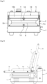
- a direction criteria of the lid member 5 and members attached to it is on the basis of a state that the lid member 5 is in a closed position to overlap the lower die plate 6 with the upper die plate 7 as shown in Fig. 1 and by a solid line in Fig. 2 .
- the electric cooker of the present embodiment has a basic shape of lateral symmetry except for certain parts, and thus a structure on the right side thereof is described as a representative example in the following description. Therefore, a direction in a structure on the left side of the electric cooker is opposite to the left-right direction explained concerning the structure on the right side thereof in the drawings.
- the electric cooker of the present embodiment is capable of stepwise adjusting the vertical position of the hinge shaft 4 supported by the adjustment guide holes 3 when the operating lever 8 composing a part of a hinge-shaft-height adjustment mechanism described later is operated to pivot such that the electric cooker is applicable for plural kinds of the lower and upper die plates 6, 7 respectively having different thickness.
- the hinge-shaft-height adjustment mechanism of the present invention has:
- a control box 9 is fixed to the rear end of the base body 1, wherein a power switch 9a, a heater temperature control knob 9b, and a pilot lamp 9c are arranged on an upper surface of the control box 9, and a control board (not shown) is housed in the control box 9.
- a base portion 2b elongated in the left-right direction of the support bracket 2 is fixed to the base body 1 in front of the control box 9 with a plurality of screws.
- the left and right support portions 2a of the support bracket 2 are respectively formed with the above-described adjustment guide holes 3 oriented in the vertical direction for guiding the engaging shaft portions 4a respectively formed on both end portions of the hinge shaft 4 to be rotatable and capable of vertically moving.
- the adjustment guide holes 3 is formed with a wide-width portion 3a and a narrow-width portion 3b alternately in the vertical direction.
- two wide-width portions 3a are formed in upper and lower positions and one narrow-width portion 3b is formed between the upper and lower wide-width portions 3a such that the hinge shaft 4 is capable of vertically adjusting its position in two steps.
- the present invention is not limited to this embodiment. It may be possible to vertically form more than three wide-width portions 3a such that the hinge shaft 4 is capable of vertically adjusting its position in more than three steps.
- the hinge shaft 4 is made of a solid cylindrical rod.
- the hinge shaft 4 is formed with the engaging shaft portions 4a on both end portions, the engaging shaft portions 4a being respectively engaged with the adjustment guide holes 3 to be capable of moving vertically and rotating. Particularly as shown in Fig. 9 , both sides of the engaging shaft portion 4a are cut such that a cross-section of the engaging shaft portions 4a is formed in an oval-like shape having a long diameter direction x and a short diameter direction y.
- a dimension a in the long diameter direction x of the engaging shaft portion 4a is set to rotatably engage with the wide-width portion 3a of the adjustment guide hole 3 and to be larger than an open width w of the narrow-width portion 3b.
- a dimension b in the short diameter direction y of the engaging shaft portions 4a is set to be smaller than the dimension a and to be smaller than the open width w of the narrow-width portion 3b.
- each of the engaging shaft portions 4a of the hinge shaft 4 when the each of engaging shaft portions 4a is in a position such that its long diameter direction y is oriented in the longitudinal direction, that is, in a locked position shown by a two-dot chain line in Fig. 9 and is engaged with the lower wide-width portion 3b of the adjustment guide hole 3, the hinge shaft 4 is rotatably held in the lower wide-width portion 3b.
- the operating lever 8 is made to be pivoted upward at an angle of about 90 degrees to a position shown by a solid line in Fig.
- the engaging shaft portion 4a is rotated to a released position where its long diameter direction x is oriented in the vertical direction and its short diameter direction y is oriented in the longitudinal direction.
- the engaging shaft portion 4a is made to be capable of passing through the narrow-width portion 3b, the hinge shaft 4 can be moved from the lower wide-width portion 3a to the upper wide-width portion 3a, and the rear end portion of the lid member 5 can be moved upward.
- the hinge shaft 4 can be moved down from the upper wide-width portion 3a to the lower wide-width portion 3a.
- Rear-end portions of a later-described handle 10 fixed to the lid member 5 are respectively supported by the hinge shaft 4 in a relatively pivotable manner.
- the lid member 5 is pivotably supported to the base body 1 by the hinge shaft 4.
- the operating levers 8 are respectively fixed to both end portions of the hinge shaft 4 to integrally pivot with the hinge shaft 4 and are respectively formed with operation parts 8a elongating rearward.
- the hinge shaft 4 is in the locked position shown by the two-dot chain line in Fig. 9
- the operating lever 8 is in the locked position together with the hinge shaft 4 where the operation part 8a faces rearward.
- the hinge shaft 4 is rotated to the released position shown by the solid line in Fig. 9 such that the operating lever 8 is in the released position together with the hinge shaft 4.
- a cylindrical first stopper 8b projecting outside is fixed to an outside surface of the operating lever 8. As shown in Figs. 7 , 8 , the first stopper 8b abuts with an abutted portion 2c which is an end edge of the support portion 2a of the support bracket 2 and limits a pivoting degree of the operating lever 8 to hold the operating lever 8 in the locked position.
- a cylindrical second stopper 8c projecting inside is fixed to an inside surface of the operating lever 8. As shown in Figs.
- the second stopper 8c abuts with a later-described abutting portion 10c which is formed in a claw shape on the rear end portion of the handle 10 fixed to the lid member 5 and limits a pivoting degree of the lid member 5 to stop the lid member 5 in a fully open position.
- an electric heater 11 to heat the lower die plate 6 from its lower side is mounted on the upper surface of the base body 1.
- the electric heater 11 is electrically coupled with a power supplying device not shown mounted in the control box 10.
- the lower die plate 6 is formed in a square-like shape in the plan view, is made of material excellent in thermal conductivity such as an aluminum alloy, and is detachably mounted over the electric heater 11 on the base body 1.
- the lower die plate 6 is formed with concavities 6a into which the dough of a baking food is filled.
- the lower die plate 6 When the lower die plate 6 is mounted over the electric heater 11 on the base body 1, it is engaged with a latch 12 provided on a front portion of the upper surface of the base body 1 to be movable in the longitudinal direction (see Fig. 5 ) and is fixed in a mounted state.
- the latch 12 is biased frontward by a compression coil spring 13 to engage with an inside of the lower plate 6.
- a screwdriver or a rod-like special tool is inserted into a circular through-hole 14 formed on a front surface of the base body 1 to push the latch 14 and disengage the latch 12 from the lower die plate 6.
- Left and right side pieces 10a of the handle 10 formed in a backward U-shape in the plan view are respectively fixed to both sides of the lid member 5.
- the handle 10 has a gripper 10b gripped when the lid member 5 is opened or closed.
- the rear end portions of the left and right side pieces 10a of the handle 10 are respectively supported by the hinge shaft 4 in a relatively pivotable manner.
- the abutting portion 10c having the claw shape is formed on each of the rear end portions of the left and right side pieces 10a of the handle 10.
- the lid member 5 When the lid member 5 is opened, the abutting portions 10c are respectively made to abut with the second stoppers 8c provided on the operating levers 8 to limit the pivoting degree of the lid member 5 and stop the lid member 5 in the fully open position (the position shown by the two-dot chain line in Fig. 2 ).
- the lid member 5 is pivotably supported to the base body 1 by the support bracket 2 such that it is capable of pivoting together with the handle 10 around the hinge shaft 4 from the closed position where it is oriented in a substantially horizontal direction (for example, the position shown by the solid line in Fig. 2 ) to the fully open position where it is made to upward pivot at an angle of slightly exceeding 90 degrees (for example, the position shown by the two-dot chain line in Fig. 2 ), and vice versa.
- the second stopper 8c to stop the lid member 5 in the fully open position is provided on the operating lever 8 vertically moving together with the hinge shaft 4 according to the position adjustment of the hinge shaft 4, it is possible to constantly keep a fully open angle of the lid member 5 regardless of whether the hinge shaft 4 is held in the upper wide-width portion 3a or the lower wide-width portion 3a of the adjustment guide holes 3. Accordingly, it is possible to increase the handling of the electric cooker.
- an electric heater 15 to heat the upper die plate 7 from its backside is mounted on the lower surface of the lid member 5.
- the electric heater 15 is electrically coupled with the power supplying device mounted in the control box 10.
- either the upper electric heater 15 or the lower electric heater 11 may be omitted according to the kind of baking food.
- the upper die plate 7 is formed in a square-like shape in the plan view, and is made of an aluminum alloy and so on in the same as the lower die plate 6.
- the upper die plate 7 is formed with a plurality of downward concavities 7a facing the concavities 6a of the lower die plate 6.
- the upper die plate 7 When the upper die plate 7 is mounted under the electric heater 15 on the lid member 5, it is engaged with a latch 16 provided on a front portion of the lower surface of the lid member 5 to be movable in the longitudinal direction (see Fig. 5 ) and is fixed in a mounted state.
- the latch 16 is biased frontward by a compression coil spring 17 to engage with an inside of the upper plate 7.
- a screwdriver or a rod-like special tool is inserted into a circular through-hole 18 formed on the front surface of the lid member 5 to push the latch 16 and disengage the latch 16 from the lower die plate 7.
- the lid member 5 is opened as shown in Fig. 2 (the two-dot chain line) and Fig. 4 .
- Fig. 2 the two-dot chain line
- Fig. 4 the abutting portions 10c provided on the handle 10 are respectively made to abut with the second stoppers 8c in the fully open position of the lid member 5, as shown by the two-dot chain line in Fig. 7 .
- the lid member 5 stops in the fully open position. Oil is applied to the concavities 6a of the lower die plate 6 as necessary while the lid member 5 is held in the fully open position, and then the dough kneaded previously is filled into the concavities 6a.
- the lid member 5 is made to pivot from the fully open position to the closed position around the hinge shaft 4 to closely fit the lower surface of the upper die plate 7 to the upper surface of the lower die plate 6, and then the lower and upper electric heaters 11, 15 are energized in a certain period to heat the lower and upper die plates 6, 7.
- the dough is heated to expand in each of the concavities 6a, 7a of the lower and upper die plates 6, 7 and the baking food is baked.
- the latch 12 on the side of the base body 1 and the latch 16 on the side of the lid member 5 are respectively released to detach the lower plate 6 from the base body 1 and the upper die plate 7 from the lid member 5 respectively, and then the lower and upper die plates 6, 7 according to the baking food are respectively attached.
- the operation part 8a is taken to make the operating lever 8 pivot upward (in the arrow direction) at an angle of about 90 degrees from the locked position shown by the two-dot chain line to the released position shown by the solid line.
- the hinge shaft 4 is rotated from the locked position to the released position, too.
- each of the long diameter directions x of the engaging shaft portions 4a of the hinge shaft 4 is oriented to the vertical direction and the engaging shaft portions 4a are made to be capable of passing through the narrow-width portions 3b of the adjustment guide holes 3 respectively.
- the engaging shaft portions 4a of the hinge shaft 4 are respectively moved from the lower wide-width portions 3a to the upper wide-width portions 3a.
- the operating lever 8 is returned from the released position to the locked position.
- the hinge shaft 4 is rotated to the locked position such that each of the long diameter directions x of the engaging shaft portions 4a of the hinge shaft 4 is oriented to the longitudinal direction, and the engaging shaft portions 4a are made to be incapable of passing through the narrow-width portions 3b of the height-adjustment guide holes 3 respectively. Accordingly, the hinge shaft 4 is held in the upper wide-width portion 3.
- the hinge shaft 4 and the rear end portion of the lid member 5 are possible to be adjusted stepwise in the vertical direction according to the thickness of the respective lower and upper die plates 6, 7 by a simple operation just by the pivot operation of the operating lever 8, even when the lower and upper die plates 6, 7 are respectively exchanged to those having different thickness, a proper usage state can be obtained by closely fitting facing surfaces of the respective lower and upper die plates 6, 7.
- the hinge-shaft-height adjustment mechanism has an extremely simple structure, it is possible to reduce costs and provide a low-cost electric cooker.
Landscapes
- Engineering & Computer Science (AREA)
- Food Science & Technology (AREA)
- Mechanical Engineering (AREA)
- General Engineering & Computer Science (AREA)
- Baking, Grill, Roasting (AREA)
- Cookers (AREA)
- Hinges (AREA)
- Thermistors And Varistors (AREA)
- Registering, Tensioning, Guiding Webs, And Rollers Therefor (AREA)
- Reciprocating, Oscillating Or Vibrating Motors (AREA)
- Saccharide Compounds (AREA)
Applications Claiming Priority (1)
| Application Number | Priority Date | Filing Date | Title |
|---|---|---|---|
| PCT/JP2021/047815 WO2023119545A1 (ja) | 2021-12-23 | 2021-12-23 | 電熱調理器 |
Publications (2)
| Publication Number | Publication Date |
|---|---|
| EP4454523A1 true EP4454523A1 (de) | 2024-10-30 |
| EP4454523A4 EP4454523A4 (de) | 2025-07-30 |
Family
ID=86670265
Family Applications (1)
| Application Number | Title | Priority Date | Filing Date |
|---|---|---|---|
| EP21904640.6A Pending EP4454523A4 (de) | 2021-12-23 | 2021-12-23 | Elektrischer kochherd |
Country Status (9)
| Country | Link |
|---|---|
| US (1) | US12336658B2 (de) |
| EP (1) | EP4454523A4 (de) |
| JP (1) | JP7342313B1 (de) |
| KR (1) | KR102714949B1 (de) |
| CN (1) | CN116648174B (de) |
| AU (1) | AU2021393851B2 (de) |
| CA (1) | CA3164028C (de) |
| TW (1) | TWI790066B (de) |
| WO (1) | WO2023119545A1 (de) |
Families Citing this family (2)
| Publication number | Priority date | Publication date | Assignee | Title |
|---|---|---|---|---|
| US11882961B1 (en) * | 2023-01-18 | 2024-01-30 | Sharkninja Operating Llc | Cover plate for cooking devices |
| TWI819963B (zh) * | 2023-02-16 | 2023-10-21 | 愛烙達股份有限公司 | 上蓋易密合之烤肉爐 |
Family Cites Families (14)
| Publication number | Priority date | Publication date | Assignee | Title |
|---|---|---|---|---|
| US3682348A (en) | 1970-03-04 | 1972-08-08 | Lloyd A Roberts | Hinge assembly |
| JPS5662624U (de) | 1979-10-19 | 1981-05-27 | ||
| JP2000168496A (ja) * | 1998-12-07 | 2000-06-20 | Nissan Motor Co Ltd | シートベルトショルダアジャスタ構造 |
| US6363839B1 (en) * | 2001-09-20 | 2002-04-02 | Tsann Kuen Usa Inc. | Grill device with a connecting unit for preventing wobbling of an upper grill unit relative to a lower grill unit during movement from a closed position to an open position |
| JP2004358062A (ja) | 2003-06-06 | 2004-12-24 | Owada Seisakusho:Kk | だんご類の焼成機 |
| CN2785509Y (zh) * | 2004-08-16 | 2006-06-07 | 应华辉 | 电热盘 |
| JP2007275194A (ja) * | 2006-04-04 | 2007-10-25 | Kawaguchi Giken Inc | 物掛け具 |
| US9237826B2 (en) | 2009-09-10 | 2016-01-19 | Breville Pty Limited | Sandwich press and grill apparatus |
| JP5453476B2 (ja) | 2012-03-28 | 2014-03-26 | 株式会社サンテックコーポレーション | 電熱調理器 |
| JP5662624B1 (ja) | 2014-05-27 | 2015-02-04 | 株式会社サンテックコーポレーション | 電熱調理器 |
| TWI563954B (zh) | 2014-05-30 | 2017-01-01 | Suntec Co Ltd | Electric heaters |
| CN107912990B (zh) * | 2014-06-30 | 2021-06-22 | 太阳科技股份有限公司 | 电热烹调器 |
| PL3399894T3 (pl) * | 2016-01-05 | 2022-08-29 | Arçelik Anonim Sirketi | Opiekacz |
| AU2016101637A4 (en) | 2016-06-23 | 2016-10-13 | Ningbo Kaibo Group Co., Ltd. | Stepless height-adjustable grill |
-
2021
- 2021-12-23 EP EP21904640.6A patent/EP4454523A4/de active Pending
- 2021-12-23 US US17/783,239 patent/US12336658B2/en active Active
- 2021-12-23 AU AU2021393851A patent/AU2021393851B2/en active Active
- 2021-12-23 CN CN202180006544.7A patent/CN116648174B/zh active Active
- 2021-12-23 WO PCT/JP2021/047815 patent/WO2023119545A1/ja not_active Ceased
- 2021-12-23 CA CA3164028A patent/CA3164028C/en active Active
- 2021-12-23 JP JP2022531034A patent/JP7342313B1/ja active Active
- 2021-12-23 KR KR1020227021112A patent/KR102714949B1/ko active Active
- 2021-12-27 TW TW110148975A patent/TWI790066B/zh active
Also Published As
| Publication number | Publication date |
|---|---|
| CA3164028C (en) | 2025-02-11 |
| WO2023119545A1 (ja) | 2023-06-29 |
| EP4454523A4 (de) | 2025-07-30 |
| JP7342313B1 (ja) | 2023-09-12 |
| CN116648174B (zh) | 2025-10-31 |
| TW202325201A (zh) | 2023-07-01 |
| AU2021393851B2 (en) | 2024-03-14 |
| TWI790066B (zh) | 2023-01-11 |
| KR20230098091A (ko) | 2023-07-03 |
| CA3164028A1 (en) | 2023-06-23 |
| AU2021393851A1 (en) | 2023-07-13 |
| US12336658B2 (en) | 2025-06-24 |
| US20240180363A1 (en) | 2024-06-06 |
| KR102714949B1 (ko) | 2024-10-07 |
| JPWO2023119545A1 (de) | 2023-06-29 |
| CN116648174A (zh) | 2023-08-25 |
Similar Documents
| Publication | Publication Date | Title |
|---|---|---|
| CA3164028C (en) | ELECTRIC COOKER | |
| KR101662098B1 (ko) | 전열 조리기 | |
| CN108290476B (zh) | 风向调整装置 | |
| CA2936533C (en) | A method of baking both sides of ingredients and an electric cooker used therefor | |
| US4188867A (en) | Door mechanism for appliances | |
| JPWO2023119545A5 (de) | ||
| DE2235016A1 (de) | Toastersteuerung | |
| JP2000041851A (ja) | クラムシェル型調理装置 | |
| US6723962B1 (en) | Double deck toaster oven | |
| US5072665A (en) | Toaster | |
| US20170208996A1 (en) | Toaster | |
| CN100398045C (zh) | 包括烘炉的微波炉 | |
| TW201544058A (zh) | 電熱調理器 | |
| CN105193298B (zh) | 电热烹调器 | |
| JP2001061668A (ja) | 焼物調理器の支持台昇降装置 | |
| KR20170073267A (ko) | 오븐 제빵기 | |
| JP3759741B2 (ja) | 製パン機 | |
| JPS6144093Y2 (de) | ||
| KR200400028Y1 (ko) | 토스트 팬 | |
| JP2001027418A (ja) | 加熱調理器 |
Legal Events
| Date | Code | Title | Description |
|---|---|---|---|
| STAA | Information on the status of an ep patent application or granted ep patent |
Free format text: STATUS: UNKNOWN |
|
| STAA | Information on the status of an ep patent application or granted ep patent |
Free format text: STATUS: THE INTERNATIONAL PUBLICATION HAS BEEN MADE |
|
| PUAI | Public reference made under article 153(3) epc to a published international application that has entered the european phase |
Free format text: ORIGINAL CODE: 0009012 |
|
| STAA | Information on the status of an ep patent application or granted ep patent |
Free format text: STATUS: REQUEST FOR EXAMINATION WAS MADE |
|
| 17P | Request for examination filed |
Effective date: 20220624 |
|
| AK | Designated contracting states |
Kind code of ref document: A1 Designated state(s): AL AT BE BG CH CY CZ DE DK EE ES FI FR GB GR HR HU IE IS IT LI LT LU LV MC MK MT NL NO PL PT RO RS SE SI SK SM TR |
|
| DAV | Request for validation of the european patent (deleted) | ||
| DAX | Request for extension of the european patent (deleted) | ||
| A4 | Supplementary search report drawn up and despatched |
Effective date: 20250701 |
|
| RIC1 | Information provided on ipc code assigned before grant |
Ipc: A47J 37/00 20060101AFI20250625BHEP Ipc: A47J 37/06 20060101ALI20250625BHEP |