EP4450738A1 - Flügel für ein fenster oder eine tür - Google Patents
Flügel für ein fenster oder eine tür Download PDFInfo
- Publication number
- EP4450738A1 EP4450738A1 EP24165473.0A EP24165473A EP4450738A1 EP 4450738 A1 EP4450738 A1 EP 4450738A1 EP 24165473 A EP24165473 A EP 24165473A EP 4450738 A1 EP4450738 A1 EP 4450738A1
- Authority
- EP
- European Patent Office
- Prior art keywords
- recess
- holding element
- frame profile
- wing according
- outline
- Prior art date
- Legal status (The legal status is an assumption and is not a legal conclusion. Google has not performed a legal analysis and makes no representation as to the accuracy of the status listed.)
- Granted
Links
Images

Classifications
-
- E—FIXED CONSTRUCTIONS
- E05—LOCKS; KEYS; WINDOW OR DOOR FITTINGS; SAFES
- E05B—LOCKS; ACCESSORIES THEREFOR; HANDCUFFS
- E05B3/00—Fastening knobs or handles to lock or latch parts
- E05B3/06—Fastening knobs or handles to lock or latch parts by means arranged in or on the rose or escutcheon
-
- E—FIXED CONSTRUCTIONS
- E05—LOCKS; KEYS; WINDOW OR DOOR FITTINGS; SAFES
- E05B—LOCKS; ACCESSORIES THEREFOR; HANDCUFFS
- E05B1/00—Knobs or handles for wings; Knobs, handles, or press buttons for locks or latches on wings
-
- E—FIXED CONSTRUCTIONS
- E05—LOCKS; KEYS; WINDOW OR DOOR FITTINGS; SAFES
- E05B—LOCKS; ACCESSORIES THEREFOR; HANDCUFFS
- E05B1/00—Knobs or handles for wings; Knobs, handles, or press buttons for locks or latches on wings
- E05B1/0061—Knobs or handles with protective cover, buffer or shock absorber
-
- E—FIXED CONSTRUCTIONS
- E05—LOCKS; KEYS; WINDOW OR DOOR FITTINGS; SAFES
- E05B—LOCKS; ACCESSORIES THEREFOR; HANDCUFFS
- E05B3/00—Fastening knobs or handles to lock or latch parts
Definitions
- the present invention relates to a sash for a window or a door having the features of the preamble of claim 1.
- EP 3 760 816 A1 discloses a holding device for door or window handles, which has a lower rosette, which is mounted with a contact surface on a side facing the frame on the surface of the frame in an area close to an edge of the frame by means of two screws.
- the disadvantage here is that a torque applied to the handle is transmitted via the lower rosette via the screws to a small area of the frame, so that high forces act on the frame near the edge. This reduces a minimum achievable width of the frame, since it has to withstand the torque.
- EP 3 680 423 A2 shows a turning device for door or window handles, with a lower rosette that has a shape that differs from the circular shape and that can be inserted into a recess in a door or window wing.
- WO 2018/224294 A1 shows a circular and bowl-shaped adapter for mounting a door handle on a window frame.
- the adapter is inserted into a circular recess in the sash.
- a base body is inserted into the adapter, which has pivoting clamping elements that grip a part of the window frame behind the recess and thus secure the handle against axial withdrawal.
- the adapter is screwed into the window frame and has pins protruding from the underside to prevent rotation, which can be inserted into a part arranged behind the recess in the sash with a corresponding star-shaped cutout.
- the pins lead to a very concentrated force transmission, so that this device is only suitable for wide window frames.
- the star shape also makes the device more difficult to manufacture and requires a process that Shapes can be manufactured precisely and the corresponding components can then be fitted together.
- the object of the present invention is to provide a sash for a window or a door which is equipped with a handle element which can be designed in a space-saving manner so that a width of the frame is reduced.
- the present invention solves this problem by means of a sash for a window or a door having the features of claim 1.
- the sash for a window or a door comprises a frame profile with a rotatable handle element, which has a lower rosette with a contact surface on which projections are arranged.
- a bearing flange is rotatably mounted on the lower rosette, to which the handle element is fixed in a rotationally fixed manner.
- the frame profile has a recess with a shape deviating from the circular shape, in which a holding element for fixing the lower rosette is held in a rotationally fixed manner with an outer side.
- a torque applied to the handle element can be evenly distributed over the frame profile, so that the frame profile can be designed to save space and have an attractive appearance.
- the handle element can be arranged at a small distance from an edge region of the frame profile by means of the holding element, which leads to further improved space saving and improved handling of the handle element.
- Form-fitting in the sense of the present invention means that the respective components are adapted to one another in parallel planes of the respective relevant sections in such a way that one of the parts can be arranged in the other part in parallel direction to these planes with as little play as possible.
- the holding element is designed in a bowl-shaped manner, with the lower rosette being inserted into the bowl-shaped holding element.
- This allows the device to be designed to be particularly space-saving.
- the lower rosette and the holding element can also be designed in one piece, which can simplify assembly.
- the outside of the holding element has at least two projections and preferably at least six projections and in particular exactly six projections, so that a grip element on the holding element transmitted torque can be transmitted evenly to the frame profile and so that the holding element can be held in the frame profile with improved torsional strength without the frame profile deforming and/or significantly deforming.
- the recess can have a diameter of in particular 20 mm to 35 mm, preferably 25 mm to 30 mm and particularly preferably 28 mm to 29 mm, wherein the diameter is a diameter of a predominantly circular inner geometry and/or a diameter of an outer circumference of the recess, which is preferably a circle adjacent to the outermost point of the notches, so that the dimensions of the recess can be adapted to the holding element.
- the diameter of the outer circumference of the recess is larger than the diameter of the circular inner geometry.
- the recess can in particular have several notches, so that an outline of the recess corresponds to an outline of the outside of the holding element, which is inserted into the recess in a form-fitting manner.
- the recess preferably has a substantially circular shape, wherein the notches can preferably be designed in the form of partial circles that protrude beyond the predominantly circular inner geometry of the recess, so that the recess has a shape that deviates from the circular shape.
- the shape of the recess can thus in particular resemble the shape of a rosette. In this way, a particularly advantageous distribution of forces on the frame profile can be achieved via the holding element.
- the notches each protrude beyond the inner geometry with a maximum depth of in particular 0.5 mm to 3 mm, preferably 1 mm to 2 mm and particularly preferably 1.1 mm to 1.2 mm, so that the holding element can be designed to be particularly advantageous and/or precisely fitting.
- the notches preferably each have an outline that can correspond to at least one section of a circle, i.e. a circular arc, which preferably has a diameter of 4 mm to 12 mm, in particular 6 mm to 10 mm and preferably 100 millimeters or particularly preferably exactly 8 mm.
- the respective circular arc preferably has a radian measure of ⁇ /2 radians to 3 ⁇ /2 radians and particularly preferably 3 ⁇ /4 radians to ⁇ radians.
- An outline of the projections corresponds in particular to the notches, so that the holding element can be arranged in the recess with a particularly stable form fit.
- An outline of the recess is essentially identical to an outline of the outside of the holding element, so that the holding element can be held in the recess in a rotationally fixed manner without play.
- the entire contact surface can, for example, be inserted into the holding element in a rotationally fixed manner and in a form-fitting manner with an inside of the holding element.
- the frame profile has a web in the area of the recess, which has a width of 1 mm to 5 mm and preferably 2 mm to 4 mm in the insertion direction of the holding element. This allows the frame profile to be manufactured using less material and thus at a lower cost.
- the frame profile can have a web in the area of a notch, which is designed with a width of 1 mm to 10 mm and preferably 2 mm to 7 mm in the insertion direction of the holding element.
- the web can form an additional contact surface for the holding element.
- the recess is arranged in particular at a minimum distance of in particular 1 mm to 2.5 mm and preferably 1.2 mm to 1.4 millimeters from a nearest outer edge of the frame profile. This enables a particularly space-saving design of the sash.
- the recess is preferably milled and/or punched into the frame profile.
- the frame profile and/or the holding element and/or the handle element and/or the lower rosette and/or the bearing flange are preferably made of metal and/or plastic, with the metal comprising aluminum in particular. This enables the components to be designed cost-effectively.
- the holding element is preferably attached to a drive rod fitting arranged on the frame profile, in particular by means of at least one fastening means, which can preferably be at least one screw.
- the holding element can in particular also or alternatively be attached to the frame profile and/or the drive rod fitting by gluing or clamping.
- the lower rosette and/or the holding element can each be attached to one another and/or to the recess by means of at least one fastening means.
- the fastening means can in particular comprise screws and/or a hexagon socket and/or a hexagon socket and preferably have at least one pivotable area, which can each be pivoted into an opening in the holding element and/or the lower rosette. In this way, the lower rosette and/or the holding element can be secured against axial pulling out.
- the holding element is designed in such a way that it can transmit a torque of in particular 80 Newton meters (Nm) to 150 Nm, preferably from 90 Nm to 110 Nm and particularly preferably more than 100 Nm, whereby the holding element can be held in the recess in a dimensionally stable and form-fitting and rotationally fixed manner so that the requirements of the standard DIN EN 13126-3:2012-02 are met, in particular without the handle element twisting.
- Nm Newton meters
- the handle element can be arranged particularly close to an edge area of the frame profile without a corresponding torque leading to a deformation of the frame profile.
- the handle element is preferably arranged in the bearing flange in a rotationally fixed manner, so that the handle element and the bearing flange are mounted on the frame profile so that they can rotate about an axis.
- the wing in particular the handle element, can have a lock by means of which the wing and in particular the handle element can be locked and unlocked.
- the lock preferably has a cylinder arranged in the handle element into which a key can be inserted. By turning the key, the lock can be locked or unlocked and the wing can thus be locked or unlocked, which preferably takes place by preventing or allowing a rotation of the handle element.
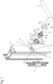
- Figure 1 is an exploded view of a sash according to the invention for a window or for a door with a frame profile 4 with a rotatable handle element 2.
- the sash has a lower rosette 21 with a contact surface 29 on which projections 26 are arranged.
- a bearing flange 22 is rotatably mounted on the lower rosette, to which the handle element 2 is fixed in a rotationally fixed manner, so that the handle element 2 is mounted on the lower rosette 21 so as to be rotatable about an axis H.
- the handle element 2 is fixed here in particular to the bearing flange 22 by means of a fastening means 28 designed as a screw.
- the frame profile 4 in Figure 1 has a recess 1 with a shape deviating from the circular shape.
- the recess 1 is preferably milled or punched into the frame profile 4.
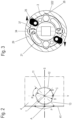
- the recess 1 is in Figure 2 shown enlarged. It has a predominantly circular inner geometry 12, which essentially has a diameter D, in particular from 20 mm to 35 mm, preferably from 25 mm to 30 mm and particularly preferably from 28 mm to 29 mm.
- the recess 1 also has several notches 13, each of which protrudes radially beyond the inner geometry 12 with a maximum depth C of in particular from 0.5 mm to 3 mm, preferably from 1 mm to 2 mm and particularly preferably from 1.1 mm to 1.2 mm.
- the notches 13 each have an outline which corresponds to at least one Section of a circle with a diameter of in particular 4 mm to 12 mm, preferably from 6 mm to 10 mm and particularly preferably from about 8 mm or exactly 8 mm.
- the notches 13 are therefore each designed in the shape of a circular arc.
- the respective circular arc preferably has a radian measure of ⁇ /2 radians to 3 ⁇ /2 radians and particularly preferably from 3 ⁇ /4 radians to ⁇ radians.
- a diameter B of an outermost circumference of the recess 1, which is a circle adjacent to the outermost point of the notches 13, is in particular from 20 mm to 35 mm, preferably from 25 mm to 30 mm and particularly preferably from 28 mm to 29 mm, wherein the diameter B is larger than the diameter D.
- the recess 1 has an axis of symmetry S, so that half of the notches 13 are located on each side of the axis of symmetry S, wherein a length of a circular arc lying on both sides of the recess 1 between the respective halves of the notches 13, through the center of which the axis of symmetry S runs, which extends in particular horizontally, is greater than a length of circular arcs lying between the half of the notches 13 lying on the corresponding side of the axis of symmetry S.
- Circular arcs that start from the respective center of the circles, of which the notches 13 are a part, preferably have a radian measure of ⁇ /5 radians to ⁇ /3 radians and particularly preferably of ⁇ /4 radians.
- a circular arc of the circular inner geometry 12 preferably has a radian measure of ⁇ /4 radians to ⁇ /2 radians and particularly preferably of ⁇ /3 radians.
- the recess 1 in particular also has a vertically extending axis of symmetry V.
- the circular arcs running between all notches 13 are arranged concentrically, so that they form the predominantly circular inner geometry 12 of the recess 1.
- the recess 1 optionally has predominantly the shape of a rosette.
- the recess 1 is as in Figure 1 or 2 with a smallest distance A of in particular 1 mm to 2.5 mm and preferably 1.2 mm to 1.4 mm from a nearest outer edge 41 of the frame profile 4.
- the lower rosette 21 rests against a base 35 of the holding element 3.
- the projections 26 on the contact surface 29 engage in several receptacles 33 in the inner side 31 of the holding element 3.
- the outline of the outer side 32 of the holding element 3 in an area held in the recess 1 essentially corresponds, in particular the projection 321, to an outline of an inner side 11 of the recess 1.
- the holding element 3 is held in the recess 1 in a plane that runs parallel to the plane of the circular inner geometry 12, essentially without play.
- FIG 3 is a cross-section of the lower rosette 21 from Figure 1 shown, which is inserted into the holding element 3, wherein the contact surface 29 has the described projections 26, which engage in the receptacles 33 in the holding element 3.
- the lower rosette 21 is essentially fastened to the holding element 3 by means of two fastening means 25.
- the fastening means 25 have a pivotable area, which can be pivoted into an opening 37 in the shell 322 of the holding element 3 and which secures the lower rosette 21 against axial withdrawal from the holding element 3.
- the outer side 32 of the holding element 3 has according to Figure 1 at least five projections 36 and preferably at least six projections 36 and in particular exactly six projections 36.
- An outline of the projections 36 corresponds to the notches 13.
- the frame profile 4 has a web which has a width T of 1 mm to 5 mm and preferably of 2 mm to 4 mm in the insertion direction of the holding element 3.
- the lower rosette 21 is inserted into the shell-shaped holding element 3.
- the holding element 3 can preferably transmit a torque of in particular 80 Nm to 150 Nm, preferably from 90 Nm to 110 Nm and particularly preferably more than 100 Nm to the frame profile 4, wherein the holding element 3 is held in the recess 1 in a dimensionally stable and form-fitting and/or rotationally fixed manner, so that the requirements of the standard EN 13126-3:2012-02 are met, in particular without the handle element 2 twisting and/or preferably without the frame profile 4 deforming.
- the frame profile 4 and/or the holding element 3 and/or the handle element 2 and/or the lower rosette 21 and/or the bearing flange 22 is preferably made of metal and/or plastic, the metal comprising aluminum in particular.
- a rosette 24 can optionally be attached to the lower rosette.
Landscapes
- Engineering & Computer Science (AREA)
- Mechanical Engineering (AREA)
- Wing Frames And Configurations (AREA)
- Hooks, Suction Cups, And Attachment By Adhesive Means (AREA)
Abstract
Description
- Die vorliegende Erfindung betrifft einen Flügel für ein Fenster oder eine Tür mit den Merkmalen des Oberbegriffs des Anspruchs 1.
- Es gibt Fensterflügelrahmen oder Türblätter, die zum Öffnen oder Schließen einen Tür- oder Fensterdrücker aufweisen, der an einem Lagerflansch drehbar an dem Rahmen gehalten ist.
EP 3 760 816 A1 offenbart eine Haltevorrichtung für Tür oder Fensterdrücker, die eine Unterrosette aufweist, die mit einer Anlagefläche auf einer dem Rahmen zugewandten Seite auf der Oberfläche des Rahmens in einem Bereich nahe einem Rand des Rahmens mittels zweier Schrauben montiert ist. Hier besteht der Nachteil, dass über die Unterrosette ein an dem Drücker angewandtes Drehmoment über die Schrauben auf einen kleinen Bereich des Rahmens überträgt, sodass in der Nähe des Randes hohe Kräfte auf den Rahmen einwirken. Hierdurch wird eine minimal erreichbare Breite des Rahmens verringert, da er dem Drehmoment standhalten muss. -
EP 3 680 423 A2 zeigt eine Drehvorrichtung für Tür- oder Fenstergriffe, mit einer Unterrosette die eine von der Kreisform abweichende Form aufweist, die in eine Aussparung in einem Tür- oder Fensterflügel einsteckbar ist. Durch das unmittelbare Einstecken der Unterrosette in den Flügel kann dieser Stand der Technik zwar einen sehr kompakten Aufbau der Drehvorrichtung ermöglichen, hier besteht aber wie beiEP 3 760 816 A1 das Problem, dass die Kraft, die von dem Griff über die Rosette unmittelbar auf den Flügel übertragen wird zu hoch für schmale Fenster- oder Türflügel ist. -
WO 2018/224294 A1 zeigt einen kreisförmigen und schalenförmigen Adapter zur Montage eines Türgriffs an einem Fensterrahmen. Der Adapter ist in eine kreisförmige Aussparung in dem Flügel eingesetzt. In den Adapter ist ein Basiskörper eingesteckt, der schwenkbare Klemmelemente aufweist, die einen Teil des Fensterrahmens hinter der Aussparung hintergreifen und den Griff so gegen ein axiales Herausziehen sichern. Der Adapter ist in den Fensterrahmen eingeschraubt und weist für eine Verdrehsicherung von der Unterseite hervorstehende Zapfen auf, die in einen hinter der Aussparung in dem Flügel angeordneten Teil mit einem entsprechenden sternförmigen Ausschnitt einsetzbar sind. Die Zapfen führen allerdings zu einer sehr konzentrierten Kraftübertragung, sodass auch diese Vorrichtung nur für breite Fensterrahmen geeignet ist. Die Sternform erschwert außerdem die Herstellung der Vorrichtung und erfordert einen Prozess, der diese Formen präzise Herstellen und die entsprechenden Bauteile anschließend ineinanderfügen kann. - Aufgabe der vorliegenden Erfindung ist es, einen Flügel für ein Fenster oder eine Tür anzugeben, der mit einem Griffelement ausgestattet ist, das platzsparend ausgebildet sein kann, sodass eine Breite des Rahmens reduziert ist.
- Die vorliegende Erfindung löst diese Aufgabe mittels eines Flügels für ein Fenster oder eine Tür mit den Merkmalen des Anspruchs 1.
- Erfindungsgemäß umfasst der Flügel für ein Fenster oder eine Tür ein Rahmenprofil mit einem drehbaren Griffelement, der eine Unterrosette mit einer Anlagefläche aufweist, auf der Vorsprünge angeordnet sind. An der Unterrosette ist ein Lagerflansch drehbar gelagert, an dem das Griffelement drehfest fixiert ist. Das Rahmenprofil weist eine Aussparung mit einer von der Kreisform abweichenden Form auf, in der ein Halteelement zur Fixierung der Unterrosette mit einer Außenseite drehfest gehalten ist. Hierdurch kann ein an dem Griffelement angewendetes Drehmoment gleichmäßig auf das Rahmenprofil verteilt werden, sodass das Rahmenprofil platzsparend ausgebildet sein und ein ansprechendes Erscheinungsbild aufweisen kann. Darüber hinaus kann das Griffelement mittels des Haltelements mit geringem Abstand zu einem Randbereich des Rahmenprofils angeordnet sein, was zu einer weiter verbesserten Platzersparnis und einer verbesserten Handhabung des Griffelements führt.
- Formschlüssig im Sinne der vorliegenden Erfindung, bedeutet, dass die jeweiligen Bauteile in jeweils parallelen Ebenen der jeweiligen relevanten Abschnitte so aneinander angepasst sind, dass jeweils eines der Teile weitestgehend ohne Spiel in paralleler Richtung zu diesen Ebenen in dem jeweils anderen Teil angeordnet werden kann.
- Erfindungsgemäß ist das Halteelement schalenförmig ausgebildet, wobei die Unterrosette in das schalenförmig ausgebildete Halteelement eingesteckt ist. Hierdurch kann die Vorrichtung besonders platzsparend ausgebildet sein. In einer weiteren Ausführungsform können die Unterrosette und das Halteelement auch einteilig ausgebildet sein, was eine Montage vereinfachen kann.
- Insbesondere weist die Außenseite des Haltelements mindestens zwei Vorsprünge und bevorzugt mindestens sechs Vorsprünge und insbesondere genau sechs Vorsprünge auf, sodass ein über das Griffelement auf das Halteelement übertragenes Drehmoment gleichmäßig auf das Rahmenprofil übertragbar ist und sodass das Halteelement mit verbesserter Drehfestigkeit im Rahmenprofil gehalten sein kann, ohne dass sich das Rahmenprofil verformt und/oder wesentlich verformt.
- Im Wesentlichen kann die Aussparung einen Durchmesser von insbesondere 20 mm bis 35 mm, bevorzugt von 25 mm bis 30 mm und besonders bevorzugt von 28 mm bis 29 mm aufweisen, wobei der Durchmesser ein Durchmesser einer überwiegend kreisförmigen Innengeometrie und/oder ein Durchmesser eines äu-ßeren Umfangs der Aussparung ist, der vorzugsweise ein an der äußersten Stelle der Auskerbungen anliegender Kreis ist, sodass die Dimensionierung der Aussparung an das Halteelement angepasst sein kann. Der Durchmesser des äußeren Umfangs der Aussparung ist hierbei größer als der Durchmesser der kreisförmigen Innengeometrie.
- Die Aussparung kann insbesondere mehrere Auskerbungen aufweisen, sodass ein Umriss der Aussparung einem Umriss der Außenseite des Halteelements, das formschlüssig in die Aussparung eingesteckt ist, entspricht. Vorzugsweise weist die Aussparung im Wesentlichen eine Kreisform auf, wobei die Auskerbungen bevorzugt in der Form von Teilkreisen gestaltet sein können, die über die überwiegend kreisförmige Innengeometrie der Aussparung hinausragen, sodass die Aussparung eine von der Kreisform abweichende Form aufweist. Die Form der Aussparung kann so insbesondere der Form einer Rosette ähneln. Hierdurch kann über das Halteelement eine besonders vorteilhafte Kräfteverteilung auf das Rahmenprofil erreicht werden.
- In einer Ausführungsform stehen die Auskerbungen jeweils mit einer maximalen Tiefe von insbesondere 0,5 mm bis 3 mm, bevorzugt von 1 mm bis 2 mm und besonders bevorzugt von 1,1 m bis 1,2 mm über die Innengeometrie hervor, sodass das Halteelement besonders vorteilhaft und/oder passgenau ausgebildet sein kann.
- Die Auskerbungen weisen zur vorteilhaften Gestaltung der Aussparung jeweils bevorzugt einen Umriss auf, der mindestens einem Abschnitt eines Kreises, also eines Kreisbogens entsprechen kann, der vorzugsweise mit einem Durchmesser von 4 mm bis 12 mm, insbesondere von 6 mm bis 10 mm und bevorzugt verbracht Millimetern oder besonders bevorzugt von genau 8 mm entspricht. Der jeweilige Kreisbogen hat bevorzugt ein Bogenmaß von π/2 Radianten bis 3π/2 Radianten und besonders bevorzugt von 3π/4 Radianten bis π Radianten.
- Ein Umriss der Vorsprünge spricht insbesondere den Auskerbungen, sodass das Halteelement mit einem besonders stabilen Formschluss in der Aussparung angeordnet sein kann.
- Ein Umriss der Aussparung ist im Wesentlichen identisch zu einem Umriss der Außenseite des Halteelements ausgebildet, sodass das Halteelement ohne Spiel drehfest in der Aussparung gehalten werden kann. Die gesamte Anlagefläche kann beispielsweise drehfest und formschlüssig mit einer Innenseite des Halteelements in dasselbe eingesetzt sein. Alternativ ist es auch möglich, dass nur die Vorsprünge an dem Halteelement und/oder an der Unterrosette jeweils formschlüssig in der Aussparung und/oder dem Halteelement angeordnet sind. Hierdurch kann beispielsweise Material gespart werden.
- Das Rahmenprofil weist im Bereich der Aussparung einen Steg auf, der in Einsteckrichtung des Halteelements eine Breite von 1 mm bis 5 mm und bevorzugt von 2 mm bis 4 mm aufweist. Hierdurch kann das Rahmenprofil materialsparend und somit kostengünstig hergestellt sein.
- Vorzugsweise kann das Rahmenprofil im Bereich einer Auskerbung insbesondere einen Steg aufweisen, der mit einer Breite von 1 mm bis 10 mm und bevorzugt von 2 mm bis 7 mm in Einsteckrichtung des Halteelements ausgebildet ist. Der Steg kann eine zusätzliche Anlagefläche für das Halteelement ausbilden.
- Die Aussparung ist insbesondere mit einem kleinsten Abstand von insbesondere 1 mm bis 2,5 mm und bevorzugt von 1,2 mm bis 1,4 Millimeters von einer nächstliegenden Außenkante des Rahmenprofils angeordnet. Dies ermöglicht eine besonders platzsparende Ausbildung des Flügels.
- Für eine vorteilhafte Herstellung ist die Aussparung bevorzugt in das Rahmenprofil gefräst und/oder gestanzt.
- Für eine besonders vorteilhafte Gestaltung des Flügels ist das Rahmenprofil und/oder das Halteelement und/oder das Griffelement und/oder die Unterrosette und/oder der Lagerflansch vorzugsweise aus Metall und/oder Kunststoff ausgebildet, wobei das Metall insbesondere Aluminium umfasst. Dies ermöglicht eine kostengünstige Ausbildung der Bauteile.
- Zur Absicherung gegen ein axiales Herausziehen aus der Aussparung, ist das Halteelement vorzugsweise an einem an dem Rahmenprofil angeordneten Treibstangenbeschlag insbesondere mittels mindestens eines Befestigungsmittels, das bevorzugt mindestens eine Schraube sein kann, befestigt. Das Halteelement kann insbesondere auch oder alternativ durch Kleben oder Klemmen an dem Rahmenprofil und/oder dem Treibstangenbeschlag befestigt sein. Die Unterrosette und/oder das Halteelement können jeweils mittels mindestens eines Befestigungsmittels aneinander und/oder an der Aussparung befestigt sein. Die Befestigungsmittel können insbesondere Schrauben und/oder einen Innensechskant und/oder einen Innensechsrund umfassen und bevorzugt mindestens einen ausschwenkbaren Bereich aufweisen, der jeweils in eine Öffnung in dem Halteelement und/oder der Unterrosette einschwenkbar sein kann. Hierdurch können die Unterrosette und/oder das Halteelement gegen axiales Herausziehen gesichert werden.
- Zur verbesserten Absicherung ist das Halteelement so ausgebildet, dass es ein Drehmoment von insbesondere 80 Newtonmetern (Nm) bis 150 Nm, bevorzugt von 90 Nm bis 110 Nm und besonders bevorzugt von mehr als 100 Nm übertragen kann, wobei das Halteelement formstabil und formschlüssig und drehfest in der Aussparung gehalten werden kann, sodass die Erfordernisse der Norm DIN EN 13126-3:2012-02 erfüllt sind, insbesondere ohne dass sich das Griffelement verdreht. Hierdurch kann das Griffelement besonders nah an einem Randbereich des Rahmenprofils angeordnet sein, ohne dass ein entsprechendes Drehmoment zu einer Verformung des Rahmenprofils führt.
- Das Griffelement ist bevorzugt drehfest in dem Lagerflansch angeordnet, sodass das Griffelement und der Lagerflansch um eine Achse verdrehbar an dem Rahmenprofil montiert sind.
- Der Flügel, insbesondere das Griffelement, kann dabei ein Schloss aufweisen, mittels dem der Flügel und insbesondere das Griffelement ver- und entriegelbar ist. Das Schloss weist hierfür bevorzugt einen in dem Griffelement angeordneten Zylinder auf, in den ein Schlüssel einsteckbar ist. Mittels Verdrehens des Schlüssels kann das Schloss Ab- oder Aufgeschlossen werden und der Flügel so verriegelt, beziehungsweise entriegelt werden, was vorzugsweise durch eine hierzu passende Verhinderung oder Gestattung einer Verdrehung des Griffelements geschieht.
- Die vorliegende Erfindung wird nachfolgend anhand mehrerer Zeichnungen näher erläutert. Es zeigen:
- Figur 1
- eine Explosionsansicht eines erfindungsgemäßen Flügels;
- Figur 2
- eine Ansicht einer Aussparung gemäß
Figur 1 ; - Figur 3
- einen Querschnitt einer Unterrosette gemäß
Figur 1 ; - Figur 4
- eine Explosionsansicht eines erfindungsgemäßen Flügels gemäß einer weiteren Ausführungsform.
- In
Figur 1 ist eine Explosionsansicht eines erfindungsgemäßen Flügels für ein Fenster oder für eine Tür mit einem Rahmenprofil 4 mit einem drehbaren Griffelement 2 dargestellt. Der Flügel weist eine Unterrosette 21 mit einer Anlagefläche 29 auf, auf der Vorsprünge 26 angeordnet sind. Ein Lagerflansch 22 ist drehbar an der Unterrosette gelagert, an dem das Griffelement 2 drehfest fixiert ist, sodass das Griffelement 2 um eine Achse H drehbar an der Unterrosette 21 gelagert ist. Das Griffelement 2 ist hier insbesondere mittels eines als Schaube ausgebildeten Befestigungsmittels 28 an dem Lagerflansch 22 fixiert. In den Lagerflansch 22 ist ein als Vierkant ausgebildeter Bolzen 23, der insbesondere einen viereckigen Querschnitt aufweist, drehfest in einen Tunnel 27 eingesteckt, sodass ein Verdrehen des Griffelements 2 über den Lagerflansch 22 zu einer Verdrehung des Bolzens 23 führt, wodurch optional ein an dem Rahmenprofil 4 angeordneter Treibstangenbeschlag 5, der eine Nut aufweist, in die der Bolzen eingreifen kann, betätigt wird, mittels dem das Fenster oder die Tür verriegelbar ist. - Das Rahmenprofil 4 in
Figur 1 weist eine Aussparung 1 mit einer von der Kreisform abweichenden Form auf. Die Aussparung 1 ist vorzugsweise in das Rahmenprofil 4 gefräst oder gestanzt. - Die Aussparung 1 ist in
Figur 2 vergrößert dargestellt. Sie weist eine überwiegend kreisförmige Innengeometrie 12 auf, die im Wesentlichen einen Durchmesser D insbesondere von 20 mm bis 35 mm, bevorzugt von 25 mm bis 30 mm und besonders bevorzugt von 28 mm bis 29 mm aufweist. Die Aussparung 1 weist zudem mehrere Auskerbungen 13 auf, die jeweils mit einer maximalen Tiefe C von insbesondere 0,5 mm bis 3 mm, bevorzugt von 1 mm bis 2 mm und besonders bevorzugt von 1,1 mm bis 1,2 mm radial über die Innengeometrie 12 hervorstehen. Die Auskerbungen 13 weisen jeweils einen Umriss auf, der zumindest einem Abschnitt eines Kreises mit einem Durchmesser von insbesondere 4 mm bis 12 mm, bevorzugt von 6 mm bis 10 mm und besonders bevorzugt von etwa 8 mm oder genau 8 mm entspricht. Die Auskerbungen 13 sind also jeweils in der Form eines Kreisbogens ausgebildet. Der jeweilige Kreisbogen hat bevorzugt ein Bogenmaß von π/2 Radianten bis 3π/2 Radianten und besonders bevorzugt von 3π/4 Radianten bis π Radianten. Ein Durchmesser B eines äußersten Umfangs der Aussparung 1, der ein an der äußersten Stelle der Auskerbungen 13 anliegender Kreis ist, beträgt insbesondere von 20 mm bis 35 mm, bevorzugt von 25 mm bis 30 mm und besonders bevorzugt von 28 mm bis 29 mm, wobei der Durchmesser B größer ist als der Durchmesser D. - Vorzugsweise weist die Aussparung 1 eine Symmetrieachse S auf, sodass jeweils die Hälfte der Auskerbungen 13 auf jeder Seite der Symmetrieachse S liegt, wobei eine Länge eines auf beiden Seiten der Aussparung 1 zwischen den jeweiligen Hälften der Auskerbungen 13 liegenden Kreisbogens, durch deren Mitte die Symmetrieachse S verläuft, die sich insbesondere horizontal erstreckt, größer ist als eine Länge von Kreisbögen, die zwischen der jeweils auf der entsprechenden Seite der Symmetrieachse S liegenden Hälfte der Auskerbungen 13 liegen. Kreisbögen, die vom jeweiligen Mittelpunkt der Kreise, deren Teil die Auskerbungen 13 darstellen, ausgehen, weisen bevorzugt ein Bogenmaß von π/5 Radianten bis π/3 Radianten und besonders bevorzugt von π/4 Radianten auf. Zwischen den Mittelpunkten der jeweils äußeren Auskerbungen 13, die auf gegenüberliegenden Seiten der Symmetrieachse S liegen, weist ein Kreisbogen der kreisförmigen Innengeometrie 12 vorzugsweise ein Bogenmaß von π/4 Radianten bis π/2 Radianten und besonders bevorzugt von π/3 Radianten auf. Die Aussparung 1 weist insbesondere auch eine vertikal verlaufende Symmetrieachse V auf.
- Die zwischen allen Auskerbungen 13 verlaufenden Kreisbögen sind insbesondere konzentrisch angeordnet, sodass sie die überwiegend kreisförmige Innengeometrie 12 der Aussparung 1 ausbilden. Die Aussparung 1 weist optional vorwiegend die Form einer Rosette auf. Die Aussparung 1 ist wie in
Figur 1 oder2 mit einem kleinsten Abstand A von insbesondere 1 mm bis 2,5 mm und bevorzugt von 1,2 mm bis 1,4 mm von einer nächstliegenden Außenkante 41 des Rahmenprofils 4 angeordnet. - In die Aussparung 1 ist ein, insbesondere schalenförmiges, Halteelement 3 an einer Außenseite 32, insbesondere an der Außenseite 32 eines von einer Schale hervorstehenden Vorsprungs 321, formschlüssig und drehfest gehalten, in das die Anlagefläche 29 drehfest und formschlüssig mit einer Innenseite 31 des Halteelements 3 eingesetzt ist. Die Unterrosette 21 liegt an einem Boden 35 des Halteelements 3 an. Die Vorsprünge 26 auf der Anlagefläche 29 greifen hierbei in mehrere Aufnahmen 33 in der Innenseite 31 des Halteelements 3 ein. Der Umriss der Außenseite 32 des Halteelements 3 entspricht hierbei in einem in der Aussparung 1 gehaltenen Bereich im Wesentlichen, insbesondere des Vorsprungs 321, einem Umriss einer Innenseite 11 der Aussparung 1. Hierdurch ist das Halteelement 3 in einer Ebene, die parallel zu der Ebene der kreisförmigen Innengeometrie 12 verläuft, im Wesentlichen ohne Spiel in der Aussparung 1 gehalten.
- In
Figur 3 ist ein Querschnitt der Unterrosette 21 ausFigur 1 dargestellt, die in das Halteelement 3 eingesetzt ist, wobei die Anlagefläche 29 die beschriebenen Vorsprünge 26 aufweist, die in die Aufnahmen 33 in dem Halteelement 3 eingreifen. Die Unterrosette 21 ist im Wesentlichen mittels zweier Befestigungsmittel 25 an dem Halteelement 3 befestigt. Die Befestigungsmittel 25 weisen einen ausschwenkbaren Bereich auf, der jeweils in eine Öffnung 37 in der Schale 322 des Halteelements 3 einschwenkbar ist und der die Unterrosette 21 gegen axiales Herausziehen aus dem Halteelement 3 absichert. - Die Außenseite 32 des Haltelements 3 weist gemäß
Figur 1 mindestens fünf Vorsprünge 36 und bevorzugt mindestens sechs Vorsprünge 36 und insbesondere genau sechs Vorsprünge 36 auf. Ein Umriss der Vorsprünge 36 entspricht den Auskerbungen 13. Im Bereich der Aussparung 1 weist das Rahmenprofil 4 einen Steg auf, der in Einsteckrichtung des Halteelements 3 eine Breite T von 1 mm bis 5 mm und bevorzugt von 2 mm bis 4 mm aufweist. Die Unterrosette 21 ist in das schalenförmig ausgebildete Halteelement 3 eingesteckt. - Der Boden 35 ist des Halteelementes 3 ist im Bereich des Vorsprungs 321 in der Ebene der Aussparung 1 angeordnet und die Außenseite 32 steht im Bereich der Schale 322 von dem Rahmenprofil 4 hervor.
- Zur Absicherung gegen ein axiales Herausziehen aus der Aussparung 1 ist das Halteelement 3 an einem an dem Rahmenprofil 4 angeordneten Treibstangenbeschlag 5 insbesondere mittels zweier Schraube 34 befestigt, wobei vorzugsweise auch die Unterrosette 21 mittels zweier Befestigungsmittel 25 an dem Halteelement 3 befestigt sind.
- Das Halteelement 3 kann vorzugsweise ein Drehmoment von insbesondere 80 Nm bis 150 Nm, bevorzugt von 90 Nm bis 110 Nm und besonders bevorzugt von mehr als 100 Nm auf das Rahmenprofil 4 übertragen, wobei das Halteelement 3 formstabil und formschlüssig und/oder drehfest in der Aussparung 1 gehalten wird, sodass die Erfordernisse der Norm EN 13126-3:2012-02 erfüllt sind, insbesondere ohne dass sich das Griffelement 2 verdreht und/oder bevorzugt ohne dass sich das Rahmenprofil 4 verformt.
- Das Rahmenprofil 4 und/oder das Halteelement 3 und/oder das Griffelement 2 und/oder die Unterrosette 21 und/oder der Lagerflansch 22 ist bevorzugt aus Metall und/oder Kunstsoff ausgebildet, wobei das Metall insbesondere Aluminium umfasst. Eine Rosette 24 kann optional auf die Unterrosette aufgesteckt sein.
-
Fig. 4 zeigt einen Flügel gemäß einer weiteren Ausführungsform der vorliegenden Erfindung, wobei hier der Flügel mittels eines Schlosses 6 verriegelbar ist, das einen Zylinder 61 mit einem Schlitz 62 aufweist, in den ein insbesondere verdrehbarer Schlüssel 63 zum Abschließen oder Aufschließen des Schlosses 6, also zum Ver- und Entriegeln des Flügels, insbesondere des Griffelements 2, einsteckbar ist. -
- 1
- Aussparung
- 11
- Innenseite
- 12
- Innengeometrie
- 13
- Auskerbung
- 13
- Auskerbungen
- 2
- Griffelement
- 21
- Unterrosette
- 22
- Lagerflansch
- 23
- Bolzen
- 24
- Rosette
- 25
- Befestigungsmittel
- 26
- Vorsprung
- 27
- Tunnel
- 28
- Befestigungsmittel
- 29
- Anlagefläche
- 3
- Halteelement
- 31
- Innenseite
- 32
- Außenseite
- 321
- Vorsprung
- 322
- Schale
- 33
- Aufnahme
- 34
- Schraube
- 35
- Boden
- 36
- Vorsprung
- 37
- Öffnung
- 4
- Rahmenprofil
- 41
- Außenkante
- 5
- Treibstangenbeschlag
- 6
- Schloss
- 61
- Zylinder
- 62
- Schlitz
- 63
- Schlüssel
- A
- Abstand
- B
- Durchmesser
- C
- Tiefe
- D
- Durchmesser H Achse
- P
- Kreisbogen
- S
- Symmetrieachse
- T
- Breite
- V
- Symmetrieachse
Claims (14)
- Flügel für ein Fenster oder eine Tür mit einem Rahmenprofil (4) mit einem drehbaren Griffelement (2), der eine Unterrosette (21) mit einer Anlagefläche (29) aufweist, auf der Vorsprünge (26) angeordnet sind, wobei an der Unterrosette (21) ein Lagerflansch (22) drehbar gelagert ist, an dem das Griffelement (2) drehfest fixiert ist, wobei das Rahmenprofil (1) eine Aussparung (1) aufweist, in der ein schalenförmig ausgebildetes Halteelement (3) zur Fixierung der Unterrosette (21), die in das Halteelement (3) eingesteckt ist, mit einer Außenseite (32) drehfest gehalten ist, dadurch gekennzeichnet, dass die Aussparung eine von der Kreisform abweichende Form aufweist.
- Flügel nach Anspruch 1, dadurch gekennzeichnet, dass die Außenseite (32) des Haltelements (3) mindestens zwei Vorsprünge (36) und bevorzugt mindestens sechs Vorsprünge (36) und insbesondere genau sechs Vorsprünge (36) aufweist.
- Flügel nach Anspruch 1 oder 2, dadurch gekennzeichnet, dass die Aussparung (1) im Wesentlichen einen Durchmesser insbesondere von 20 mm bis 35 mm, bevorzugt von 25 mm bis 30 mm und besonders bevorzugt von 28 mm bis 29 mm aufweist, wobei der Durchmesser ein Durchmesser (D) einer überwiegend kreisförmigen Innengeometrie (12) und/oder ein Durchmesser (B) eines äußersten Umfangs der Aussparung (1) ist.
- Flügel nach einem der vorgehenden Ansprüche, dadurch gekennzeichnet, dass die Aussparung (1) mehrere Auskerbungen (13) aufweist, sodass ein Umriss der Aussparung (1) einem Umriss der Außenseite (32) des Halteelements (3), das formschlüssig in die Aussparung (2) eingesteckt ist, entspricht.
- Flügel nach Anspruch 4, dadurch gekennzeichnet, dass die Auskerbungen (13) jeweils mit einer maximalen Tiefe (C) von insbesondere 0,5 mm bis 3 mm, bevorzugt von 1 mm bis 2 mm und besonders bevorzugt von 1,1 mm bis 1,2 mm über die Innengeometrie (12) hervorstehen.
- Flügel nach Anspruch 4 oder 5, dadurch gekennzeichnet, dass die Auskerbungen (13) jeweils einen Umriss aufweisen, der zumindest einem Abschnitt eines Kreises mit einem Durchmesser von insbesondere 4 mm bis 12 mm, bevorzugt von 6 mm bis 10 mm und besonders bevorzugt von etwa 8 mm oder genau 8 mm entspricht.
- Flügel nach einem der vorgehenden Ansprüche, dadurch gekennzeichnet, dass ein Umriss der Vorsprünge (36) den Auskerbungen (13) entspricht.
- Flügel nach einem der vorgehenden Ansprüche, dadurch gekennzeichnet, dass ein Umriss der Aussparung (1) im Wesentlichen identisch zu einem Umriss der Außenseite (32) des Halteelements (3) ist, sodass das Halteelement ohne Spiel drehfest in der Aussparung gehalten werden kann.
- Flügel nach einem der vorgehenden Ansprüche, dadurch gekennzeichnet, dass das Rahmenprofil (4) im Bereich der Aussparung (1) einen Steg aufweist, der in Einsteckrichtung des Halteelements (3) eine Breite (T) von 1 mm bis 5 mm und bevorzugt von 2 mm bis 4 mm aufweist.
- Flügel nach einem der vorgehenden Ansprüche, dadurch gekennzeichnet, dass die Aussparung (1) mit einem kleinsten Abstand (A) von insbesondere 1 mm bis 2,5 mm und bevorzugt von 1,2 mm bis 1,4 mm von einer nächstliegenden Außenkante (41) des Rahmenprofils (4) angeordnet ist.
- Flügel nach einem der vorgehenden Ansprüche, dadurch gekennzeichnet, dass die Aussparung (1) in das Rahmenprofil (4) gefräst und/oder gestanzt ist.
- Flügel nach einem der vorgehenden Ansprüche, dadurch gekennzeichnet, dass das Rahmenprofil (4) und/oder das Halteelement (3) und/oder das Griffelement (2) und/oder die Unterrosette (21) und/oder der Lagerflansch (22) aus Metall und/oder Kunstsoff ausgebildet ist, wobei das Metall insbesondere Aluminium umfasst.
- Flügel nach einem der vorgehenden Ansprüche, dadurch gekennzeichnet, dass das Halteelement (3) zur Absicherung gegen ein axiales Herausziehen aus der Aussparung (1) an einem an dem Rahmenprofil (4) angeordneten Treibstangenbeschlag (5) insbesondere mittels mindestens einer Schraube (34) befestigt ist.
- Flügel nach einem der vorgehenden Ansprüche, dadurch gekennzeichnet, dass das Halteelement (3) ein Drehmoment von insbesondere 80 Nm bis 150 Nm, bevorzugt von 90 Nm bis 110 Nm und besonders bevorzugt von mehr als 100 Nm auf das Rahmenprofil (4) übertragen kann, wobei das Halteelement (3) formstabil und formschlüssig und/oder drehfest in der Aussparung (1) gehalten werden kann, sodass die Erfordernisse der Norm DIN EN 13126-3:2012-02 erfüllt sind.
Applications Claiming Priority (1)
| Application Number | Priority Date | Filing Date | Title |
|---|---|---|---|
| DE102023109375.4A DE102023109375A1 (de) | 2023-04-13 | 2023-04-13 | Flügel für ein Fenster oder eine Tür |
Publications (2)
| Publication Number | Publication Date |
|---|---|
| EP4450738A1 true EP4450738A1 (de) | 2024-10-23 |
| EP4450738B1 EP4450738B1 (de) | 2025-06-18 |
Family
ID=91248047
Family Applications (1)
| Application Number | Title | Priority Date | Filing Date |
|---|---|---|---|
| EP24165473.0A Active EP4450738B1 (de) | 2023-04-13 | 2024-03-22 | Flügel für ein fenster oder eine tür |
Country Status (3)
| Country | Link |
|---|---|
| EP (1) | EP4450738B1 (de) |
| CN (1) | CN118933449A (de) |
| DE (1) | DE102023109375A1 (de) |
Citations (7)
| Publication number | Priority date | Publication date | Assignee | Title |
|---|---|---|---|---|
| WO2017103310A1 (es) * | 2015-12-14 | 2017-06-22 | Sistemas Técnicos Del Accesorio Y Componentes, S.L. | Manilla para puertas y ventanas y ventana o puerta asociada |
| WO2018224294A1 (de) | 2017-06-09 | 2018-12-13 | Franz Schneider Brakel Gmbh + Co Kg | Adapter zum einbau eines halteelements eines tür- oder fensterdrückers |
| WO2020074170A1 (de) * | 2018-10-08 | 2020-04-16 | Hermat-Metallwaren B. Porst GmbH | Griffsystem |
| WO2020126520A1 (de) * | 2018-12-21 | 2020-06-25 | Franz Schneider Brakel Gmbh + Co Kg | Vorrichtung zur fixierung eines tür- oder fensterdrückers |
| EP3680423A2 (de) | 2019-01-11 | 2020-07-15 | Eugen Notter GmbH Beschlägefabrik | Drehvorrichtung für fenster- und türgriffe |
| EP3760816A1 (de) | 2019-07-04 | 2021-01-06 | Franz Schneider Brakel GmbH + Co KG | Haltevorrichtung für einen tür- oder fensterdrücker |
| DE102021118158A1 (de) * | 2021-07-14 | 2023-01-19 | Hydro Extruded Solutions As | Schließeinrichtung für eine Drehvorrichtung |
Family Cites Families (1)
| Publication number | Priority date | Publication date | Assignee | Title |
|---|---|---|---|---|
| DE202015101329U1 (de) * | 2015-03-16 | 2016-06-20 | Franz Schneider Brakel Gmbh + Co Kg | Halteelement für einen Tür- oder Fensterdrücker und Anordnung eines Tür- oder Fensterdrückers an einer Aufnahmeöffnung eines Fensterrahmens, eines Türblatts oder dergleichen |
-
2023
- 2023-04-13 DE DE102023109375.4A patent/DE102023109375A1/de active Pending
-
2024
- 2024-03-22 EP EP24165473.0A patent/EP4450738B1/de active Active
- 2024-04-10 CN CN202410425569.6A patent/CN118933449A/zh active Pending
Patent Citations (7)
| Publication number | Priority date | Publication date | Assignee | Title |
|---|---|---|---|---|
| WO2017103310A1 (es) * | 2015-12-14 | 2017-06-22 | Sistemas Técnicos Del Accesorio Y Componentes, S.L. | Manilla para puertas y ventanas y ventana o puerta asociada |
| WO2018224294A1 (de) | 2017-06-09 | 2018-12-13 | Franz Schneider Brakel Gmbh + Co Kg | Adapter zum einbau eines halteelements eines tür- oder fensterdrückers |
| WO2020074170A1 (de) * | 2018-10-08 | 2020-04-16 | Hermat-Metallwaren B. Porst GmbH | Griffsystem |
| WO2020126520A1 (de) * | 2018-12-21 | 2020-06-25 | Franz Schneider Brakel Gmbh + Co Kg | Vorrichtung zur fixierung eines tür- oder fensterdrückers |
| EP3680423A2 (de) | 2019-01-11 | 2020-07-15 | Eugen Notter GmbH Beschlägefabrik | Drehvorrichtung für fenster- und türgriffe |
| EP3760816A1 (de) | 2019-07-04 | 2021-01-06 | Franz Schneider Brakel GmbH + Co KG | Haltevorrichtung für einen tür- oder fensterdrücker |
| DE102021118158A1 (de) * | 2021-07-14 | 2023-01-19 | Hydro Extruded Solutions As | Schließeinrichtung für eine Drehvorrichtung |
Also Published As
| Publication number | Publication date |
|---|---|
| CN118933449A (zh) | 2024-11-12 |
| DE102023109375A1 (de) | 2024-10-17 |
| EP4450738B1 (de) | 2025-06-18 |
Similar Documents
| Publication | Publication Date | Title |
|---|---|---|
| EP2163716B1 (de) | Schloss für eine Gleittür | |
| DE102005004000A1 (de) | Mitnehmer | |
| EP3543434B1 (de) | Drückerlagerung mit einem an dieser lösbar befestigten tür- oder fensterdrücker | |
| EP2796645B1 (de) | Riegelschloss eines Möbels | |
| DE102011078858A1 (de) | Zur verschieblichen Montage in einer einen Hinterschnitt aufweisenden Beschlagnut vorgesehenes Beschlagteil | |
| WO1993025789A1 (de) | Einstellbare halterung für lager- und gelenkzapfen, insbesondere zur verwendung an türen und toren | |
| EP3867465A1 (de) | Vorrichtung zur fixierung eines tür- oder fensterdrückers | |
| EP4450738B1 (de) | Flügel für ein fenster oder eine tür | |
| DE29713995U1 (de) | Türscharnier mit Feststeller | |
| DE20004943U1 (de) | Verriegelungsvorrichtung mit pilzförmigem Zapfen | |
| EP1780355B1 (de) | Betätigungsvorrichtung für die Haube eines Kraftfahrzeuges | |
| EP3363969B1 (de) | Betätigungshandhabe | |
| EP0318422A1 (de) | Einstellbares Gelenkband, insbesondere für Fenster und Türen | |
| WO2001025576A1 (de) | Zwischengetriebe für fenster-oder türbeschlag | |
| AT1463U1 (de) | Antriebsanordnung für verdrehbare lamellen eines eine fenster- oder türöffnung abdeckenden ladens | |
| DE102022120478A1 (de) | Betätigungshandhabe | |
| DE19736934C2 (de) | Verriegelungsbeschlag | |
| DE29615631U1 (de) | Sicherungseinrichtung | |
| EP1922467B1 (de) | Band für türen, fenster oder dergleichen | |
| EP4375456A1 (de) | Schliesssystem für türen oder fenster | |
| DE102023112864A1 (de) | Beschlag für Türen oder Fenster | |
| DE585035C (de) | Malschloss, dessen aus zwei Teilen bestehendes Gehaeuse nur bei entriegeltem Riegelbolzen geoeffnet werden kann | |
| DE20001006U1 (de) | Blendenkappe für einen Rolladenkasten | |
| EP1375795B1 (de) | Schub- oder Druckzylinderschlossanordnung | |
| WO2001034926A1 (de) | Winkelkorrekturhülse zur anpassung des einbauwinkels von drückern oder griffen an fenstern und türen |
Legal Events
| Date | Code | Title | Description |
|---|---|---|---|
| PUAI | Public reference made under article 153(3) epc to a published international application that has entered the european phase |
Free format text: ORIGINAL CODE: 0009012 |
|
| STAA | Information on the status of an ep patent application or granted ep patent |
Free format text: STATUS: THE APPLICATION HAS BEEN PUBLISHED |
|
| AK | Designated contracting states |
Kind code of ref document: A1 Designated state(s): AL AT BE BG CH CY CZ DE DK EE ES FI FR GB GR HR HU IE IS IT LI LT LU LV MC ME MK MT NL NO PL PT RO RS SE SI SK SM TR |
|
| STAA | Information on the status of an ep patent application or granted ep patent |
Free format text: STATUS: REQUEST FOR EXAMINATION WAS MADE |
|
| 17P | Request for examination filed |
Effective date: 20241115 |
|
| RBV | Designated contracting states (corrected) |
Designated state(s): AL AT BE BG CH CY CZ DE DK EE ES FI FR GB GR HR HU IE IS IT LI LT LU LV MC ME MK MT NL NO PL PT RO RS SE SI SK SM TR |
|
| GRAP | Despatch of communication of intention to grant a patent |
Free format text: ORIGINAL CODE: EPIDOSNIGR1 |
|
| STAA | Information on the status of an ep patent application or granted ep patent |
Free format text: STATUS: GRANT OF PATENT IS INTENDED |
|
| RIC1 | Information provided on ipc code assigned before grant |
Ipc: E05B 3/06 20060101ALI20250120BHEP Ipc: E05B 3/00 20060101AFI20250120BHEP |
|
| INTG | Intention to grant announced |
Effective date: 20250206 |
|
| GRAS | Grant fee paid |
Free format text: ORIGINAL CODE: EPIDOSNIGR3 |
|
| GRAA | (expected) grant |
Free format text: ORIGINAL CODE: 0009210 |
|
| STAA | Information on the status of an ep patent application or granted ep patent |
Free format text: STATUS: THE PATENT HAS BEEN GRANTED |
|
| P01 | Opt-out of the competence of the unified patent court (upc) registered |
Free format text: CASE NUMBER: APP_17837/2025 Effective date: 20250411 |
|
| AK | Designated contracting states |
Kind code of ref document: B1 Designated state(s): AL AT BE BG CH CY CZ DE DK EE ES FI FR GB GR HR HU IE IS IT LI LT LU LV MC ME MK MT NL NO PL PT RO RS SE SI SK SM TR |
|
| REG | Reference to a national code |
Ref country code: GB Ref legal event code: FG4D Free format text: NOT ENGLISH |
|
| REG | Reference to a national code |
Ref country code: CH Ref legal event code: EP |
|
| REG | Reference to a national code |
Ref country code: DE Ref legal event code: R096 Ref document number: 502024000069 Country of ref document: DE |
|
| REG | Reference to a national code |
Ref country code: CH Ref legal event code: EP |
|
| REG | Reference to a national code |
Ref country code: IE Ref legal event code: FG4D Free format text: LANGUAGE OF EP DOCUMENT: GERMAN |
|
| PG25 | Lapsed in a contracting state [announced via postgrant information from national office to epo] |
Ref country code: FI Free format text: LAPSE BECAUSE OF FAILURE TO SUBMIT A TRANSLATION OF THE DESCRIPTION OR TO PAY THE FEE WITHIN THE PRESCRIBED TIME-LIMIT Effective date: 20250618 |
|
| REG | Reference to a national code |
Ref country code: LT Ref legal event code: MG9D |
|
| PG25 | Lapsed in a contracting state [announced via postgrant information from national office to epo] |
Ref country code: GR Free format text: LAPSE BECAUSE OF FAILURE TO SUBMIT A TRANSLATION OF THE DESCRIPTION OR TO PAY THE FEE WITHIN THE PRESCRIBED TIME-LIMIT Effective date: 20250919 Ref country code: NO Free format text: LAPSE BECAUSE OF FAILURE TO SUBMIT A TRANSLATION OF THE DESCRIPTION OR TO PAY THE FEE WITHIN THE PRESCRIBED TIME-LIMIT Effective date: 20250918 |
|
| PG25 | Lapsed in a contracting state [announced via postgrant information from national office to epo] |
Ref country code: BG Free format text: LAPSE BECAUSE OF FAILURE TO SUBMIT A TRANSLATION OF THE DESCRIPTION OR TO PAY THE FEE WITHIN THE PRESCRIBED TIME-LIMIT Effective date: 20250618 |
|
| PG25 | Lapsed in a contracting state [announced via postgrant information from national office to epo] |
Ref country code: HR Free format text: LAPSE BECAUSE OF FAILURE TO SUBMIT A TRANSLATION OF THE DESCRIPTION OR TO PAY THE FEE WITHIN THE PRESCRIBED TIME-LIMIT Effective date: 20250618 |
|
| PG25 | Lapsed in a contracting state [announced via postgrant information from national office to epo] |
Ref country code: RS Free format text: LAPSE BECAUSE OF FAILURE TO SUBMIT A TRANSLATION OF THE DESCRIPTION OR TO PAY THE FEE WITHIN THE PRESCRIBED TIME-LIMIT Effective date: 20250918 |
|
| REG | Reference to a national code |
Ref country code: NL Ref legal event code: MP Effective date: 20250618 |
|
| PG25 | Lapsed in a contracting state [announced via postgrant information from national office to epo] |
Ref country code: LV Free format text: LAPSE BECAUSE OF FAILURE TO SUBMIT A TRANSLATION OF THE DESCRIPTION OR TO PAY THE FEE WITHIN THE PRESCRIBED TIME-LIMIT Effective date: 20250618 |
|
| PG25 | Lapsed in a contracting state [announced via postgrant information from national office to epo] |
Ref country code: NL Free format text: LAPSE BECAUSE OF FAILURE TO SUBMIT A TRANSLATION OF THE DESCRIPTION OR TO PAY THE FEE WITHIN THE PRESCRIBED TIME-LIMIT Effective date: 20250618 |
|
| PG25 | Lapsed in a contracting state [announced via postgrant information from national office to epo] |
Ref country code: PT Free format text: LAPSE BECAUSE OF FAILURE TO SUBMIT A TRANSLATION OF THE DESCRIPTION OR TO PAY THE FEE WITHIN THE PRESCRIBED TIME-LIMIT Effective date: 20251020 |
|
| PG25 | Lapsed in a contracting state [announced via postgrant information from national office to epo] |
Ref country code: IS Free format text: LAPSE BECAUSE OF FAILURE TO SUBMIT A TRANSLATION OF THE DESCRIPTION OR TO PAY THE FEE WITHIN THE PRESCRIBED TIME-LIMIT Effective date: 20251018 |
|
| PG25 | Lapsed in a contracting state [announced via postgrant information from national office to epo] |
Ref country code: SM Free format text: LAPSE BECAUSE OF FAILURE TO SUBMIT A TRANSLATION OF THE DESCRIPTION OR TO PAY THE FEE WITHIN THE PRESCRIBED TIME-LIMIT Effective date: 20250618 |
|
| PG25 | Lapsed in a contracting state [announced via postgrant information from national office to epo] |
Ref country code: CZ Free format text: LAPSE BECAUSE OF FAILURE TO SUBMIT A TRANSLATION OF THE DESCRIPTION OR TO PAY THE FEE WITHIN THE PRESCRIBED TIME-LIMIT Effective date: 20250618 |
|
| PG25 | Lapsed in a contracting state [announced via postgrant information from national office to epo] |
Ref country code: PL Free format text: LAPSE BECAUSE OF FAILURE TO SUBMIT A TRANSLATION OF THE DESCRIPTION OR TO PAY THE FEE WITHIN THE PRESCRIBED TIME-LIMIT Effective date: 20250618 |
|
| PG25 | Lapsed in a contracting state [announced via postgrant information from national office to epo] |
Ref country code: EE Free format text: LAPSE BECAUSE OF FAILURE TO SUBMIT A TRANSLATION OF THE DESCRIPTION OR TO PAY THE FEE WITHIN THE PRESCRIBED TIME-LIMIT Effective date: 20250618 |
|
| PG25 | Lapsed in a contracting state [announced via postgrant information from national office to epo] |
Ref country code: SK Free format text: LAPSE BECAUSE OF FAILURE TO SUBMIT A TRANSLATION OF THE DESCRIPTION OR TO PAY THE FEE WITHIN THE PRESCRIBED TIME-LIMIT Effective date: 20250618 |
|
| PG25 | Lapsed in a contracting state [announced via postgrant information from national office to epo] |
Ref country code: ES Free format text: LAPSE BECAUSE OF FAILURE TO SUBMIT A TRANSLATION OF THE DESCRIPTION OR TO PAY THE FEE WITHIN THE PRESCRIBED TIME-LIMIT Effective date: 20250618 |
|
| REG | Reference to a national code |
Ref country code: DE Ref legal event code: R097 Ref document number: 502024000069 Country of ref document: DE |
|
| PG25 | Lapsed in a contracting state [announced via postgrant information from national office to epo] |
Ref country code: DK Free format text: LAPSE BECAUSE OF FAILURE TO SUBMIT A TRANSLATION OF THE DESCRIPTION OR TO PAY THE FEE WITHIN THE PRESCRIBED TIME-LIMIT Effective date: 20250618 |
|
| PGFP | Annual fee paid to national office [announced via postgrant information from national office to epo] |
Ref country code: DE Payment date: 20260305 Year of fee payment: 3 |
|
| PGFP | Annual fee paid to national office [announced via postgrant information from national office to epo] |
Ref country code: AT Payment date: 20260301 Year of fee payment: 3 |
|
| PGFP | Annual fee paid to national office [announced via postgrant information from national office to epo] |
Ref country code: FR Payment date: 20260305 Year of fee payment: 3 |
|
| PLBE | No opposition filed within time limit |
Free format text: ORIGINAL CODE: 0009261 |
|
| STAA | Information on the status of an ep patent application or granted ep patent |
Free format text: STATUS: NO OPPOSITION FILED WITHIN TIME LIMIT |
|
| REG | Reference to a national code |
Ref country code: CH Ref legal event code: L10 Free format text: ST27 STATUS EVENT CODE: U-0-0-L10-L00 (AS PROVIDED BY THE NATIONAL OFFICE) Effective date: 20260430 |