EP4450451A2 - Materialhandhabungsfahrzeug mit einer kippgabelschlittenanordnung mit teleskopgabeln - Google Patents
Materialhandhabungsfahrzeug mit einer kippgabelschlittenanordnung mit teleskopgabeln Download PDFInfo
- Publication number
- EP4450451A2 EP4450451A2 EP24197754.5A EP24197754A EP4450451A2 EP 4450451 A2 EP4450451 A2 EP 4450451A2 EP 24197754 A EP24197754 A EP 24197754A EP 4450451 A2 EP4450451 A2 EP 4450451A2
- Authority
- EP
- European Patent Office
- Prior art keywords
- assembly
- fork
- mast
- tilt
- relative
- Prior art date
- Legal status (The legal status is an assumption and is not a legal conclusion. Google has not performed a legal analysis and makes no representation as to the accuracy of the status listed.)
- Pending
Links
Images










Classifications
-
- B—PERFORMING OPERATIONS; TRANSPORTING
- B66—HOISTING; LIFTING; HAULING
- B66F—HOISTING, LIFTING, HAULING OR PUSHING, NOT OTHERWISE PROVIDED FOR, e.g. DEVICES WHICH APPLY A LIFTING OR PUSHING FORCE DIRECTLY TO THE SURFACE OF A LOAD
- B66F9/00—Devices for lifting or lowering bulky or heavy goods for loading or unloading purposes
- B66F9/06—Devices for lifting or lowering bulky or heavy goods for loading or unloading purposes movable, with their loads, on wheels or the like, e.g. fork-lift trucks
-
- B—PERFORMING OPERATIONS; TRANSPORTING
- B66—HOISTING; LIFTING; HAULING
- B66F—HOISTING, LIFTING, HAULING OR PUSHING, NOT OTHERWISE PROVIDED FOR, e.g. DEVICES WHICH APPLY A LIFTING OR PUSHING FORCE DIRECTLY TO THE SURFACE OF A LOAD
- B66F9/00—Devices for lifting or lowering bulky or heavy goods for loading or unloading purposes
- B66F9/06—Devices for lifting or lowering bulky or heavy goods for loading or unloading purposes movable, with their loads, on wheels or the like, e.g. fork-lift trucks
- B66F9/075—Constructional features or details
- B66F9/08—Masts; Guides; Chains
- B66F9/10—Masts; Guides; Chains movable in a horizontal direction relative to truck
-
- B—PERFORMING OPERATIONS; TRANSPORTING
- B66—HOISTING; LIFTING; HAULING
- B66F—HOISTING, LIFTING, HAULING OR PUSHING, NOT OTHERWISE PROVIDED FOR, e.g. DEVICES WHICH APPLY A LIFTING OR PUSHING FORCE DIRECTLY TO THE SURFACE OF A LOAD
- B66F9/00—Devices for lifting or lowering bulky or heavy goods for loading or unloading purposes
- B66F9/06—Devices for lifting or lowering bulky or heavy goods for loading or unloading purposes movable, with their loads, on wheels or the like, e.g. fork-lift trucks
- B66F9/075—Constructional features or details
-
- B—PERFORMING OPERATIONS; TRANSPORTING
- B66—HOISTING; LIFTING; HAULING
- B66F—HOISTING, LIFTING, HAULING OR PUSHING, NOT OTHERWISE PROVIDED FOR, e.g. DEVICES WHICH APPLY A LIFTING OR PUSHING FORCE DIRECTLY TO THE SURFACE OF A LOAD
- B66F9/00—Devices for lifting or lowering bulky or heavy goods for loading or unloading purposes
- B66F9/06—Devices for lifting or lowering bulky or heavy goods for loading or unloading purposes movable, with their loads, on wheels or the like, e.g. fork-lift trucks
- B66F9/075—Constructional features or details
- B66F9/12—Platforms; Forks; Other load supporting or gripping members
- B66F9/122—Platforms; Forks; Other load supporting or gripping members longitudinally movable
-
- B—PERFORMING OPERATIONS; TRANSPORTING
- B66—HOISTING; LIFTING; HAULING
- B66F—HOISTING, LIFTING, HAULING OR PUSHING, NOT OTHERWISE PROVIDED FOR, e.g. DEVICES WHICH APPLY A LIFTING OR PUSHING FORCE DIRECTLY TO THE SURFACE OF A LOAD
- B66F9/00—Devices for lifting or lowering bulky or heavy goods for loading or unloading purposes
- B66F9/06—Devices for lifting or lowering bulky or heavy goods for loading or unloading purposes movable, with their loads, on wheels or the like, e.g. fork-lift trucks
- B66F9/075—Constructional features or details
- B66F9/12—Platforms; Forks; Other load supporting or gripping members
- B66F9/127—Working platforms
-
- B—PERFORMING OPERATIONS; TRANSPORTING
- B66—HOISTING; LIFTING; HAULING
- B66F—HOISTING, LIFTING, HAULING OR PUSHING, NOT OTHERWISE PROVIDED FOR, e.g. DEVICES WHICH APPLY A LIFTING OR PUSHING FORCE DIRECTLY TO THE SURFACE OF A LOAD
- B66F9/00—Devices for lifting or lowering bulky or heavy goods for loading or unloading purposes
- B66F9/06—Devices for lifting or lowering bulky or heavy goods for loading or unloading purposes movable, with their loads, on wheels or the like, e.g. fork-lift trucks
- B66F9/075—Constructional features or details
- B66F9/12—Platforms; Forks; Other load supporting or gripping members
- B66F9/14—Platforms; Forks; Other load supporting or gripping members laterally movable, e.g. swingable, for slewing or transverse movements
- B66F9/142—Movements of forks either individually or relative to each other
-
- B—PERFORMING OPERATIONS; TRANSPORTING
- B66—HOISTING; LIFTING; HAULING
- B66F—HOISTING, LIFTING, HAULING OR PUSHING, NOT OTHERWISE PROVIDED FOR, e.g. DEVICES WHICH APPLY A LIFTING OR PUSHING FORCE DIRECTLY TO THE SURFACE OF A LOAD
- B66F9/00—Devices for lifting or lowering bulky or heavy goods for loading or unloading purposes
- B66F9/06—Devices for lifting or lowering bulky or heavy goods for loading or unloading purposes movable, with their loads, on wheels or the like, e.g. fork-lift trucks
- B66F9/075—Constructional features or details
- B66F9/12—Platforms; Forks; Other load supporting or gripping members
- B66F9/14—Platforms; Forks; Other load supporting or gripping members laterally movable, e.g. swingable, for slewing or transverse movements
- B66F9/147—Whole unit including fork support moves relative to mast
-
- B—PERFORMING OPERATIONS; TRANSPORTING
- B66—HOISTING; LIFTING; HAULING
- B66F—HOISTING, LIFTING, HAULING OR PUSHING, NOT OTHERWISE PROVIDED FOR, e.g. DEVICES WHICH APPLY A LIFTING OR PUSHING FORCE DIRECTLY TO THE SURFACE OF A LOAD
- B66F9/00—Devices for lifting or lowering bulky or heavy goods for loading or unloading purposes
- B66F9/06—Devices for lifting or lowering bulky or heavy goods for loading or unloading purposes movable, with their loads, on wheels or the like, e.g. fork-lift trucks
- B66F9/075—Constructional features or details
- B66F9/12—Platforms; Forks; Other load supporting or gripping members
- B66F9/16—Platforms; Forks; Other load supporting or gripping members inclinable relative to mast
-
- B—PERFORMING OPERATIONS; TRANSPORTING
- B66—HOISTING; LIFTING; HAULING
- B66F—HOISTING, LIFTING, HAULING OR PUSHING, NOT OTHERWISE PROVIDED FOR, e.g. DEVICES WHICH APPLY A LIFTING OR PUSHING FORCE DIRECTLY TO THE SURFACE OF A LOAD
- B66F9/00—Devices for lifting or lowering bulky or heavy goods for loading or unloading purposes
- B66F9/06—Devices for lifting or lowering bulky or heavy goods for loading or unloading purposes movable, with their loads, on wheels or the like, e.g. fork-lift trucks
- B66F9/075—Constructional features or details
- B66F9/20—Means for actuating or controlling masts, platforms, or forks
- B66F9/205—Arrangements for transmitting pneumatic, hydraulic or electric power to movable parts or devices
-
- B—PERFORMING OPERATIONS; TRANSPORTING
- B66—HOISTING; LIFTING; HAULING
- B66F—HOISTING, LIFTING, HAULING OR PUSHING, NOT OTHERWISE PROVIDED FOR, e.g. DEVICES WHICH APPLY A LIFTING OR PUSHING FORCE DIRECTLY TO THE SURFACE OF A LOAD
- B66F9/00—Devices for lifting or lowering bulky or heavy goods for loading or unloading purposes
- B66F9/06—Devices for lifting or lowering bulky or heavy goods for loading or unloading purposes movable, with their loads, on wheels or the like, e.g. fork-lift trucks
- B66F9/075—Constructional features or details
- B66F9/20—Means for actuating or controlling masts, platforms, or forks
- B66F9/22—Hydraulic devices or systems
Definitions
- the present embodiments relate to a materials handling vehicle having a tilting fork carriage assembly with telescopic forks.
- Known materials handling vehicles include a power unit, a mast assembly, and a platform assembly that includes a fork carriage assembly coupled to the mast assembly for vertical movement relative to the power unit.
- the mast assembly and platform assembly may each include components that are controlled by a hydraulic working fluid, such as pressurized oil. Valves provided within hydraulic fluid circuits associated with the mast and platform assemblies may control the flow of the working fluid to the components for effecting various functions performed by the components, such as raising/lowering, traversing (also known as side shifting), and tilting of the fork carriage assembly.
- a materials handling vehicle comprises a load handling assembly including a mast assembly, and a fork carriage assembly comprising a fork support and at least one fork assembly, the at least one fork assembly including a first fork member, which is fixed to the fork support, and a second fork member.
- the materials handling vehicle further comprises a tilt assembly that tilts the fork support relative to the mast assembly such that a central axis of the at least one fork assembly is positionable in a plurality of different positions relative to a horizontal direction.
- the horizontal direction is defined with respect to a floor surface on which the vehicle is located.
- the materials handling vehicle further comprises a fork extension/retraction assembly that moves the second fork member relative to the first fork member in a first direction that is parallel to the central axis of the at least one fork assembly such that the fork extension/retraction assembly selectively moves the second fork member toward or away from the fork support in the first direction.
- the tilt assembly may comprise at least one tilt cylinder assembly including a cylinder and a piston.
- the extension of the piston may cause the tilt assembly to tilt the fork support relative to the mast assembly such that the fork support and the at least one fork assembly move into a tilt position, and a subsequent retraction of the piston may cause the tilt assembly to tilt the fork support relative to the mast assembly such that the fork support and the at least one fork assembly move into a home position.
- the at least one tilt cylinder assembly may have direction of elongation generally in the vertical direction.
- the materials handling vehicle may further comprise at least one cam assembly coupled to a corresponding tilt cylinder assembly, the cam assembly driven by the piston of the tilt cylinder assembly to tilt the fork support relative to the mast assembly.
- the cam assembly may comprise a cam weldment including a roller stud that is not concentric with a bearing surface of the cam weldment.
- Rotation of the cam weldment may cause the roller stud to move with an arc-like movement corresponding to the rotation of the cam weldment, wherein the arc-like movement tilts the fork support relative to the mast assembly.
- the fork support may be tiltable by the tilt assembly such that the central axis of the at least one fork assembly is positionable up to about plus (+) or minus (-) 5 degrees relative to the horizontal direction.
- the materials handling vehicle may further comprise a spacer structure that sets the central axis of the at least one fork assembly at a predetermined angle relative to the horizontal direction.
- the vehicle may comprise two fork assemblies.
- the second fork member may be positioned over the first fork member.
- the materials handling vehicle may further comprise a power unit, a platform assembly including an operator compartment, and a main mast assembly, wherein the mast assembly comprises an auxiliary mast assembly.
- the main mast assembly may vertically move the platform assembly and the auxiliary mast assembly relative to the power unit.
- a headlength of the load handling assembly which headlength is defined as a length from an outer surface of the fork support opposite to the mast assembly, to an inner surface of the tilt assembly, may be less than about ten (10) inches.
- the mast assembly may comprise a generally vertical first mast structure and a generally vertical second mast structure, wherein the second mast structure is rotatable relative to the first mast structure.
- the headlength may encompass the fork support, the second mast structure, and the tilt assembly.
- the tilt assembly may comprise at least one tilt cylinder assembly including a cylinder and a piston, the cylinder mounted to a flange that extends outwardly from the fork support toward the mast assembly.
- the headlength may encompass the fork support, the second mast structure, the at least one tilt cylinder assembly, and the flange.
- a materials handling vehicle comprises a power unit, a platform including an operator compartment, a load handling assembly including an auxiliary mast assembly, and a main mast assembly that moves the platform and load handling assembly relative to the power unit.
- the materials handling vehicle further comprises a fork carriage assembly comprising a fork support and first and second fork assemblies.
- Each of the first and second fork assemblies includes a first fork member, which is fixed to the fork support, and a second fork member.
- the materials handling vehicle further comprises a tilt assembly that tilts the fork support relative to the mast assembly such that a central axis of first and second fork assemblies is positionable in a plurality of different positions relative to a horizontal direction.
- the horizontal direction is defined with respect to a floor surface on which the vehicle is located.
- the materials handling vehicle further comprises a fork extension/retraction assembly that moves the second fork member of each fork assembly relative to the first fork member in a first direction that is parallel to the central axis of the first and second fork assemblies such that the fork extension/retraction assembly selectively moves the second fork members toward or away from the fork support in the first direction.
- the tilt assembly may comprise first and second tilt cylinder assemblies, each including a cylinder and a piston.
- the extension of the piston may cause the tilt assembly to tilt the fork support relative to the auxiliary mast assembly such that the fork support and the fork assemblies move into a tilt position, and a subsequent retraction of the piston may cause the tilt assembly to tilt the fork support relative to the mast assembly such that the fork support and the fork assemblies move into a home position.
- the tilt cylinder assemblies may each have direction of elongation generally in the vertical direction.
- the materials handling vehicle may further comprise first and second cam assemblies coupled to a corresponding tilt cylinder assembly, the cam assemblies driven by the piston of the corresponding tilt cylinder assembly to tilt the fork support relative to the auxiliary mast assembly.
- Each cam assembly may comprise a cam weldment including a roller stud that is not concentric with a bearing surface of the respective cam weldment.
- Rotation of each cam weldment may cause the corresponding roller stud to move with an arc-like movement corresponding to the rotation of the cam weldment, wherein the arc-like movement tilts the fork support relative to the auxiliary mast assembly.
- the fork support may be tiltable by the tilt assembly such that the central axis of the fork assemblies is positionable up to about plus (+) or minus (-) 5 degrees relative to the horizontal direction.
- the materials handling vehicle may further comprise a spacer structure that sets the central axis of the fork assemblies at a predetermined angle relative to the horizontal direction.
- the second fork member of each fork assembly may be positioned over the corresponding first fork member.
- a headlength of the load handling assembly which headlength is defined as a length from an outer surface of the fork support opposite to the auxiliary mast assembly, to an inner surface of the tilt assembly, may be less than about ten (10) inches.
- the auxiliary mast assembly may comprise a generally vertical first mast structure and a generally vertical second mast structure, wherein the second mast structure is rotatable relative to the first mast structure.
- the headlength may encompass the fork support, the second mast structure, and the tilt assembly.
- the tilt assembly may comprise first and second tilt cylinder assemblies, each including a cylinder and a piston, the cylinder of each tilt cylinder assembly mounted to a corresponding flange that extends outwardly from the fork support toward the auxiliary mast assembly.
- the headlength may encompass the fork support, the second mast structure, the tilt cylinder assemblies, and the flanges.
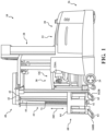
- the vehicle 10 comprises a turret stockpicker, such as the turret stockpicker disclosed in U.S. Patent No. 7,344,000 entitled "ELECTRONICALLY CONTROLLED VALVE FOR A MATERIALS HANDLING VEHICLE," assigned to the applicant, Crown Equipment Corporation, the entire disclosure of which is hereby incorporated by reference herein.
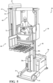
- the vehicle 10 includes a power unit 20, a platform assembly 30 including an operator compartment OC, and a load handling assembly 40.
- the power unit 20 includes a power source, such as a battery unit 22, a pair of load wheels 24, see Fig.
- the vehicle 10 further comprises a main mast assembly 28 coupled to the power unit 20 on which the platform assembly 30 moves vertically.
- the main mast assembly 28 comprises a first mast 28a fixedly coupled to the power unit 20, and a second mast 28b movably coupled to the first mast 28a, see Figs. 4 and 5 . While the illustrated main mast assembly 28 includes two masts 28a, 28b, the main mast assembly 28 may include additional or fewer masts.
- a main mast piston/cylinder unit 50 is provided in the first mast 28a for effecting vertical movement of the second mast 28b and the platform assembly 30 relative to the first mast 28a and the power unit 20, see Fig. 4 .
- a load handling assembly 40 (to be discussed in greater detail below) is mounted to the platform assembly 30; hence, the load handling assembly 40 moves with the platform assembly 30 when the main mast assembly 28 is raised or lowered.
- a cylinder 50a forming part of the piston/cylinder unit 50 is fixedly coupled to the power unit 20.
- a piston or ram 50b forming part of the piston/cylinder unit 50 is fixedly coupled to the second mast 28b such that movement of the piston 50b effects movement of the second mast 28b relative to the first mast 28a.
- the piston 50b comprises a pulley 50c on its distal end, which engages a pair of chains 52 and 54.
- One unit of vertical movement of the piston 50b results in two units of vertical movement of the platform assembly 30 and load handling assembly 40.
- Each chain 52, 54 is fixedly coupled at a first end 52a, 54a to the first mast 28a and coupled at a second end 52b, 54b to the platform assembly 30.
- upward movement of the piston 50b relative to the cylinder 50a effects upward movement of the platform assembly 30 and load handling assembly 40 via the pulley 50c pushing upwardly against the chains 52, 54.
- Downward movement of the piston 50b effects downward movement of the platform assembly 30 and load handling assembly 40. Movement of the piston 50b also effects movement of the second mast 28b.
- the load handling assembly 40 comprises an auxiliary mast assembly 41 including a first mast structure 42, which comprises a generally vertical mast structure that is movable back and forth transversely in a first direction relative to the platform assembly 30, as designated by an arrow D200 in Fig. 2 , via a traverse hydraulic motor 98, see also Figs. 3 , 4 and 14 .
- the auxiliary mast assembly 41 further comprises a second mast structure 44, which comprises a generally vertical mast structure that moves transversely with the first mast structure 42 and is also capable of rotating relative to the first mast structure 42 via first and second pivot piston/cylinder units 102a and 102b, see Fig. 14 .
- the second mast structure 44 is capable of rotating back and forth through an angle of about 180°.
- a fork carriage assembly 60 comprising a pair of forks 62 and a fork support 64.
- the fork carriage assembly 60 is capable of moving vertically relative to the second mast structure 44, as designated by an arrow 203 in Fig. 1 .
- Rotation of the second mast structure 44 relative to the first mast structure 42 permits an operator to position the forks 62 in one of at least a first position, illustrated in Figs. 1 , 2 and 4 , and a second position, illustrated in Fig. 3 , where the second mast structure 44 has been rotated through an angle of about 180° from its position shown in Figs. 1 , 2 and 4 .
- the fork carriage assembly 60 will be described in more detail below.
- the forks 62 comprise a first fork assembly 160 and a second fork assembly 162, although additional or fewer fork assemblies may be included.
- the first fork assembly 160 comprises a first fork member 160A, which is fixed to the fork support 64, and a second fork member 160B positioned over the first fork member 160A.
- the second fork member 160B is movable in the direction of the arrow D200 shown in Fig. 2 relative to the first fork member 160A via a first extension piston/cylinder unit 106a of a fork extension/retraction assembly 106 (see Fig. 14A ), the direction of the arrow D200 defining a direction of elongation of the first and second fork members 160A, 160B.
- the second fork assembly 162 comprises a first fork member 162A, which is fixed to the fork support 64, and a second fork member 162B.
- the second fork member 162B is movable in the direction of the arrow D200 shown in Fig. 2 relative to the first fork member 162A via a second extension piston/cylinder unit 106b of the fork extension/retraction assembly 106, see Fig. 14A , the direction of the arrow D200 defining a direction of elongation of the first and second fork members 162A, 162B.
- the second extension piston/cylinder unit 106b may be substantially similar to the first extension piston/cylinder unit 106a.
- the second fork members 160B and 162B move away from, i.e., extend out from, the fork support 64 and the first fork members 160A and 162A so as to define telescopic or extended forks.
- the first and second extension piston/cylinder units 106a and 106b of the fork extension/retraction assembly 106 are actuated so as to retract their pistons, the second fork members 160B and 162B move toward the fork support 64 and the first fork members 160A and 162A.
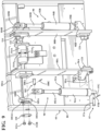
- a piston/cylinder unit 70 is provided in the second mast structure 44 for effecting vertical movement of the fork carriage assembly 60 relative to the second mast structure 44, see Fig. 6 .
- a cylinder 70a forming part of the piston/cylinder unit 70 is fixedly coupled to the second mast structure 44.
- a piston or ram 70b forming part of the unit 70 comprises a pulley 70c on its distal end, which engages a chain 72.
- One unit of vertical movement of the piston 70b results in two units of vertical movement of the fork carriage assembly 60.
- the chain 72 is fixedly coupled at a first end 72a to the cylinder 70a and fixedly coupled at a second end 72b to the fork support 64.
- the chain 72 extends from the cylinder 70a, over the pulley 70c and down to the fork support 64. Upward movement of the piston 70b effects upward movement of the fork carriage assembly 60 relative to the second mast structure 44, while downward movement of the piston 70b effects downward movement of the fork carriage assembly 60 relative to the second mast structure 44.
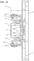
- Figs. 7-10 illustrate more detailed views of the fork carriage assembly 60, particularly the fork support 64.
- the fork support 64 comprises a frame 80 having a generally rectangular shape.
- the frame 80 provides the structural support for the forks 62 via a conventional rod or pin (not shown) that is coupled to the frame 80 at respective fork pivot locations 82A, 82B and extends through fork hanger openings 84A, 84B at the top of each of the forks 62.
- the forks 62 are pivotably supported to the fork support 64 at the fork pivot locations 82A, 82B, as will be discussed in greater detail herein.
- a backside of the frame 80 illustrated in Fig. 8 , includes a pair of generally vertically extending flanges 88A, 88B that extend outwardly from the frame 80 toward the auxiliary mast assembly 41.
- a tilt assembly 90 is provided for tilting the fork support 64 and the forks 62 relative to the auxiliary mast assembly 41.
- the tilt assembly 90 comprises first and second tilt cylinder assemblies 92A, 92B, each having a direction of elongation generally in the vertical direction, which vertical direction is perpendicular to a horizontal direction Hz (see Figs. 12A and 12B ), wherein the horizontal direction Hz is defined with respect to the floor surface on which the vehicle 10 is located.
- First and second cylinders 94A, 94B of the tilt cylinder assemblies 92A, 92B are coupled to mount units 96A, 96B, which are fixed to the frame 80 of the fork support 64 and to the respective flanges 88A, 88B.
- the cylinders 94A, 94B are coupled to the mount units 96A, 96B via first mounting structure 97 (only the first mounting structure 97 for the cylinder 94A is shown in Fig.
- the first mounting structure 97 for the other cylinder 94B is the same as the described mounting structure 97) that permits the cylinder assemblies 92A, 92B to pivot within slots 99A, 99B formed in the mount units 96A, 96B.
- the exemplary first mounting structure 97 illustrated in Fig. 9 comprises a pin 97A, e.g., a clevis pin, that extends through opposing bores formed in the mount unit 96A adjacent to the slot 99A and is received in an opening 97B within the first cylinder 94A.
- the pin 97A may be fixed in place with a cotter pin 97C as shown in Fig. 9 . It is understood that other suitable types of mounting structures can be used for pivotably supporting the cylinder assemblies 92A, 92B to the mount units 96A, 96B.
- First and second pistons or rams 102A, 102B of the tilt cylinder assemblies 92A, 92B are coupled to respective first and second cam assemblies 104A, 104B that are rotatable with respect to the flanges 88A, 88B.
- the cam assemblies 104A, 104B each include a cam lever arm 105A, 105B, which are pivotably coupled to the respective rams 102A, 102B via second mounting structure 103 (only the second mounting structure 103 for the first cam assembly 104A is shown in Fig. 9 and will be described herein, it being understood that the second mounting structure 103 for the second cam assembly 104B is the same as the described mounting structure 103).
- the exemplary second mounting structure 103 illustrated in Fig. 9 comprises a pin 108A, e.g., a clevis pin, that extends through opposing bores formed in the mount unit ram 102A and is received in an opening 108B within the cam lever arm 105A.
- the pin 108A may be fixed in place with a cotter pin 108C as shown in Fig. 9 . It is understood that other suitable types of mounting structures can be used for pivotably supporting the rams 102A, 102B to the cam lever arms 105A, 105B.
- the first cam assembly 104A will now be described, it being understood that the second cam assembly 104B is the same as the described first cam assembly 104A.
- the cam assembly 104A comprises a keeper plate 110 that is bolted to the cam lever arm 105A via bolts 112A, 112B.
- the keeper plate 110 prevents dirt/debris from entering the cam assembly 104A and couples the cam lever arm 105A to a cam weldment 114, i.e., the bolts 112A, 112B respectively extend through a spacer/washer structure 105A1, which is assembled onto the pin 108A, and a bore 105A2 formed in the cam lever arm 105A, 105B and are threaded into threaded openings 114A 1 , 114A 2 formed in the cam weldment 114A.
- the cam weldments 114 are coupled to respective cam rollers 120 (see Figs. 12A and 12B ) that move in a generally vertical direction within channels 121 defined by the second mast structure 44 of the auxiliary mast assembly 41.
- Movement of the cam assemblies 104A, 104B and the cam rollers 120 causes tilting of the fork support 64 and the forks 62 relative to the auxiliary mast assembly 41.
- a roller stud 122 of the cam weldment 114 upon which roller stud 122 the cam roller 120 is supported, is not concentric with the bearing surface of the cam weldment 114.
- the tilt cylinder assembly 92A is actuated to cause the ram 102A to extend or retract to thereby drive rotation of the cam lever arm 105A and the cam weldment 114
- the roller stud 122 moves with an arc-like movement corresponding to the rotation of the cam weldment 114.
- This arc-like movement causes the frame 80 of the fork support 64 and the forks 62 to tilt relative to the auxiliary mast assembly 41 such that a central axis C A (see Figs. 12A , 12B , and 13 ) of each of the fork assemblies 160, 162 is positionable in a plurality of different positions relative to the horizontal direction Hz, as will be described in greater detail below.
- the arc-like movement of the roller stud 122 effectively pushes the top of the frame 80 of the fork support 64 toward/away from the auxiliary mast assembly 41 when the first and second cylinders 94A, 94B of the tilt cylinder assemblies 92A, 92B are extended/retracted, i.e., the frame 80 of the fork support 64 pivots toward/away from the auxiliary mast assembly 41 at a pivot point defined by lower carriage/mast roller studs 124 coupled to the flanges 88A, 88B.
- a manifold 130 illustrated in Fig. 7 , is provided to supply hydraulic fluid to the first and second extension piston/cylinder units 106a, 106b of the fork extension/retraction assembly 106 and to the first and second tilt cylinder assemblies 92A, 92B of the tilt assembly 90 via flow path defining conduits or hoses, hereinafter referred to as "hydraulic hoses".
- flow path defining conduits or hoses hereinafter referred to as "hydraulic hoses”.
- a first hydraulic hose 132A provides hydraulic fluid to the first extension piston/cylinder unit 106a during a fork extend operation
- a second hydraulic hose 132B provides hydraulic fluid to the second extension piston/cylinder unit 106b during a fork extend operation
- a third hydraulic hose 132C provides hydraulic fluid to the second tilt cylinder assembly 92B during a tilt retract operation
- a fourth hydraulic hose 132D provides hydraulic fluid to the first tilt cylinder assembly 92A during a tilt retract operation
- a fifth hydraulic hose 132E provides hydraulic fluid to the second tilt cylinder assembly 92B during a tilt extend operation
- a sixth hydraulic hose 132F provides hydraulic fluid to the first extension piston/cylinder unit 106a during a fork retract operation
- a seventh hydraulic hose 132G provides hydraulic fluid to the first tilt cylinder assembly 92A during a tilt extend operation
- an eighth hydraulic hose 132H provides hydraulic fluid to the second extension piston/cylinder unit 106b during a fork retract operation.
- Additional ports 134A, 134B are provided in the manifold for main hydraulic fluid supply and return to a hydraulic fluid source (not shown) located on the vehicle 10. It is understood that other manifold configurations could be used, including using separate manifolds for one or more of the piston/cylinder units 106a, 106b and/or tilt cylinder assemblies 92A, 92B.
- a headlength H L of the load handling assembly 40 which headlength H L is defined as a length from an outer surface 64A of the fork support 64, i.e., a surface of the fork support 64 opposite to the second mast structure 44 of the auxiliary mast assembly 41, to a surface of the tilt assembly 90, i.e., an inner surface 92A1, 92B1 of the tilt cylinder assemblies 92A, 92B is less than about ten (10) inches and may be about 9.5 to about 9.75 inches.
- the inner surface 92A1, 92B1 of the tilt cylinder assemblies 92A, 92B may generally coincide with an inner surface 44A of the second mast structure 44 of the auxiliary mast assembly 41, i.e., a surface of the auxiliary mast assembly 41 opposite to the fork support 64, and an inner surface of the flanges 88A, 88B.
- the headlength H L encompasses the fork support 64, the second mast structure 44 of the auxiliary mast assembly 41, the tilt cylinder assemblies 92A, 92B, the flanges 88A, 88B, and the manifold 130, i.e., all of these structures are located within the headlength H L .
- the headlength H L of the load handling assembly 40 according to the present embodiment is believed to be significantly less than headlengths of prior art load handling assemblies that utilize different assemblies for effecting tilting of the fork support and forks.
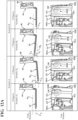
- Figs. 12A and 12B select positions of the fork support 64 and forks 62, along with the corresponding positions of the tilt cylinder assemblies 92A, 92B, cam assemblies 104A, 104B, and cam rollers 120 are shown. It is understood that the positions shown in Figs. 12A and 12B are exemplary and are meant to show select ones of many possible positions.
- scenario A corresponds to a configuration wherein a first spacer structure SP 1 (see Fig. 13 ) is provided to set a "home" position of the fork support 64 and forks 62 such that the central axis C A of each of the fork assemblies 160, 162 is generally parallel to the horizontal direction Hz.
- scenario B corresponds to a configuration wherein a second spacer structure SP 2 (see Fig.
- Scenario A 1 illustrated in Fig. 12A represents the home position of the fork support 64 and forks 62 with the first spacer structure SP 1 , wherein the central axis C A of each of the fork assemblies 160, 162 is generally parallel to the horizontal direction Hz.
- the forks 62 are provided in a retracted position in scenario A 1 , wherein the piston of the first and second extension piston/cylinder units 106a and 106b of the fork extension/retraction assembly 106 are in their retracted positions such that the second fork members 160B and 162B are located in close proximity to the fork support 64.
- the 12A represents a "tilt" position of the fork support 64 and forks 62 with the first spacer structure SP 1 , wherein the central axis C A of each of the fork assemblies 160, 162 is positioned at a third angle ⁇ 3 relative to the horizontal direction Hz.
- the third angle ⁇ 3 may be, for example, about -5 degrees.
- the forks 62 are provided in the retracted position in scenario A 2 .
- Scenario A 3 illustrated in Fig. 12B represents the home position of the fork support 64 and forks 62 with the first spacer structure SP 1 , wherein the central axis C A of each of the fork assemblies 160, 162 is generally parallel to the horizontal direction Hz.
- the forks 62 are provided in an extended position in scenario A 3 , wherein the piston of the first and second extension piston/cylinder units 106a and 106b of the fork extension/retraction assembly 106 are in their extended positions such that the second fork members 160B and 162B are spaced from the fork support 64, e.g., by about 3 inches, about 7.5 inches, or up to about 12 inches as desired.
- 12B represents the tilt position of the fork support 64 and forks 62 with the first spacer structure SP 1 , wherein the central axis C A of each of the fork assemblies 160, 162 is positioned at the third angle ⁇ 3 relative to the horizontal direction Hz.
- the forks 62 are provided in the extended position in scenario A 4 .
- Scenario B 3 illustrated in Fig. 12B represents the home position of the fork support 64 and forks 62 with the second spacer structure SP 2 , wherein the central axis C A of each of the fork assemblies 160, 162 is set at the first angle ⁇ 1 relative to the horizontal direction Hz.
- the forks 62 are provided in the extended position in scenario B 3 .
- the scenario B 4 illustrated in Fig. 12B represents the tilted position of the fork support 64 and forks 62 with the second spacer structure SP 2 , wherein the central axis C A of each of the fork assemblies 160, 162 is generally parallel to the horizontal direction Hz.
- the forks 62 are provided in the extended position in scenario B 4 .
- Scenario C shown in Fig. 13 is provided to illustrate another exemplary spacer structure SP 3 to define a home position of the fork support 64 and forks 62 at an additional angle relative to the horizontal direction H Z .
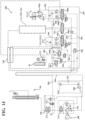
- FIG. 14 and 14A A schematic diagram of a hydraulic circuit 180 of the vehicle 10 is illustrated in Figs. 14 and 14A .
- the hydraulic circuit 180 in the embodiment shown comprises a manifold 182, which may be located in an upper portion 42A of the first mast structure 42 of the load handling assembly 40, see Fig. 2 .
- Exemplary valves in the illustrated manifold 182 include an auxiliary lower valve 190 that controls the flow of the working fluid out of the auxiliary hoist piston/cylinder unit 70 when a lowering command is being implemented; an auxiliary raise valve 194 that controls the flow of the working fluid into the auxiliary hoist piston/cylinder unit 70 when a raise command is being implemented; a traverse valve 196 that controls the flow of the working fluid to and/or from the traverse hydraulic motor 98 when a traverse command is being implemented; a pivot valve 200 that controls the flow of the working fluid to and/or from the first and second pivot piston/cylinder units 102a, 102b when a pivot command is being implemented; an extend valve 206 (see Fig.
- the load handler valve 204 controls a pressure level within the hydraulic manifold 182 such that the hydraulic fluid pressure downstream from the load handler valve 204 is at a sufficient level for proper operation of a selected one or more of the electronically controlled solenoid valves 194, 196, 200, 206, 212.
- the hydraulic circuit 180 comprises other electronically controlled solenoid-operated valves mounted in the power unit 20.
- an electronically controlled solenoid-operated non-proportional valve 270 is provided for blocking fluid flow out of the mast piston/cylinder unit 50 until the valve 270 is energized.
- An electronically controlled solenoid-operated non-proportional valve 271 is provided for blocking working fluid to the mast piston/cylinder unit 50 when not energized and allows fluid flow to the mast piston/cylinder unit 50 when the valve 271 is energized.
- An electronically controlled solenoid-operated non-proportional valve 272 is provided for blocking working fluid flow to the manifold 182 if working fluid is being provided to or exiting the mast piston/cylinder unit 50 and allows working fluid flow to the manifold 182 when the valve 272 is energized.
- An electronically controlled solenoid-operated proportional valve 274 is provided and functions as a load holding valve for the mast piston/cylinder unit 50 and must be energized when the mast piston/cylinder unit 50 is lowered such that the working fluid flows through the valve 274 back through a pump 310.
- An electronically controlled solenoid-operated, normally closed, non-proportional valve 171 is coupled to a base of the cylinder 70a of the auxiliary hoist piston/cylinder unit 70 and is energized by the controller 210 during a controlled descent of the piston 70b of the unit 70.
- the hydraulic circuit 180 additionally comprises a counterbalance retract valve 410 in communication with the tilt control valve 208.
- a load is present on the forks 62 (or just the weight of the forks 62 themselves), the fork support 64 will want to tilt down, rolling the cam weldments 114 backwards, and thus causing the cam lever arms 105A, 105B to push the tilt cylinder assemblies 92A, 92B in to their retracted position, which causes a load-induced pressure within the tilt cylinder assemblies 92A, 92B.
- FIGs. 15A and 15B two exemplary configurations for a pair of cam rollers 120, 120' and roller studs 122, 122' are respectively shown from above.
- the cam rollers 120, 120' and roller studs 122, 122' are located in respective channels 121, 121' defined by the second mast structures 44, 44' of the corresponding auxiliary mast assemblies 41, 41'.
- the cam rollers 120 are cylindrical in shape, having first and second side edges 120A, 120B that are respectively generally parallel to one another.
- the roller studs 122 and the cam rollers 120 supported thereon may be oriented at an angle ⁇ relative to a centerline C L extending between the spaced apart cam rollers 120, such that one of the side edges 120A of each cam roller 120 is generally flush with an inner surface 44A of the respective second mast structures 44 that define the corresponding channels 121.
- the angle ⁇ may be less than about 5 degrees.
- the roller studs 122' and the cam rollers 120' supported thereon may be generally parallel to a centerline C L extending between the spaced apart cam rollers 120.
- the cam rollers 120' illustrated in Fig. 15B are conical in shape, having first and second side edges 120A', 120B' that taper inwardly as the cam rollers 120' extend toward one another, such that the first and second side edges 120A', 120B' of the cam rollers 120' generally correspond to the shape of tapered inner surfaces 44A', 44B' of the respective second mast structures 44' that define the corresponding channels 121'.
- the conical shape of the cam rollers 120' shown in Fig. 15B may allow for more surface contact between the cam rollers 120' and the mast structure 44', resulting in smoother movement of the cam rollers 120' within the channels 121'.
Landscapes
- Engineering & Computer Science (AREA)
- Transportation (AREA)
- Structural Engineering (AREA)
- Civil Engineering (AREA)
- Life Sciences & Earth Sciences (AREA)
- Geology (AREA)
- Mechanical Engineering (AREA)
- Chemical & Material Sciences (AREA)
- Combustion & Propulsion (AREA)
- Forklifts And Lifting Vehicles (AREA)
Applications Claiming Priority (3)
| Application Number | Priority Date | Filing Date | Title |
|---|---|---|---|
| US201962854498P | 2019-05-30 | 2019-05-30 | |
| EP20733139.8A EP3976526B1 (de) | 2019-05-30 | 2020-05-28 | Materialhandhabungsfahrzeug mit kippgabelträgeranordnung und teleskopgabeln |
| PCT/US2020/034775 WO2020243214A1 (en) | 2019-05-30 | 2020-05-28 | Materials handling vehicle having tilting fork carriage assembly with telescopic forks |
Related Parent Applications (2)
| Application Number | Title | Priority Date | Filing Date |
|---|---|---|---|
| EP20733139.8A Division-Into EP3976526B1 (de) | 2019-05-30 | 2020-05-28 | Materialhandhabungsfahrzeug mit kippgabelträgeranordnung und teleskopgabeln |
| EP20733139.8A Division EP3976526B1 (de) | 2019-05-30 | 2020-05-28 | Materialhandhabungsfahrzeug mit kippgabelträgeranordnung und teleskopgabeln |
Publications (2)
| Publication Number | Publication Date |
|---|---|
| EP4450451A2 true EP4450451A2 (de) | 2024-10-23 |
| EP4450451A3 EP4450451A3 (de) | 2025-01-08 |
Family
ID=71094862
Family Applications (2)
| Application Number | Title | Priority Date | Filing Date |
|---|---|---|---|
| EP24197754.5A Pending EP4450451A3 (de) | 2019-05-30 | 2020-05-28 | Materialhandhabungsfahrzeug mit einer kippgabelschlittenanordnung mit teleskopgabeln |
| EP20733139.8A Active EP3976526B1 (de) | 2019-05-30 | 2020-05-28 | Materialhandhabungsfahrzeug mit kippgabelträgeranordnung und teleskopgabeln |
Family Applications After (1)
| Application Number | Title | Priority Date | Filing Date |
|---|---|---|---|
| EP20733139.8A Active EP3976526B1 (de) | 2019-05-30 | 2020-05-28 | Materialhandhabungsfahrzeug mit kippgabelträgeranordnung und teleskopgabeln |
Country Status (8)
| Country | Link |
|---|---|
| US (1) | US11591198B2 (de) |
| EP (2) | EP4450451A3 (de) |
| KR (1) | KR102893828B1 (de) |
| CN (1) | CN113853352B (de) |
| AU (1) | AU2020283562B2 (de) |
| CA (1) | CA3139743A1 (de) |
| MX (2) | MX2021014551A (de) |
| WO (1) | WO2020243214A1 (de) |
Families Citing this family (6)
| Publication number | Priority date | Publication date | Assignee | Title |
|---|---|---|---|---|
| DE102019109594A1 (de) * | 2019-04-11 | 2020-10-15 | Hubtex Maschinenbau Gmbh & Co. Kg | Flurförderzeug |
| DE102019006140A1 (de) * | 2019-08-30 | 2021-03-04 | Kaup GmbH & Co. KG Gesellschaft für Maschinenbau | Vorrichtung zum Transportieren eines Transportgutes und Verfahren |
| IT201900018926A1 (it) * | 2019-10-15 | 2021-04-15 | Elett 80 S P A | Apparato per azionare i supporti portaforche di un carrello elevatore |
| JP7658703B2 (ja) * | 2023-05-11 | 2025-04-08 | 三菱ロジスネクスト株式会社 | 無人フォークリフト |
| US12545379B2 (en) * | 2023-06-15 | 2026-02-10 | John Thomas San Giacomo, JR. | Boat lift locking apparatus |
| US12473182B2 (en) | 2024-01-08 | 2025-11-18 | Robert M. Chavez | Rearward mast forklift chassis |
Citations (1)
| Publication number | Priority date | Publication date | Assignee | Title |
|---|---|---|---|---|
| US7344000B2 (en) | 2004-09-23 | 2008-03-18 | Crown Equipment Corporation | Electronically controlled valve for a materials handling vehicle |
Family Cites Families (16)
| Publication number | Priority date | Publication date | Assignee | Title |
|---|---|---|---|---|
| US3387731A (en) * | 1967-01-04 | 1968-06-11 | Raymond Corp | Fork truck |
| US3726427A (en) * | 1971-08-25 | 1973-04-10 | Bygg Och Transportekonomie Ab | Lift trucks |
| DE2358923A1 (de) * | 1973-11-27 | 1975-06-05 | Fendt & Co Xaver | Flurfoerdergeraet nach art eines gabelstaplers |
| US3998345A (en) * | 1974-04-05 | 1976-12-21 | Missouri Research Laboratories, Inc. | Side loader for fork lift trucks |
| DE3730272A1 (de) * | 1987-09-09 | 1989-04-06 | Steinbock Gmbh | Stapler |
| GB2266700B (en) * | 1992-05-08 | 1995-06-21 | Lansing Linde Ltd | Industrial lift trucks and load lifting carriages therefor |
| JPH07228497A (ja) * | 1994-02-14 | 1995-08-29 | Toyota Autom Loom Works Ltd | フォークリフトのフォーク傾斜装置 |
| DE19525723A1 (de) * | 1995-07-14 | 1997-01-16 | Linde Ag | Flurförderzeug mit einem Hubgerüst |
| JP2003267687A (ja) * | 2002-03-14 | 2003-09-25 | Nippon Yusoki Co Ltd | フォークリフト |
| JP2004244144A (ja) * | 2003-02-12 | 2004-09-02 | Nippon Yusoki Co Ltd | フォークリフトのパレットロック装置 |
| JP4391173B2 (ja) * | 2003-09-10 | 2009-12-24 | 日本輸送機株式会社 | フォークのティルト構造 |
| JP4471147B2 (ja) * | 2003-09-11 | 2010-06-02 | 日本輸送機株式会社 | フォークリフトのサイドシフト装置 |
| JP4817223B2 (ja) * | 2005-03-02 | 2011-11-16 | 日本輸送機株式会社 | フォークリフト |
| EP2802527B1 (de) * | 2012-01-13 | 2017-09-13 | Crown Equipment Corporation | Aufwärmzeit für ein förderfahrzeug |
| JP5761727B1 (ja) * | 2014-08-20 | 2015-08-12 | ニチユ三菱フォークリフト株式会社 | フォークリフトの電動式ティルト装置 |
| US10640349B2 (en) * | 2018-02-02 | 2020-05-05 | Cascade Corporation | Tilting side-shifting carriage for a lift truck |
-
2020
- 2020-05-28 EP EP24197754.5A patent/EP4450451A3/de active Pending
- 2020-05-28 CA CA3139743A patent/CA3139743A1/en active Pending
- 2020-05-28 AU AU2020283562A patent/AU2020283562B2/en active Active
- 2020-05-28 US US16/885,402 patent/US11591198B2/en active Active
- 2020-05-28 KR KR1020217040831A patent/KR102893828B1/ko active Active
- 2020-05-28 CN CN202080038094.5A patent/CN113853352B/zh active Active
- 2020-05-28 MX MX2021014551A patent/MX2021014551A/es unknown
- 2020-05-28 EP EP20733139.8A patent/EP3976526B1/de active Active
- 2020-05-28 WO PCT/US2020/034775 patent/WO2020243214A1/en not_active Ceased
-
2021
- 2021-11-26 MX MX2025011695A patent/MX2025011695A/es unknown
Patent Citations (1)
| Publication number | Priority date | Publication date | Assignee | Title |
|---|---|---|---|---|
| US7344000B2 (en) | 2004-09-23 | 2008-03-18 | Crown Equipment Corporation | Electronically controlled valve for a materials handling vehicle |
Also Published As
| Publication number | Publication date |
|---|---|
| US20200377352A1 (en) | 2020-12-03 |
| AU2020283562A1 (en) | 2021-11-11 |
| EP3976526B1 (de) | 2024-10-09 |
| CA3139743A1 (en) | 2020-12-03 |
| EP3976526A1 (de) | 2022-04-06 |
| CN113853352B (zh) | 2023-05-12 |
| CN113853352A (zh) | 2021-12-28 |
| MX2025011695A (es) | 2025-11-03 |
| KR102893828B1 (ko) | 2025-12-03 |
| WO2020243214A1 (en) | 2020-12-03 |
| US11591198B2 (en) | 2023-02-28 |
| EP4450451A3 (de) | 2025-01-08 |
| MX2021014551A (es) | 2022-01-06 |
| KR20220016102A (ko) | 2022-02-08 |
| AU2020283562A8 (en) | 2021-11-18 |
| AU2020283562B2 (en) | 2026-02-12 |
Similar Documents
| Publication | Publication Date | Title |
|---|---|---|
| EP3976526B1 (de) | Materialhandhabungsfahrzeug mit kippgabelträgeranordnung und teleskopgabeln | |
| AU2009291731B2 (en) | Monomast for a materials handling vehicle | |
| US5383758A (en) | Load positioning arm | |
| CA2203711C (en) | Boom hoist cylinder crane | |
| US2645372A (en) | Material handling apparatus | |
| US6062405A (en) | Hydraulic boom hoist cylinder crane | |
| US3762588A (en) | Front and lateral loading mechanism | |
| EP2116442A1 (de) | Gabelanordnungshebemechanismus | |
| US3378103A (en) | Aerial platforms | |
| EP1531141A1 (de) | Transportabler Gabelhubwagen | |
| KR101984667B1 (ko) | 갠트리 크레인 | |
| US4954041A (en) | Triple section telescopic boom materials handling vehicle | |
| US2755939A (en) | Hydraulic crane | |
| US5088880A (en) | Fluid operated fork positioning control system | |
| KR102605424B1 (ko) | 소형 크레인 | |
| RU2768058C1 (ru) | Малогабаритный электропогрузчик со стреловым грузоподъемным устройством | |
| US5496146A (en) | Steel slab and coil carrier | |
| EP1222134B1 (de) | Vorrichtung in einem hydraulichen hebezug | |
| IT201800006159A1 (it) | Carrello industriale semovente dotato di forche ad assetto variabile | |
| DE102015000934A1 (de) | Vorrichtung zum Transport und/oder zur zumindest vorübergehenden Lagerung eines Hubfahrzeugs und Verfahren zur Verwendung einer Vorrichtung zum Transport und/oder zur zumindest vorübergehenden Lagerung eines Hubfahrzeugs | |
| DE1531222A1 (de) | Vorrichtung an einer Maschine oder fuer eine Maschine zur Handhabung oder zur Befoerderung schwerer Lasten | |
| DE7004530U (de) | Radnontage-hubwagen. |
Legal Events
| Date | Code | Title | Description |
|---|---|---|---|
| PUAI | Public reference made under article 153(3) epc to a published international application that has entered the european phase |
Free format text: ORIGINAL CODE: 0009012 |
|
| STAA | Information on the status of an ep patent application or granted ep patent |
Free format text: STATUS: THE APPLICATION HAS BEEN PUBLISHED |
|
| AC | Divisional application: reference to earlier application |
Ref document number: 3976526 Country of ref document: EP Kind code of ref document: P |
|
| AK | Designated contracting states |
Kind code of ref document: A2 Designated state(s): AL AT BE BG CH CY CZ DE DK EE ES FI FR GB GR HR HU IE IS IT LI LT LU LV MC MK MT NL NO PL PT RO RS SE SI SK SM TR |
|
| REG | Reference to a national code |
Ref country code: DE Ref legal event code: R079 Free format text: PREVIOUS MAIN CLASS: B66F0009140000 Ipc: B66F0009100000 |
|
| PUAL | Search report despatched |
Free format text: ORIGINAL CODE: 0009013 |
|
| AK | Designated contracting states |
Kind code of ref document: A3 Designated state(s): AL AT BE BG CH CY CZ DE DK EE ES FI FR GB GR HR HU IE IS IT LI LT LU LV MC MK MT NL NO PL PT RO RS SE SI SK SM TR |
|
| RIC1 | Information provided on ipc code assigned before grant |
Ipc: B66F 9/14 20060101ALI20241205BHEP Ipc: B66F 9/12 20060101ALI20241205BHEP Ipc: B66F 9/16 20060101ALI20241205BHEP Ipc: B66F 9/10 20060101AFI20241205BHEP |
|
| P01 | Opt-out of the competence of the unified patent court (upc) registered |
Free format text: CASE NUMBER: APP_686/2025 Effective date: 20250108 |
|
| STAA | Information on the status of an ep patent application or granted ep patent |
Free format text: STATUS: REQUEST FOR EXAMINATION WAS MADE |
|
| 17P | Request for examination filed |
Effective date: 20250708 |