EP4446553A1 - Mehrflügelige tür einer faltschiebetür - Google Patents
Mehrflügelige tür einer faltschiebetür Download PDFInfo
- Publication number
- EP4446553A1 EP4446553A1 EP24155245.4A EP24155245A EP4446553A1 EP 4446553 A1 EP4446553 A1 EP 4446553A1 EP 24155245 A EP24155245 A EP 24155245A EP 4446553 A1 EP4446553 A1 EP 4446553A1
- Authority
- EP
- European Patent Office
- Prior art keywords
- profiles
- profile
- composite
- door according
- leaf door
- Prior art date
- Legal status (The legal status is an assumption and is not a legal conclusion. Google has not performed a legal analysis and makes no representation as to the accuracy of the status listed.)
- Granted
Links
Images



Classifications
-
- E—FIXED CONSTRUCTIONS
- E06—DOORS, WINDOWS, SHUTTERS, OR ROLLER BLINDS IN GENERAL; LADDERS
- E06B—FIXED OR MOVABLE CLOSURES FOR OPENINGS IN BUILDINGS, VEHICLES, FENCES OR LIKE ENCLOSURES IN GENERAL, e.g. DOORS, WINDOWS, BLINDS, GATES
- E06B3/00—Window sashes, door leaves, or like elements for closing wall or like openings; Layout of fixed or moving closures, e.g. windows in wall or like openings; Features of rigidly-mounted outer frames relating to the mounting of wing frames
- E06B3/32—Arrangements of wings characterised by the manner of movement; Arrangements of movable wings in openings; Features of wings or frames relating solely to the manner of movement of the wing
- E06B3/48—Wings connected at their edges, e.g. foldable wings
- E06B3/481—Wings foldable in a zig-zag manner or bi-fold wings
-
- E—FIXED CONSTRUCTIONS
- E05—LOCKS; KEYS; WINDOW OR DOOR FITTINGS; SAFES
- E05B—LOCKS; ACCESSORIES THEREFOR; HANDCUFFS
- E05B65/00—Locks or fastenings for special use
- E05B65/0085—Locks or fastenings for special use for folding wings, e.g. bi-fold wings
-
- E—FIXED CONSTRUCTIONS
- E05—LOCKS; KEYS; WINDOW OR DOOR FITTINGS; SAFES
- E05D—HINGES OR SUSPENSION DEVICES FOR DOORS, WINDOWS OR WINGS
- E05D15/00—Suspension arrangements for wings
- E05D15/26—Suspension arrangements for wings for folding wings
- E05D15/264—Suspension arrangements for wings for folding wings for bi-fold wings
-
- E—FIXED CONSTRUCTIONS
- E06—DOORS, WINDOWS, SHUTTERS, OR ROLLER BLINDS IN GENERAL; LADDERS
- E06B—FIXED OR MOVABLE CLOSURES FOR OPENINGS IN BUILDINGS, VEHICLES, FENCES OR LIKE ENCLOSURES IN GENERAL, e.g. DOORS, WINDOWS, BLINDS, GATES
- E06B3/00—Window sashes, door leaves, or like elements for closing wall or like openings; Layout of fixed or moving closures, e.g. windows in wall or like openings; Features of rigidly-mounted outer frames relating to the mounting of wing frames
- E06B3/04—Wing frames not characterised by the manner of movement
- E06B3/263—Frames with special provision for insulation
- E06B3/26301—Frames with special provision for insulation with prefabricated insulating strips between two metal section members
- E06B3/26303—Frames with special provision for insulation with prefabricated insulating strips between two metal section members with thin strips, e.g. defining a hollow space between the metal section members
-
- E—FIXED CONSTRUCTIONS
- E06—DOORS, WINDOWS, SHUTTERS, OR ROLLER BLINDS IN GENERAL; LADDERS
- E06B—FIXED OR MOVABLE CLOSURES FOR OPENINGS IN BUILDINGS, VEHICLES, FENCES OR LIKE ENCLOSURES IN GENERAL, e.g. DOORS, WINDOWS, BLINDS, GATES
- E06B3/00—Window sashes, door leaves, or like elements for closing wall or like openings; Layout of fixed or moving closures, e.g. windows in wall or like openings; Features of rigidly-mounted outer frames relating to the mounting of wing frames
- E06B3/54—Fixing of glass panes or like plates
- E06B3/58—Fixing of glass panes or like plates by means of borders, cleats, or the like
- E06B3/5807—Fixing of glass panes or like plates by means of borders, cleats, or the like not adjustable
- E06B3/5821—Fixing of glass panes or like plates by means of borders, cleats, or the like not adjustable hooked on or in the frame member, fixed by clips or otherwise elastically fixed
- E06B3/5828—Fixing of glass panes or like plates by means of borders, cleats, or the like not adjustable hooked on or in the frame member, fixed by clips or otherwise elastically fixed on or with auxiliary pieces
- E06B3/5835—Fixing of glass panes or like plates by means of borders, cleats, or the like not adjustable hooked on or in the frame member, fixed by clips or otherwise elastically fixed on or with auxiliary pieces together with parts of the border in the same undercut groove in the frame
-
- E—FIXED CONSTRUCTIONS
- E05—LOCKS; KEYS; WINDOW OR DOOR FITTINGS; SAFES
- E05Y—INDEXING SCHEME ASSOCIATED WITH SUBCLASSES E05D AND E05F, RELATING TO CONSTRUCTION ELEMENTS, ELECTRIC CONTROL, POWER SUPPLY, POWER SIGNAL OR TRANSMISSION, USER INTERFACES, MOUNTING OR COUPLING, DETAILS, ACCESSORIES, AUXILIARY OPERATIONS NOT OTHERWISE PROVIDED FOR, APPLICATION THEREOF
- E05Y2900/00—Application of doors, windows, wings or fittings thereof
- E05Y2900/10—Application of doors, windows, wings or fittings thereof for buildings or parts thereof
- E05Y2900/13—Type of wing
- E05Y2900/132—Doors
-
- E—FIXED CONSTRUCTIONS
- E06—DOORS, WINDOWS, SHUTTERS, OR ROLLER BLINDS IN GENERAL; LADDERS
- E06B—FIXED OR MOVABLE CLOSURES FOR OPENINGS IN BUILDINGS, VEHICLES, FENCES OR LIKE ENCLOSURES IN GENERAL, e.g. DOORS, WINDOWS, BLINDS, GATES
- E06B3/00—Window sashes, door leaves, or like elements for closing wall or like openings; Layout of fixed or moving closures, e.g. windows in wall or like openings; Features of rigidly-mounted outer frames relating to the mounting of wing frames
- E06B3/04—Wing frames not characterised by the manner of movement
- E06B3/263—Frames with special provision for insulation
- E06B3/2632—Frames with special provision for insulation with arrangements reducing the heat transmission, other than an interruption in a metal section
- E06B2003/26325—Frames with special provision for insulation with arrangements reducing the heat transmission, other than an interruption in a metal section the convection or radiation in a hollow space being reduced, e.g. by subdividing the hollow space
- E06B2003/2633—Frames with special provision for insulation with arrangements reducing the heat transmission, other than an interruption in a metal section the convection or radiation in a hollow space being reduced, e.g. by subdividing the hollow space the insulating strips between the metal sections having ribs extending into the hollow space
-
- E—FIXED CONSTRUCTIONS
- E06—DOORS, WINDOWS, SHUTTERS, OR ROLLER BLINDS IN GENERAL; LADDERS
- E06B—FIXED OR MOVABLE CLOSURES FOR OPENINGS IN BUILDINGS, VEHICLES, FENCES OR LIKE ENCLOSURES IN GENERAL, e.g. DOORS, WINDOWS, BLINDS, GATES
- E06B3/00—Window sashes, door leaves, or like elements for closing wall or like openings; Layout of fixed or moving closures, e.g. windows in wall or like openings; Features of rigidly-mounted outer frames relating to the mounting of wing frames
- E06B3/04—Wing frames not characterised by the manner of movement
- E06B3/263—Frames with special provision for insulation
- E06B2003/26349—Details of insulating strips
- E06B2003/26387—Performing extra functions
- E06B2003/2639—Provisions for fittings, e.g. locks or hinges
Definitions
- the invention relates to a multi-leaf door of a folding sliding door, according to the preamble of claim 1.
- Such doors have at least two adjacent leaves which can be moved relative to one another for opening or closing, one leaf forming a stationary leaf and the other leaf forming a moving leaf, with a lock which can be operated via handles and which, in the closed position, engages with a locking tongue in a locking opening in the faceplate area of the opposite composite profile.
- the invention is therefore based on the object of further developing a multi-leaf door of a folding sliding door of the generic type in such a way that its production and assembly is simplified and more cost-effective.
- This design offers a whole range of advantages over the current state of the art. Firstly, this includes the reduction in the number of individual parts needed to create the rebate area, and in particular the identical design of the locking profiles used to close each composite profile on the sides of the sashes that are to be opened or closed.
- Each of these composite profiles consists of two opposing chamber profiles, preferably made of light metal, in particular aluminum, which are arranged at a distance from each other and which are connected to each other by spacers.
- spacers are made of dimensionally stable plastic, as is the locking profile, to which a cover strip is attached on the outside.
- the respective closure profile which is arranged in particular in the faceplate area of the composite profile, is connected to the chamber profiles in a form-fitting and/or friction-locking manner, in particular by locking.
- the closure profile can also be connected to a facing spacer web by locking, which results in a very stable connection.
- the composite profiles are identical in cross-section, which also contributes to cost reduction.
- each composite profile leads to significantly improved thermal insulation as well as increased tightness, in particular against driving rain and against air permeability.
- the invention makes the composite profile more compact and allows the necessary functional elements to be positioned, such as grooves for seals, guides for drive bolts, mounts for multiple locking or similar.
- the simpler manufacture and assembly of the new multi-leaf door is also due to the fact that pre-drilling or screwing is no longer necessary, and the completed composite profile can be processed in one operation on a machining center, i.e. sawn to length, notched at the end of the profile, milled pockets and holes for fittings or the like. This also leads to a significant reduction in costs.
- Each composite profile 1 consists of a first chamber profile 2 and a second chamber profile 3 arranged at a distance therefrom, which are connected to one another by spacer webs 4, wherein the chamber profiles 2, 3 consist of a light metal and the spacer webs 4 consist of a dimensionally stable plastic.
- the opposing composite profiles 1 are closed on their mutually facing sides at least in regions by closure profiles 5 which are identical in cross-section, which preferably also consist of plastic and which are positively and/or frictionally connected both to the chamber profiles 2, 3 and to the facing spacer web 4, preferably by locking.
- the respective closure profile 5 has both tongues 6, which are inserted into corresponding shaped receptacles of the chamber profiles 2, 3, and clamps 7, which overlap an extension of the adjacent spacer web 4.
- This figure shows the arrangement of the composite profiles 1 after the Figure 1 in the closed position of the leaf with a box lock built into a moving leaf, the locking tongue 14 of which projects into a strike plate of the adjacent passive leaf, whereby the box lock can be operated via a handle 11.
- a glass pane 13 is held on each of the sides of the composite profiles 1 facing away from the locking profiles 5, wherein the lower side of the composite profiles 1 in the drawing plane forms a room side when the door is mounted.
- closure profiles 5 are each covered on their mutually facing sides with a cover strip 10 which is connected to the closure profile 5, for example also by locking.
- each first chamber profile 2 is shorter than the opposite second chamber profile 3 when viewed in the direction of displacement of the respective sash, so that there is an overhang in the direction of the other composite profile 1, thereby forming a fold.
- the closure profiles 5 are identical in cross-section, as are the composite profiles 1, one of which is mirrored in cross-section about an imaginary horizontal and vertical axis compared to the other composite profile 1.
- FIG. 3 a section of a passive leaf is shown, with a visible second chamber profile 3 and inserted locking profiles 5 as well as cover strips 10 in an exploded view.
- the passive leaf is locked by means of a handle 16.
- a faceplate 15 with a receiving chamber for the locking tongue 14 is arranged between two locking profiles 5, as are further locking means provided above and below for a multiple locking system.
- Folding sliding doors with a different number of leaves are shown schematically, each with a moving leaf to which a handle 11 is connected.
- a design variant with a total of six wings is shown, the active and the associated passive wings are positioned in the middle, while in the Figure 4b ) four wings are provided with a moving and passive leaf on the right side.
- the Figure 4c shows a design with a total of eight wings, of which the third, seen from one side, is designed as a stationary wing and the fourth as a moving wing, while the Figure 4d ) represents a mirror-image arrangement.
Landscapes
- Engineering & Computer Science (AREA)
- Civil Engineering (AREA)
- Structural Engineering (AREA)
- Mechanical Engineering (AREA)
- Wing Frames And Configurations (AREA)
- Extensible Doors And Revolving Doors (AREA)
- Specific Sealing Or Ventilating Devices For Doors And Windows (AREA)
Abstract
Description
- Die Erfindung betrifft eine mehrflügelige Tür einer Faltschiebetür, nach dem Oberbegriff des Anspruchs 1.
- Derartige Türen weisen mindestens zwei benachbarte Flügel auf, die zum Öffnen oder Schließen relativ zueinander verschiebbar sind, wobei ein Flügel einen Stand- und der andere Flügel einen Gangflügel bildet, mit einem über Handgriffe zu betätigenden Schloss, das in Schließstellung mit einer Schließzunge in eine Schließöffnung im Stulpbereich des gegenüberliegenden Verbundprofils eingreift.
- Zur Ausbildung eines Falzes im Bereich der beiden benachbarten Verbundprofile, werden bislang Profile an die das jeweilige Verbundprofile bildenden Kammerprofile angeschraubt, was jedoch mit einem erheblichen Fertigungs- und Montageaufwand verbunden ist.
- Überdies führen die in diesem Bereich bauartbedingt vorhandenen Fugen zu einer verminderten Dichtigkeit, was ebenso zu beklagen ist, wie eine in gestalterischer Hinsicht vielfach als störend empfundene Optik.
- Der vorgenannte erhebliche Fertigungs- und Montageaufwand um bei einer mehrflügeligen Tür nach dem Stand der Technik den Falzbereich herzustellen, ergibt sich vor allem aus der Vielzahl der dazu notwendigen Bauteile, wobei die Komplettierung der Verbundprofile bedarfsweise erfolgt und zwar derart, dass die einzelnen Bauteile, die zu einem Verbundprofil zusammengefügt werden, nicht vorab komplettiert werden können. Dies betrifft insbesondere Bearbeitungen, wie auf Länge sägen, Klinkungen am Profilende, Einbringen von Frästaschen und Bohrungen für Beschläge oder dergleichen.
- Die sich ergebenden hohen Fertigungs- und Montagekosten stehen den steten Forderungen nach einer Kostenminimierung diametral entgegen.
- Der Erfindung liegt daher die Aufgabe zugrunde, eine mehrflügelige Tür einer Faltschiebetür der gattungsgemäßen Art so weiterzuentwickeln, dass ihre Fertigung und Montage vereinfacht und kostengünstiger ist.
- Diese Aufgabe wird durch eine mehrflügelige Tür mit den Merkmalen des Anspruchs 1 gelöst.
- Durch diese konstruktive Ausbildung werden gegenüber dem Stand der Technik eine ganze Reihe von Vorteilen erreicht. Hierzu zählt zunächst einmal die Verringerung von Einzelteilen, um den Falzbereich herstellen zu können, wobei insbesondere die identische Ausbildung der Verschlussprofile, mit denen jedes Verbundprofil auf den einander zugewandten Seiten der zu öffnenden bzw. schließenden Flügel verschlossen sind.
- Jedes dieser Verbundprofile besteht aus zwei sich gegenüberliegenden Kammerprofilen, vorzugsweise aus Leichtmetall, insbesondere aus Aluminium, die abständig zueinander angeordnet sind und die durch Abstandsstege miteinander verbunden sind.
- Diese Abstandsstege sind ebenso aus formstabilem Kunststoff wie das Verschlussprofil, an dem außenseitig eine Abdeckleiste gehalten ist.
- Das jeweilige Verschlussprofil, das insbesondere im Stulpbereich des Verbundprofiles angeordnet ist, ist nach einem weiteren Gedanken der Erfindung mit den Kammerprofilen form- und/oder reibschlüssig, insbesondere durch Verrasten, verbunden. Zusätzlich kann das Verschlussprofil mit einem zugewandten Abstandssteg gleichfalls durch Verrasten verbunden sein, wodurch sich eine sehr stabile Verbindung ergibt.
- Zur Ausbildung eines Falzbereichs zwischen den benachbarten Verbundprofilen sind deren jeweilige Kammerprofile, in Schieberichtung der Flügel gesehen, in ihrem Querschnittsabmaß unterschiedlich, so dass sich ein Überstand des einen Kammerprofils zum anderen ergibt und zwar auf der dem anderen Flügel bzw. Verbundprofil zugewandten Seite.
- Bevorzugt sind die Verbundprofile im Querschnitt identisch, was gleichfalls zu einer Kostensenkung beiträgt.
- Die erfindungsgemäße Ausbildung jedes Verbundprofils führt zu einer deutlich verbesserten Wärmedämmung sowie einer erhöhten Dichtigkeit, insbesondere gegen Schlagregen sowie gegen Luftdurchlässigkeit.
- Da, im Gegensatz zum Stand der Technik, keine zusätzlichen Profile angeschraubt werden müssen, werden Stoßstellen mit Fugen reduziert, wodurch sich eine verbesserte, den Betrachtern ansprechendere Optik ergibt.
- In dem durch die Erfindung kompakteren Verbundprofil können erforderliche Funktionselemente positioniert werden, als da sind Aufnahmenuten für Dichtungen, Führungen für Treibriegel, Aufnahmen für eine Mehrfachverriegelung oder ähnliches.
- Die einfachere Fertigung und Montage der neuen mehrflügeligen Tür ergibt sich auch daraus, dass ein Vorbohren oder Schrauben nicht mehr erforderlich ist, wobei das komplettierte Verbundprofil in einem Arbeitsgang auf einem Bearbeitungszentrum bearbeitet werden kann, d.h., auf Länge sägen, Klinkungen am Profilende anbringen, Frästaschen und Bohrungen für Beschläge oder dergleichen vorsehen. Dies führt ebenfalls zu einer deutlichen Kostenminimierung.
- Weitere vorteilhafte Ausbildungen der Erfindung sind in den Unteransprüchen gekennzeichnet.
- Ein Ausführungsbeispiel der Erfindung wird nachfolgend anhand der beigefügten Zeichnungen beschrieben.
- Es zeigen:
- Figur 1
- zwei Verbundprofile gemäß der Erfindung als Einzelheit in einem Querschnitt
- Figur 2
- einen Querschnitt durch einen Schlossbereich zweier geschlossener Flügel
- Figur 3
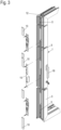
- einen Abschnitt eines Flügelrahmens in einer Explosionsdarstellung
- Figur 4a) - 4d)
- unterschiedliche Faltschiebetüren in einer schematischen Draufsicht.
- In der
Figur 1 sind zwei ein Rahmenteil bildende Verbundprofile 1 dargestellt, die Bestandteil einer mehrflügeligen Tür einer Faltschiebetür sind, wobei die Flügel zu öffnen und zu schließen sind, d.h., die beiden dargestellten Verbundprofile 1 sind relativ zueinander verschiebbar. - Jedes Verbundprofil 1 besteht aus einem ersten Kammerprofil 2 und einem dazu abständig angeordneten zweiten Kammerprofil 3, die durch Abstandsstege 4 miteinander verbunden sind, wobei die Kammerprofile 2, 3 aus einem Leichtmetall und die Abstandsstege 4 aus einem formstabilen Kunststoff bestehen.
- Gemäß der Erfindung sind die sich gegenüberliegenden Verbundprofile 1 auf ihren einander zugewandten Seiten zumindest bereichsweise durch im Querschnitt identische Verschlussprofile 5 verschlossen, die bevorzugt ebenfalls aus Kunststoff bestehen und die sowohl mit den Kammerprofilen 2, 3 wie auch mit dem zugewandten Abstandssteg 4 form- und/oder reibschlüssig verbunden sind, vorzugsweise durch Verrasten.
- Hierzu weist das jeweilige Verschlussprofil 5 sowohl Zungen 6 auf, die in entsprechende geformte Aufnahmen der Kammerprofile 2, 3 eingesetzt sind, wie auch Klammern 7, die einen Fortsatz des benachbarten Abstandssteges 4 übergreifen.
- Durch eine entsprechende Konfiguration der Kammerprofile 2, 3 und des Verschlussprofils 5 ist eine Aufnahmenut 8 geschaffen, in der Türdichtungen 9 (Figur 2) gehalten sind.
- Der dem Verschlussprofil 5 zugewandte Abstandssteg 4 begrenzt ebenso wie das Verschlussprofil 5 einen Raum 17 zur Unterbringung von Beschlagteilen, beispielsweise eines Treibriegels 12, wie er in der
Figur 2 erkennbar ist, und/oder eines Riegelfallenschlosses. - Diese Abbildung zeigt die Anordnung der Verbundprofile 1 nach der
Figur 1 in geschlossener Stellung der Flügel mit in einen Gangflügel eingebautem Kastenschloss, dessen Schließzunge 14 in ein Schließblech des benachbarten Standflügels ragt, wobei das Kastenschloss über einen Griff 11 betätigbar ist.. - Auf den den Verschlussprofilen 5 abgewandten Seiten der Verbundprofile 1 ist jeweils eine Glasscheibe 13 gehalten, wobei die in der Zeichenebene untere Seite der Verbundprofile 1 eine Raumseite bildet, wenn die Tür montiert ist.
- Weiter ist zu erkennen, dass die Verschlussprofile 5 auf ihren einander zugewandten Seiten jeweils mit einer Abdeckleiste 10 überdeckt sind, die mit dem Verschlussprofil 5 verbunden ist, beispielsweise ebenfalls durch Verrasten.
- In den
Figuren 1 und2 ist weiter zu erkennen, dass jedes erste Kammerprofil 2 in Verschieberichtung des jeweiligen Flügels gesehen kürzer ist als das gegenüberliegende zweite Kammerprofil 3, so dass sich in Richtung des anderen Verbundprofils 1 ein Überstand ergibt, wodurch ein Falz gebildet wird. - Die Verschlussprofile 5 sind im Querschnitt identisch ausgebildet, ebenso wie die Verbundprofile 1, von denen eines im Querschnitt um eine gedachte horizontale und vertikale Achse gegenüber dem anderen Verbundprofil 1 gespiegelt ist.
- In der
Figur 3 ist ein Abschnitt eines Standflügels abgebildet, mit sichtbarem zweitem Kammerprofil 3 und eingesetzten Verschlussprofilen 5 sowie in Explosionsabbildung Abdeckleisten 10. Eine Arretierlösung des Standflügels erfolgt mittels eines Handgriffs 16. Ein Stulp 15 mit einer Aufnahmekammer für die Schließzunge 14 ist zwischen zwei Verschlussprofilen 5 angeordnet, ebenso wie weitere ober- und unterhalb dazu vorgesehene Schließmittel für eine Mehrfachverriegelung. - In der
Figur 4 sind mit einer unterschiedlichen Anzahl von Flügeln versehene Faltschiebetüren schematisch abgebildet, jeweils mit einem Gangflügel an den ein Griff 11 angeschlossen ist. Dabei ist in derFigur 4a ) eine Ausführungsvariante mit insgesamt sechs Flügeln gezeigt, deren Gang- und der diesem zugeordnete Standflügel mittig positioniert sind, während in derFigur 4b ) vier Flügel vorgesehen sind mit Gang- und Standflügel rechtsseitig. - Die
Figur 4c ) zeigt eine Ausführung mit insgesamt acht Flügeln, von denen von einer Seite her gesehen der dritte als Stand- und der vierte als Gangflügel ausgebildet sind, während dieFigur 4d ) eine spiegelbildliche Anordnung wiedergibt. -
- 1
- Verbundprofil
- 2
- Kammerprofil
- 3
- Kammerprofil
- 4
- Abstandsstege
- 5
- Verschlussprofil
- 6
- Zunge
- 7
- Klammer
- 8
- Aufnahmenut
- 9
- Türdichtung
- 10
- Abdeckleiste
- 11
- Griff
- 12
- Treibriegel
- 13
- Glasscheibe
- 14
- Schließzunge
- 15
- Stulp
- 16
- Handgriff
- 17
- Raum
Claims (12)
- Mehrflügelige Tür einer Faltschiebetür, bei der jeder Flügel einen Rahmen aufweist, der aus Verbundprofilen (1) besteht, mit jeweils einem ersten Kammerprofil (2) und abständig dazu einem zweiten Kammerprofil (3), die durch Abstandsstege (4) miteinander verbunden sind, gekennzeichnet durch folgende Merkmale:- die sich gegenüberliegenden Verbundprofile (1) zweier, zum Öffnen und Schließen relativ zueinander verschiebbarer Flügel sind auf ihren einander zugewandten Seiten zumindest bereichsweise durch im Querschnitt identische Verschlussprofile (5) verschlossen,- die Kammerprofile (2, 3) jedes dieser sich gegenüberliegenden Verbundprofile (1) sind, in Schieberichtung des jeweiligen Flügels gesehen, in ihrem Querschnittsabmaß unterschiedlich, unter Ausbildung eines Überstands auf der dem jeweils anderen Verbundprofil (1) zugewandten Seite.
- Mehrflügelige Tür nach Anspruch 1, dadurch gekennzeichnet, dass das eine der sich gegenüberliegenden Verbundprofile (1) im Querschnitt um eine gedachte horizontale und vertikale Achse gegenüber dem anderen Verbundprofil (1) gespiegelt ist.
- Mehrflügelige Tür nach Anspruch 1 oder 2, dadurch gekennzeichnet, dass die Verbundprofile (1) im Querschnitt identisch sind.
- Mehrflügelige Tür nach einem der vorhergehenden Ansprüche, dadurch gekennzeichnet, dass das Verschlussprofil (5) mit den jeweiligen Kammerprofilen (2, 3) verbunden ist.
- Mehrflügelige Tür nach einem der vorhergehenden Ansprüche, dadurch gekennzeichnet, dass das Verschlussprofil (5) des einen Verbundprofils (1) auf seiner dem gegenüberliegenden Verschlussprofil (5) zugewandten Seite durch eine Abdeckleiste (10) überdeckt ist.
- Mehrflügelige Tür nach einem der vorhergehenden Ansprüche, dadurch gekennzeichnet, dass das Verschlussprofil (5) mit dem zugewandten Abstandssteg (4) und/oder den Kammerprofilen (2, 3) form- und/oder reibschlüssig verbunden ist.
- Mehrflügelige Tür nach einem der vorhergehenden Ansprüche, dadurch gekennzeichnet, dass der dem Verschlussprofil (5) zugewandte Abstandssteg (4) und das Verschlussprofil (5) miteinander korrespondierende Rastmittel aufweist.
- Mehrflügelige Tür nach einem der vorhergehenden Ansprüche, dadurch gekennzeichnet, dass das Verschlussprofil (5) Zungen (6) aufweist, die in Nuten der Kammerprofile (2, 3) eingreifen.
- Mehrflügelige Tür nach einem der vorhergehenden Ansprüche, dadurch gekennzeichnet, dass das Verschlussprofil (5) und der diesem zugewandte Abstandssteg (4) einen Raum (17) begrenzen.
- Mehrflügelige Tür nach einem der vorhergehenden Ansprüche, dadurch gekennzeichnet, dass das Verschlussprofil (5) aus einem formstabilen Kunststoff besteht.
- Mehrflügelige Tür nach einem der vorhergehenden Ansprüche, dadurch Ein gekennzeichnet, dass im Raum (17) ein Treibriegel (12) und/oder ein Riegelstangenfallenschloss positioniert sind.
- Mehrflügelige Tür nach einem der vorhergehenden Ansprüche, dadurch gekennzeichnet, dass in einer Aufnahmenut (8) der Kammerprofile (2,3) eine Türdichtung (9) angeordnet ist.
Applications Claiming Priority (1)
| Application Number | Priority Date | Filing Date | Title |
|---|---|---|---|
| DE202023101846.7U DE202023101846U1 (de) | 2023-04-13 | 2023-04-13 | Mehrflügelige Tür einer Faltschiebetür |
Publications (2)
| Publication Number | Publication Date |
|---|---|
| EP4446553A1 true EP4446553A1 (de) | 2024-10-16 |
| EP4446553B1 EP4446553B1 (de) | 2026-04-15 |
Family
ID=86606079
Family Applications (1)
| Application Number | Title | Priority Date | Filing Date |
|---|---|---|---|
| EP24155245.4A Active EP4446553B1 (de) | 2023-04-13 | 2024-02-01 | Mehrflügelige tür einer faltschiebetür |
Country Status (2)
| Country | Link |
|---|---|
| EP (1) | EP4446553B1 (de) |
| DE (1) | DE202023101846U1 (de) |
Families Citing this family (1)
| Publication number | Priority date | Publication date | Assignee | Title |
|---|---|---|---|---|
| KR102898100B1 (ko) * | 2024-05-27 | 2025-12-09 | 대신알루텍 주식회사 | 폴딩도어의 틈 차단 단열구조 |
Citations (7)
| Publication number | Priority date | Publication date | Assignee | Title |
|---|---|---|---|---|
| EP0277531A1 (de) * | 1987-01-27 | 1988-08-10 | SCHÜCO International GmbH & Co. | Faltschiebetür oder -fenster |
| EP1365097A2 (de) * | 2002-05-24 | 2003-11-26 | Solarlux Aluminium Systeme Gmbh | Faltanlage |
| EP2116685A2 (de) * | 2008-05-08 | 2009-11-11 | Norsk Hydro Asa | Tür, Fenster oder dergleichen in wärmegedämmter Ausführung |
| DE102010012159A1 (de) * | 2010-03-20 | 2011-09-22 | Erhard Schulz | Mehrteiliges Profilrahmensystem für Türen, Tore, Wintergärten und Fenster |
| EP3339541A1 (de) * | 2016-12-23 | 2018-06-27 | Solarlux GmbH | Fixiervorrichtung für insbesondere glasfaltanlagen |
| DE102019124264A1 (de) * | 2019-09-10 | 2021-03-11 | SCHÜCO International KG | Rahmenprofil und Verfahren zur Montage eines biegsamen Bandes umfassend zumindest eine Isolierbaustofflage in ein Rahmenprofil |
| EP3034733B1 (de) * | 2014-12-17 | 2022-06-01 | dormakaba Deutschland GmbH | Faltflügeltüranlage |
-
2023
- 2023-04-13 DE DE202023101846.7U patent/DE202023101846U1/de active Active
-
2024
- 2024-02-01 EP EP24155245.4A patent/EP4446553B1/de active Active
Patent Citations (7)
| Publication number | Priority date | Publication date | Assignee | Title |
|---|---|---|---|---|
| EP0277531A1 (de) * | 1987-01-27 | 1988-08-10 | SCHÜCO International GmbH & Co. | Faltschiebetür oder -fenster |
| EP1365097A2 (de) * | 2002-05-24 | 2003-11-26 | Solarlux Aluminium Systeme Gmbh | Faltanlage |
| EP2116685A2 (de) * | 2008-05-08 | 2009-11-11 | Norsk Hydro Asa | Tür, Fenster oder dergleichen in wärmegedämmter Ausführung |
| DE102010012159A1 (de) * | 2010-03-20 | 2011-09-22 | Erhard Schulz | Mehrteiliges Profilrahmensystem für Türen, Tore, Wintergärten und Fenster |
| EP3034733B1 (de) * | 2014-12-17 | 2022-06-01 | dormakaba Deutschland GmbH | Faltflügeltüranlage |
| EP3339541A1 (de) * | 2016-12-23 | 2018-06-27 | Solarlux GmbH | Fixiervorrichtung für insbesondere glasfaltanlagen |
| DE102019124264A1 (de) * | 2019-09-10 | 2021-03-11 | SCHÜCO International KG | Rahmenprofil und Verfahren zur Montage eines biegsamen Bandes umfassend zumindest eine Isolierbaustofflage in ein Rahmenprofil |
Also Published As
| Publication number | Publication date |
|---|---|
| EP4446553B1 (de) | 2026-04-15 |
| DE202023101846U1 (de) | 2023-06-22 |
Similar Documents
| Publication | Publication Date | Title |
|---|---|---|
| EP0666396B1 (de) | Sicherheitstür und Sicherheitsvorrichtung zum Einbau in eine Tür | |
| EP0945582A2 (de) | Fenster oder Tür | |
| EP3339551A1 (de) | Isolierkörper für mehrschalige bauelemente | |
| EP4446553B1 (de) | Mehrflügelige tür einer faltschiebetür | |
| EP4299870B1 (de) | Blendrahmen für eine tür mit extrusionsrahmen und schwelle, tür mit einem derartigen blendrahmen und verfahren zur herstellung dieser tür | |
| DE102009051070A1 (de) | Wandsystem | |
| EP2252751B1 (de) | Treibstangenbeschlag für fenster oder tür | |
| EP4223965B1 (de) | Adapterbeschlag für ein fenster oder eine tür zur realisierung einer sparlüftungsfunktion | |
| EP0989277A2 (de) | Tür, insbesondere Brandschutztür | |
| EP2369115A2 (de) | Aushebesicherung für Schiebefenster oder Schiebetüren | |
| EP2072744B1 (de) | Zargenprofil für eine Hebe-Schiebetür | |
| DE102023110081A1 (de) | Schiebetür mit schmaler Mittelpartie | |
| EP0845566A2 (de) | Flügeleinheit | |
| EP1580374B1 (de) | Fenster oder Tür | |
| EP4174273A2 (de) | Profilsystem für eine schiebetür- oder schiebefensteranordnung, insbesondere dachschiebetür oder dachschiebefenster | |
| EP3626927B1 (de) | Verbundprofil für fenster und/oder türen | |
| EP2857624B1 (de) | Gebäudeabschluss in einbruchhemmender und/oder durchschusshemmender Ausführung | |
| EP0571803B1 (de) | Kupplungsvorrichtung für aneinanderstossende Stulpschienenabschnitte | |
| DE10251431A1 (de) | Haustür | |
| DE19603415C1 (de) | Vorrichtung zur Verriegelung eines zwischen zwei Endstellungen um eine Achse schwenkbaren, in Verschlußstellung befindlichen Bauteils zum Verschließen einer Zugangsöffnung zu einem von Wänden umschlossenen Raum | |
| EP3656955B1 (de) | Schliessteil | |
| EP2270297B1 (de) | Sprengwirkungshemmender und/oder einbruchhemmender Gebäudeabschluss | |
| EP1659241B1 (de) | Beschlag zur Einbruchsicherung für ein mehrflügeliges Fenster oder Tür | |
| DE10108697C2 (de) | Flügeleinrichtung mit Gelenkeinrichtung in einem Randprofil des Flügels | |
| DE102023202379A1 (de) | Eckfenster oder Ecktür mit abstellbaren und parallel zum festen Rahmen verschiebbaren Schiebeflügeln |
Legal Events
| Date | Code | Title | Description |
|---|---|---|---|
| PUAI | Public reference made under article 153(3) epc to a published international application that has entered the european phase |
Free format text: ORIGINAL CODE: 0009012 |
|
| STAA | Information on the status of an ep patent application or granted ep patent |
Free format text: STATUS: THE APPLICATION HAS BEEN PUBLISHED |
|
| AK | Designated contracting states |
Kind code of ref document: A1 Designated state(s): AL AT BE BG CH CY CZ DE DK EE ES FI FR GB GR HR HU IE IS IT LI LT LU LV MC ME MK MT NL NO PL PT RO RS SE SI SK SM TR |
|
| STAA | Information on the status of an ep patent application or granted ep patent |
Free format text: STATUS: REQUEST FOR EXAMINATION WAS MADE |
|
| 17P | Request for examination filed |
Effective date: 20241126 |
|
| RBV | Designated contracting states (corrected) |
Designated state(s): AL AT BE BG CH CY CZ DE DK EE ES FI FR GB GR HR HU IE IS IT LI LT LU LV MC ME MK MT NL NO PL PT RO RS SE SI SK SM TR |
|
| STAA | Information on the status of an ep patent application or granted ep patent |
Free format text: STATUS: EXAMINATION IS IN PROGRESS |
|
| 17Q | First examination report despatched |
Effective date: 20250723 |
|
| GRAP | Despatch of communication of intention to grant a patent |
Free format text: ORIGINAL CODE: EPIDOSNIGR1 |
|
| STAA | Information on the status of an ep patent application or granted ep patent |
Free format text: STATUS: GRANT OF PATENT IS INTENDED |
|
| INTG | Intention to grant announced |
Effective date: 20251204 |
|
| GRAS | Grant fee paid |
Free format text: ORIGINAL CODE: EPIDOSNIGR3 |
|
| GRAA | (expected) grant |
Free format text: ORIGINAL CODE: 0009210 |
|
| STAA | Information on the status of an ep patent application or granted ep patent |
Free format text: STATUS: THE PATENT HAS BEEN GRANTED |
|
| AK | Designated contracting states |
Kind code of ref document: B1 Designated state(s): AL AT BE BG CH CY CZ DE DK EE ES FI FR GB GR HR HU IE IS IT LI LT LU LV MC ME MK MT NL NO PL PT RO RS SE SI SK SM TR |
|
| P01 | Opt-out of the competence of the unified patent court (upc) registered |
Free format text: CASE NUMBER: UPC_APP_0009599_4446553/2026 Effective date: 20260311 |
|
| REG | Reference to a national code |
Ref country code: CH Ref legal event code: F10 Free format text: ST27 STATUS EVENT CODE: U-0-0-F10-F00 (AS PROVIDED BY THE NATIONAL OFFICE) Effective date: 20260415 |
|
| REG | Reference to a national code |
Ref country code: CH Ref legal event code: R17 Free format text: ST27 STATUS EVENT CODE: U-0-0-R10-R17 (AS PROVIDED BY THE NATIONAL OFFICE) Effective date: 20260429 |
|
| REG | Reference to a national code |
Ref country code: DE Ref legal event code: R096 Ref document number: 502024001031 Country of ref document: DE |