EP4434902A1 - Dispositif et procédé d'emballage de plantes potées avec une enveloppe - Google Patents
Dispositif et procédé d'emballage de plantes potées avec une enveloppe Download PDFInfo
- Publication number
- EP4434902A1 EP4434902A1 EP24153903.0A EP24153903A EP4434902A1 EP 4434902 A1 EP4434902 A1 EP 4434902A1 EP 24153903 A EP24153903 A EP 24153903A EP 4434902 A1 EP4434902 A1 EP 4434902A1
- Authority
- EP
- European Patent Office
- Prior art keywords
- potted plant
- packaging station
- cover
- supply
- fall
- Prior art date
- Legal status (The legal status is an assumption and is not a legal conclusion. Google has not performed a legal analysis and makes no representation as to the accuracy of the status listed.)
- Pending
Links
- 238000004806 packaging method and process Methods 0.000 title claims abstract description 73
- 238000000034 method Methods 0.000 title claims abstract description 16
- 230000005484 gravity Effects 0.000 claims abstract description 16
- 238000003780 insertion Methods 0.000 claims abstract description 16
- 230000037431 insertion Effects 0.000 claims abstract description 16
- 230000001960 triggered effect Effects 0.000 claims description 18
- 238000006073 displacement reaction Methods 0.000 claims description 9
- 230000003313 weakening effect Effects 0.000 claims description 4
- 230000003247 decreasing effect Effects 0.000 claims 1
- 238000005259 measurement Methods 0.000 claims 1
- 238000010276 construction Methods 0.000 description 3
- 230000000694 effects Effects 0.000 description 3
- 238000013016 damping Methods 0.000 description 2
- 230000007423 decrease Effects 0.000 description 2
- 230000001154 acute effect Effects 0.000 description 1
- 239000000853 adhesive Substances 0.000 description 1
- 238000004026 adhesive bonding Methods 0.000 description 1
- 230000001070 adhesive effect Effects 0.000 description 1
- 230000004888 barrier function Effects 0.000 description 1
- 230000015572 biosynthetic process Effects 0.000 description 1
- 230000000903 blocking effect Effects 0.000 description 1
- 239000011248 coating agent Substances 0.000 description 1
- 238000000576 coating method Methods 0.000 description 1
- 238000010413 gardening Methods 0.000 description 1
- 230000003287 optical effect Effects 0.000 description 1
- 239000004033 plastic Substances 0.000 description 1
- 239000002985 plastic film Substances 0.000 description 1
- 229920006255 plastic film Polymers 0.000 description 1
- 230000007704 transition Effects 0.000 description 1
Images

Classifications
-
- B—PERFORMING OPERATIONS; TRANSPORTING
- B65—CONVEYING; PACKING; STORING; HANDLING THIN OR FILAMENTARY MATERIAL
- B65B—MACHINES, APPARATUS OR DEVICES FOR, OR METHODS OF, PACKAGING ARTICLES OR MATERIALS; UNPACKING
- B65B25/00—Packaging other articles presenting special problems
- B65B25/02—Packaging agricultural or horticultural products
-
- B—PERFORMING OPERATIONS; TRANSPORTING
- B65—CONVEYING; PACKING; STORING; HANDLING THIN OR FILAMENTARY MATERIAL
- B65B—MACHINES, APPARATUS OR DEVICES FOR, OR METHODS OF, PACKAGING ARTICLES OR MATERIALS; UNPACKING
- B65B25/00—Packaging other articles presenting special problems
- B65B25/02—Packaging agricultural or horticultural products
- B65B25/023—Packaging flower bouquets
-
- B—PERFORMING OPERATIONS; TRANSPORTING
- B65—CONVEYING; PACKING; STORING; HANDLING THIN OR FILAMENTARY MATERIAL
- B65B—MACHINES, APPARATUS OR DEVICES FOR, OR METHODS OF, PACKAGING ARTICLES OR MATERIALS; UNPACKING
- B65B25/00—Packaging other articles presenting special problems
- B65B25/02—Packaging agricultural or horticultural products
- B65B25/026—Packaging flower pots
-
- B—PERFORMING OPERATIONS; TRANSPORTING
- B65—CONVEYING; PACKING; STORING; HANDLING THIN OR FILAMENTARY MATERIAL
- B65B—MACHINES, APPARATUS OR DEVICES FOR, OR METHODS OF, PACKAGING ARTICLES OR MATERIALS; UNPACKING
- B65B43/00—Forming, feeding, opening or setting-up containers or receptacles in association with packaging
- B65B43/12—Feeding flexible bags or carton blanks in flat or collapsed state; Feeding flat bags connected to form a series or chain
- B65B43/14—Feeding individual bags or carton blanks from piles or magazines
- B65B43/16—Feeding individual bags or carton blanks from piles or magazines by grippers
- B65B43/18—Feeding individual bags or carton blanks from piles or magazines by grippers by suction-operated grippers
Definitions
- the invention relates to a device for packaging potted plants with a cover, in particular with a cone-shaped cover, preferably made of paper, comprising a feed device with which potted plants can be guided to a packaging station or at which potted plants can be guided to a packaging station, and further comprising a packaging station in which a potted plant can be packaged with a cover, wherein the packaging station has a holding device for a supply of covers and at least one movable vacuum gripper with which a frontmost flat cover of a supply of covers held in the holding device can be unfolded to form an upper insertion opening, and which further comprises a removal device at which a packaged potted plant can be removed from the packaging station or with which a packaged potted plant can be removed from the packaging station.
- the invention also relates to a method for packaging potted plants with a cover, in particular with a cone-shaped cover, preferably made of paper, in which a potted plant is fed to a packaging station with or on a feed device and in the packaging station, the potted plant is packaged in a cover, wherein a supply of covers is kept ready in a holding device and with at least one movable vacuum gripper the frontmost flat cover of the supply of covers held in the holding device is unfolded to form an upper insertion opening in the cover, and the packaged potted plant is guided out of the packaging station on or with a removal device.
- Such a supply is preferably formed from a stack of envelopes lying flat on top of one another, e.g. folded or glued together from two sheets, in particular flat sheets, which in the flat state have a front and a rear envelope wall, in particular which touch each other in this state, wherein all rear envelope walls of all envelopes in the supply are detachably connected to one another, in particular at a weakening line/perforation.
- each rear casing wall particularly at the upper, wider opening of the two opposite openings of the casing, can have a tab that protrudes over the front casing wall, with the respective tab being detachably connected to the rear casing wall at a weakening line and all tabs of all casings being connected to one another, e.g. by gluing or some other type of blocking.
- the gripped front casing wall is removed from the held rear casing wall and the casing is unfolded, resulting in a continuous casing with a larger upper opening and a smaller lower opening.
- the supply of flat-lying casings can be held in the holding device such that, at least after unfolding the casing, the larger opening of each casing faces upwards and the smaller opening faces downwards.
- the flat-lying casings are at least substantially all parallel to a vertical plane.
- unfolding means preparing a flat-lying cover to receive a pot of the potted plant by forming and/or widening the respective openings from the flat-lying state.
- a device and a method of the type mentioned above is known, for example, from the publication EP 1 600 381 A1 According to the teaching mentioned therein, a potted plant to be packaged with a cover is held in a packaging unit with a holding device that engages around the outside of the pot, and an unfolded/opened cover is guided around the holding device and the pot with an upward movement in which the cover tears away from the supply, after which the holding device releases the packaged potted plant.
- Such a construction is complex, as a device is required to move the unfolded cover upwards, and is also prone to errors, particularly when covers made exclusively of paper are used.
- Such covers are significantly stiffer when lying flat on top of one another, e.g. folded, than, for example, plastic film covers, and when unfolded with a vacuum gripper that engages near the upper edge, they tend to form a fold in the front cover wall, which runs essentially perpendicular to the direction of connection between the upper and lower openings and which prevents the cover from being opened completely over its entire height.
- the packaging station is arranged in the direction of gravity between the feed device and the removal device and comprises a fall path that can be traversed by the potted plant in the fall due to gravity, and the at least one vacuum gripper and the holding device are arranged, in particular on opposite sides, around the fall path.
- the packaging station is arranged in the direction of gravity between the feed device and the removal device and the packaging station comprises a fall path which is traversed by the potted plant in the fall caused by gravity, wherein the potted plant enters the unfolded insertion opening of the cover and the unfolded cover is released from the supply by the kinetic energy of the falling potted plant and the packaged potted plant falls into the removal device.
- the packaging station with its drop section is thus actually arranged between the feeding device and the removal device.
- the design according to the invention preferably ensures that the front casing wall can be pulled transversely through the drop section with the at least one vacuum gripper, so that after the insertion opening has been unfolded, the drop section leads through the insertion opening and through the unfolded casing, i.e. at least through the upper opening, in particular also through its two openings.
- the potted plant is thus packaged according to the invention as it falls from the feeding device to the removal device.
- the type of construction of the feed device is irrelevant for the invention. What is important is that the potted plants are fed to the packaging station or at least in the direction of the packaging station with or on it.
- the feeding device ends where the packaging station begins. There can be a spatial overlap between the feeding device and the packaging station.
- the feeding device can preferably carry out an active feeding of potted plants to the packaging station, e.g. by transporting the potted plant with or in the feeding device, e.g. this can be achieved by a conveyor belt or by a rotating star or by a chute or similar. It can be provided that the potted plants are transported e.g. by operating personnel or also automatically, e.g. by a robotic arm, from a supply of potted plants onto such a feeding device for further transport towards the packaging station, preferably into it.
- the feeding device itself may not be an active device, i.e. it may be designed as a storage platform or a storage rack, so that with this type of feeding device it does not actively transport the potted plant itself, but merely structurally defines the location where the potted plant is to be placed, e.g. by staff or automatically, in order to be fed to the packaging station.
- the feeding device thus defines, for example, an entrance area of the packaging station, so that the potted plant is or will be fed to the packaging station by being placed there manually or automatically.
- the removal device begins where the packaging station ends. There may be a spatial overlap between the packaging station and the removal device.
- the removal device can preferably carry out an active removal of packaged potted plants from the packaging station, e.g. by transporting the packaged potted plants away from the packaging station with or in the removal device, e.g. this can be achieved by a conveyor belt or by a rotating star or by a slide or similar. It can be provided that the potted plants are removed from the removal device, e.g. by operating personnel or also automatically, e.g. by a robot arm, and are placed in a supply of packaged potted plants.
- the removal device itself may not be an active device, i.e. it may be designed as a storage platform or a storage rack in which the packaged, potted plant falling out of the packaging station is caught, so that with this type of removal device, it does not actively transport the packaged, potted plant itself, but merely structurally defines the location from where the packaged, potted plant is to be removed, e.g. by personnel or automatically.
- the removal device thus defines, for example, an exit area of the packaging station, so that the packaged, potted plant can be removed from the packaging station with or on the removal device, or is removed by being removed from there manually or automatically.
- the invention preferably provides that the fall height between the beginning of the fall path, which preferably corresponds to the entrance of the packaging station, in particular a transition area between the feed device and the packaging station, and the holding device of the casing supply can be adjusted.
- This allows the kinetic energy of the potted plant obtained by falling to the holding device to be adjusted, e.g. the fall height can be set higher for lighter potted plants than for heavier ones in order to reliably maintain the energy required to tear off the casing from the supply.
- a preferred development of all possible embodiments of the invention provides that a guide device is arranged in the fall section above the holding device, wherein at least one wall region of the guide device is not aligned parallel to the direction of gravity, in particular the distance of the at least one wall region to a vertical fall axis, around which the fall section is formed, decreases in the direction of fall.
- the packaging station has a triggering device at the beginning of its fall path, with which the fall of a potted plant fed into the triggering device or at least feedable can be triggered, in particular can be triggered in a triggered manner depending on a control signal.
- Such a control signal can be triggered, for example, by a displacement sensor of an actuator that moves the at least one vacuum gripper.
- a displacement sensor of the actuator of the at least one vacuum gripper can be used to determine that the insertion opening of the cover is open wide enough because the vacuum gripper has covered a sufficiently large distance during its opening movement to unfold the folded cover.
- the entry of a potted plant into the fall path is therefore preferably only triggered in response to a control signal which signals the sufficiently wide opening of the insertion opening of a cover.
- the successful or at least sufficiently wide unfolding of the cover can also be detected by means of an optical sensor, e.g. a light barrier, which is passed through by the front cover wall during the opening process.
- an optical sensor e.g. a light barrier
- the triggering device has a trapdoor onto which a potted plant can be placed with the feed device or in the feed device.
- This trapdoor can, for example, only be unlocked and release the potted plant for gravity-induced fall when the control signal triggers the triggering device for this purpose, eg by moving an unlocking element of the trapdoor to open the trapdoor.
- Such a trap door can preferably have at least one recess, e.g. to achieve a weight saving or also have a friction-reducing coating, e.g. to ensure that a potted plant can be transferred from the feed device to the trap door.
- the invention can further provide in every possible embodiment that the packaging station has at least two vacuum grippers arranged one below the other, in which the effective vacuum can be switched off at different times.
- the effect of the vacuum can be set up in such a way that the vacuum of the lower vacuum gripper of at least two vacuum grippers arranged one below the other can be switched off before the vacuum of the upper vacuum gripper during an opening movement.
- a casing can thus be unfolded with two vacuum grippers arranged one below the other, whereby starting from a starting time of the opening movement, the effective vacuum on the lower vacuum gripper is switched off before the vacuum on the upper vacuum gripper.
- the switching on of the effect of the negative pressure on the at least two grippers can thus preferably take place simultaneously for the purpose of gripping the front shell wall simultaneously.
- the casing can be gripped and pulled in two zones lying one below the other, but due to the conicity of the casing, the distance that can be pulled is shorter for the lower gripper, so that it has to switch off earlier, after which the upper gripper continues to pull.
- At least two grippers arranged vertically one below the other can be supplied by the same vacuum source, but have separate and preferably independently controllable shut-off valves to switch off the effect of the vacuum on the gripper.
- the switch-off can take place depending on a signal from a displacement sensor that detects the range of movement of the actuator that moves the grippers, preferably both at the same time.
- an upper gripper is arranged to grip a casing in its upper half and a lower gripper is arranged to grip the casing in its lower half.
- the lower gripper is positioned below a crease line that would be created if only the upper gripper pulled on the front casing wall.
- the invention can provide that the packaging device, in particular on the holding device, has at least one compressed air nozzle with which compressed air, in particular a time-limited compressed air blast, can be emitted in the direction of the insertion opening.
- the emission of compressed air from the at least one compressed air nozzle can be triggered as a function of a control signal, in particular which can be triggered by a displacement sensor of an actuator which moves the at least one vacuum gripper.
- the emission of compressed air is triggered before a maximum path in the opening movement of the at least one vacuum gripper is exceeded, in particular in order to avoid the generation of a horizontal kink in the casing, which would prevent complete opening.
- compressed air in particular a time-limited compressed air blast, is injected into the partially opened shell, in particular in order to open it completely.
- the at least one or, for example, also one of at least two compressed air nozzles has an emission direction which points from a position at a distance in front of the holding device in the direction of the holding device, in particular which leads under the weakening line of the connected tabs of a casing supply.
- the at least one compressed air nozzle is arranged laterally offset to the tabs remaining in the supply, preferably two nozzles are arranged on both sides around the tabs of a supply of sleeves, in particular thus also laterally to the holding device.
- a further preferred embodiment can provide that the packaging station has a braking device at the end of its fall path, in particular for reducing the falling speed of a potted plant before entering the removal device.
- Such a braking device can, for example, have at least one wall running obliquely to the direction of gravity, preferably several walls arranged around the potted plant, with which the packaged potted plant, in particular the cover which is supported by the pot, comes into contact when falling.
- a wall can be mounted in a resilient manner.
- a braking device can also generate a preferably pulsed air flow directed against the falling direction of the packaged potted plant in order to brake the plant as it falls.
- a packaged potted plant falls through a braking device which removes kinetic energy from the packaged potted plant so that the packaged potted plant enters the removal device from the braking device at a reduced speed.
- a braking device can also comprise a fall damping element which is arranged under the potted plant, in particular at the end of the fall path, at least during the fall. It can preferably be provided that such a braking device can be or is removed from the fall path after the fallen plant has been dampened, in particular in such a way that the potted plant thereby reaches the removal device or a part of the removal device.
- a fall damping element can be designed, for example, as a spring, e.g. a coil spring or gas pressure spring.
- a further development can also provide that a plurality of holders are present in the device, in particular wherein a supply of flat-lying casings is attached or at least attachable to such a holder, wherein the respective holder is movable, in particular all holders are movable simultaneously with a conveyor device, in particular so that a holder with an exhausted supply can be moved out of the packaging station and - in particular at the same time - a holder with a new supply can be moved into the packaging station.
- all holders can be attached to a common conveyor belt which is guided through the packaging station.
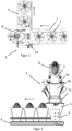
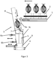
- the figures show a device for packaging which has a conveyor belt as a feed device 1, with which potted plants 2 are conveyed to a packaging station 3. It is irrelevant how the potted plants reach the feed device 1.
- the potted plants are transported to a release device 3a of the packaging station 3, which is designed as a trap door and can be pivoted about a horizontal axis, in particular when the opening of the trap door is triggered, e.g. by a control signal.
- the potted plant 2 standing on it falls into the fall section 3b of the packaging station 3, which adjoins the trapdoor downwards and extends to a removal station 4, which in turn is designed as a conveyor belt in order to transport the potted plants 2 that have fallen into the removal station 4 and are then packaged away from the packaging station 3.
- a holding device 3c is also provided for a supply of flat-lying/flat-hanging sleeves 5, the rear sleeve walls of which are connected to one another in a tearable manner.
- a frontmost cover from the supply is opened by being gripped by a gripper 6a and/or 6b using negative pressure and pulled away from the supply, whereby the cover 5 is unfolded.
- the Figure 3 shows a potted plant in the fall on the way into the unfolded cover 5, which is still attached to the supply with its rear cover wall in the situation shown.
- the casing 5 is carried along by the plant 2 and torn off from the supply, after which the plant 2 is packaged and falls into the removal device 4.
- the packaging station 3 has two vacuum grippers 6a and 6b arranged one below the other.
- only one vacuum gripper 6a can also be provided.
- the vacuum grippers 6a/6b are or the at least one vacuum gripper 6a is movable towards and away from the front casing wall of a casing 5 of the supply, in particular preferably horizontally movable.
- a control signal can be triggered when a limit value is exceeded, which actually indicates that the cover 5 is open enough and can trigger the falling of a plant into the fall path 3b by opening the trap door in response to this control signal.
- the opening of the casing 5 can be supported by at least one compressed air nozzle 7, with which an air flow, in particular a compressed air blast, can be emitted into the partially opened casing.
- the emission of the compressed air blast is preferably also triggered by a control signal that can be provided by the displacement sensor, which detects the range of movement of the at least one vacuum gripper during its opening movement and provides the control signal when a limit value is exceeded.
- the control signal can be the same one that triggers the triggering device and initiates the fall.
- the invention further shows that the falling plant 2 can be safely guided into the opened cover 5 using a guide device 8.
- the guide device 8 preferably comprises a wall inclined to the direction of gravity, preferably inclined at an acute angle, which more preferably extends at least partially around the plant 2 or the fall path 3b.
- the guide device can thus also form a channel.
- a braking device 9 can be provided, which reduces the falling speed of the packaged plant 2 and e.g. formed by at least one wall inclined to the direction of fall.
Landscapes
- Engineering & Computer Science (AREA)
- Mechanical Engineering (AREA)
- Life Sciences & Earth Sciences (AREA)
- Agronomy & Crop Science (AREA)
- Cultivation Receptacles Or Flower-Pots, Or Pots For Seedlings (AREA)
Applications Claiming Priority (1)
| Application Number | Priority Date | Filing Date | Title |
|---|---|---|---|
| DE102023107219.6A DE102023107219A1 (de) | 2023-03-22 | 2023-03-22 | Vorrichtung und Verfahren zum Verpacken getopfter Planzen mit einer Hülle |
Publications (1)
| Publication Number | Publication Date |
|---|---|
| EP4434902A1 true EP4434902A1 (fr) | 2024-09-25 |
Family
ID=89723167
Family Applications (1)
| Application Number | Title | Priority Date | Filing Date |
|---|---|---|---|
| EP24153903.0A Pending EP4434902A1 (fr) | 2023-03-22 | 2024-01-25 | Dispositif et procédé d'emballage de plantes potées avec une enveloppe |
Country Status (2)
| Country | Link |
|---|---|
| EP (1) | EP4434902A1 (fr) |
| DE (1) | DE102023107219A1 (fr) |
Citations (6)
| Publication number | Priority date | Publication date | Assignee | Title |
|---|---|---|---|---|
| US5921060A (en) * | 1996-05-07 | 1999-07-13 | Southpac Trust International, Inc. | Apparatus for covering and banding a pot |
| EP1254837A1 (fr) * | 2001-05-02 | 2002-11-06 | Michael John Smith | Dispositif pour l'introduction des bouquets dans des enveloppes |
| EP1266831A2 (fr) * | 2001-06-13 | 2002-12-18 | De Vries Engineering B.V. | Procédé et dispositif d'emballage d'un bouquet de fleurs |
| US6691495B2 (en) * | 1992-09-30 | 2004-02-17 | Southpac Trust International, Inc. | Method for packaging a potted plant |
| EP1600381A1 (fr) | 2004-05-28 | 2005-11-30 | Terra International B.V. | Dispositif et procédé pour recouvrir une plante en pot avec un manchon |
| NL1031378C2 (nl) * | 2006-03-15 | 2007-09-18 | Edward Keijzer | Werkwijze en inrichting voor het aanbrengen van een hoes om een potplant. |
-
2023
- 2023-03-22 DE DE102023107219.6A patent/DE102023107219A1/de active Pending
-
2024
- 2024-01-25 EP EP24153903.0A patent/EP4434902A1/fr active Pending
Patent Citations (6)
| Publication number | Priority date | Publication date | Assignee | Title |
|---|---|---|---|---|
| US6691495B2 (en) * | 1992-09-30 | 2004-02-17 | Southpac Trust International, Inc. | Method for packaging a potted plant |
| US5921060A (en) * | 1996-05-07 | 1999-07-13 | Southpac Trust International, Inc. | Apparatus for covering and banding a pot |
| EP1254837A1 (fr) * | 2001-05-02 | 2002-11-06 | Michael John Smith | Dispositif pour l'introduction des bouquets dans des enveloppes |
| EP1266831A2 (fr) * | 2001-06-13 | 2002-12-18 | De Vries Engineering B.V. | Procédé et dispositif d'emballage d'un bouquet de fleurs |
| EP1600381A1 (fr) | 2004-05-28 | 2005-11-30 | Terra International B.V. | Dispositif et procédé pour recouvrir une plante en pot avec un manchon |
| NL1031378C2 (nl) * | 2006-03-15 | 2007-09-18 | Edward Keijzer | Werkwijze en inrichting voor het aanbrengen van een hoes om een potplant. |
Also Published As
| Publication number | Publication date |
|---|---|
| DE102023107219A1 (de) | 2024-09-26 |
Similar Documents
| Publication | Publication Date | Title |
|---|---|---|
| EP0234228B1 (fr) | Dispositif pour l'individualisation et l'érection de boîtes pliées | |
| EP2250093B1 (fr) | Procédé et dispositif pour introduire des sachets (tubulaires) dans des cartons | |
| DD213890A5 (de) | Verfahren und vorrichtung zum herstellen von sammelpackungen | |
| DE102007053854A1 (de) | Verfahren und Vorrichtung zum Füllen und Verschließen von Tabakbeuteln | |
| DE1511506A1 (de) | Karton-Zufuehr- und Aufrichtvorrichtung | |
| EP3549879B1 (fr) | Dispositif d'emballage pour articles et procédé de fourniture des découpages d'emballage plans pour articles | |
| DE2917758A1 (de) | Vorrichtung zum auffalten flach gefalteter, schlauchfoermiger kartonabschnitte bzw. kartonrohlinge | |
| CH677100A5 (fr) | ||
| DE2614064B2 (de) | Vorrichtung zum öffnen von Kartons | |
| DE19808881A1 (de) | Verfahren und Vorrichtung zum Herstellen von Packungen mit verleimten Faltlappen | |
| EP4434902A1 (fr) | Dispositif et procédé d'emballage de plantes potées avec une enveloppe | |
| EP0992433A2 (fr) | Procédé et dispositif de transport, de vérification, de remplissage et de fermeture de sacs | |
| DE102009046349A1 (de) | Ausschleusstation für Kartonzuschnitte und Verfahren zum Herstellen und Ausschleusen von Kartonzuschnitten | |
| WO2012110171A2 (fr) | Poste de remplissage et procédé de remplissage d'une enveloppe | |
| DE19700236C1 (de) | Vorrichtung zum Überführen von Kartonzuschnitten für Klappschachteln | |
| DE102018105899B4 (de) | Vorrichtung zum Bewegen eines Polstermittels in einen Transportbehälter, sowie Verfahren zum Betreiben einer solchen Vorrichtung | |
| DE102020114298A1 (de) | Verpackungsvorrichtung und Verfahren zur Herstellung einer Verpackungseinheit | |
| EP1149791A2 (fr) | Dispositif pour prélever une feuille d'essai dans un appareil de sortie d'une machine à imprimer des feuilles | |
| EP4408752A1 (fr) | Procédé et dispositif pour acheminer un groupe de produits de l'industrie du tabac, en tant que contenu d'emballage, jusqu'à une pièce découpée pour un emballage pour des produits de l'industrie du tabac | |
| EP3558828B1 (fr) | Dispositif et procédé d'enfilement destinés à enfiler des sacs à soupape | |
| DE4209151C2 (de) | Vorrichtung zur Bearbeitung von faltbaren Verpackungszuschnitten, insbesondere zur Herstellung von Flaschenkartons | |
| EP2048085B1 (fr) | Dispositif et procédé d'emballage d'objets plats transportés dans un courant de refoulement | |
| DE19736388A1 (de) | Verfahren und Vorrichtung zum Transportieren von Banderolen oder dergleichen | |
| CH709346A1 (de) | Verfahren zum automatischen Öffnen einer Tragetasche sowie Vorrichtung zur Durchführung des Verfahrens. | |
| EP0916579A1 (fr) | Dispositif pour ouvrir des sacs en matière plastique |
Legal Events
| Date | Code | Title | Description |
|---|---|---|---|
| PUAI | Public reference made under article 153(3) epc to a published international application that has entered the european phase |
Free format text: ORIGINAL CODE: 0009012 |
|
| STAA | Information on the status of an ep patent application or granted ep patent |
Free format text: STATUS: THE APPLICATION HAS BEEN PUBLISHED |
|
| AK | Designated contracting states |
Kind code of ref document: A1 Designated state(s): AL AT BE BG CH CY CZ DE DK EE ES FI FR GB GR HR HU IE IS IT LI LT LU LV MC ME MK MT NL NO PL PT RO RS SE SI SK SM TR |
|
| STAA | Information on the status of an ep patent application or granted ep patent |
Free format text: STATUS: REQUEST FOR EXAMINATION WAS MADE |
|
| 17P | Request for examination filed |
Effective date: 20250321 |