EP0916579A1 - Dispositif pour ouvrir des sacs en matière plastique - Google Patents
Dispositif pour ouvrir des sacs en matière plastique Download PDFInfo
- Publication number
- EP0916579A1 EP0916579A1 EP98120795A EP98120795A EP0916579A1 EP 0916579 A1 EP0916579 A1 EP 0916579A1 EP 98120795 A EP98120795 A EP 98120795A EP 98120795 A EP98120795 A EP 98120795A EP 0916579 A1 EP0916579 A1 EP 0916579A1
- Authority
- EP
- European Patent Office
- Prior art keywords
- opening
- bag
- rails
- bags
- bag wall
- Prior art date
- Legal status (The legal status is an assumption and is not a legal conclusion. Google has not performed a legal analysis and makes no representation as to the accuracy of the status listed.)
- Withdrawn
Links
Images


Classifications
-
- B—PERFORMING OPERATIONS; TRANSPORTING
- B65—CONVEYING; PACKING; STORING; HANDLING THIN OR FILAMENTARY MATERIAL
- B65B—MACHINES, APPARATUS OR DEVICES FOR, OR METHODS OF, PACKAGING ARTICLES OR MATERIALS; UNPACKING
- B65B43/00—Forming, feeding, opening or setting-up containers or receptacles in association with packaging
- B65B43/26—Opening or distending bags; Opening, erecting, or setting-up boxes, cartons, or carton blanks
- B65B43/30—Opening or distending bags; Opening, erecting, or setting-up boxes, cartons, or carton blanks by grippers engaging opposed walls, e.g. suction-operated
-
- B—PERFORMING OPERATIONS; TRANSPORTING
- B65—CONVEYING; PACKING; STORING; HANDLING THIN OR FILAMENTARY MATERIAL
- B65B—MACHINES, APPARATUS OR DEVICES FOR, OR METHODS OF, PACKAGING ARTICLES OR MATERIALS; UNPACKING
- B65B43/00—Forming, feeding, opening or setting-up containers or receptacles in association with packaging
- B65B43/26—Opening or distending bags; Opening, erecting, or setting-up boxes, cartons, or carton blanks
- B65B43/267—Opening of bags interconnected in a web
Definitions
- the invention relates to a device for opening plastic bags, the scaly on top of each other on at least two at a distance from each other and
- the straps that run vertically to the opening edge of the pouches are detachably glued are, with a substantially horizontal feed path along which the Plastic bag of an opening station by pulling the straps gradually can be supplied with a contact surface provided at the opening station which the opening-side area of the first bag wall through the tensioned Carrying straps is held and fixed, with a pneumatic opening device, by means of which the opposite second bag wall from the first bag wall can be lifted off to open the bag, and with a roller conveyor for removal filled bag from the opening station, as well as with a subsequent to the Opening station arranged winding device for winding the of the Plastic bags detached carrier tapes.
- Plastic bags are the plastic bags lying on top of each other in scales gradually over the roller conveyor and pulled a table adjoining this and arranged at the opening station.
- the table forms a continuous contact surface (support surface) for the Plastic bag.
- a stock of plastic bags is in a box below the table.
- the pouch is transported step by step by the wrapping device, with which the straps drawn over the front edge of the table are wound up become. If the foremost and uppermost bags have a sensor arranged on the table reached, the winding device is stopped and by means of several air nozzles where air flows out, the bag is opened.
- a device for opening bags is known, a gripper is arranged on an opening head, which is parallel to the Opening edge of the axis of the bag is pivoted on the opening head and after the initial lifting of the second bag wall on the inside like this can be pressed that the second bag wall is clamped between the gripper and suction cup becomes.
- this opening device is for special, vertically arranged bags provided, of which several are combined to form a block.
- the top ends of a bag wall similar to the leaves of one Tear-off calendar, held in a holder, being between the upper ends of the one bag wall and the rest of the same, a perforation is provided is.
- the second wall of the bag only extends to the level of the perforation.
- the invention is therefore based on the object of a device for opening To create plastic bags of the type mentioned that are reliable and works trouble-free, and in particular a reliable opening of non-powdered and possibly electrostatically charged plastic bags of all kinds and there is also no risk of contamination for the bags.
- the feed path is at a distance Arranged above the roller conveyor and a cross rail at the end of the infeed conveyor is provided, the underside of which forms the contact surface that the pneumatic Opening device comprises at least one suction cup, which on a vertical to the contact surface vertically movable opening head is arranged from below the contact surface is too movable and the second one is initially lifted off Bag wall is used, and that a gripper is arranged on the opening head, which around an axis running parallel to the crossbar is pivotally mounted on the opening head and after the initial lifting of the second bag wall on the inside so can be pressed that the second bag wall is clamped between the gripper and suction cup becomes.
- the invention is therefore based on the idea that the feed path for the Arrange plastic bags at a distance above the roller conveyor.
- This has the significant advantage that what the bags when not fully opening a bag should hardly occur in the device according to the invention, no longer by Moving the contents, e.g. Cheese that can be contaminated as it is above the Roller conveyor are arranged. Even empty bags cannot fall through Fill pieces or other foreign matter are contaminated. You stay in Clean the area around the opening station so that there are no faults on the suction cup can.
- filled bags are only ever on the roller conveyor transported away and do not have to, as in the known known Only move the device over unfilled bags. This is another Source of interference avoided.
- the respective plastic bag is opened by the interaction of one or more suction cups with a mechanical gripper.
- suction cup and Grippers powder-free and also statically charged plastic bags of any kind see above e.g. Tubular bags, sealed edge bags, shrink bags and the like with the largest Reliability and trouble-free opening.
- the opening of the pouch is because the second bag wall is pulled down from the cross rail by suction cup, favored by gravity.
- suction cup Gripper which lies against the inside of the second bag wall and the second Bag wall presses on the suction cup made of rubber-elastic material, considerable tensile forces can be exerted on the bag wall, so that reliable it is prevented that the bag wall unintentionally from the opening head when opening solves. Opening can also be accelerated. Since opening the bag without Blowing air flows, no bacteria or other contaminants can occur in the bag be blown.
- the plastic bags 1 are rectangular in the flat state. Lie flat in each case two plastic films, subsequently as the first bag wall 2 and second Bag wall 3 referred to each other, which are interconnected at three edges. At the fourth, front edge, which is referred to as the bag edge 2a or 3a, are the the two plastic films are not connected. Along this edge of the bag 2a, 3a the frontmost plastic bag should be opened.
- the plastic bags 1 are manufactured as a so-called chain bag. There is a series of plastic bags 1 scaly on top of each other. The bags 1 are on two at a distance from each other and perpendicular to the opening edge 2a, 2b of the bag 1 extending support straps 4 detachable glued on.
- the bags 1 of the opening station 5 fed horizontally so that the Tragbyerar 4 are above and thus to the top glued outside of the first bag wall 2 glued are.
- the distance between the opening edges 2a, 3a of two successive, scale-like one above the other For example, component 1 is approximately 40 mm.
- Each bag 1 is only in this area of approximately 40 mm connected to the two straps 4.
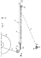
- the bags 1 fixed on the carrying tapes are useful on a cylindrical core 6 to form a roll 7 wrapped on.
- the core 6 is supported by an axis 8, which engages in the core 6 in a rotationally fixed manner.
- the Axis 8 can be suspended in a holder 9. The axis 8 and so that the roller 7 can be braked.
- the wound on the roll 7 bags 1 are from the roll 7 is withdrawn and the feed path 11 of the Opening station fed. This is done using a provided after the opening station 5 Winding device 1,2 by a not shown Stepper motor is driven.
- the winding device 12 is used to wind up the plastic bags 1 detached carrying straps 4.
- the gradual further transport the plastic bag 1 is thus carried out by means of the Winding device 12, which sections of the carrier tapes 4 winds up so that a train on the tapes 4 exercises and tensions.
- the tension of the straps 4 can be influenced by the braking device 10.
- the feed path 11 is advantageously by two in the horizontal direction of movement B of the plastic bag 1 extending angular rails 13 formed in Distance of the bag width b are arranged from each other.
- the plastic bags 1 lie with their longitudinal edges on the horizontal angle legs 13a the angle rails 13 on. Their mutual Distance is according to the respective bag width b adjustable.
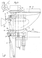
- a transverse rail 14 is provided at the opening station 5, whose underside 14a is a contact surface for the two straps 4 and also for the one above forms first building wall 2.
- an opening head 16 vertically movable arranged below and opposite the contact surface 14a.
- the vertical lifting movement of the opening head 16 is effected by a piston-cylinder unit 17.
- the opening head 16 carries at least one upwards directed suction head 18, the bottom of the Contact surface 14a is too movable.
- a gripper 19 is also arranged, which by a parallel to the opening edge 2a, 3a or also parallel to Cross rail 14 axis pivotable on the opening head 16 is stored. Serves to drive the gripper 19 a piston-cylinder unit supported on the opening head 16 21.
- the gripper 19 is angular in side view and has a terminal block 19a which of at the top of the rubber-elastic material Suction cup 18 can be pressed.
- the suction cup 18 is opposite to that in the open position the foremost pouch in the immediate vicinity the opening edge 2a, 3a arranged the same as it can be seen from Figure 5.
- the opening station 5 Opposite the opening station 5 is a horizontal and thus slide 22 that can be moved in the longitudinal direction of the bag arranged by a piston-cylinder unit 23rd is drivable.
- the carriage 22 has a horizontal Support surface 24 for the filling material, e.g. a piece of cheese, on.
- two spreading sheets 25 are arranged at the end of the opening station 5 facing Carriage 22.
- the levels of these two spreading plates extend essentially in the direction of displacement C of the slide 22nd and perpendicular to the contact surface 24.
- the spreading plates 25 are on the carriage 22 perpendicular to their planes, i.e. 1 perpendicular to the plane of the drawing, in opposite directions slidably mounted.
- For this two serve one above the other arranged guide rods 26 which are transverse to the direction of displacement C and extend horizontally.
- the spreading sheets 25 are retractable into the bag opening and closed this purpose to those facing the opening device 5 Tapered towards the end.
- Lever linkage 28 is provided, consisting of two over the common axis 29 articulated to each other in a scissor-like manner connected double-armed levers 30.
- the common Axis 29 is connected to the carriage 22.
- each lever arm of the double-armed lever 30 engages on a support 31, the associated spreader plate 25 carries.
- the other lever arm of each double arm Lever 30 is each via a handlebar 32 with a Drive head movable in the slide sliding direction C. 33 connected.
- As a drive motor for the drive head 33 serves a piston-cylinder unit carried by the carriage 22 34.
- the device works as follows:
- the bag 1st gradually pulled to the opening station 5.
- the Winding device 12 is stopped as soon as the Bag edge 2a, 3a of the foremost bag 1 the rear edge 14b of the cross rail 14 has reached.
- the stopping the winding device 12 can for example via a photocell.
- the piston-cylinder unit 17 is the opening head 16 after Move up and the suction cup 18 to the bottom the second bag wall 3 located below and placed under vacuum. If the set vacuum is reached, the opening head 16 is moved down, whereby the bottom wall 3 of the bag overhead bag wall 2, which by the tensioned Carrying straps 4 is held, slightly lifted off and the foremost bag 1 is opened a crack.
- the bag edge 2a, 3a is turned away part of the bag still held by the angle rails 13.
- the carriage 22 is now with the on the support surface 24 arranged filling material F in the direction of Opening station 5 moved, the each other approximated spreading plates 25, as can be seen from FIG. 4 into the bag opening ⁇ .
- the spreading plates 25 are moved apart in opposite directions, insofar as this is the plastic bag to be opened 1 allows.
- the gripper 19 swung into its rest position and the vacuum on Suction cup 18 lifted.
- An insertion cylinder 35 pushes the filling material F from the support surface 24 between the Spreading plates 25 into the opened bag 1 until the filling F at the closed end of the bag triggers.
- the bag is supported by carrying tapes 4 solved.
- the filled bag is placed on the roller conveyor 36 transported away.
- the filled Bag will rolled up with the winding device 12 and thus the Bag chain to the opening station 5 towards B moved until the edge of the bag 2a, 3a of the next bag again the rear edge 14b of the cross rail 14 is reached Has.
- FIGS. 6 to 8 has the same principle Structure like the previously described embodiment, so that the above Statements analogously to the embodiment shown in Figures 6 to 8 hold true.
- This embodiment is particularly suitable for plastic bags wider width.
- the horizontal feed path is 11 by a larger number of rails running perpendicular to the cross rail 14 13, 113, 213, 313 are formed, each at a distance from one another and parallel to one another are arranged. The rails are not yet used to guide and support the opened bag 1.
- the ends 13b, 113b, 213b, 313b of the rails 13, 113, 213, 313 are each at a distance from the cross rail 14 and parallel to this arranged, horizontal support rail 37 connected so that the rails of cantilever from the support rail 37 to the cross rail 14.
- the distant ends 13b, 113b, 213b, 313b are expedient, as indicated by arrows in FIG. 7, adjustable relative to the mounting rail so that it can be adjusted to the respective bag width are adjustable and can also be adapted to the respective bag length.
- the free ends 113a, 213a, 313a should be different Have a distance to the cross rail 14.
- the free ends 313a of the rails 313 which are closer to a vertical central plane E-E running parallel to the rails, should have a distance a1 from the cross rail 14 which is greater than the respective one Distance a2 of the free ends 213a and the distance a3 of the free ends 113a, rails 213 and 113, respectively, which are further outward from the central plane E-E this ensures that the bags 1 are fed along the horizontal Feed path 11 are initially adequately supported downwards and not unintentionally hang down.
Applications Claiming Priority (2)
| Application Number | Priority Date | Filing Date | Title |
|---|---|---|---|
| DE29720001U | 1997-11-11 | ||
| DE29720001U DE29720001U1 (de) | 1997-11-11 | 1997-11-11 | Vorrichtung zum Öffnen von Kunststoffbeuteln |
Publications (1)
| Publication Number | Publication Date |
|---|---|
| EP0916579A1 true EP0916579A1 (fr) | 1999-05-19 |
Family
ID=8048467
Family Applications (1)
| Application Number | Title | Priority Date | Filing Date |
|---|---|---|---|
| EP98120795A Withdrawn EP0916579A1 (fr) | 1997-11-11 | 1998-11-03 | Dispositif pour ouvrir des sacs en matière plastique |
Country Status (2)
| Country | Link |
|---|---|
| EP (1) | EP0916579A1 (fr) |
| DE (1) | DE29720001U1 (fr) |
Cited By (3)
| Publication number | Priority date | Publication date | Assignee | Title |
|---|---|---|---|---|
| FR2826633A1 (fr) * | 2001-06-28 | 2003-01-03 | Windmoeller & Hoelscher | Procede de remplissage des sachets d'une chaine de sachets ou d'une chaine de piles de sachets et un dispositif pour la mise en oeuvre du procede |
| CN113895712A (zh) * | 2021-10-18 | 2022-01-07 | 安徽采林间食品有限公司 | —种坚果包装机用包装袋的开袋机构 |
| WO2024027757A1 (fr) * | 2022-08-02 | 2024-02-08 | 王侃祺 | Dispositif de séparation d'ouverture secondaire |
Families Citing this family (1)
| Publication number | Priority date | Publication date | Assignee | Title |
|---|---|---|---|---|
| CN107499584A (zh) * | 2017-09-09 | 2017-12-22 | 江苏沃绿宝有机农业开发有限公司 | 一种肥料袋自动张开机构 |
Citations (3)
| Publication number | Priority date | Publication date | Assignee | Title |
|---|---|---|---|---|
| US4137958A (en) * | 1976-11-15 | 1979-02-06 | Golby Bag Company, Inc. | Polypropylene bag for use in an automatic filling process |
| US5421143A (en) * | 1994-10-04 | 1995-06-06 | Ag-Pak, Inc. | Bag holding and loading device for bagger |
| WO1998051571A1 (fr) * | 1997-05-16 | 1998-11-19 | Cryovac, Inc. | Procede et systeme pour ouvrir des sacs sur bandes |
-
1997
- 1997-11-11 DE DE29720001U patent/DE29720001U1/de not_active Expired - Lifetime
-
1998
- 1998-11-03 EP EP98120795A patent/EP0916579A1/fr not_active Withdrawn
Patent Citations (3)
| Publication number | Priority date | Publication date | Assignee | Title |
|---|---|---|---|---|
| US4137958A (en) * | 1976-11-15 | 1979-02-06 | Golby Bag Company, Inc. | Polypropylene bag for use in an automatic filling process |
| US5421143A (en) * | 1994-10-04 | 1995-06-06 | Ag-Pak, Inc. | Bag holding and loading device for bagger |
| WO1998051571A1 (fr) * | 1997-05-16 | 1998-11-19 | Cryovac, Inc. | Procede et systeme pour ouvrir des sacs sur bandes |
Cited By (4)
| Publication number | Priority date | Publication date | Assignee | Title |
|---|---|---|---|---|
| FR2826633A1 (fr) * | 2001-06-28 | 2003-01-03 | Windmoeller & Hoelscher | Procede de remplissage des sachets d'une chaine de sachets ou d'une chaine de piles de sachets et un dispositif pour la mise en oeuvre du procede |
| CN113895712A (zh) * | 2021-10-18 | 2022-01-07 | 安徽采林间食品有限公司 | —种坚果包装机用包装袋的开袋机构 |
| CN113895712B (zh) * | 2021-10-18 | 2022-10-14 | 安徽采林间食品有限公司 | 一种坚果包装机用包装袋的开袋机构 |
| WO2024027757A1 (fr) * | 2022-08-02 | 2024-02-08 | 王侃祺 | Dispositif de séparation d'ouverture secondaire |
Also Published As
| Publication number | Publication date |
|---|---|
| DE29720001U1 (de) | 1999-03-25 |
Similar Documents
| Publication | Publication Date | Title |
|---|---|---|
| EP0085399B1 (fr) | Procédé et appareil pour introduire automatiquement des sacs parallélépipédiques | |
| EP0522110A1 (fr) | Procede pour la mise a disposition automatique de sacs et dispositif d'accrochage de sacs. | |
| WO2012104251A1 (fr) | Dispositif et procédé d'étiquetage d'emballages individuels depuis le côté inférieur de l'emballage | |
| EP0243906B1 (fr) | Procédé et dispositif pour faire des paquets tubulaires portatifs d'imprimés comme des journaux, des revues et similaires | |
| DE3723601A1 (de) | Maschine zum wickeln einer papier- oder kartonbahn | |
| DE60009209T2 (de) | Verpackungsvorrichtung und Verfahren zum Einwickeln von flachen Gegenständen, wie Büchern | |
| CH656861A5 (de) | Vorrichtung zum lagern von papierbogen. | |
| EP0336904A2 (fr) | Appareil de transport des plaques d'impression | |
| DE2026860B2 (de) | Vorrichtung zur Verpackung von Gütern durch Aufsetzen eines Schlauches | |
| DE2942883C2 (de) | Vorrichtung zum Verschließen des Bodens einer rechteckigen aufgerichteten Faltschachtel | |
| DE60107896T2 (de) | Methode und Vorrichtung zum Herstellen von Verpackungen mit Oberfolie | |
| DE4116311C2 (de) | Vorrichtung zum automatischen Anhängen von Schüttgutsäcken | |
| DE19749825A1 (de) | Vorrichtung zum Öffnen von Kunststoffbeuteln | |
| DE10204313A1 (de) | Verfahren und Vorrichtung zum Abschneiden von Etikettenhülsen von einem flachliegenden Etikettenschlauchband | |
| EP0916579A1 (fr) | Dispositif pour ouvrir des sacs en matière plastique | |
| EP0161406B1 (fr) | Dispositif pour replier sur la partie supérieure d'un sac muni d'une bande adhésive, les languettes dépassant sur les côtés du sac rempli | |
| EP1201539A1 (fr) | Dispositif pour fabriquer et de préférence remplir et fermer des sacs en matière plastique | |
| DE4008592A1 (de) | Vorrichtung zum automatischen Zu- und Abführen von Platten aus Karton, Wellpappe und dergl., zu einer Stanz- und/oder Druckmaschine | |
| DE102008048831A1 (de) | Fördervorrichtung für eine Verpackungsmaschine | |
| EP0014246A1 (fr) | Procédé pour déposer, stocker et distribuer, d'une manière rangée, des objets plats individuels, en particulier des sacs en matière plastique | |
| DE4416540C1 (de) | Verfahren und Vorrichtung zum Umwickeln von Quadern, insbesondere Isolierstoffballen, mit Einwickelmaterial | |
| DE3234929C2 (de) | Vorrichtung zum Überziehen eines Gutstapels mit einer Haube aus wärmeschrumpffähigem Kunststoff | |
| EP2670673B1 (fr) | Dispositif et procédé d'étiquetage d'emballages individuels depuis le côté inférieur de l'emballage | |
| DE3440416C2 (fr) | ||
| DE1486061A1 (de) | Anordnung zum OEffnen und/oder Fuehren von Beuteln,Taschen od.dgl. |
Legal Events
| Date | Code | Title | Description |
|---|---|---|---|
| PUAI | Public reference made under article 153(3) epc to a published international application that has entered the european phase |
Free format text: ORIGINAL CODE: 0009012 |
|
| AK | Designated contracting states |
Kind code of ref document: A1 Designated state(s): AT CH DE DK ES FI FR GB GR IE IT LI NL PT SE |
|
| AX | Request for extension of the european patent |
Free format text: AL;LT;LV;MK;RO;SI |
|
| 17P | Request for examination filed |
Effective date: 19990723 |
|
| AKX | Designation fees paid |
Free format text: AT CH DE DK ES FI FR GB GR IE IT LI NL PT SE |
|
| 17Q | First examination report despatched |
Effective date: 20000522 |
|
| GRAG | Despatch of communication of intention to grant |
Free format text: ORIGINAL CODE: EPIDOS AGRA |
|
| STAA | Information on the status of an ep patent application or granted ep patent |
Free format text: STATUS: THE APPLICATION HAS BEEN WITHDRAWN |
|
| 18W | Application withdrawn |
Withdrawal date: 20010922 |