EP0916579A1 - Plastic bags opening device - Google Patents
Plastic bags opening device Download PDFInfo
- Publication number
- EP0916579A1 EP0916579A1 EP98120795A EP98120795A EP0916579A1 EP 0916579 A1 EP0916579 A1 EP 0916579A1 EP 98120795 A EP98120795 A EP 98120795A EP 98120795 A EP98120795 A EP 98120795A EP 0916579 A1 EP0916579 A1 EP 0916579A1
- Authority
- EP
- European Patent Office
- Prior art keywords
- opening
- bag
- rails
- bags
- bag wall
- Prior art date
- Legal status (The legal status is an assumption and is not a legal conclusion. Google has not performed a legal analysis and makes no representation as to the accuracy of the status listed.)
- Withdrawn
Links
Images


Classifications
-
- B—PERFORMING OPERATIONS; TRANSPORTING
- B65—CONVEYING; PACKING; STORING; HANDLING THIN OR FILAMENTARY MATERIAL
- B65B—MACHINES, APPARATUS OR DEVICES FOR, OR METHODS OF, PACKAGING ARTICLES OR MATERIALS; UNPACKING
- B65B43/00—Forming, feeding, opening or setting-up containers or receptacles in association with packaging
- B65B43/26—Opening or distending bags; Opening, erecting, or setting-up boxes, cartons, or carton blanks
- B65B43/30—Opening or distending bags; Opening, erecting, or setting-up boxes, cartons, or carton blanks by grippers engaging opposed walls, e.g. suction-operated
-
- B—PERFORMING OPERATIONS; TRANSPORTING
- B65—CONVEYING; PACKING; STORING; HANDLING THIN OR FILAMENTARY MATERIAL
- B65B—MACHINES, APPARATUS OR DEVICES FOR, OR METHODS OF, PACKAGING ARTICLES OR MATERIALS; UNPACKING
- B65B43/00—Forming, feeding, opening or setting-up containers or receptacles in association with packaging
- B65B43/26—Opening or distending bags; Opening, erecting, or setting-up boxes, cartons, or carton blanks
- B65B43/267—Opening of bags interconnected in a web
Definitions
- the invention relates to a device for opening plastic bags, the scaly on top of each other on at least two at a distance from each other and
- the straps that run vertically to the opening edge of the pouches are detachably glued are, with a substantially horizontal feed path along which the Plastic bag of an opening station by pulling the straps gradually can be supplied with a contact surface provided at the opening station which the opening-side area of the first bag wall through the tensioned Carrying straps is held and fixed, with a pneumatic opening device, by means of which the opposite second bag wall from the first bag wall can be lifted off to open the bag, and with a roller conveyor for removal filled bag from the opening station, as well as with a subsequent to the Opening station arranged winding device for winding the of the Plastic bags detached carrier tapes.
- Plastic bags are the plastic bags lying on top of each other in scales gradually over the roller conveyor and pulled a table adjoining this and arranged at the opening station.
- the table forms a continuous contact surface (support surface) for the Plastic bag.
- a stock of plastic bags is in a box below the table.
- the pouch is transported step by step by the wrapping device, with which the straps drawn over the front edge of the table are wound up become. If the foremost and uppermost bags have a sensor arranged on the table reached, the winding device is stopped and by means of several air nozzles where air flows out, the bag is opened.
- a device for opening bags is known, a gripper is arranged on an opening head, which is parallel to the Opening edge of the axis of the bag is pivoted on the opening head and after the initial lifting of the second bag wall on the inside like this can be pressed that the second bag wall is clamped between the gripper and suction cup becomes.
- this opening device is for special, vertically arranged bags provided, of which several are combined to form a block.
- the top ends of a bag wall similar to the leaves of one Tear-off calendar, held in a holder, being between the upper ends of the one bag wall and the rest of the same, a perforation is provided is.
- the second wall of the bag only extends to the level of the perforation.
- the invention is therefore based on the object of a device for opening To create plastic bags of the type mentioned that are reliable and works trouble-free, and in particular a reliable opening of non-powdered and possibly electrostatically charged plastic bags of all kinds and there is also no risk of contamination for the bags.
- the feed path is at a distance Arranged above the roller conveyor and a cross rail at the end of the infeed conveyor is provided, the underside of which forms the contact surface that the pneumatic Opening device comprises at least one suction cup, which on a vertical to the contact surface vertically movable opening head is arranged from below the contact surface is too movable and the second one is initially lifted off Bag wall is used, and that a gripper is arranged on the opening head, which around an axis running parallel to the crossbar is pivotally mounted on the opening head and after the initial lifting of the second bag wall on the inside so can be pressed that the second bag wall is clamped between the gripper and suction cup becomes.
- the invention is therefore based on the idea that the feed path for the Arrange plastic bags at a distance above the roller conveyor.
- This has the significant advantage that what the bags when not fully opening a bag should hardly occur in the device according to the invention, no longer by Moving the contents, e.g. Cheese that can be contaminated as it is above the Roller conveyor are arranged. Even empty bags cannot fall through Fill pieces or other foreign matter are contaminated. You stay in Clean the area around the opening station so that there are no faults on the suction cup can.
- filled bags are only ever on the roller conveyor transported away and do not have to, as in the known known Only move the device over unfilled bags. This is another Source of interference avoided.
- the respective plastic bag is opened by the interaction of one or more suction cups with a mechanical gripper.
- suction cup and Grippers powder-free and also statically charged plastic bags of any kind see above e.g. Tubular bags, sealed edge bags, shrink bags and the like with the largest Reliability and trouble-free opening.
- the opening of the pouch is because the second bag wall is pulled down from the cross rail by suction cup, favored by gravity.
- suction cup Gripper which lies against the inside of the second bag wall and the second Bag wall presses on the suction cup made of rubber-elastic material, considerable tensile forces can be exerted on the bag wall, so that reliable it is prevented that the bag wall unintentionally from the opening head when opening solves. Opening can also be accelerated. Since opening the bag without Blowing air flows, no bacteria or other contaminants can occur in the bag be blown.
- the plastic bags 1 are rectangular in the flat state. Lie flat in each case two plastic films, subsequently as the first bag wall 2 and second Bag wall 3 referred to each other, which are interconnected at three edges. At the fourth, front edge, which is referred to as the bag edge 2a or 3a, are the the two plastic films are not connected. Along this edge of the bag 2a, 3a the frontmost plastic bag should be opened.
- the plastic bags 1 are manufactured as a so-called chain bag. There is a series of plastic bags 1 scaly on top of each other. The bags 1 are on two at a distance from each other and perpendicular to the opening edge 2a, 2b of the bag 1 extending support straps 4 detachable glued on.
- the bags 1 of the opening station 5 fed horizontally so that the Tragbyerar 4 are above and thus to the top glued outside of the first bag wall 2 glued are.
- the distance between the opening edges 2a, 3a of two successive, scale-like one above the other For example, component 1 is approximately 40 mm.
- Each bag 1 is only in this area of approximately 40 mm connected to the two straps 4.
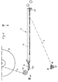
- the bags 1 fixed on the carrying tapes are useful on a cylindrical core 6 to form a roll 7 wrapped on.
- the core 6 is supported by an axis 8, which engages in the core 6 in a rotationally fixed manner.
- the Axis 8 can be suspended in a holder 9. The axis 8 and so that the roller 7 can be braked.
- the wound on the roll 7 bags 1 are from the roll 7 is withdrawn and the feed path 11 of the Opening station fed. This is done using a provided after the opening station 5 Winding device 1,2 by a not shown Stepper motor is driven.
- the winding device 12 is used to wind up the plastic bags 1 detached carrying straps 4.
- the gradual further transport the plastic bag 1 is thus carried out by means of the Winding device 12, which sections of the carrier tapes 4 winds up so that a train on the tapes 4 exercises and tensions.
- the tension of the straps 4 can be influenced by the braking device 10.
- the feed path 11 is advantageously by two in the horizontal direction of movement B of the plastic bag 1 extending angular rails 13 formed in Distance of the bag width b are arranged from each other.
- the plastic bags 1 lie with their longitudinal edges on the horizontal angle legs 13a the angle rails 13 on. Their mutual Distance is according to the respective bag width b adjustable.
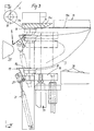
- a transverse rail 14 is provided at the opening station 5, whose underside 14a is a contact surface for the two straps 4 and also for the one above forms first building wall 2.
- an opening head 16 vertically movable arranged below and opposite the contact surface 14a.
- the vertical lifting movement of the opening head 16 is effected by a piston-cylinder unit 17.
- the opening head 16 carries at least one upwards directed suction head 18, the bottom of the Contact surface 14a is too movable.
- a gripper 19 is also arranged, which by a parallel to the opening edge 2a, 3a or also parallel to Cross rail 14 axis pivotable on the opening head 16 is stored. Serves to drive the gripper 19 a piston-cylinder unit supported on the opening head 16 21.
- the gripper 19 is angular in side view and has a terminal block 19a which of at the top of the rubber-elastic material Suction cup 18 can be pressed.
- the suction cup 18 is opposite to that in the open position the foremost pouch in the immediate vicinity the opening edge 2a, 3a arranged the same as it can be seen from Figure 5.
- the opening station 5 Opposite the opening station 5 is a horizontal and thus slide 22 that can be moved in the longitudinal direction of the bag arranged by a piston-cylinder unit 23rd is drivable.
- the carriage 22 has a horizontal Support surface 24 for the filling material, e.g. a piece of cheese, on.
- two spreading sheets 25 are arranged at the end of the opening station 5 facing Carriage 22.
- the levels of these two spreading plates extend essentially in the direction of displacement C of the slide 22nd and perpendicular to the contact surface 24.
- the spreading plates 25 are on the carriage 22 perpendicular to their planes, i.e. 1 perpendicular to the plane of the drawing, in opposite directions slidably mounted.
- For this two serve one above the other arranged guide rods 26 which are transverse to the direction of displacement C and extend horizontally.
- the spreading sheets 25 are retractable into the bag opening and closed this purpose to those facing the opening device 5 Tapered towards the end.
- Lever linkage 28 is provided, consisting of two over the common axis 29 articulated to each other in a scissor-like manner connected double-armed levers 30.
- the common Axis 29 is connected to the carriage 22.
- each lever arm of the double-armed lever 30 engages on a support 31, the associated spreader plate 25 carries.
- the other lever arm of each double arm Lever 30 is each via a handlebar 32 with a Drive head movable in the slide sliding direction C. 33 connected.
- As a drive motor for the drive head 33 serves a piston-cylinder unit carried by the carriage 22 34.
- the device works as follows:
- the bag 1st gradually pulled to the opening station 5.
- the Winding device 12 is stopped as soon as the Bag edge 2a, 3a of the foremost bag 1 the rear edge 14b of the cross rail 14 has reached.
- the stopping the winding device 12 can for example via a photocell.
- the piston-cylinder unit 17 is the opening head 16 after Move up and the suction cup 18 to the bottom the second bag wall 3 located below and placed under vacuum. If the set vacuum is reached, the opening head 16 is moved down, whereby the bottom wall 3 of the bag overhead bag wall 2, which by the tensioned Carrying straps 4 is held, slightly lifted off and the foremost bag 1 is opened a crack.
- the bag edge 2a, 3a is turned away part of the bag still held by the angle rails 13.
- the carriage 22 is now with the on the support surface 24 arranged filling material F in the direction of Opening station 5 moved, the each other approximated spreading plates 25, as can be seen from FIG. 4 into the bag opening ⁇ .
- the spreading plates 25 are moved apart in opposite directions, insofar as this is the plastic bag to be opened 1 allows.
- the gripper 19 swung into its rest position and the vacuum on Suction cup 18 lifted.
- An insertion cylinder 35 pushes the filling material F from the support surface 24 between the Spreading plates 25 into the opened bag 1 until the filling F at the closed end of the bag triggers.
- the bag is supported by carrying tapes 4 solved.
- the filled bag is placed on the roller conveyor 36 transported away.
- the filled Bag will rolled up with the winding device 12 and thus the Bag chain to the opening station 5 towards B moved until the edge of the bag 2a, 3a of the next bag again the rear edge 14b of the cross rail 14 is reached Has.
- FIGS. 6 to 8 has the same principle Structure like the previously described embodiment, so that the above Statements analogously to the embodiment shown in Figures 6 to 8 hold true.
- This embodiment is particularly suitable for plastic bags wider width.
- the horizontal feed path is 11 by a larger number of rails running perpendicular to the cross rail 14 13, 113, 213, 313 are formed, each at a distance from one another and parallel to one another are arranged. The rails are not yet used to guide and support the opened bag 1.
- the ends 13b, 113b, 213b, 313b of the rails 13, 113, 213, 313 are each at a distance from the cross rail 14 and parallel to this arranged, horizontal support rail 37 connected so that the rails of cantilever from the support rail 37 to the cross rail 14.
- the distant ends 13b, 113b, 213b, 313b are expedient, as indicated by arrows in FIG. 7, adjustable relative to the mounting rail so that it can be adjusted to the respective bag width are adjustable and can also be adapted to the respective bag length.
- the free ends 113a, 213a, 313a should be different Have a distance to the cross rail 14.
- the free ends 313a of the rails 313 which are closer to a vertical central plane E-E running parallel to the rails, should have a distance a1 from the cross rail 14 which is greater than the respective one Distance a2 of the free ends 213a and the distance a3 of the free ends 113a, rails 213 and 113, respectively, which are further outward from the central plane E-E this ensures that the bags 1 are fed along the horizontal Feed path 11 are initially adequately supported downwards and not unintentionally hang down.
Landscapes
- Engineering & Computer Science (AREA)
- Mechanical Engineering (AREA)
- Control And Other Processes For Unpacking Of Materials (AREA)
- Supplying Of Containers To The Packaging Station (AREA)
Abstract
Description
Die Erfindung betrifft eine Vorrichtung zum Öffnen von Kunststoffbeuteln, die schuppenförmig übereinanderliegend an mindestens zwei in Abstand voneinander und serkrecht zum Öffnungsrand der Beutel verlaufenden Tragbändern lösbar angeklebt sind, mit einer im wesentlichen horizontalen Zuführbahn, entlang derer die Kunststoffbeutel einer Öffnungsstation durch Zug an den Tragbändern schrittweise zuführbar sind, mit einer an der Öffnungsstation vorgesehenen Anlagefläche, an welcher der öffnungsseitige Bereich der ersten Beutelwand durch die gespannten Tragbänder gehalten und fixiert ist, mit einer pneumatischen Öffnungseinrichtung, mittels welcher die gegenüberliegende zweite Beutelwand von der ersten Beutelwand zur Öffnung des Beutels abhebbar ist, und mit einer Rollenbahn zum Abtransport gefüllter Beutel von der Öffnungsstation, sowie mit einer anschließend an die Öffnungsstation angeordneten Wickeleinrichtung zum Aufwickeln der von den Kunststoffbeuteln losgelösten Tragbänder.The invention relates to a device for opening plastic bags, the scaly on top of each other on at least two at a distance from each other and The straps that run vertically to the opening edge of the pouches are detachably glued are, with a substantially horizontal feed path along which the Plastic bag of an opening station by pulling the straps gradually can be supplied with a contact surface provided at the opening station which the opening-side area of the first bag wall through the tensioned Carrying straps is held and fixed, with a pneumatic opening device, by means of which the opposite second bag wall from the first bag wall can be lifted off to open the bag, and with a roller conveyor for removal filled bag from the opening station, as well as with a subsequent to the Opening station arranged winding device for winding the of the Plastic bags detached carrier tapes.
Bei einer derartigen, aus der DE 40 08 402 A1 bekannten Vorrichtung zum Öffnen von Kunststoffbeuteln werden die durch die Tragbänder miteinander verbundenen, schuppenartig übereinanderliegenden Kunststoffbeutel schrittweise über die Rollenbahn und einen an diese anschließenden, an der Öffnungsstation angeordneten Tisch gezogen. Der Tisch bildet eine durchgehende Anlagefläche (Auflagefläche) für die Kunststoffbeutel. Ein Vorrat an Kunststoffbeuteln befindet sich in einem Karton unter dem Tisch. Der schrittweise Transport der Beutel erfolgt durch die Wickeleinrichtung, mit welcher die über die Vorderkante des Tisches gezogenen Tragbänder aufgewickelt werden. Wenn der vorderste und oberste Beutel einen am Tisch angeordneten Sensor erreicht hat, wird die Wickeleinrichtung stillgesetzt und mittels mehrerer Luftdüsen, aus denen Luftströme austreten, der Beutel geöffnet. Hierbei wird die unten liegende erste Beutelwand von den Tragbändern an der Anlagefläche des Tisches gehalten, während die zweite, oben liegende Beutelwand von den Luftströmen angehoben und damit der Beutel geöffnet wird. Nach dem Öffnen des Beutels wird eine trichterförmige Schute in den aufgeblähten vordersten Beutel gefahren und ein Zylinder drückt das Füllgut, z.B. ein Käsestück, durch die Schute in den Beutel. Dabei wird der vorderste, gefüllte Beutel von den Tragbändern gelöst und über die Rollenbahn abtransportiert. Das Öffnen der Kunststoffbeutel mittels Blasluftströmen ist jedoch nicht besonders zuverlässig und es funktioniert nur bei Beuteln, die gepudert sind und deren einander zugekehrte Beutelwände infolge der Puderung nicht aneinanderhaften. Bei ungepuderten Kunststoffbeuteln haften die einander zugekehrten Innenseiten der beiden Beutelwände, bedingt auch durch statische Aufladung, so stark aneinander, daß ein zuverlässiges Öffnen mit Blasluftströmen nicht gewährleistet ist. Nicht oder nur teilweise geöffnete Beutel führen zu Störungen, die eine Betriebsunterbrechung bedingen und außerdem auch eine Bedienungsperson zur Behebung von Störungen erfordern. Wird ein Beutel nicht vollständig geöffnet, dann wird das Käsestück über die auf dem Tisch und der Rollenbahn liegenden Beutel geschoben und diese werden verschmutzt. Ähnliches passiert, wenn Teile des Füllgutes auf den Tisch gelangen. Diese werden von dem jeweils gefüllten Beutel über die auf der Rollenbahn liegenden geschoben und verschmutzen diese. Außerdem besteht auch die Gefahr, daß beim Verschieben eines gefüllten Beutels über ungefüllte Beutel, diese von den Tragbändern abgerissen werden, was ebenfalls zu Störungen führt. Nachteilig ist weiterhin, daß durch die Blasluftströme Bakterien und sonstige Verschmutzungen in den geöffneten Beutel gelangen können. Die in einem Karton unterhalb des Tisches bevorrateten Beutel können außerdem durch herabfallende Produktstücke und andere Fremdstoffe verschmutzt werden.In such a device known from DE 40 08 402 A1 for opening Plastic bags are the plastic bags lying on top of each other in scales gradually over the roller conveyor and pulled a table adjoining this and arranged at the opening station. The table forms a continuous contact surface (support surface) for the Plastic bag. A stock of plastic bags is in a box below the table. The pouch is transported step by step by the wrapping device, with which the straps drawn over the front edge of the table are wound up become. If the foremost and uppermost bags have a sensor arranged on the table reached, the winding device is stopped and by means of several air nozzles where air flows out, the bag is opened. This will be the first one below Bag wall held by the straps on the table's abutment surface while the second, top wall of the bag is lifted by the air currents and thus the Bag is opened. After opening the bag, a funnel-shaped barge is put in moved the inflated foremost pouch and a cylinder presses the contents, e.g. a piece of cheese, through the barge into the bag. The frontmost, filled bag detached from the carrying belts and transported away via the roller conveyor. Opening the However, plastic bags using blown air flows are not particularly reliable and it is only works with bags that are powdered and facing each other Do not stick the bag walls together as a result of the powdering. In powdered Plastic bags adhere to the mutually facing inner sides of the two bag walls, also due to static charge, so strongly against each other that a reliable Opening with blown air flows is not guaranteed. Not open or only partially open Bags lead to malfunctions that cause business interruption and also also require an operator to troubleshoot problems. Becomes a bag not fully opened, then the piece of cheese is placed over the on the table and the Bags lying on the roller conveyor are pushed and these become dirty. Similar thing happens when parts of the filling material reach the table. These are from the each filled bag pushed over the lying on the roller conveyor and pollute this. There is also a risk that when moving a filled bags over unfilled bags, these are torn off the carrying straps, which also leads to interference. Another disadvantage is that the blown air flows Bacteria and other contaminants can get into the opened bag. The bags stored in a box under the table can also be used falling product pieces and other foreign matter are contaminated.
Aus der US-A-3 331 182 ist eine Vorrichtung zum Öffnen von schuppenförmig übereinanderliegenden Kunststoffbeuteln bekannt, bei welcher zum Öffnen der Beutel ein Saugnapf vorgesehen ist. Die Beutel werden entlang einer im wesentlichen vertikalen Führungsbahn von unten nach oben geführt. An der Öffnungsstation wird der horizontal verschiebbare Saugnapf an die den Tragbändern abgewandte Beutelwand des obersten Beutels herangeführt, um dann diese Beutelwand von der ersten Beutelwand abzuheben. From US-A-3 331 182 a device for opening scale-like is Plastic bags lying one above the other are known, in which the bags are opened a suction cup is provided. The bags are essentially along one vertical guideway from bottom to top. At the opening station the horizontally displaceable suction cup on the bag wall facing away from the carrying straps top bag, then this bag wall from the first bag wall to take off.
Ferner ist aus der US-A-5 421 143 eine Vorrichtung zum Öffnen von Beuteln bekannt, wobei an einem Öffnungskopf ein Greifer angeordnet ist, welcher um eine parallel zum Öffnungsrand der Beutel verlaufende Achse schwenkbar am Öffnungskopf gelagert und nach dem anfänglichen Abheben der zweiten Beutelwand an deren Innenseite so andrückbar ist, daß die zweite Beutelwand zwischen Greifer und Saugnapf geklemmt wird. Diese Öffnungsvorrichtung ist jedoch für spezielle, vertikal angeordnete Beutel vorgesehen, von denen jeweils mehrere zu einem Block zusammengefaßt sind. Die oberen Enden jeweils einer Beutelwand sind, ähnlich wie die Blätter eines Abreißkalenders, in einer Halterung gehalten, wobei zwischen den oberen Enden der jeweils einen Beutelwand und dem übrigen Teil derselben, eine Perforation vorgesehen ist. Die zweite Beutelwand erstreckt sich nur bis zur Höhe der Perforation. Diese bekannte Vorrichtung setzt also bestimmte blockartig zusammengefaßte Beutel voraus, deren Herstellung teuer ist.From US-A-5 421 143 a device for opening bags is known, a gripper is arranged on an opening head, which is parallel to the Opening edge of the axis of the bag is pivoted on the opening head and after the initial lifting of the second bag wall on the inside like this can be pressed that the second bag wall is clamped between the gripper and suction cup becomes. However, this opening device is for special, vertically arranged bags provided, of which several are combined to form a block. The top ends of a bag wall, similar to the leaves of one Tear-off calendar, held in a holder, being between the upper ends of the one bag wall and the rest of the same, a perforation is provided is. The second wall of the bag only extends to the level of the perforation. This the known device therefore requires certain bags combined in blocks, their manufacture is expensive.
Der Erfindung liegt daher die Aufgabe zugrunde, eine Vorrichtung zum Öffnen von Kunststoffbeuteln der eingangs erwähnten Art zu schaffen, die zuverlässig und störungsfrei arbeitet, sowie insbesondere ein zuverlässiges Öffnen von nichtgepuderten und gegebenenfalls elektrostatisch aufgeladenen Kunststoffbeuteln aller Art ermöglicht und bei der auch keine Verschmutzungsgefahr für die Beutel besteht.The invention is therefore based on the object of a device for opening To create plastic bags of the type mentioned that are reliable and works trouble-free, and in particular a reliable opening of non-powdered and possibly electrostatically charged plastic bags of all kinds and there is also no risk of contamination for the bags.
Dies wird nach der Erfindung dadurch erreicht, daß die Zuführbahn mit Abstand oberhalb der Rollenbahn angeordnet und am Ende der Zuführbahn eine Querschiene vorgesehen ist, deren Unterseite die Anlagefläche bildet, daß die pneumatische Öffnungsvorrichtung mindestens einen Saugnapf umfaßt, welcher an einem senkrecht zur Anlagefläche vertikal beweglichen Öffnungskopf angeordnet ist, von unten her auf die Anlagefläche zu beweglich ist, und zum anfänglichen Abheben der zweiten Beutelwand dient, und daß an dem Öffnungskopf ein Greifer angeordnet ist, welcher um eine parallel zur Querschiene verlaufende Achse schwenkbar am Öffnungskopf gelagert und nach dem anfänglichen Abheben der zweiten Beutelwand an deren Innenseite so andrückbar ist, daß die zweite Beutelwand zwischen Greifer und Saugnapf geklemmt wird. This is achieved according to the invention in that the feed path is at a distance Arranged above the roller conveyor and a cross rail at the end of the infeed conveyor is provided, the underside of which forms the contact surface that the pneumatic Opening device comprises at least one suction cup, which on a vertical to the contact surface vertically movable opening head is arranged from below the contact surface is too movable and the second one is initially lifted off Bag wall is used, and that a gripper is arranged on the opening head, which around an axis running parallel to the crossbar is pivotally mounted on the opening head and after the initial lifting of the second bag wall on the inside so can be pressed that the second bag wall is clamped between the gripper and suction cup becomes.
Die Erfindung geht also von dem Gedanken aus, die Zuführbahn für die Kunststoffbeutel mit Abstand oberhalb der Rollenbahn anzuordnen. Dies hat den wesentlichen Vorteil, daß die Beutel bei nicht vollständigem Öffnen eines Beutels, was bei der erfindungsgemäßen Vorrichtung kaum vorkommen dürfte, nicht mehr durch Verschieben des Füllgutes, z.B. Käse, verschmutzt werden können, da sie oberhalb der Rollenbahn angeordnet sind. Es können auch leere Beutel nicht durch herabfallende Füllgutstücke oder andere Fremdstoffe verschmutzt werden. Sie bleiben auch im Bereich der Öffnungsstation sauber, so daß keine Störungen am Saugnapf eintreten können. Außerdem werden gefüllte Beutel immer nur über die Rollenbahn abtransportiert und müssen nicht, wie bei der eingangs erwähnten bekannten Vorrichtung erst über ungefüllte Beutel verschoben werden. Hierdurch ist eine weitere Störungsquelle vermieden. Das Öffnen des jeweiligen Kunststoffbeutels erfolgt durch das Zusammenwirken eines oder mehrerer Saugnäpfe mit einem mechanischen Greifer. Wie die Praxis gezeigt hat, können durch das Zusammenwirken von Saugnapf und Greifer ungepuderte und auch statisch aufgeladene Kunststoffbeutel jeglicher Art, so z.B. Schlauchbeutel, Siegelrandbeutel, Schrumpfbeutel und dgl. mit größter Zuverlässigkeit und störungsfrei geöffnet werden. Das Öffnen der Beutel wird, da die zweite Beutelwand durch Saugnapf von der Querschiene aus nach unten gezogen wird, durch die Schwerkraft begünstigt. Durch den zusätzlich zum Saugnapf arbeitenden Greifer, der sich an die Innenseite der zweiten Beutelwand anlegt und dabei die zweite Beutelwand auf den aus gummielastischem Material bestehenden Saugnapf preßt, können erhebliche Zugkräfte auf die Beutelwand ausgeübt werden, so daß zuverlässig verhindert wird, daß sich die Beutelwand beim Öffnen ungewollt vom Öffnungskopf löst. Auch kann das Öffnen beschleunigt werden. Da das Öffnen der Beutel ohne Blasluftströme erfolgt, können auch keine Bakterien oder sonstige Verschmutzungen in den Beutel eingeblasen werden.The invention is therefore based on the idea that the feed path for the Arrange plastic bags at a distance above the roller conveyor. This has the significant advantage that what the bags when not fully opening a bag should hardly occur in the device according to the invention, no longer by Moving the contents, e.g. Cheese that can be contaminated as it is above the Roller conveyor are arranged. Even empty bags cannot fall through Fill pieces or other foreign matter are contaminated. You stay in Clean the area around the opening station so that there are no faults on the suction cup can. In addition, filled bags are only ever on the roller conveyor transported away and do not have to, as in the known known Only move the device over unfilled bags. This is another Source of interference avoided. The respective plastic bag is opened by the interaction of one or more suction cups with a mechanical gripper. As practice has shown, the interaction of suction cup and Grippers powder-free and also statically charged plastic bags of any kind, see above e.g. Tubular bags, sealed edge bags, shrink bags and the like with the largest Reliability and trouble-free opening. The opening of the pouch is because the second bag wall is pulled down from the cross rail by suction cup, favored by gravity. By working in addition to the suction cup Gripper, which lies against the inside of the second bag wall and the second Bag wall presses on the suction cup made of rubber-elastic material, considerable tensile forces can be exerted on the bag wall, so that reliable it is prevented that the bag wall unintentionally from the opening head when opening solves. Opening can also be accelerated. Since opening the bag without Blowing air flows, no bacteria or other contaminants can occur in the bag be blown.
Vorteilhafte Ausgestaltungen der Erfindung sind in den Unteransprüchen gekennzeichnet. Advantageous embodiments of the invention are in the subclaims featured.
Die Erfindung ist in folgendem, anhand von in der Zeichnung dargestellten
Ausführungsbeispielen näher erläutert. Es zeigen:
Die Kunststoffbeutel 1 sind in flachem Zustand rechteckig. Im flachen Zustand liegen
jeweils zwei Kunststoffolien, nachfolgend als erste Beutelwand 2 und zweite
Beutelwand 3 bezeichnet, aufeinander, die an drei Rändern miteinander verbunden sind.
Am vierten, vorderen Rand, der als Beutelrand 2a bzw. 3a bezeichnet wird, sind die
beiden Kunststoffolien nicht miteinander verbunden. Längs dieses Beutelrandes 2a, 3a
soll der jeweils vorderste Kunststoffbeutel geöffnet werden. Die Kunststoffbeutel 1 sind
als sogenannte Kettenbeutel hergestellt. Dabei liegt eine Serie von Kunststoffbeuteln 1
schuppenförmig übereinander. Die Beutel 1 sind an zwei
in Abstand voneinander und senkrecht zum Öffnungsrand
2a, 2b der Beutel 1 verlaufenden Tragbändern 4 lösbar
angeklebt. Bei der gezeigten vorteilhaften Ausführungsform
der Vorrichtung werden die Beutel 1 der Öffnungsstation
5 horizontalliegend so zugeführt, daß die
Tragbändar 4 oben liegen und somit an die nach oben
gekehrte Außenseite der ersten Beutelwand 2 angeklebt
sind. Der Abstand der Öffnungsränder 2a, 3a zweier
aufeinanderfolgender, schuppenförmig übereinanderliegender
Bautel 1 beträgt beispielsweise ca. 40 mm.
Jeder Beutel 1 ist nur in diesem Bereich von ca. 40 mm
mit den beiden Tragbändern 4 verbunden.The
Die an den Tragbändern fixierten Beutel 1 sind zweckmäßig
auf einem zylindrischen Kern 6 zu einer Rolle 7
auf gewickelt. Der Kern 6 wird von einer Achse 8 getragen,
die drehfest in den Kern 6 eingreift. Die
Achse 8 kann in eine Halterung 9 eingehängt werden.
Mittels einer Bremsvorrichtung 10 ist die Achse 8 und
damit auch die Rolle 7 abbremsbar.The
Die auf der Rolle 7 aufgewickelten Beutel 1 werden von
der Rolle 7 abgezogen und über eine Zuführbahn 11 der
Öffnungsstation zugeführt. Dies erfolgt mittels einer
im Anschluß an die Öffnungsstation 5 vorgesehenen
Wickeleinrichtung 1,2, die durch einen nicht dargestellten
Schrittmotor angetrieben wird. Die Wickeleinrichtung
12 dient zum Aufwickeln der von den Kunststoffbeuteln 1
losgelösten Tragbänder 4. Der schrittweise Weitertransport
der Kunststoffbeutel 1 erfolgt also mittels der
Wickeleinrichtung 12, welche die Tragbänder 4 abschnittsweise
aufwickelt, damit einen Zug auf die Tragbänder 4
ausübt und diese spannt. Die Spannung der Tragbänder 4
kann durch die Bremseinrichtung 10 beeinflußt werden.The wound on the
Die Zuführbahn 11 wird zweckmäßig durch zwei in der
horizontalen Bewegungsrichtung B der Kunststoffbeutel 1
verlaufende Winkelprofilschienen 13 gebildet, die im
Abstand der Beutelbreite b voneinander angeordnet sind.
Die Kunststoffbeutel 1 liegen mit ihren Längsrändern
auf den horizontal verlaufenden Winkelschenkeln 13a
der Winkelprofilschienen 13 auf. Deren gegenseitiger
Abstand ist entsprechend der jeweiligen Beutelbreite b
einstellbar.The
An der Öffnungsstation 5 ist eine Querschiene 14 vorgesehen,
deren Unterseite 14a eine Anlagefläche für
die beiden Tragbänder 4 und auch für die oben liegende
erste Bautelwand 2 bildet. Durch die Wickeleinrichtung 12
werden die von den Beutein 1 gelösten und über die
Umlenkrollen 15 geführten Tragbänder gespannt und in
Anlage an der Anlagefläche 14a gehalten.A
Unterhalb und gegenüberliegend der Anlagefläche 14a ist
ein Öffnungskopf 16 in vertikaler Richtung höhenbeweglich
angeordnet. Die vertikale Hubbewegung des Öffnungskopfes
16 wird durch eine Kolben-Zylinder-Einheit 17 bewirkt.
Der Öffnungskopf 16 trägt mindestens einen nach oben
gerichteten Saugkopf 18, der von unten her auf die
Anlagefläche 14a zu beweglich ist. An dem Öffnungskopf 16
ist ferner ein Greifer 19 angeordnet, welcher um eine
parallel zum Öffnungsrand 2a, 3a bzw. auch parallel zur
Querschiene 14 verlaufende Achse schwenkbar am Öffnungskopf
16 gelagert ist. Zum Antrieb des Greifers 19 dient
eine am Öffnungskopf 16 abgestützte Kolben-Zylinder-Einheit
21. Below and opposite the
Der Greifer 19 ist in Seitenansicht winkelförmig ausgebildet
und weist eine Klemmleiste 19a auf, welche von
oben an den aus gummielastischem Material bestehenden
Saugnapf 18 andrückbar ist.The
Der Saugnapf 18 ist gegenüber dem in Öffnungsposition
befindlichen vordersten Beutel in unmittelbarer Nähe
des Öffnungsrandes 2a, 3a desselben angeordnet, wie
es aus Figur 5 ersichtlich ist.The
Gegenüber der Öffnungsstation 5 ist ein horizontal und
damit in Beutellängsrichtung verfahrbarer Schlitten 22
angeordnet, der durch eine Kolben-Zylinder-Einheit 23
antreibbar ist. Der Schlitten 22 weist eine waagerechte
Auflagefläche 24 für das Füllgut, z.B. ein Käsestück,
auf. An dem der Öffnungsstation 5 zugekehrten Ende des
Schlittens 22 sind zwei Spreizbleche 25 angeordnet.
Die Ebenen dieser beiden Spreizbleche erstrecken sich
im wesentlichen in Verschieberichtung C des Schlittens 22
und senkrecht zur Auflagefläche 24. Die Spreizbleche 25
sind an dem Schlitten 22 senkrecht zu ihren Ebenen, d.h.
gemäß Figur 1 senkrecht zur Zeichenebene, gegenläufig
verschiebbar gelagert. Hierfür dienen zwei übereinander
angeordnete Führungsstangen 26, die sich quer zur Verschieberichtung
C und waagerecht erstrecken. Die Spreizbleche
25 sind in die Beutelöffnung einfahrhar und zu
diesem Zweck zu ihren der Öffnungsvorrichtung 5 zugekehrten
Ende hin verjüngt.Opposite the
Zur Bewegung der Spreizbleche 25 ist zweckmäßig ein
Hebelgestänge 28 vorgesehen, bestehend aus zwei über
die gemeinsame Achse 29 scherenartig gelenkig miteinander
verbundenen doppelarmigen Hebeln 30. Die gemeinsame
Achse 29 ist mit dem Schlitten 22 verbunden. A is expedient for moving the spreading
Jeweils einer dar Hebelarme der doppelarmigen Hebel 30
greift an einem Träger 31 an, der das zugehörige Spreizblech
25 trägt. Der andere Hebelarm jedes doppelarmigen
Hebels 30 ist jeweils über einen Lenker 32 mit einem
in Schlittanverschieberichtung C beweglichen Antriebskopf
33 verbunden. Als Antriebsmotor für den Antriebskopf
33 dient eine vom Schlitten 22 getragene Kolben-Zylinder-Einheit
34.One each represents the lever arms of the double-
Die Wirkungsweise der Vorrichtung ist folgende:The device works as follows:
Mittels der Wickeleinrichtung 12 und den von dieser
aufgewickelten Tragbändern 4 werden die Beutel 1
schrittweise zu der Öffnungsstation 5 gezogen. Die
Wickeleinrichtung 12 wird stillgesetzt, sobald der
Beutelrand 2a, 3a des vordersten Beutels 1 die Hinterkante
14b der Querschiene 14 erreicht hat. Das Stillsetzen
der Wickeleinrichtung 12 kann beispielsweise
über eine Fotozelle erfolgen. Mittels der Kolben-Zylinder-Einheit
17 wird der Öffnungskopf 16 nach
oben verfahren und der Saugnapf 18 an die Unterseite
der zweiten, untenliegenden Beutelwand 3 angedrückt
und unter Vakuum gesetzt. Wenn das eingestellte Vakuum
erreicht ist, wird der Öffnungskopf 16 nach unten bewegt,
wodurch die unten liegende Beutelwand 3 von der
obenliegenden Beutelwand 2, welche durch die gespannten
Tragbänder 4 gehalten wird, etwas abgehoben und
der vorderste Beutel 1 um einen Spalt geöffnet wird.
Nach diesem anfänglichen Abheben der zweiten, unteren
Beutelwand 3 wird mittels der Kolben-Zylinder-Einheit 21
der Greifer 19 aus seiner in Figur 3 strichpunktiert
dargestellten Ausgangsstellung in seine in Figur 3
strich-doppeltpunktiert dargestellte Greifstellung
eingeschwenkt, wobei die Klemmleiste 19a des Greifers 19
sich an die Innenseite der unteren Beutelwand 3 anlegt
und diese gegen den Saugnapf 18 drückt. Auf diese Weise
wird die untere Beutelwand 3 sicher zwischen der Klemmleiste
19a des Greifers und dem Saugnapf 18 geklemmt.
Bei weiterer Bewegung des Öffnungskopfes 16 nach unten
wird die untere Beutelwand 3 nach unten mitgenommen.
Da die obere Beutelwand 2 noch immer an die Tragbänder 4
angeklebt ist, formen die Beutelwände 2, 3 eine im
wesentlichen rechteckige Beutelöffnung Ö. Der hintere,
dem Beutelrand 2a, 3a abgekehrte Teil des Beutels wird
dabei noch immer von den Winkelprofilschienen 13 gehalten.
Der Schlitten 22 wird nun mit dem auf der Auflagefläche
24 angeordneten Füllgut F in Richtung zur
Öffnungsstation 5 verschoben, wobei die einander
genäherten Spreizbleche 25, wie es aus Figur 4 ersichtlich
ist, in die Beutelöffnung Ö eintreten. Über das
Hebelgestänge 28 und die Kolben-Zylinder-Einheit 34
werden denn die Spreizbleche 25 gegenläufig auseinandergefahren,
soweit dies der zu öffnende Kunststoffbeutel 1
zuläßt. Nachdem dies erfolgt ist, wird der Greifer 19
in seine Ruhestellung verschwenkt und das Vakuum am
Saugnapf 18 aufgehoben. Ein Einschubzylinder 35 schiebt
das Füllgut F von der Auflagefläche 24 zwischen den
Spreizblechen 25 hindurch in den geöffneten Beutel 1
bis das Füllgut F am geschlossenen Ende des Beutels
anstößt. Hierdurch wird der Beutel von Tragbändern 4
gelöst. Der gefüllte Beutel wird mittels der Rollenbahn
36 abtransportiert. Sobald sich der gefüllte
Beutel von den Tragbändern 4 gelöst hat, werden diese
mit der Wickeleinrichtung 12 aufgerollt und damit die
Beutelkette zur Öffnungsstation 5 hin in Richtung B
bewegt, bis der Beutelrand 2a, 3a des nächsten Beutels
wiederum die Hinterkante 14b der Querschiene 14 erreicht
hat. By means of the winding
Dank des scherenartigen Hebelgestänges 28 können Beutel unterschiedlicher Breite in
bezug auf eine vertikale Längsmittelebene der Vorrichtung stufenlos gespreizt werden,
ohne daß irgendwelche Einstellarbeiten an der Spreizvorrichtung, zu der die
Spreizbleche 25 gehören, erforderlich sind.Thanks to the scissor-
Das in Figur 6 bis 8 dargestellte Ausführungsbeispiel hat vom Prinzip her den gleichen
Aufbau wie das zuvor beschriebene Ausführungsbeispiel, so daß vorstehende
Ausführungen sinngemäß auch auf das in Figur 6 bis 8 dargestellte Ausführungsbeispiel
zutreffen. Dieses Ausführungsbeispiel eignet sich besonders für Kunststoffbeutel mit
größerer Breite. Bei diesem Ausführungsbeispiel ist die horizontale Zuführbahn 11
durch eine größere Anzahl von senkrecht zu der Querschiene 14 verlaufenden Schienen
13, 113, 213, 313 gebildet, die jeweils in Abstand voneinander und parallel zueinander
angeordnet sind. Die Schienen dienen zur Führung und Unterstützung der noch nicht
geöffneten Beutel 1.The exemplary embodiment shown in FIGS. 6 to 8 has the same principle
Structure like the previously described embodiment, so that the above
Statements analogously to the embodiment shown in Figures 6 to 8
hold true. This embodiment is particularly suitable for plastic bags
wider width. In this embodiment, the horizontal feed path is 11
by a larger number of rails running perpendicular to the
Die von der Querschiene 14 entfernten Enden 13b, 113b, 213b, 313b der Schienen 13,
113, 213, 313 sind jeweils mit einer in Abstand von der Querschiene 14 und parallel zu
dieser angeordneten, horizontalen Tragschiene 37 verbunden, so daß die Schienen von
der Tragschiene 37 aus zur Querschiene 14 hin frei auskragen. Die entfernten Enden
13b, 113b, 213b, 313b sind dabei zweckmäßig, wie in Figur 7 mit Pfeilen angedeutet,
gegenüber der Tragschiene verstellbar, so daß sie auf die jeweilige Beutelbreite
einstellbar und auch auf die jeweilige Beutellänge anpaßbar sind.The ends 13b, 113b, 213b, 313b of the
Wenn, wie es in Figur 6 bis 8 dargestellt ist, eine größere Anzahl von Schienen
vorgesehen sind, dann sollten die freien Enden 113a, 213a, 313a unterschiedlichen
Abstand zu der Querschiene 14 aufweisen. Die freien Enden 313a der Schienen 313, die
näher an einer parallel zu den Schienen verlaufenden vertikalen Mittelebene E-E liegen,
sollten einen Abstand a1 zur Querschiene 14 haben, der größer ist als der jeweilige
Abstand a2 der freien Enden 213a und der Abstand a3 der freien Enden 113a, der
gegenüber der Mittelebene E-E weiter außenliegenden Schienen 213 bzw. 113. Auf
diese Weise ist gewährleistet, daß die Beutel 1 bei Zuführung entlang der horizontalen
Zuführbahn 11 zunächst ausreichend nach unten unterstützt sind und nicht ungewollt
herunterhängen. Außerdem ist gewährleistet, daß nach dem teilweisen Öffnen des
Beutels gemäß Figur 6 und 8 beim Einschieben des Füllgutes, z.B. eines Käsestückes,
dieser teilweise geöffnete Beutel vollständig von den Schienen 113, 213 und 313
heruntergezogen werden kann, ohne an den Schienen hängenzubleiben.If, as shown in Figures 6 to 8, a larger number of rails
are provided, then the free ends 113a, 213a, 313a should be different
Have a distance to the
Claims (11)
Applications Claiming Priority (2)
| Application Number | Priority Date | Filing Date | Title |
|---|---|---|---|
| DE29720001U DE29720001U1 (en) | 1997-11-11 | 1997-11-11 | Device for opening plastic bags |
| DE29720001U | 1997-11-11 |
Publications (1)
| Publication Number | Publication Date |
|---|---|
| EP0916579A1 true EP0916579A1 (en) | 1999-05-19 |
Family
ID=8048467
Family Applications (1)
| Application Number | Title | Priority Date | Filing Date |
|---|---|---|---|
| EP98120795A Withdrawn EP0916579A1 (en) | 1997-11-11 | 1998-11-03 | Plastic bags opening device |
Country Status (2)
| Country | Link |
|---|---|
| EP (1) | EP0916579A1 (en) |
| DE (1) | DE29720001U1 (en) |
Cited By (3)
| Publication number | Priority date | Publication date | Assignee | Title |
|---|---|---|---|---|
| FR2826633A1 (en) * | 2001-06-28 | 2003-01-03 | Windmoeller & Hoelscher | METHOD FOR FILLING THE BAGS OF A BAG CHAIN OR A BAG STACK CHAIN AND A DEVICE FOR CARRYING OUT THE METHOD |
| CN113895712A (en) * | 2021-10-18 | 2022-01-07 | 安徽采林间食品有限公司 | Bag opening mechanism of packaging bag for nut packaging machine |
| WO2024027757A1 (en) * | 2022-08-02 | 2024-02-08 | 王侃祺 | Secondary opening separating device |
Families Citing this family (1)
| Publication number | Priority date | Publication date | Assignee | Title |
|---|---|---|---|---|
| CN107499584A (en) * | 2017-09-09 | 2017-12-22 | 江苏沃绿宝有机农业开发有限公司 | A kind of automatic stretching mechanism of bag with fertilizer |
Citations (3)
| Publication number | Priority date | Publication date | Assignee | Title |
|---|---|---|---|---|
| US4137958A (en) * | 1976-11-15 | 1979-02-06 | Golby Bag Company, Inc. | Polypropylene bag for use in an automatic filling process |
| US5421143A (en) * | 1994-10-04 | 1995-06-06 | Ag-Pak, Inc. | Bag holding and loading device for bagger |
| WO1998051571A1 (en) * | 1997-05-16 | 1998-11-19 | Cryovac, Inc. | Method and apparatus for opening taped bags |
-
1997
- 1997-11-11 DE DE29720001U patent/DE29720001U1/en not_active Expired - Lifetime
-
1998
- 1998-11-03 EP EP98120795A patent/EP0916579A1/en not_active Withdrawn
Patent Citations (3)
| Publication number | Priority date | Publication date | Assignee | Title |
|---|---|---|---|---|
| US4137958A (en) * | 1976-11-15 | 1979-02-06 | Golby Bag Company, Inc. | Polypropylene bag for use in an automatic filling process |
| US5421143A (en) * | 1994-10-04 | 1995-06-06 | Ag-Pak, Inc. | Bag holding and loading device for bagger |
| WO1998051571A1 (en) * | 1997-05-16 | 1998-11-19 | Cryovac, Inc. | Method and apparatus for opening taped bags |
Cited By (4)
| Publication number | Priority date | Publication date | Assignee | Title |
|---|---|---|---|---|
| FR2826633A1 (en) * | 2001-06-28 | 2003-01-03 | Windmoeller & Hoelscher | METHOD FOR FILLING THE BAGS OF A BAG CHAIN OR A BAG STACK CHAIN AND A DEVICE FOR CARRYING OUT THE METHOD |
| CN113895712A (en) * | 2021-10-18 | 2022-01-07 | 安徽采林间食品有限公司 | Bag opening mechanism of packaging bag for nut packaging machine |
| CN113895712B (en) * | 2021-10-18 | 2022-10-14 | 安徽采林间食品有限公司 | Bag opening mechanism of packaging bag for nut packaging machine |
| WO2024027757A1 (en) * | 2022-08-02 | 2024-02-08 | 王侃祺 | Secondary opening separating device |
Also Published As
| Publication number | Publication date |
|---|---|
| DE29720001U1 (en) | 1999-03-25 |
Similar Documents
| Publication | Publication Date | Title |
|---|---|---|
| EP0085399B1 (en) | Method and apparatus for automatically introducing square-shaped bags | |
| DE69306916T2 (en) | Automatic machine for making, filling and closing bags or the like | |
| EP0522110A1 (en) | Process for automatically preparing bags and bag suspension device. | |
| WO2012104251A1 (en) | Device and method for labelling individual packages from the underside of the package | |
| EP0243906B1 (en) | Process and apparatus for making portable tubular packages of printed products, such as newspapers, magazines and the like | |
| DE60009209T2 (en) | Packaging device and method for wrapping flat objects such as books | |
| DE3723601A1 (en) | MACHINE FOR WRAPPING A PAPER OR CARDBOARD | |
| CH656861A5 (en) | DEVICE FOR STORING PAPER SHEET. | |
| EP0336904A2 (en) | Apparatus for the transport of printing plates | |
| DE2026860B2 (en) | Device for packing goods by attaching a hose | |
| DE2942883C2 (en) | Device for closing the bottom of a rectangular erected folding box | |
| EP1201539A1 (en) | Device for making and preferably filling and closing of thermoplastic bags | |
| DE60107896T2 (en) | Method and device for producing packaging with a top film | |
| DE4008592A1 (en) | Device for the automatic feeding and removal of boards made of carton board, corrugated board and the like to a stamping and/or printing machine | |
| DE4116311C2 (en) | Device for the automatic hanging of bulk bags | |
| DE19749825A1 (en) | Opening system for plastic bags lying scale-like on top of each other and fed to opening station adhered to two carrier bands | |
| DE10204313A1 (en) | Method and device for cutting label sleeves from a flat label tube tape | |
| EP0916579A1 (en) | Plastic bags opening device | |
| DE3432517C2 (en) | Device for folding the flags projecting laterally over a filled bag onto the top of the bag provided with adhesive strips | |
| DE102008048831A1 (en) | Conveying device for packaging machine, has buffer conveyor, on which containers are conveyed, and collecting conveyor, through which containers are brought in predetermined distance to each other | |
| DE3234929C2 (en) | Device for covering a stack of goods with a hood made of heat-shrinkable plastic | |
| EP0014246A1 (en) | Method for orderly depositing, storing and distributing singular flat objects, particularly plastic bags | |
| DE4416540C1 (en) | Method of wrapping blocks of insulating material | |
| EP2670673B1 (en) | Device and method for labelling individual packages from the underside of the package | |
| DE3440416C2 (en) |
Legal Events
| Date | Code | Title | Description |
|---|---|---|---|
| PUAI | Public reference made under article 153(3) epc to a published international application that has entered the european phase |
Free format text: ORIGINAL CODE: 0009012 |
|
| AK | Designated contracting states |
Kind code of ref document: A1 Designated state(s): AT CH DE DK ES FI FR GB GR IE IT LI NL PT SE |
|
| AX | Request for extension of the european patent |
Free format text: AL;LT;LV;MK;RO;SI |
|
| 17P | Request for examination filed |
Effective date: 19990723 |
|
| AKX | Designation fees paid |
Free format text: AT CH DE DK ES FI FR GB GR IE IT LI NL PT SE |
|
| 17Q | First examination report despatched |
Effective date: 20000522 |
|
| GRAG | Despatch of communication of intention to grant |
Free format text: ORIGINAL CODE: EPIDOS AGRA |
|
| STAA | Information on the status of an ep patent application or granted ep patent |
Free format text: STATUS: THE APPLICATION HAS BEEN WITHDRAWN |
|
| 18W | Application withdrawn |
Withdrawal date: 20010922 |