EP4434839A1 - Antriebssteuerungsverfahren und antriebssteuerungsvorrichtung - Google Patents
Antriebssteuerungsverfahren und antriebssteuerungsvorrichtung Download PDFInfo
- Publication number
- EP4434839A1 EP4434839A1 EP21963480.5A EP21963480A EP4434839A1 EP 4434839 A1 EP4434839 A1 EP 4434839A1 EP 21963480 A EP21963480 A EP 21963480A EP 4434839 A1 EP4434839 A1 EP 4434839A1
- Authority
- EP
- European Patent Office
- Prior art keywords
- control
- controller
- subject vehicle
- deviation preventing
- driving
- Prior art date
- Legal status (The legal status is an assumption and is not a legal conclusion. Google has not performed a legal analysis and makes no representation as to the accuracy of the status listed.)
- Granted
Links
Images


Classifications
-
- B—PERFORMING OPERATIONS; TRANSPORTING
- B60—VEHICLES IN GENERAL
- B60W—CONJOINT CONTROL OF VEHICLE SUB-UNITS OF DIFFERENT TYPE OR DIFFERENT FUNCTION; CONTROL SYSTEMS SPECIALLY ADAPTED FOR HYBRID VEHICLES; ROAD VEHICLE DRIVE CONTROL SYSTEMS FOR PURPOSES NOT RELATED TO THE CONTROL OF A PARTICULAR SUB-UNIT
- B60W30/00—Purposes of road vehicle drive control systems not related to the control of a particular sub-unit, e.g. of systems using conjoint control of vehicle sub-units
- B60W30/10—Path keeping
- B60W30/12—Lane keeping
-
- B—PERFORMING OPERATIONS; TRANSPORTING
- B60—VEHICLES IN GENERAL
- B60W—CONJOINT CONTROL OF VEHICLE SUB-UNITS OF DIFFERENT TYPE OR DIFFERENT FUNCTION; CONTROL SYSTEMS SPECIALLY ADAPTED FOR HYBRID VEHICLES; ROAD VEHICLE DRIVE CONTROL SYSTEMS FOR PURPOSES NOT RELATED TO THE CONTROL OF A PARTICULAR SUB-UNIT
- B60W30/00—Purposes of road vehicle drive control systems not related to the control of a particular sub-unit, e.g. of systems using conjoint control of vehicle sub-units
- B60W30/18—Propelling the vehicle
- B60W30/18009—Propelling the vehicle related to particular drive situations
- B60W30/18109—Braking
-
- B—PERFORMING OPERATIONS; TRANSPORTING
- B60—VEHICLES IN GENERAL
- B60W—CONJOINT CONTROL OF VEHICLE SUB-UNITS OF DIFFERENT TYPE OR DIFFERENT FUNCTION; CONTROL SYSTEMS SPECIALLY ADAPTED FOR HYBRID VEHICLES; ROAD VEHICLE DRIVE CONTROL SYSTEMS FOR PURPOSES NOT RELATED TO THE CONTROL OF A PARTICULAR SUB-UNIT
- B60W50/00—Details of control systems for road vehicle drive control not related to the control of a particular sub-unit, e.g. process diagnostic or vehicle driver interfaces
- B60W50/02—Ensuring safety in case of control system failures, e.g. by diagnosing, circumventing or fixing failures
- B60W50/0205—Diagnosing or detecting failures; Failure detection models
-
- B—PERFORMING OPERATIONS; TRANSPORTING
- B60—VEHICLES IN GENERAL
- B60W—CONJOINT CONTROL OF VEHICLE SUB-UNITS OF DIFFERENT TYPE OR DIFFERENT FUNCTION; CONTROL SYSTEMS SPECIALLY ADAPTED FOR HYBRID VEHICLES; ROAD VEHICLE DRIVE CONTROL SYSTEMS FOR PURPOSES NOT RELATED TO THE CONTROL OF A PARTICULAR SUB-UNIT
- B60W50/00—Details of control systems for road vehicle drive control not related to the control of a particular sub-unit, e.g. process diagnostic or vehicle driver interfaces
- B60W50/02—Ensuring safety in case of control system failures, e.g. by diagnosing, circumventing or fixing failures
- B60W50/023—Avoiding failures by using redundant parts
-
- B—PERFORMING OPERATIONS; TRANSPORTING
- B60—VEHICLES IN GENERAL
- B60W—CONJOINT CONTROL OF VEHICLE SUB-UNITS OF DIFFERENT TYPE OR DIFFERENT FUNCTION; CONTROL SYSTEMS SPECIALLY ADAPTED FOR HYBRID VEHICLES; ROAD VEHICLE DRIVE CONTROL SYSTEMS FOR PURPOSES NOT RELATED TO THE CONTROL OF A PARTICULAR SUB-UNIT
- B60W50/00—Details of control systems for road vehicle drive control not related to the control of a particular sub-unit, e.g. process diagnostic or vehicle driver interfaces
- B60W50/02—Ensuring safety in case of control system failures, e.g. by diagnosing, circumventing or fixing failures
- B60W50/029—Adapting to failures or work around with other constraints, e.g. circumvention by avoiding use of failed parts
-
- B—PERFORMING OPERATIONS; TRANSPORTING
- B60—VEHICLES IN GENERAL
- B60W—CONJOINT CONTROL OF VEHICLE SUB-UNITS OF DIFFERENT TYPE OR DIFFERENT FUNCTION; CONTROL SYSTEMS SPECIALLY ADAPTED FOR HYBRID VEHICLES; ROAD VEHICLE DRIVE CONTROL SYSTEMS FOR PURPOSES NOT RELATED TO THE CONTROL OF A PARTICULAR SUB-UNIT
- B60W50/00—Details of control systems for road vehicle drive control not related to the control of a particular sub-unit, e.g. process diagnostic or vehicle driver interfaces
- B60W50/04—Monitoring the functioning of the control system
-
- B—PERFORMING OPERATIONS; TRANSPORTING
- B60—VEHICLES IN GENERAL
- B60W—CONJOINT CONTROL OF VEHICLE SUB-UNITS OF DIFFERENT TYPE OR DIFFERENT FUNCTION; CONTROL SYSTEMS SPECIALLY ADAPTED FOR HYBRID VEHICLES; ROAD VEHICLE DRIVE CONTROL SYSTEMS FOR PURPOSES NOT RELATED TO THE CONTROL OF A PARTICULAR SUB-UNIT
- B60W50/00—Details of control systems for road vehicle drive control not related to the control of a particular sub-unit, e.g. process diagnostic or vehicle driver interfaces
- B60W50/08—Interaction between the driver and the control system
- B60W50/14—Means for informing the driver, warning the driver or prompting a driver intervention
-
- B—PERFORMING OPERATIONS; TRANSPORTING
- B60—VEHICLES IN GENERAL
- B60W—CONJOINT CONTROL OF VEHICLE SUB-UNITS OF DIFFERENT TYPE OR DIFFERENT FUNCTION; CONTROL SYSTEMS SPECIALLY ADAPTED FOR HYBRID VEHICLES; ROAD VEHICLE DRIVE CONTROL SYSTEMS FOR PURPOSES NOT RELATED TO THE CONTROL OF A PARTICULAR SUB-UNIT
- B60W50/00—Details of control systems for road vehicle drive control not related to the control of a particular sub-unit, e.g. process diagnostic or vehicle driver interfaces
- B60W50/02—Ensuring safety in case of control system failures, e.g. by diagnosing, circumventing or fixing failures
- B60W50/0205—Diagnosing or detecting failures; Failure detection models
- B60W2050/022—Actuator failures
-
- B—PERFORMING OPERATIONS; TRANSPORTING
- B60—VEHICLES IN GENERAL
- B60W—CONJOINT CONTROL OF VEHICLE SUB-UNITS OF DIFFERENT TYPE OR DIFFERENT FUNCTION; CONTROL SYSTEMS SPECIALLY ADAPTED FOR HYBRID VEHICLES; ROAD VEHICLE DRIVE CONTROL SYSTEMS FOR PURPOSES NOT RELATED TO THE CONTROL OF A PARTICULAR SUB-UNIT
- B60W50/00—Details of control systems for road vehicle drive control not related to the control of a particular sub-unit, e.g. process diagnostic or vehicle driver interfaces
- B60W50/02—Ensuring safety in case of control system failures, e.g. by diagnosing, circumventing or fixing failures
- B60W50/029—Adapting to failures or work around with other constraints, e.g. circumvention by avoiding use of failed parts
- B60W2050/0295—Inhibiting action of specific actuators or systems
-
- B—PERFORMING OPERATIONS; TRANSPORTING
- B60—VEHICLES IN GENERAL
- B60W—CONJOINT CONTROL OF VEHICLE SUB-UNITS OF DIFFERENT TYPE OR DIFFERENT FUNCTION; CONTROL SYSTEMS SPECIALLY ADAPTED FOR HYBRID VEHICLES; ROAD VEHICLE DRIVE CONTROL SYSTEMS FOR PURPOSES NOT RELATED TO THE CONTROL OF A PARTICULAR SUB-UNIT
- B60W50/00—Details of control systems for road vehicle drive control not related to the control of a particular sub-unit, e.g. process diagnostic or vehicle driver interfaces
- B60W50/02—Ensuring safety in case of control system failures, e.g. by diagnosing, circumventing or fixing failures
- B60W50/029—Adapting to failures or work around with other constraints, e.g. circumvention by avoiding use of failed parts
- B60W2050/0297—Control Giving priority to different actuators or systems
-
- B—PERFORMING OPERATIONS; TRANSPORTING
- B60—VEHICLES IN GENERAL
- B60W—CONJOINT CONTROL OF VEHICLE SUB-UNITS OF DIFFERENT TYPE OR DIFFERENT FUNCTION; CONTROL SYSTEMS SPECIALLY ADAPTED FOR HYBRID VEHICLES; ROAD VEHICLE DRIVE CONTROL SYSTEMS FOR PURPOSES NOT RELATED TO THE CONTROL OF A PARTICULAR SUB-UNIT
- B60W2540/00—Input parameters relating to occupants
- B60W2540/223—Posture, e.g. hand, foot, or seat position, turned or inclined
-
- B—PERFORMING OPERATIONS; TRANSPORTING
- B60—VEHICLES IN GENERAL
- B60W—CONJOINT CONTROL OF VEHICLE SUB-UNITS OF DIFFERENT TYPE OR DIFFERENT FUNCTION; CONTROL SYSTEMS SPECIALLY ADAPTED FOR HYBRID VEHICLES; ROAD VEHICLE DRIVE CONTROL SYSTEMS FOR PURPOSES NOT RELATED TO THE CONTROL OF A PARTICULAR SUB-UNIT
- B60W2720/00—Output or target parameters relating to overall vehicle dynamics
- B60W2720/10—Longitudinal speed
- B60W2720/106—Longitudinal acceleration
Definitions
- the present invention relates to a driving control method and a driving control device.
- the driving control device described in Patent Document 1 executes lane keeping control or deviation preventing control in accordance with the lane width of a travel lane in which a subject vehicle travels and the vehicle speed of the subject vehicle.
- the driving control device described in the Patent Document 1 does not perform the control in accordance with a determination result as to whether or not an abnormality occurs in the function of executing the lane keeping control.
- a problem to be solved by the present invention is to provide a driving control method and a driving control device with which when controlling the subject vehicle by lane keeping control and deviation preventing control, it is possible to determine a situation in which there is a possibility that an abnormality may occur in an execution function of the lane keeping control and to control driving of the subject vehicle in accordance with the determination result.
- the present invention solves the above problem through: determining whether or not a second controller starts the deviation preventing control during execution of the lane keeping control with a first controller; and upon a determination that the second controller starts the deviation preventing control during execution of the lane keeping control, concluding the lane keeping control under execution; starting deceleration control for the subject vehicle; continuing the deviation preventing control until the subject vehicle stops by the deceleration control; and concluding the deviation preventing control under execution when the subject vehicle stops by the deceleration control.
- the driving control device determines whether or not the second controller starts the deviation preventing control during execution of the lane keeping control with the first controller, and an effect can therefore be obtained that when controlling the subject vehicle by the lane keeping control and the deviation preventing control, it is possible to determine a situation in which there is a possibility that an abnormality may occur in the execution function of the lane keeping control and to control driving of the subject vehicle in accordance with the determination result.
- FIG. 1 is a block diagram illustrating the configuration of a subject vehicle 1 and a driving control device 100 that controls the autonomous driving of the subject vehicle 1.
- the subject vehicle 1 includes the driving control device 100, a detection device 101, a subject vehicle position acquisition unit 102, a map database 103, onboard equipment 104, an output device 105, a steering device 106a, a braking device 106b, and a drive device 106c.
- the driving control device 100 executes the driving assistance control through running programs stored in a ROM using a CPU thereby to control the steering device 106a, braking device 106b, and drive device 106c of the subject vehicle 1.
- the detection device 101 is, for example, an onboard camera that captures images around the subject vehicle 1.
- the detection device 101 detects lane boundary lines B1 and B2 of a travel lane L in which the subject vehicle 1 travels (see FIG. 2 ).
- the detection results of the detection device 101 are output to the driving control device 100 at predetermined time intervals.
- the subject vehicle position acquisition unit 102 is composed of a GPS unit, a gyro sensor, a vehicle speed sensor, etc.
- the subject vehicle position acquisition unit 102 detects radio waves sent from multiple satellite communications using the GPS unit, periodically acquires positional information of the subject vehicle 1, and detects the current location of the subject vehicle 1 based on the acquired positional information of the subject vehicle 1, angle change information acquired from the gyro sensor, and the vehicle speed acquired from the vehicle speed sensor.
- the positional information of the subject vehicle 1 acquired by the subject vehicle position acquisition unit 102 is output to the driving control device 100 at predetermined time intervals.
- the map database 103 is a memory that stores high-precision digital map information (high-precision map, dynamic map) including identification information of multiple lanes of a road.
- the map database 103 is configured such that the driving control device 100 can access the stored information.
- the map information of the map database 103 also includes information regarding a road and/or a lane curve, the size of the curve (e.g., curvature or curvature radius), etc.
- the onboard equipment 104 is a variety of equipment provided in the vehicle and operates by being operated by the driver.
- the onboard equipment 104 includes a steering wheel 104a.
- Other types of the onboard equipment 104 include an accelerator pedal, a brake pedal, a navigation device, direction indicators, wipers, lights, horns, and other specific switches.
- the onboard equipment 104 When the onboard equipment 104 is operated by the driver, its information is output to the driving control device 100.
- the output device 105 is, for example, a display that outputs character information and/or image information or a speaker that outputs voice information.
- the steering device 106a has a steering actuator.
- the steering actuator includes a motor and the like attached to the column shaft of the steering.
- the steering device 106a executes the steering control of the subject vehicle 1 based on a steering angle of the steering wheel 104a or control signals input from the driving control device 100.
- the braking device 106b includes a braking actuator.
- the braking device 106b controls the brake operation of the subject vehicle 1 based on the stroke amount or the like of the brake pedal (not illustrated) or control signals input from the driving control device 100.
- the drive device 106c controls the operation of the drive mechanism (including the operation of an internal-combustion engine in the case of an engine car or the operation of an electric motor for travel in the case of an electric car and also including the torque distribution for an internal-combustion engine and an electric motor for travel in the case of a hybrid car) based on the stroke amount or the like of the accelerator pedal (not illustrated) or control signals input from the driving control device 100.
- the configuration of the driving control device 100 will be described in detail with reference to FIGS. 1 and 2 .
- the driving control device 100 is assumed to control the driving of the subject vehicle 1 in a hands-off mode.
- the hands-off mode is a mode in which the driving control device 100 allows the subject vehicle 1 to travel in a state where the driver releases his/her hands from the steering of the subject vehicle 1.
- the driving control device 100 includes a processor 10.
- the processor 10 is composed of a read only memory (ROM) that stores programs for controlling the driving of the subject vehicle 1, a central processing unit (CPU) that executes the programs stored in the ROM, and a random access memory (RAM) that serves as an accessible storage device.
- ROM read only memory
- CPU central processing unit
- RAM random access memory
- a micro processing unit (MPU), a digital signal processor (DSP), an application specific integrated circuit (ASIC), a field programmable gate array (FPGA), or the like can be used as the operation circuit.
- the processor 10 includes an abnormality determiner 14 and a vehicle controller 15.
- the abnormality determiner 14 has a first abnormality determiner 14a and a second abnormality determiner 14b.
- the vehicle controller 15 has a first controller 11, a second controller 12, and a vehicle speed controller 13.
- the first controller 11, the second controller 12, the vehicle speed controller 13, the first abnormality determiner 14a, and the second abnormality determiner 14b execute programs to achieve
- the driving control device 100 is equipped in the subject vehicle 1, but is not limited to this, and the driving control device 100 may be a device that operates the subject vehicle 1 remotely.
- the first controller 11 executes lane keeping control for keeping a lateral position P of the subject vehicle 1 to a certain position in the travel lane L (see FIG. 2 ).
- the first controller 11 executes lane keeping control for keeping a lateral position P of the subject vehicle 1 to a certain position in the travel lane L (see FIG. 2 ).
- the lateral position P of the subject vehicle 1 is kept near the center of the travel lane L. That is, the first controller 11 keeps the lateral position P of the subject vehicle 1 to a position near the center of the travel lane L, which is the certain position, based on the lane boundary lines B1 and B2 detected by the detection device 101 or the travel lane information stored in the map database 103.
- the first controller 11 controls the steering device 106a in accordance with the influence when switching the acquisition means for information on the travel lane L between the detection device 101 and the map database 103, the influence of the road environment (such as a cant, a change in the curvature of the travel lane L, and the change in the road width) and/or the influence of the crosswind, etc. so as to keep the lateral position P of the subject vehicle 1 to a certain position (a position near the center of the travel lane L) without giving uncomfortable feeling to the driver. Additionally or alternatively, the first controller 11 may execute the lane keeping control through controlling the braking device 106b thereby to adjust the yaw angle of the subject vehicle 1.
- the second controller 12 executes deviation preventing control for preventing deviation of the subject vehicle 1 from the travel lane L based on the positions of the lane boundary lines B1 and B2 detected by the detection device 101.
- the second controller 12 starts the deviation preventing control and controls the steering device 106a to adjust the direction of the subject vehicle 1 so that it returns inside the travel lane L.
- the second controller 12 may execute the deviation preventing control through controlling the braking device 106b thereby to adjust the yaw angle of the subject vehicle 1.
- the second controller 12 starting the deviation preventing control refers to the second controller 12 starting output of a control signal to the vehicle controller 15 based on the function of the deviation preventing control.
- the second controller 12 continuing the deviation preventing control refers to the second controller 12 outputting the control signal continuously to the vehicle controller 15 based on the function of the deviation preventing control.
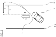
- the second controller 12 may control the steering device 106a to adjust the traveling direction of the subject vehicle 1 so that it stays inside the travel lane L. Specifically, when the direction of the subject vehicle 1 is not parallel to the direction of extension of the travel lane L as illustrated in FIG. 2 , the second controller 12 calculates a shortest time T1 required until the direction of the subject vehicle 1 becomes parallel to the direction of extension of the travel lane L.
- the second controller 12 calculates a lateral movement amount X of the subject vehicle 1 assuming that the direction of the subject vehicle 1 becomes parallel to the direction of extension of the travel lane L after the shortest time T 1 has elapsed.
- the lateral movement amount X is larger than a distance D between the current lateral position P of the vehicle and the lane boundary line B1 (X>D)
- the second controller 12 predicts that at least a part of the vehicle body of the subject vehicle 1 will deviate from the lane boundary line B1 of the travel lane L, and starts the deviation preventing control.
- the second controller 12 predicts that the subject vehicle 1 will not deviate from the travel lane L, and does not start the deviation preventing control.
- the second controller 12 acquires a steering speed limit value ⁇ ' of the subject vehicle 1.
- the second controller 12 obtains a steering angle change amount ⁇ (t) by integrating the steering speed limit value ⁇ ' over a time t and adds it to a current initial steering angle ⁇ (0) to create the following equation (1) which represents a steering angle ⁇ after the time t has elapsed.
- ⁇ ⁇ 0 + ⁇ t
- the second controller 12 generates, based on the vehicle speed V and vehicle body angle change amount ⁇ (t) of the subject vehicle 1, the following equation (3) which represents a lateral movement speed Vy(t) of the subject vehicle 1.
- Vy t V ⁇ sin ⁇ t
- the second controller 12 integrates the Vy(t) represented by the above equation (3) over the shortest time T1 to calculate the lateral movement amount X.
- the second controller 12 compares this lateral movement amount X with the distance D from the current lateral position P of the subject vehicle 1 to the lane boundary line B1 thereby to determine whether or not the subject vehicle 1 deviates from the travel lane L.
- the output device 105 may output hands-on request information that requests the driver to grasp the steering wheel 104a of the subject vehicle 1. After the control initiative has returned to the driver, the driving control device 100 may stop the driving assistance control which includes the lane keeping control and the deviation preventing control.
- the vehicle speed controller 13 illustrated in FIG. 1 controls the braking device 106b and the drive device 106c thereby to control the vehicle speed V and acceleration/deceleration of the subject vehicle 1.
- the first abnormality determiner 14a determines whether or not an abnormality occurs in the first controller 11 (whether or not the first controller 11 fails). Specifically, the first abnormality determiner 14a determines whether or not the second controller 12 starts the deviation preventing control during execution of the lane keeping control with the first controller 11. When the second controller 12 starts the deviation preventing control during execution of the lane keeping control, it is highly possible that the lane keeping control is not working properly, and the first abnormality determiner 14a therefore determines that an abnormality occurs in the first controller 11.
- an abnormality occurring means that a function to execute control fails.
- the first controller 11 determines that an abnormality occurs in the first controller 11 (the first controller 11 fails), that is, when the second controller 12 starts the deviation preventing control during execution of the lane keeping control, the first controller 11 concludes the lane keeping control.
- the processor 10 outputs an alarm including the hands-on request information to the output device 105.
- the vehicle speed controller 13 outputs control signals to the braking device 106b and the drive device 106c and starts deceleration control of the subject vehicle 1.
- the second controller 12 continues the deviation preventing control until the subject vehicle 1 decelerated by the deceleration control stops, and when the subject vehicle 1 stops, the second controller 12 concludes the deviation preventing control. If manual driving by the driver starts during the deceleration of the subject vehicle 1, the vehicle speed controller 13 will conclude the deceleration control before the subject vehicle 1 stops.
- the second abnormality determiner 14b is always determining whether or not an abnormality occurs in the second controller 12 (whether or not the second controller fails). That is, before the second controller 12 starts the deviation preventing control, the second abnormality determiner 14b determines whether or not an abnormality occurs in the second controller 12. When the second abnormality determiner 14b determines that an abnormality occurs in the second controller 12, the processor 10 of the driving control device 100 concludes the driving assistance control which includes the lane keeping control and the deviation preventing control. When detecting a system error of the second controller 12, the second abnormality determiner 14b determines that an abnormality occurs in the second controller 12.
- the second abnormality determiner 14b is determining whether a periodically calculated internal calculation result deviates from a reference value by a predetermined value or more. This predetermined value is appropriately set based on the experimental results, etc., depending on the system used.
- the second controller 12 performs the control so that the subject vehicle 1 does not deviate from the travel lane L, while the first controller 11 performs calculation so that the subject vehicle 1 travels along a route on the center of the lane during execution of the driving assistance control for the subject vehicle 1, so the number of internal calculations by the first controller 11 is large.
- the number of internal calculations in the first controller 11 is larger than that in the second controller 12, and the output values are generated by integrating these calculation results, so it is difficult for the first abnormality determiner 14a to determine a deviation in the internal calculation result of the first controller 11.
- each internal calculation may be different, and it is difficult for the first abnormality determiner 14a to accurately determine a deviation in the internal calculation result of the first controller 11.
- the driving control device 100 may control the subject vehicle 1 so as not to allow the driving assistance mode to transition to the hands-off mode.
- step S1 the second abnormality determiner 14b determines whether or not an abnormality occurs in the second controller 12.
- the driving control device 100 concludes the driving assistance control in step S8.
- Step S2 the first abnormality determiner 14a determines whether or not the second controller 12 starts the deviation preventing control during execution of the lane keeping control with the first controller 11.
- the second controller 12 does not start the deviation preventing control during execution of the lane keeping control with the first controller 11, the process is concluded.
- step S4 the first controller 11 concludes the lane keeping control.
- step S5 the vehicle speed controller 13 starts the deceleration control.
- step S4 and the process of step S5 may be performed simultaneously, or the process of step S4 may be performed after the process of step S5.
- the processor 10 of the driving control device 100 concludes the lane keeping control under execution, starts the deceleration control for the subject vehicle 1, continues the deviation preventing control until the subject vehicle 1 stops by the deceleration control, and concludes the deviation preventing control under execution when the subject vehicle stops by the deceleration control.
- the situation in which the second controller 12 starts the deviation preventing control during execution of the lane keeping control with the first controller 11 indicates that the subject vehicle 1 will deviate from the travel lane L or may possibly deviate from the travel lane L because the lane keeping control function of the first controller 11 is not fully exerted.
- the driving control device 100 determines whether or not the second controller 12 starts the deviation preventing control during execution of the lane keeping control with the first controller 11, thereby to determine a situation in which there is a possibility that an abnormality may occur in the execution function of the lane keeping control, and can control the driving of the subject vehicle in accordance with the determination result.
- the second controller 12 when starting the deviation preventing control during execution of the lane keeping control, that is, even when there is a possibility that an abnormality may occur in the execution function of the lane keeping control, the second controller 12 continues the deviation preventing control until the subject vehicle 1 stops, and concludes the deviation preventing control when the subject vehicle 1 stops.
- the driving control device 100 can stop the subject vehicle 1 while preventing the deviation of the subject vehicle 1 from the travel lane L and conclude the driving assistance control.
- the processor 10 of the driving control device 100 outputs the hands-on request information that requests the driver to grasp the steering wheel 104a of the subject vehicle 1. Through this operation, when an abnormality occurs in the function of executing the lane keeping control, the driver can grasp the steering wheel 104a to start the manual driving while the driving control device 100 is continuing the deviation preventing control.
Landscapes
- Engineering & Computer Science (AREA)
- Automation & Control Theory (AREA)
- Transportation (AREA)
- Mechanical Engineering (AREA)
- Human Computer Interaction (AREA)
- Steering Control In Accordance With Driving Conditions (AREA)
- Traffic Control Systems (AREA)
- Control Of Driving Devices And Active Controlling Of Vehicle (AREA)
Applications Claiming Priority (1)
| Application Number | Priority Date | Filing Date | Title |
|---|---|---|---|
| PCT/JP2021/041876 WO2023084767A1 (ja) | 2021-11-15 | 2021-11-15 | 運転制御方法及び運転制御装置 |
Publications (3)
| Publication Number | Publication Date |
|---|---|
| EP4434839A1 true EP4434839A1 (de) | 2024-09-25 |
| EP4434839A4 EP4434839A4 (de) | 2025-02-26 |
| EP4434839B1 EP4434839B1 (de) | 2025-07-09 |
Family
ID=86335455
Family Applications (1)
| Application Number | Title | Priority Date | Filing Date |
|---|---|---|---|
| EP21963480.5A Active EP4434839B1 (de) | 2021-11-15 | 2021-11-15 | Antriebssteuerungsverfahren und antriebssteuerungsvorrichtung |
Country Status (6)
| Country | Link |
|---|---|
| US (1) | US12275399B2 (de) |
| EP (1) | EP4434839B1 (de) |
| JP (1) | JP7616416B2 (de) |
| CN (1) | CN118234651B (de) |
| MX (1) | MX2024005686A (de) |
| WO (1) | WO2023084767A1 (de) |
Families Citing this family (1)
| Publication number | Priority date | Publication date | Assignee | Title |
|---|---|---|---|---|
| US12275399B2 (en) * | 2021-11-15 | 2025-04-15 | Nissan Motor Co., Ltd. | Driving control method and driving control device |
Family Cites Families (32)
| Publication number | Priority date | Publication date | Assignee | Title |
|---|---|---|---|---|
| JP3099675B2 (ja) * | 1995-04-06 | 2000-10-16 | トヨタ自動車株式会社 | 車両挙動制御システム |
| JP5359085B2 (ja) * | 2008-03-04 | 2013-12-04 | 日産自動車株式会社 | 車線維持支援装置及び車線維持支援方法 |
| US9542846B2 (en) * | 2011-02-28 | 2017-01-10 | GM Global Technology Operations LLC | Redundant lane sensing systems for fault-tolerant vehicular lateral controller |
| JP5924312B2 (ja) * | 2013-07-22 | 2016-05-25 | トヨタ自動車株式会社 | 車線維持支援装置 |
| KR101878690B1 (ko) * | 2013-08-05 | 2018-08-20 | 주식회사 만도 | 주차 동작 제어 장치 및 그 제어 방법 |
| JP6196518B2 (ja) | 2013-09-27 | 2017-09-13 | 株式会社Subaru | 運転支援装置 |
| JP5936281B2 (ja) * | 2014-03-31 | 2016-06-22 | 富士重工業株式会社 | 車両の車線逸脱防止制御装置 |
| JP2015209129A (ja) * | 2014-04-25 | 2015-11-24 | 富士重工業株式会社 | 車両の操舵制御装置 |
| KR102270287B1 (ko) * | 2014-11-19 | 2021-06-29 | 현대모비스 주식회사 | 차선 유지보조 시스템 및 방법 |
| JP6553917B2 (ja) * | 2015-03-31 | 2019-07-31 | アイシン・エィ・ダブリュ株式会社 | 自動運転支援システム、自動運転支援方法及びコンピュータプログラム |
| US10940868B2 (en) | 2015-07-10 | 2021-03-09 | Honda Motor Co., Ltd. | Vehicle control device, vehicle control method, and vehicle control program |
| JP6455456B2 (ja) * | 2016-02-16 | 2019-01-23 | トヨタ自動車株式会社 | 車両制御装置 |
| CN108698608B (zh) * | 2016-03-09 | 2021-11-12 | 本田技研工业株式会社 | 车辆控制系统、车辆控制方法及存储介质 |
| DE112017002524T5 (de) * | 2016-05-18 | 2019-01-31 | Advanced Smart Mobility Co., Ltd. | Fahrzeugantriebssteuersystem |
| JP6583183B2 (ja) * | 2016-08-04 | 2019-10-02 | トヨタ自動車株式会社 | 車両制御装置 |
| JP6536548B2 (ja) | 2016-12-01 | 2019-07-03 | トヨタ自動車株式会社 | 車線内走行支援装置 |
| EP3363698B1 (de) * | 2017-02-15 | 2021-05-26 | Volvo Car Corporation | Sicherheitsstoppvorrichtung und autonomes strassenfahrzeug damit |
| JP6601437B2 (ja) * | 2017-02-16 | 2019-11-06 | トヨタ自動車株式会社 | 車線逸脱抑制装置 |
| JP7000765B2 (ja) | 2017-09-19 | 2022-01-19 | スズキ株式会社 | 車両の走行制御装置 |
| WO2019094843A1 (en) * | 2017-11-10 | 2019-05-16 | Nvidia Corporation | Systems and methods for safe and reliable autonomous vehicles |
| JP2019111866A (ja) | 2017-12-21 | 2019-07-11 | トヨタ自動車株式会社 | 自動運転システム |
| JP7103071B2 (ja) * | 2018-08-30 | 2022-07-20 | トヨタ自動車株式会社 | 車両用電源システム |
| CN112969622A (zh) * | 2018-10-30 | 2021-06-15 | 动态Ad有限责任公司 | 自主运载工具中的冗余 |
| JP7165093B2 (ja) * | 2019-03-29 | 2022-11-02 | 本田技研工業株式会社 | 車両制御システム |
| FR3094317B1 (fr) * | 2019-04-01 | 2021-03-05 | Renault Sas | Module anticipateur, dispositif de contrôle en temps réel de trajectoire et procédé associés |
| US20210018921A1 (en) * | 2019-07-15 | 2021-01-21 | GM Global Technology Operations LLC | Method and system using novel software architecture of integrated motion controls |
| KR20210138201A (ko) * | 2020-05-11 | 2021-11-19 | 현대자동차주식회사 | 자율 주행 제어 방법 및 장치 |
| US11386776B2 (en) * | 2020-10-05 | 2022-07-12 | Qualcomm Incorporated | Managing a driving condition anomaly |
| JP7203884B2 (ja) * | 2021-03-31 | 2023-01-13 | 本田技研工業株式会社 | 車両制御装置、車両制御方法、およびプログラム |
| CN113525368A (zh) | 2021-06-23 | 2021-10-22 | 清华大学 | 车辆的车道保持紧急控制策略与安全控制方法及装置 |
| CN116209608A (zh) * | 2021-09-29 | 2023-06-02 | 华为技术有限公司 | 车辆控制的方法和装置 |
| US12275399B2 (en) * | 2021-11-15 | 2025-04-15 | Nissan Motor Co., Ltd. | Driving control method and driving control device |
-
2021
- 2021-11-15 US US18/709,746 patent/US12275399B2/en active Active
- 2021-11-15 CN CN202180104185.9A patent/CN118234651B/zh active Active
- 2021-11-15 MX MX2024005686A patent/MX2024005686A/es unknown
- 2021-11-15 JP JP2023559373A patent/JP7616416B2/ja active Active
- 2021-11-15 WO PCT/JP2021/041876 patent/WO2023084767A1/ja not_active Ceased
- 2021-11-15 EP EP21963480.5A patent/EP4434839B1/de active Active
Also Published As
| Publication number | Publication date |
|---|---|
| JP7616416B2 (ja) | 2025-01-17 |
| JPWO2023084767A1 (de) | 2023-05-19 |
| WO2023084767A1 (ja) | 2023-05-19 |
| CN118234651A (zh) | 2024-06-21 |
| MX2024005686A (es) | 2024-05-29 |
| EP4434839B1 (de) | 2025-07-09 |
| US20240425045A1 (en) | 2024-12-26 |
| EP4434839A4 (de) | 2025-02-26 |
| CN118234651B (zh) | 2025-06-27 |
| US12275399B2 (en) | 2025-04-15 |
Similar Documents
| Publication | Publication Date | Title |
|---|---|---|
| US12049252B2 (en) | Lane change assist apparatus for vehicle | |
| EP3418161B1 (de) | Lenkassistenzvorrichtung | |
| JP7508635B2 (ja) | 車両制御装置及び車両制御方法 | |
| US10795358B2 (en) | Automatic driving control device | |
| EP2982565B1 (de) | Fahrzeugsteuerungsvorrichtung | |
| US11180143B2 (en) | Vehicle control device | |
| EP1818231B1 (de) | Fahrzeugsteuerungssystem | |
| EP3306271A1 (de) | Fahrzeugstopppositioneinstellungsvorrichtung und -verfahren | |
| CN116653960A (zh) | 车辆控制装置 | |
| US11130488B2 (en) | Vehicle control device and vehicle control method | |
| US20230311875A1 (en) | Control device, method for operating control device, and non-transitory computer-readable storage medium | |
| US11285955B2 (en) | Vehicle control apparatus and vehicle with lane change regulation | |
| WO2016194168A1 (ja) | 走行制御装置及び方法 | |
| CN113428147B (zh) | 车辆控制装置及车辆控制方法 | |
| US11097729B2 (en) | Vehicle control device | |
| JP7138133B2 (ja) | 車両制御装置、車両、車両制御装置の動作方法およびプログラム | |
| EP4434839B1 (de) | Antriebssteuerungsverfahren und antriebssteuerungsvorrichtung | |
| JP2022157398A (ja) | 車両用制御装置および車両制御方法 | |
| JP7605332B2 (ja) | 運転制御方法及び運転制御装置 | |
| US12263858B2 (en) | Driving assistance device, vehicle, and driving assistance method | |
| EP4321405A1 (de) | Antriebssteuerungsverfahren für ein fahrzeug und antriebssteuerungsvorrichtung | |
| JP5018411B2 (ja) | 車両用追従装置 | |
| JP7740345B2 (ja) | 運転制御方法及び運転制御装置 | |
| US12447967B2 (en) | Vehicle control device, operation method of vehicle control device, and storage medium | |
| US20250263082A1 (en) | Driver state estimation apparatus |
Legal Events
| Date | Code | Title | Description |
|---|---|---|---|
| STAA | Information on the status of an ep patent application or granted ep patent |
Free format text: STATUS: THE INTERNATIONAL PUBLICATION HAS BEEN MADE |
|
| PUAI | Public reference made under article 153(3) epc to a published international application that has entered the european phase |
Free format text: ORIGINAL CODE: 0009012 |
|
| STAA | Information on the status of an ep patent application or granted ep patent |
Free format text: STATUS: REQUEST FOR EXAMINATION WAS MADE |
|
| 17P | Request for examination filed |
Effective date: 20240515 |
|
| AK | Designated contracting states |
Kind code of ref document: A1 Designated state(s): AL AT BE BG CH CY CZ DE DK EE ES FI FR GB GR HR HU IE IS IT LI LT LU LV MC MK MT NL NO PL PT RO RS SE SI SK SM TR |
|
| DAV | Request for validation of the european patent (deleted) | ||
| DAX | Request for extension of the european patent (deleted) | ||
| A4 | Supplementary search report drawn up and despatched |
Effective date: 20250128 |
|
| RIC1 | Information provided on ipc code assigned before grant |
Ipc: B60W 50/14 20200101ALI20250122BHEP Ipc: B60W 30/18 20120101ALI20250122BHEP Ipc: B60W 50/04 20060101ALI20250122BHEP Ipc: B60W 50/029 20120101ALI20250122BHEP Ipc: B60W 50/02 20120101ALI20250122BHEP Ipc: B60W 30/12 20200101AFI20250122BHEP |
|
| GRAP | Despatch of communication of intention to grant a patent |
Free format text: ORIGINAL CODE: EPIDOSNIGR1 |
|
| STAA | Information on the status of an ep patent application or granted ep patent |
Free format text: STATUS: GRANT OF PATENT IS INTENDED |
|
| INTG | Intention to grant announced |
Effective date: 20250404 |
|
| GRAS | Grant fee paid |
Free format text: ORIGINAL CODE: EPIDOSNIGR3 |
|
| GRAA | (expected) grant |
Free format text: ORIGINAL CODE: 0009210 |
|
| STAA | Information on the status of an ep patent application or granted ep patent |
Free format text: STATUS: THE PATENT HAS BEEN GRANTED |
|
| AK | Designated contracting states |
Kind code of ref document: B1 Designated state(s): AL AT BE BG CH CY CZ DE DK EE ES FI FR GB GR HR HU IE IS IT LI LT LU LV MC MK MT NL NO PL PT RO RS SE SI SK SM TR |
|
| REG | Reference to a national code |
Ref country code: GB Ref legal event code: FG4D |
|
| REG | Reference to a national code |
Ref country code: CH Ref legal event code: EP |
|
| REG | Reference to a national code |
Ref country code: IE Ref legal event code: FG4D |
|
| REG | Reference to a national code |
Ref country code: DE Ref legal event code: R096 Ref document number: 602021034018 Country of ref document: DE |
|
| REG | Reference to a national code |
Ref country code: NL Ref legal event code: MP Effective date: 20250709 |