EP4434770A2 - System und verfahren zur bayesschen inferenz bei der charakterisierung und vorhersage des verschleisses von fahrzeugreifen - Google Patents
System und verfahren zur bayesschen inferenz bei der charakterisierung und vorhersage des verschleisses von fahrzeugreifen Download PDFInfo
- Publication number
- EP4434770A2 EP4434770A2 EP24192375.4A EP24192375A EP4434770A2 EP 4434770 A2 EP4434770 A2 EP 4434770A2 EP 24192375 A EP24192375 A EP 24192375A EP 4434770 A2 EP4434770 A2 EP 4434770A2
- Authority
- EP
- European Patent Office
- Prior art keywords
- tire
- vehicle
- data
- wear
- tire wear
- Prior art date
- Legal status (The legal status is an assumption and is not a legal conclusion. Google has not performed a legal analysis and makes no representation as to the accuracy of the status listed.)
- Pending
Links
Images


Classifications
-
- B—PERFORMING OPERATIONS; TRANSPORTING
- B60—VEHICLES IN GENERAL
- B60W—CONJOINT CONTROL OF VEHICLE SUB-UNITS OF DIFFERENT TYPE OR DIFFERENT FUNCTION; CONTROL SYSTEMS SPECIALLY ADAPTED FOR HYBRID VEHICLES; ROAD VEHICLE DRIVE CONTROL SYSTEMS FOR PURPOSES NOT RELATED TO THE CONTROL OF A PARTICULAR SUB-UNIT
- B60W30/00—Purposes of road vehicle drive control systems not related to the control of a particular sub-unit, e.g. of systems using conjoint control of vehicle sub-units
- B60W30/14—Adaptive cruise control
- B60W30/143—Speed control
- B60W30/146—Speed limiting
-
- G—PHYSICS
- G06—COMPUTING OR CALCULATING; COUNTING
- G06F—ELECTRIC DIGITAL DATA PROCESSING
- G06F30/00—Computer-aided design [CAD]
- G06F30/10—Geometric CAD
- G06F30/15—Vehicle, aircraft or watercraft design
-
- B—PERFORMING OPERATIONS; TRANSPORTING
- B60—VEHICLES IN GENERAL
- B60C—VEHICLE TYRES; TYRE INFLATION; TYRE CHANGING; CONNECTING VALVES TO INFLATABLE ELASTIC BODIES IN GENERAL; DEVICES OR ARRANGEMENTS RELATED TO TYRES
- B60C11/00—Tyre tread bands; Tread patterns; Anti-skid inserts
- B60C11/24—Wear-indicating arrangements
- B60C11/243—Tread wear sensors, e.g. electronic sensors
-
- B—PERFORMING OPERATIONS; TRANSPORTING
- B60—VEHICLES IN GENERAL
- B60C—VEHICLE TYRES; TYRE INFLATION; TYRE CHANGING; CONNECTING VALVES TO INFLATABLE ELASTIC BODIES IN GENERAL; DEVICES OR ARRANGEMENTS RELATED TO TYRES
- B60C11/00—Tyre tread bands; Tread patterns; Anti-skid inserts
- B60C11/24—Wear-indicating arrangements
- B60C11/246—Tread wear monitoring systems
-
- B—PERFORMING OPERATIONS; TRANSPORTING
- B60—VEHICLES IN GENERAL
- B60C—VEHICLE TYRES; TYRE INFLATION; TYRE CHANGING; CONNECTING VALVES TO INFLATABLE ELASTIC BODIES IN GENERAL; DEVICES OR ARRANGEMENTS RELATED TO TYRES
- B60C23/00—Devices for measuring, signalling, controlling, or distributing tyre pressure or temperature, specially adapted for mounting on vehicles; Arrangement of tyre inflating devices on vehicles, e.g. of pumps or of tanks; Tyre cooling arrangements
- B60C23/02—Signalling devices actuated by tyre pressure
- B60C23/04—Signalling devices actuated by tyre pressure mounted on the wheel or tyre
- B60C23/0408—Signalling devices actuated by tyre pressure mounted on the wheel or tyre transmitting the signals by non-mechanical means from the wheel or tyre to a vehicle body mounted receiver
- B60C23/0479—Communicating with external units being not part of the vehicle, e.g. tools for diagnostic, mobile phones, electronic keys or service stations
-
- B—PERFORMING OPERATIONS; TRANSPORTING
- B60—VEHICLES IN GENERAL
- B60C—VEHICLE TYRES; TYRE INFLATION; TYRE CHANGING; CONNECTING VALVES TO INFLATABLE ELASTIC BODIES IN GENERAL; DEVICES OR ARRANGEMENTS RELATED TO TYRES
- B60C23/00—Devices for measuring, signalling, controlling, or distributing tyre pressure or temperature, specially adapted for mounting on vehicles; Arrangement of tyre inflating devices on vehicles, e.g. of pumps or of tanks; Tyre cooling arrangements
- B60C23/02—Signalling devices actuated by tyre pressure
- B60C23/04—Signalling devices actuated by tyre pressure mounted on the wheel or tyre
- B60C23/0486—Signalling devices actuated by tyre pressure mounted on the wheel or tyre comprising additional sensors in the wheel or tyre mounted monitoring device, e.g. movement sensors, microphones or earth magnetic field sensors
-
- B—PERFORMING OPERATIONS; TRANSPORTING
- B60—VEHICLES IN GENERAL
- B60C—VEHICLE TYRES; TYRE INFLATION; TYRE CHANGING; CONNECTING VALVES TO INFLATABLE ELASTIC BODIES IN GENERAL; DEVICES OR ARRANGEMENTS RELATED TO TYRES
- B60C23/00—Devices for measuring, signalling, controlling, or distributing tyre pressure or temperature, specially adapted for mounting on vehicles; Arrangement of tyre inflating devices on vehicles, e.g. of pumps or of tanks; Tyre cooling arrangements
- B60C23/06—Signalling devices actuated by deformation of the tyre, e.g. tyre mounted deformation sensors or indirect determination of tyre deformation based on wheel speed, wheel-centre to ground distance or inclination of wheel axle
- B60C23/061—Signalling devices actuated by deformation of the tyre, e.g. tyre mounted deformation sensors or indirect determination of tyre deformation based on wheel speed, wheel-centre to ground distance or inclination of wheel axle by monitoring wheel speed
- B60C23/062—Frequency spectrum analysis of wheel speed signals, e.g. using Fourier transformation
-
- B—PERFORMING OPERATIONS; TRANSPORTING
- B60—VEHICLES IN GENERAL
- B60C—VEHICLE TYRES; TYRE INFLATION; TYRE CHANGING; CONNECTING VALVES TO INFLATABLE ELASTIC BODIES IN GENERAL; DEVICES OR ARRANGEMENTS RELATED TO TYRES
- B60C99/00—Subject matter not provided for in other groups of this subclass
- B60C99/006—Computer aided tyre design or simulation
-
- B—PERFORMING OPERATIONS; TRANSPORTING
- B60—VEHICLES IN GENERAL
- B60T—VEHICLE BRAKE CONTROL SYSTEMS OR PARTS THEREOF; BRAKE CONTROL SYSTEMS OR PARTS THEREOF, IN GENERAL; ARRANGEMENT OF BRAKING ELEMENTS ON VEHICLES IN GENERAL; PORTABLE DEVICES FOR PREVENTING UNWANTED MOVEMENT OF VEHICLES; VEHICLE MODIFICATIONS TO FACILITATE COOLING OF BRAKES
- B60T7/00—Brake-action initiating means
- B60T7/12—Brake-action initiating means for automatic initiation; for initiation not subject to will of driver or passenger
-
- B—PERFORMING OPERATIONS; TRANSPORTING
- B60—VEHICLES IN GENERAL
- B60T—VEHICLE BRAKE CONTROL SYSTEMS OR PARTS THEREOF; BRAKE CONTROL SYSTEMS OR PARTS THEREOF, IN GENERAL; ARRANGEMENT OF BRAKING ELEMENTS ON VEHICLES IN GENERAL; PORTABLE DEVICES FOR PREVENTING UNWANTED MOVEMENT OF VEHICLES; VEHICLE MODIFICATIONS TO FACILITATE COOLING OF BRAKES
- B60T8/00—Arrangements for adjusting wheel-braking force to meet varying vehicular or ground-surface conditions, e.g. limiting or varying distribution of braking force
- B60T8/17—Using electrical or electronic regulation means to control braking
- B60T8/171—Detecting parameters used in the regulation; Measuring values used in the regulation
-
- B—PERFORMING OPERATIONS; TRANSPORTING
- B60—VEHICLES IN GENERAL
- B60W—CONJOINT CONTROL OF VEHICLE SUB-UNITS OF DIFFERENT TYPE OR DIFFERENT FUNCTION; CONTROL SYSTEMS SPECIALLY ADAPTED FOR HYBRID VEHICLES; ROAD VEHICLE DRIVE CONTROL SYSTEMS FOR PURPOSES NOT RELATED TO THE CONTROL OF A PARTICULAR SUB-UNIT
- B60W30/00—Purposes of road vehicle drive control systems not related to the control of a particular sub-unit, e.g. of systems using conjoint control of vehicle sub-units
- B60W30/14—Adaptive cruise control
- B60W30/16—Control of distance between vehicles, e.g. keeping a distance to preceding vehicle
- B60W30/162—Speed limiting therefor
-
- B—PERFORMING OPERATIONS; TRANSPORTING
- B60—VEHICLES IN GENERAL
- B60W—CONJOINT CONTROL OF VEHICLE SUB-UNITS OF DIFFERENT TYPE OR DIFFERENT FUNCTION; CONTROL SYSTEMS SPECIALLY ADAPTED FOR HYBRID VEHICLES; ROAD VEHICLE DRIVE CONTROL SYSTEMS FOR PURPOSES NOT RELATED TO THE CONTROL OF A PARTICULAR SUB-UNIT
- B60W40/00—Estimation or calculation of non-directly measurable driving parameters for road vehicle drive control systems not related to the control of a particular sub unit, e.g. by using mathematical models
- B60W40/02—Estimation or calculation of non-directly measurable driving parameters for road vehicle drive control systems not related to the control of a particular sub unit, e.g. by using mathematical models related to ambient conditions
- B60W40/06—Road conditions
- B60W40/064—Degree of grip
-
- B—PERFORMING OPERATIONS; TRANSPORTING
- B60—VEHICLES IN GENERAL
- B60W—CONJOINT CONTROL OF VEHICLE SUB-UNITS OF DIFFERENT TYPE OR DIFFERENT FUNCTION; CONTROL SYSTEMS SPECIALLY ADAPTED FOR HYBRID VEHICLES; ROAD VEHICLE DRIVE CONTROL SYSTEMS FOR PURPOSES NOT RELATED TO THE CONTROL OF A PARTICULAR SUB-UNIT
- B60W40/00—Estimation or calculation of non-directly measurable driving parameters for road vehicle drive control systems not related to the control of a particular sub unit, e.g. by using mathematical models
- B60W40/12—Estimation or calculation of non-directly measurable driving parameters for road vehicle drive control systems not related to the control of a particular sub unit, e.g. by using mathematical models related to parameters of the vehicle itself, e.g. tyre models
-
- B—PERFORMING OPERATIONS; TRANSPORTING
- B60—VEHICLES IN GENERAL
- B60W—CONJOINT CONTROL OF VEHICLE SUB-UNITS OF DIFFERENT TYPE OR DIFFERENT FUNCTION; CONTROL SYSTEMS SPECIALLY ADAPTED FOR HYBRID VEHICLES; ROAD VEHICLE DRIVE CONTROL SYSTEMS FOR PURPOSES NOT RELATED TO THE CONTROL OF A PARTICULAR SUB-UNIT
- B60W50/00—Details of control systems for road vehicle drive control not related to the control of a particular sub-unit, e.g. process diagnostic or vehicle driver interfaces
- B60W50/08—Interaction between the driver and the control system
- B60W50/14—Means for informing the driver, warning the driver or prompting a driver intervention
-
- G—PHYSICS
- G01—MEASURING; TESTING
- G01M—TESTING STATIC OR DYNAMIC BALANCE OF MACHINES OR STRUCTURES; TESTING OF STRUCTURES OR APPARATUS, NOT OTHERWISE PROVIDED FOR
- G01M17/00—Testing of vehicles
- G01M17/007—Wheeled or endless-tracked vehicles
- G01M17/02—Tyres
-
- G—PHYSICS
- G06—COMPUTING OR CALCULATING; COUNTING
- G06F—ELECTRIC DIGITAL DATA PROCESSING
- G06F17/00—Digital computing or data processing equipment or methods, specially adapted for specific functions
- G06F17/10—Complex mathematical operations
- G06F17/14—Fourier, Walsh or analogous domain transformations, e.g. Laplace, Hilbert, Karhunen-Loeve, transforms
- G06F17/141—Discrete Fourier transforms
- G06F17/142—Fast Fourier transforms, e.g. using a Cooley-Tukey type algorithm
-
- G—PHYSICS
- G06—COMPUTING OR CALCULATING; COUNTING
- G06F—ELECTRIC DIGITAL DATA PROCESSING
- G06F30/00—Computer-aided design [CAD]
- G06F30/20—Design optimisation, verification or simulation
-
- G—PHYSICS
- G06—COMPUTING OR CALCULATING; COUNTING
- G06N—COMPUTING ARRANGEMENTS BASED ON SPECIFIC COMPUTATIONAL MODELS
- G06N3/00—Computing arrangements based on biological models
- G06N3/02—Neural networks
- G06N3/04—Architecture, e.g. interconnection topology
- G06N3/045—Combinations of networks
-
- G—PHYSICS
- G06—COMPUTING OR CALCULATING; COUNTING
- G06N—COMPUTING ARRANGEMENTS BASED ON SPECIFIC COMPUTATIONAL MODELS
- G06N3/00—Computing arrangements based on biological models
- G06N3/02—Neural networks
- G06N3/08—Learning methods
- G06N3/084—Backpropagation, e.g. using gradient descent
-
- G—PHYSICS
- G06—COMPUTING OR CALCULATING; COUNTING
- G06N—COMPUTING ARRANGEMENTS BASED ON SPECIFIC COMPUTATIONAL MODELS
- G06N7/00—Computing arrangements based on specific mathematical models
- G06N7/01—Probabilistic graphical models, e.g. probabilistic networks
-
- G—PHYSICS
- G06—COMPUTING OR CALCULATING; COUNTING
- G06Q—INFORMATION AND COMMUNICATION TECHNOLOGY [ICT] SPECIALLY ADAPTED FOR ADMINISTRATIVE, COMMERCIAL, FINANCIAL, MANAGERIAL OR SUPERVISORY PURPOSES; SYSTEMS OR METHODS SPECIALLY ADAPTED FOR ADMINISTRATIVE, COMMERCIAL, FINANCIAL, MANAGERIAL OR SUPERVISORY PURPOSES, NOT OTHERWISE PROVIDED FOR
- G06Q10/00—Administration; Management
- G06Q10/20—Administration of product repair or maintenance
-
- G—PHYSICS
- G07—CHECKING-DEVICES
- G07C—TIME OR ATTENDANCE REGISTERS; REGISTERING OR INDICATING THE WORKING OF MACHINES; GENERATING RANDOM NUMBERS; VOTING OR LOTTERY APPARATUS; ARRANGEMENTS, SYSTEMS OR APPARATUS FOR CHECKING NOT PROVIDED FOR ELSEWHERE
- G07C5/00—Registering or indicating the working of vehicles
- G07C5/006—Indicating maintenance
-
- G—PHYSICS
- G07—CHECKING-DEVICES
- G07C—TIME OR ATTENDANCE REGISTERS; REGISTERING OR INDICATING THE WORKING OF MACHINES; GENERATING RANDOM NUMBERS; VOTING OR LOTTERY APPARATUS; ARRANGEMENTS, SYSTEMS OR APPARATUS FOR CHECKING NOT PROVIDED FOR ELSEWHERE
- G07C5/00—Registering or indicating the working of vehicles
- G07C5/008—Registering or indicating the working of vehicles communicating information to a remotely located station
-
- G—PHYSICS
- G07—CHECKING-DEVICES
- G07C—TIME OR ATTENDANCE REGISTERS; REGISTERING OR INDICATING THE WORKING OF MACHINES; GENERATING RANDOM NUMBERS; VOTING OR LOTTERY APPARATUS; ARRANGEMENTS, SYSTEMS OR APPARATUS FOR CHECKING NOT PROVIDED FOR ELSEWHERE
- G07C5/00—Registering or indicating the working of vehicles
- G07C5/02—Registering or indicating driving, working, idle, or waiting time only
- G07C5/04—Registering or indicating driving, working, idle, or waiting time only using counting means or digital clocks
-
- G—PHYSICS
- G07—CHECKING-DEVICES
- G07C—TIME OR ATTENDANCE REGISTERS; REGISTERING OR INDICATING THE WORKING OF MACHINES; GENERATING RANDOM NUMBERS; VOTING OR LOTTERY APPARATUS; ARRANGEMENTS, SYSTEMS OR APPARATUS FOR CHECKING NOT PROVIDED FOR ELSEWHERE
- G07C5/00—Registering or indicating the working of vehicles
- G07C5/08—Registering or indicating performance data other than driving, working, idle, or waiting time, with or without registering driving, working, idle or waiting time
- G07C5/0808—Diagnosing performance data
-
- G—PHYSICS
- G08—SIGNALLING
- G08G—TRAFFIC CONTROL SYSTEMS
- G08G1/00—Traffic control systems for road vehicles
- G08G1/22—Platooning, i.e. convoy of communicating vehicles
-
- H—ELECTRICITY
- H04—ELECTRIC COMMUNICATION TECHNIQUE
- H04L—TRANSMISSION OF DIGITAL INFORMATION, e.g. TELEGRAPHIC COMMUNICATION
- H04L12/00—Data switching networks
- H04L12/28—Data switching networks characterised by path configuration, e.g. LAN [Local Area Networks] or WAN [Wide Area Networks]
- H04L12/40—Bus networks
- H04L12/40006—Architecture of a communication node
- H04L12/40013—Details regarding a bus controller
-
- H—ELECTRICITY
- H04—ELECTRIC COMMUNICATION TECHNIQUE
- H04W—WIRELESS COMMUNICATION NETWORKS
- H04W4/00—Services specially adapted for wireless communication networks; Facilities therefor
- H04W4/30—Services specially adapted for particular environments, situations or purposes
- H04W4/40—Services specially adapted for particular environments, situations or purposes for vehicles, e.g. vehicle-to-pedestrians [V2P]
- H04W4/44—Services specially adapted for particular environments, situations or purposes for vehicles, e.g. vehicle-to-pedestrians [V2P] for communication between vehicles and infrastructures, e.g. vehicle-to-cloud [V2C] or vehicle-to-home [V2H]
-
- B—PERFORMING OPERATIONS; TRANSPORTING
- B60—VEHICLES IN GENERAL
- B60C—VEHICLE TYRES; TYRE INFLATION; TYRE CHANGING; CONNECTING VALVES TO INFLATABLE ELASTIC BODIES IN GENERAL; DEVICES OR ARRANGEMENTS RELATED TO TYRES
- B60C19/00—Tyre parts or constructions not otherwise provided for
- B60C2019/004—Tyre sensors other than for detecting tyre pressure
-
- B—PERFORMING OPERATIONS; TRANSPORTING
- B60—VEHICLES IN GENERAL
- B60C—VEHICLE TYRES; TYRE INFLATION; TYRE CHANGING; CONNECTING VALVES TO INFLATABLE ELASTIC BODIES IN GENERAL; DEVICES OR ARRANGEMENTS RELATED TO TYRES
- B60C23/00—Devices for measuring, signalling, controlling, or distributing tyre pressure or temperature, specially adapted for mounting on vehicles; Arrangement of tyre inflating devices on vehicles, e.g. of pumps or of tanks; Tyre cooling arrangements
- B60C23/02—Signalling devices actuated by tyre pressure
- B60C23/04—Signalling devices actuated by tyre pressure mounted on the wheel or tyre
- B60C23/0408—Signalling devices actuated by tyre pressure mounted on the wheel or tyre transmitting the signals by non-mechanical means from the wheel or tyre to a vehicle body mounted receiver
- B60C23/0415—Automatically identifying wheel mounted units, e.g. after replacement or exchange of wheels
-
- B—PERFORMING OPERATIONS; TRANSPORTING
- B60—VEHICLES IN GENERAL
- B60T—VEHICLE BRAKE CONTROL SYSTEMS OR PARTS THEREOF; BRAKE CONTROL SYSTEMS OR PARTS THEREOF, IN GENERAL; ARRANGEMENT OF BRAKING ELEMENTS ON VEHICLES IN GENERAL; PORTABLE DEVICES FOR PREVENTING UNWANTED MOVEMENT OF VEHICLES; VEHICLE MODIFICATIONS TO FACILITATE COOLING OF BRAKES
- B60T2201/00—Particular use of vehicle brake systems; Special systems using also the brakes; Special software modules within the brake system controller
- B60T2201/03—Brake assistants
-
- B—PERFORMING OPERATIONS; TRANSPORTING
- B60—VEHICLES IN GENERAL
- B60T—VEHICLE BRAKE CONTROL SYSTEMS OR PARTS THEREOF; BRAKE CONTROL SYSTEMS OR PARTS THEREOF, IN GENERAL; ARRANGEMENT OF BRAKING ELEMENTS ON VEHICLES IN GENERAL; PORTABLE DEVICES FOR PREVENTING UNWANTED MOVEMENT OF VEHICLES; VEHICLE MODIFICATIONS TO FACILITATE COOLING OF BRAKES
- B60T2210/00—Detection or estimation of road or environment conditions; Detection or estimation of road shapes
- B60T2210/30—Environment conditions or position therewithin
-
- B—PERFORMING OPERATIONS; TRANSPORTING
- B60—VEHICLES IN GENERAL
- B60T—VEHICLE BRAKE CONTROL SYSTEMS OR PARTS THEREOF; BRAKE CONTROL SYSTEMS OR PARTS THEREOF, IN GENERAL; ARRANGEMENT OF BRAKING ELEMENTS ON VEHICLES IN GENERAL; PORTABLE DEVICES FOR PREVENTING UNWANTED MOVEMENT OF VEHICLES; VEHICLE MODIFICATIONS TO FACILITATE COOLING OF BRAKES
- B60T2240/00—Monitoring, detecting wheel/tyre behaviour; counteracting thereof
- B60T2240/02—Longitudinal grip
-
- B—PERFORMING OPERATIONS; TRANSPORTING
- B60—VEHICLES IN GENERAL
- B60T—VEHICLE BRAKE CONTROL SYSTEMS OR PARTS THEREOF; BRAKE CONTROL SYSTEMS OR PARTS THEREOF, IN GENERAL; ARRANGEMENT OF BRAKING ELEMENTS ON VEHICLES IN GENERAL; PORTABLE DEVICES FOR PREVENTING UNWANTED MOVEMENT OF VEHICLES; VEHICLE MODIFICATIONS TO FACILITATE COOLING OF BRAKES
- B60T2240/00—Monitoring, detecting wheel/tyre behaviour; counteracting thereof
- B60T2240/03—Tyre sensors
-
- B—PERFORMING OPERATIONS; TRANSPORTING
- B60—VEHICLES IN GENERAL
- B60W—CONJOINT CONTROL OF VEHICLE SUB-UNITS OF DIFFERENT TYPE OR DIFFERENT FUNCTION; CONTROL SYSTEMS SPECIALLY ADAPTED FOR HYBRID VEHICLES; ROAD VEHICLE DRIVE CONTROL SYSTEMS FOR PURPOSES NOT RELATED TO THE CONTROL OF A PARTICULAR SUB-UNIT
- B60W40/00—Estimation or calculation of non-directly measurable driving parameters for road vehicle drive control systems not related to the control of a particular sub unit, e.g. by using mathematical models
- B60W40/12—Estimation or calculation of non-directly measurable driving parameters for road vehicle drive control systems not related to the control of a particular sub unit, e.g. by using mathematical models related to parameters of the vehicle itself, e.g. tyre models
- B60W40/13—Load or weight
- B60W2040/1392—Natural frequency of components
-
- B—PERFORMING OPERATIONS; TRANSPORTING
- B60—VEHICLES IN GENERAL
- B60W—CONJOINT CONTROL OF VEHICLE SUB-UNITS OF DIFFERENT TYPE OR DIFFERENT FUNCTION; CONTROL SYSTEMS SPECIALLY ADAPTED FOR HYBRID VEHICLES; ROAD VEHICLE DRIVE CONTROL SYSTEMS FOR PURPOSES NOT RELATED TO THE CONTROL OF A PARTICULAR SUB-UNIT
- B60W50/00—Details of control systems for road vehicle drive control not related to the control of a particular sub-unit, e.g. process diagnostic or vehicle driver interfaces
- B60W50/08—Interaction between the driver and the control system
- B60W50/14—Means for informing the driver, warning the driver or prompting a driver intervention
- B60W2050/146—Display means
-
- B—PERFORMING OPERATIONS; TRANSPORTING
- B60—VEHICLES IN GENERAL
- B60W—CONJOINT CONTROL OF VEHICLE SUB-UNITS OF DIFFERENT TYPE OR DIFFERENT FUNCTION; CONTROL SYSTEMS SPECIALLY ADAPTED FOR HYBRID VEHICLES; ROAD VEHICLE DRIVE CONTROL SYSTEMS FOR PURPOSES NOT RELATED TO THE CONTROL OF A PARTICULAR SUB-UNIT
- B60W2420/00—Indexing codes relating to the type of sensors based on the principle of their operation
- B60W2420/90—Single sensor for two or more measurements
- B60W2420/905—Single sensor for two or more measurements the sensor being an xyz axis sensor
-
- B—PERFORMING OPERATIONS; TRANSPORTING
- B60—VEHICLES IN GENERAL
- B60W—CONJOINT CONTROL OF VEHICLE SUB-UNITS OF DIFFERENT TYPE OR DIFFERENT FUNCTION; CONTROL SYSTEMS SPECIALLY ADAPTED FOR HYBRID VEHICLES; ROAD VEHICLE DRIVE CONTROL SYSTEMS FOR PURPOSES NOT RELATED TO THE CONTROL OF A PARTICULAR SUB-UNIT
- B60W2520/00—Input parameters relating to overall vehicle dynamics
- B60W2520/10—Longitudinal speed
- B60W2520/105—Longitudinal acceleration
-
- B—PERFORMING OPERATIONS; TRANSPORTING
- B60—VEHICLES IN GENERAL
- B60W—CONJOINT CONTROL OF VEHICLE SUB-UNITS OF DIFFERENT TYPE OR DIFFERENT FUNCTION; CONTROL SYSTEMS SPECIALLY ADAPTED FOR HYBRID VEHICLES; ROAD VEHICLE DRIVE CONTROL SYSTEMS FOR PURPOSES NOT RELATED TO THE CONTROL OF A PARTICULAR SUB-UNIT
- B60W2520/00—Input parameters relating to overall vehicle dynamics
- B60W2520/12—Lateral speed
- B60W2520/125—Lateral acceleration
-
- B—PERFORMING OPERATIONS; TRANSPORTING
- B60—VEHICLES IN GENERAL
- B60W—CONJOINT CONTROL OF VEHICLE SUB-UNITS OF DIFFERENT TYPE OR DIFFERENT FUNCTION; CONTROL SYSTEMS SPECIALLY ADAPTED FOR HYBRID VEHICLES; ROAD VEHICLE DRIVE CONTROL SYSTEMS FOR PURPOSES NOT RELATED TO THE CONTROL OF A PARTICULAR SUB-UNIT
- B60W2530/00—Input parameters relating to vehicle conditions or values, not covered by groups B60W2510/00 or B60W2520/00
- B60W2530/20—Tyre data
-
- B—PERFORMING OPERATIONS; TRANSPORTING
- B60—VEHICLES IN GENERAL
- B60W—CONJOINT CONTROL OF VEHICLE SUB-UNITS OF DIFFERENT TYPE OR DIFFERENT FUNCTION; CONTROL SYSTEMS SPECIALLY ADAPTED FOR HYBRID VEHICLES; ROAD VEHICLE DRIVE CONTROL SYSTEMS FOR PURPOSES NOT RELATED TO THE CONTROL OF A PARTICULAR SUB-UNIT
- B60W2555/00—Input parameters relating to exterior conditions, not covered by groups B60W2552/00, B60W2554/00
-
- B—PERFORMING OPERATIONS; TRANSPORTING
- B60—VEHICLES IN GENERAL
- B60W—CONJOINT CONTROL OF VEHICLE SUB-UNITS OF DIFFERENT TYPE OR DIFFERENT FUNCTION; CONTROL SYSTEMS SPECIALLY ADAPTED FOR HYBRID VEHICLES; ROAD VEHICLE DRIVE CONTROL SYSTEMS FOR PURPOSES NOT RELATED TO THE CONTROL OF A PARTICULAR SUB-UNIT
- B60W2556/00—Input parameters relating to data
- B60W2556/10—Historical data
-
- B—PERFORMING OPERATIONS; TRANSPORTING
- B60—VEHICLES IN GENERAL
- B60W—CONJOINT CONTROL OF VEHICLE SUB-UNITS OF DIFFERENT TYPE OR DIFFERENT FUNCTION; CONTROL SYSTEMS SPECIALLY ADAPTED FOR HYBRID VEHICLES; ROAD VEHICLE DRIVE CONTROL SYSTEMS FOR PURPOSES NOT RELATED TO THE CONTROL OF A PARTICULAR SUB-UNIT
- B60W2556/00—Input parameters relating to data
- B60W2556/45—External transmission of data to or from the vehicle
-
- B—PERFORMING OPERATIONS; TRANSPORTING
- B60—VEHICLES IN GENERAL
- B60W—CONJOINT CONTROL OF VEHICLE SUB-UNITS OF DIFFERENT TYPE OR DIFFERENT FUNCTION; CONTROL SYSTEMS SPECIALLY ADAPTED FOR HYBRID VEHICLES; ROAD VEHICLE DRIVE CONTROL SYSTEMS FOR PURPOSES NOT RELATED TO THE CONTROL OF A PARTICULAR SUB-UNIT
- B60W2756/00—Output or target parameters relating to data
- B60W2756/10—Involving external transmission of data to or from the vehicle
-
- B—PERFORMING OPERATIONS; TRANSPORTING
- B60—VEHICLES IN GENERAL
- B60W—CONJOINT CONTROL OF VEHICLE SUB-UNITS OF DIFFERENT TYPE OR DIFFERENT FUNCTION; CONTROL SYSTEMS SPECIALLY ADAPTED FOR HYBRID VEHICLES; ROAD VEHICLE DRIVE CONTROL SYSTEMS FOR PURPOSES NOT RELATED TO THE CONTROL OF A PARTICULAR SUB-UNIT
- B60W30/00—Purposes of road vehicle drive control systems not related to the control of a particular sub-unit, e.g. of systems using conjoint control of vehicle sub-units
- B60W30/18—Propelling the vehicle
- B60W30/18172—Preventing, or responsive to skidding of wheels
-
- G—PHYSICS
- G07—CHECKING-DEVICES
- G07C—TIME OR ATTENDANCE REGISTERS; REGISTERING OR INDICATING THE WORKING OF MACHINES; GENERATING RANDOM NUMBERS; VOTING OR LOTTERY APPARATUS; ARRANGEMENTS, SYSTEMS OR APPARATUS FOR CHECKING NOT PROVIDED FOR ELSEWHERE
- G07C5/00—Registering or indicating the working of vehicles
- G07C5/08—Registering or indicating performance data other than driving, working, idle, or waiting time, with or without registering driving, working, idle or waiting time
- G07C5/0841—Registering performance data
-
- H—ELECTRICITY
- H04—ELECTRIC COMMUNICATION TECHNIQUE
- H04L—TRANSMISSION OF DIGITAL INFORMATION, e.g. TELEGRAPHIC COMMUNICATION
- H04L12/00—Data switching networks
- H04L12/28—Data switching networks characterised by path configuration, e.g. LAN [Local Area Networks] or WAN [Wide Area Networks]
- H04L12/40—Bus networks
- H04L2012/40208—Bus networks characterized by the use of a particular bus standard
- H04L2012/40215—Controller Area Network CAN
-
- H—ELECTRICITY
- H04—ELECTRIC COMMUNICATION TECHNIQUE
- H04L—TRANSMISSION OF DIGITAL INFORMATION, e.g. TELEGRAPHIC COMMUNICATION
- H04L12/00—Data switching networks
- H04L12/28—Data switching networks characterised by path configuration, e.g. LAN [Local Area Networks] or WAN [Wide Area Networks]
- H04L12/40—Bus networks
- H04L2012/40267—Bus for use in transportation systems
- H04L2012/40273—Bus for use in transportation systems the transportation system being a vehicle
Definitions
- the present invention relates generally to the modeling and predicting of tire performance and the provision of feedback based thereon. More particularly, an embodiment of an invention as disclosed herein relates to systems and methods for implementing tire wear and/or tire traction models for wheeled vehicles including but not limited to motorcycles, consumer vehicles (e.g., passenger and light truck), commercial and off-road (OTR) vehicles.
- wheeled vehicles including but not limited to motorcycles, consumer vehicles (e.g., passenger and light truck), commercial and off-road (OTR) vehicles.
- irregular tread wear may occur for a variety of reasons that may lead users to replace a tire sooner than would otherwise have been necessary.
- Vehicles, drivers, and individual tires are all different from each other, and can cause tires to wear at very different rates. For instance, high performance tires for sports cars wear more quickly than touring tires for a family sedan.
- a wide variety of factors can cause a tire to wear out sooner than expected, and/or cause it to wear irregularly and create noise or vibration.
- Two common causes of premature and/or irregular tire wear are improper inflation pressure and out-of-spec alignment conditions.
- Tire wear is known to progress in a non-linear fashion throughout the life of a tire.
- One primary reason for this is that as the tread wears over time, the tread blocks become stiffer.
- the tread patterns are typically designed to have less void area as the tire wears. Either or both of these characteristics can contribute to a slower wear rate.
- the focus of most tire wear predictions is on the initial wear rate - the wear rate when the tire is brand new. This is at least in part because the tire industry is typically concerned with new tire performance in general, due to having to meet original equipment manufacturer (OEM) requirements. To predict the performance of a tire for the entirety of its life, a new wear model is required.
- OEM original equipment manufacturer
- tread depth prediction is the first step to predicting numerous other tire performance areas.
- the aforementioned objects may be attained via a computer-implemented method for modeling and predicting of tire performance and the provision of feedback based thereon.
- the method includes collecting vehicle data for a vehicle and/or tire data for at least one tire associated with the vehicle, and determining a current tire wear status in real-time for the at least one tire, based at least in part on the collected data.
- One or more tire performance characteristics are predicted, based at least in part on the determined tire wear status and the collected data.
- Real-time feedback is selectively provided, based on the predicted one or more tire performance characteristics and/or determined current tire wear status.
- a second embodiment of the computer-implemented method for estimating a tire wear status, and comprises accumulating in data storage information regarding probability distributions corresponding to each of a respective plurality of tire wear factors.
- Vehicle data and/or tire data comprising movement data and location data collected in association with a vehicle is transmitted from the vehicle to a remote server.
- At least one observation corresponding to one or more of the plurality of factors is generated based on the transmitted vehicle data.
- a Bayesian estimation of a tire wear status at a given time is generated for at least one tire associated with the vehicle, based at least on the at least one generated observation and the stored information regarding probability distributions.
- One exemplary aspect of the aforementioned second embodiment may include storing information regarding updated probability distributions corresponding to a respective plurality of factors contributing to tire wear for the at least one tire associated with the vehicle, based at least on the generated at least one observation.
- Another exemplary aspect of the aforementioned second embodiment may include predicting a tire wear status at one or more future parameters for the at least one tire associated with the vehicle.
- the tire wear status may be predicted with respect to an upcoming period of time that the vehicle is driven, or with respect to an upcoming distance to be traveled.
- Another exemplary aspect of the aforementioned second embodiment may include predicting a replacement time for the at least one tire associated with the vehicle, based on a current tire wear status or the predicted tire wear status as compared with tire wear thresholds associated with the at least one tire associated with the vehicle.
- the information regarding the plurality of probability distributions may reflect an array of time-series characterization curves.
- Another exemplary aspect of the aforementioned second embodiment may include receiving one or more tire wear input values from a user via a user interface associated with the remote server and generating at least one observation for one or more of the plurality of factors based on the one or more tire wear input values.
- Another exemplary aspect of the aforementioned second embodiment may include receiving one or more tire wear input values generated by one or more sensors mounted in or on a respective tire of the at least one tire and generating at least one observation for one or more of the plurality of factors based on the one or more tire wear input values.
- Another exemplary aspect of the aforementioned second embodiment may include receiving one or more tire wear input values generated by a sensor external to the vehicle and generating at least one observation for one or more of the plurality of factors based on the one or more tire wear input values.
- At least one of the tire wear input values generated by the sensor external to the vehicle comprises a tread depth measurement.
- Another exemplary aspect of the aforementioned second embodiment may include generating an estimated tire wear status with a baseline value and a range corresponding to a confidence level for the estimation.
- a system may be provided in accordance with the above-referenced second embodiment to estimate a tire wear status.
- the system may include a data storage network having stored thereon information regarding probability distributions corresponding to each of a respective plurality of tire wear factors.
- distributed computing nodes are linked to one or more vehicle-mounted sensors respectively configured to collect vehicle data.
- a server-based computing network is provided comprising computer readable media having instructions residing thereon and executable by one or more processors to direct the performance of aspects previously recited with respect to the second embodiment.
- a third embodiment of the computer-implemented method is disclosed herein for an analytical tire wear model utilizing a brush-type model.
- the brush-type model is a simplified tire model that models the tread elements as independent "brush bristles" which greatly reduces the complexity of modeling the contact interface between the road and rubber. This model can capture the first order effects (tread block stiffening and contact area increasing) that occurs in a real tire as it wears.
- an original tread depth is determined for a tire associated with a vehicle, and an initial wear rate is determined for the tire based at least partially on the original tread depth.
- One or more tire conditions are measured as time-series inputs to a predictive tire wear model.
- a current wear rate is normalized based on said inputs with respect to the initial wear rate for the tire, wherein a tire wear status of the tire can be predicted for one or more specified future parameters.
- the current wear rate is further determined at least in part based on a brush-type tire wear model for a contact interface between a base material of the tire and a road surface, wherein the interface is represented as a plurality of independently deformable elements.
- the measured one or more tire conditions comprise detected contact areas and void areas corresponding to tire tread depths.
- the one or more specified future parameters are associated with a time traveled.
- the one or more specified future parameters may be associated with a distance traveled.
- a replacement time for the tire may be predicted based on the predicted tire wear status as compared with one or more predetermined tire wear thresholds associated with the tire.
- an alert is generated to a user associated with the vehicle based on the predicted replacement time.
- one or more measured conditions are received from a user via a user interface.
- one or more of the measured conditions are generated by one or more sensors mounted in or on the tire and received therefrom.
- one or more measured conditions are generated by a sensor external to the vehicle and received therefrom.
- At least one of the tire wear input values generated by the sensor external to the vehicle may comprise a tread depth measurement.
- a tire rotation threshold event and/or an alignment threshold event may be predicted by the system based at least partially on the time-series inputs and/or the predicted tire wear status.
- An alert may accordingly be generated to a user interface associated with the vehicle based thereon.
- the user interface may be a static display mounted in the vehicle, a display for a mobile computing device associated with a driver of the vehicle, etc.
- an optimal type of tire for the vehicle may be predicted based at least in part on the time-series inputs and/or the predicted tire wear status.
- An alert may accordingly be generated to a user interface associated with the vehicle based thereon.
- the user interface may be a static display mounted in the vehicle, a display for a mobile computing device associated with a driver of the vehicle, etc.
- a system may be provided for predicting progression in vehicle tire wear in accordance with the aforementioned third embodiment, comprising a server functionally linked to a data storage network.
- the data storage network includes an original tread depth for a tire associated with a vehicle, and a predictive tire wear model.
- One or more sensors are provided and configured to provide signals corresponding to measured tire conditions.
- the server is configured to determine an initial wear rate for the tire based on the original tread depth and the tire wear model, collect the signals corresponding to the measured tire conditions as time-series inputs to the predictive tire wear model, normalize a current wear rate based on said inputs to the initial wear rate for the tire, and predict a tire wear status of the tire for one or more specified future parameters.
- the wear rate may be modeled using a brush-type tire wear model for a contact interface between a base material of the tire and a road surface, wherein the interface is represented as a plurality of independently deformable elements.
- Alternative physics-based tire wear models may also be implemented within the scope of the present disclosure, including but not limited to FEA models.
- a fourth embodiment of the computer-implemented method for estimating progression in vehicle tire wear.
- the method according to the fourth embodiment includes storing a tread depth at a first (e.g., initial or unworn) stage for a tire associated with a vehicle.
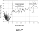
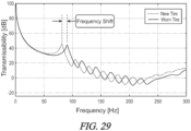
- the method further includes sensing and storing a first set of one or more modal frequencies for the tire at the first stage, responsive to an impact associated with a first modal analysis.
- a subsequent second (e.g., at least partially worn) stage a second set of a corresponding one or more modal frequencies for the tire are sensed, responsive to an impact associated with a second modal analysis. Based on a calculated frequency shift between at least one corresponding modal frequency from each of the first and second sets, a tire wear status of the tire may be estimated at the second stage.
- a mass of the tire is stored at the first stage, wherein the step of estimating the tire wear status at the second stage comprises determining a change in mass of the tire between the first and second stages based on the calculated frequency shift.
- an estimated loss in tire tread is determined in relation to the change in mass of the tire between the first and second stages based on the calculated frequency shift.
- an estimated loss in tire tread may be determined via a retrievable correlation between an observed frequency shift and a change in tire tread for a given tire. The correlation may for example be retrieved from data storage with respect to a given type of tire, or may be developed over time based on historical measurements of changes in tire tread and shifts between corresponding modal frequencies associated with the given type of tire.
- the first and second sets of corresponding modal frequencies are sensed via one or more accelerometers mounted in association with the tire, responsive to excitation of structural modes for the tire.
- the one or more accelerometers may be attached to the tire, for example on the innerliner of the tire, or may be mounted to a spindle of the associated vehicle.
- the tire structural modes are randomly excited during operation of the tire and associated output signals generated by the one or more accelerometers are captured.
- the tire structural modes are excited by controlled impacting of the tire with an external object, such as for example a hammer.
- the tire structural modes are excited by directing movement of the vehicle with respect to one or more predetermined obstacles, such as for example a cleat or speed bump, or a course comprising a sufficiently rough surface.
- An exemplary system in accordance with the fourth embodiment as disclosed herein may implement the vehicle tire wear estimation, for example in view of any one or more of the previously described embodiments and aspects thereof, via a server or server network functionally linked to a data storage network and one or more sensors mounted on the tire and/or the vehicle.
- a fifth embodiment of the computer-implemented method for estimating vehicle tire wear.
- the method of the fifth embodiment includes one or more sensors, associated with a vehicle and/or at least one tire of a plurality of tires supporting the vehicle, generating first data corresponding to real time kinetics of the vehicle and/or the at least one tire.
- the first data is locally processed to generate second data as a reduced subset of the first data, wherein the second data is representative of the first data and comprises any one or more predetermined features extracted therefrom.
- the second data is selectively transmitted to a remote computing system via a communications network, and the remote computing system processes the second data and the any one or more extracted features to estimate a wear characteristic for the at least one tire.
- the second data may comprise a plurality of sequential data frames, each data frame comprising a multidimensional histogram of forces associated with the vehicle and/or the at least one tire.
- the method further comprises selecting a subset of the data frames between at least first and second events and summarizing the data frames over a particular time or a particular distance.
- the summarizing of the data frames is performed via local processing prior to transmittal of the summarized data frames to the remote computing system.
- the subset of the data frames may be transmitted to the remote computing system wherein the summarizing of the data frames is performed via the remote computing system.
- the method further comprises correcting for missing data in a summarized data frame by scaling the summarized data frame by an expected number of data frames with respect to an actual collected number of data frames.
- the extracted features of the second data may comprise wear performance characteristics representative of vehicle driving behavior.
- Processing the first data may comprise performing a Fourier transform on the first data and generating the second data comprising extracted relevant frequencies and associated amplitudes.
- the second data comprises aggregated low frequency CAN data corresponding to an amount of time spent by the vehicle in each of one or more representative driving conditions.
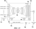
- the first data comprises CAN bus signals.
- the second data is generated via an encoding neural network layer
- the third data is generated via a decoding neural network layer
- a wear calculation layer is appended to the output of the decoding neural network layer and configured to transform the decoded CAN bus signals into instantaneous estimated wear values for the at least one tire.
- the method further comprises comparing the estimated wear values to actual wear values for the at least one tire to generate an error value, and providing the error value as feedback to the neural network layers.
- the selective transmittal of second data is automated and event-based rather than relying upon manual selection for transmittal.
- the selective transmittal of second data may be time-based.
- a method for estimating vehicle tire wear is implemented using one or more sensors associated with a vehicle and/or at least one tire of a plurality of tires supporting the vehicle, wherein first data is generated corresponding to real-time kinetics of the vehicle and/or the at least one tire.
- first data is generated corresponding to real-time kinetics of the vehicle and/or the at least one tire.
- second data is selectively transmitted to a remote computing system via a communications network, wherein the second data is processed further in view of a vehicle model and one or more vehicle route characteristics to generate third data corresponding to the first data, and the third data is further processed to estimate the wear characteristic for the at least one tire.
- the second data further comprises a plurality of sequential data frames, each data frame comprising a multidimensional histogram of forces associated with the vehicle and/or the at least one tire remote computing system.
- the remote computing system reconstructs a vehicle route from the collected vehicle position data and provides vehicle route feedback into the respective multidimensional histograms.
- First data is generated via one or more sensors associated with a vehicle and/or at least one tire of a plurality of tires supporting the vehicle, the first data corresponding to real-time kinetics of the vehicle and/or the at least one tire.
- the first data is processed, via a computing system onboard the vehicle, to generate second data as a reduced subset of the first data, said second data representative of the first data and comprising any one or more predetermined features extracted therefrom.
- the onboard computing system further processes the second data to estimate a wear characteristic for the at least one tire, and generates a notification associated with the estimated wear characteristic to a computing device associated with a vehicle user.
- the step of processing the second data to estimate the wear characteristic for the at least one tire comprises processing the second data to generate third data corresponding to the first data, and further processing the third data to estimate the wear characteristic for the at least one tire.
- the first data comprises CAN bus signals
- the second data is generated via an encoding neural network layer
- the third data is generated via a decoding neural network layer
- a wear calculation layer is appended to the output of the decoding neural network layer and configured to transform the decoded CAN bus signals into instantaneous estimated wear values for the at least one tire.
- Another exemplary aspect of the aforementioned sixth embodiment further comprises comparing the estimated wear values to actual wear values for the at least one tire to generate an error value, and providing the error value as feedback to the neural network layers.
- a method according to the seventh embodiment may include the collecting of vehicle data (e.g., comprising movement data and location data) in association with a first vehicle, and determining a tire wear status for at least one tire associated with the vehicle.
- vehicle data e.g., comprising movement data and location data
- One or more tire traction characteristics for the at least one tire are predicted, based at least on the transmitted vehicle data and the determined tire wear status, and one or more vehicle operation settings are selectively modified based on at least the predicted one or more tire traction characteristics.
- a maximum speed for the vehicle is determined based on at least on the transmitted vehicle data and a determined tire wear status for each tire associated with the vehicle.
- the maximum speed is provided to an autonomous vehicle control system associated with the vehicle.
- the maximum speed may be provided to a driver assistance interface associated with the vehicle.
- one or more tire wear input values are received from a user via a user interface.
- the step of determining the tire wear status comprises receiving one or more tire wear input values generated by one or more sensors mounted in or on a respective tire of the at least one tire.
- the one or more tire wear input values may be generated by a sensor external to the vehicle.
- the step of determining the tire wear status comprises predicting one or more tire wear input values based on at least the transmitted vehicle data and on tire data generated by one or more sensors mounted in or on a respective tire of the at least one tire.
- a system may be provided for performing the method according to the above-referenced seventh embodiment and optionally further according to certain of the exemplary aspects, the system comprising a remote server functionally linked to the vehicle via a communications network, wherein the vehicle data is transmitted from the vehicle to the remote server.
- the remote server is configured to provide the one or more predicted tire traction characteristics to an active safety unit associated with the vehicle, and the active safety unit is configured to modify the one or more vehicle operation settings based on at least the predicted one or more tire traction characteristics.
- the active safety unit may comprise an automated braking system associated with the vehicle, and the remote server is configured to provide one or more parameters of a predicted mu-slip curve associated with a respective tire to the automated braking system.
- a user interface is associated with the remote server and configured to receive one or more tire wear input values from a user.
- the remote server is configured to determine a maximum speed for the vehicle based on at least on the transmitted vehicle data and a determined tire wear status for each tire associated with the vehicle, and provide the maximum speed to a driver assistance interface associated with the vehicle.
- the active safety unit may comprise a collision avoidance system and/or an autonomous vehicle control system.
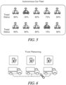
- FIG. 7 Another example of a system may perform the method according to the seventh embodiment as described above, for each of a plurality of vehicles, and optionally further according to certain of the exemplary aspects associated therewith.
- This system comprises a first remote server functionally linked to the vehicle via a communications network, a fleet management server functionally linked to the first remote server, and a vehicle control system associated with each of a plurality of vehicles.
- vehicle data is transmitted from the respective vehicle to the remote server
- the first remote server is configured to provide the one or more predicted tire traction characteristics to the fleet management server
- the fleet management server is configured to interact with the respective vehicle control system for modifying the one or more vehicle operation settings based on at least the predicted one or more tire traction characteristics.
- a user interface is associated with the remote server and/or the fleet management server and/or the vehicle control system, and configured to receive one or more tire wear input values from a user.
- the fleet management server is configured to determine a maximum speed for a given vehicle based on at least on the transmitted vehicle data and a determined tire wear status for each tire associated with the respective vehicle, and provide the maximum speed to the vehicle control system associated with the vehicle.
- the fleet management server is configured to calculate a stopping distance potential for a given vehicle based on at least on the transmitted vehicle data and a determined tire wear status for each tire associated with the vehicle, and provide the stopping distance potential to the vehicle control system associated with the vehicle.
- the fleet management server is further configured to determine an optimal following distance for each of a plurality of vehicles associated with a platoon of vehicles travelling in sequence, and transmit the determined optimal following distance for each one of the plurality of vehicles to the respective vehicle control system.
- the fleet management server is configured to determine a maximum speed and/or stopping distance potential for a given vehicle based on at least on the transmitted vehicle data and a determined tire wear status for each tire associated with the respective vehicle, determine whether the vehicle satisfies threshold traction characteristics, and interact with the vehicle control system to prevent deployment of, or otherwise remove from use, the respective vehicle if the vehicle does not satisfy the threshold traction characteristics.
- a predicted tire wear according to the third embodiment or the fourth embodiment may be provided as an output to a traction model according to the seventh embodiment, complementary to each other without altering the scope of the respective steps or features.
- extracted data according to the fifth embodiment may be provided as input to tire wear models according to one or more other embodiments as disclosed herein.
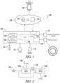
- an exemplary embodiment of the system 100 includes a computing device 102 that is onboard a vehicle and configured to at least obtain data and transmit said data to a remote server 130 and/or perform relevant computations as disclosed herein.
- the computing device may be portable or otherwise modular as part of a distributed vehicle data collection and control system (as shown), or otherwise may be integrally provided with respect to a central vehicle data collection control system (not shown).
- the device may include a processor 104 and memory 106 having program logic 108 residing thereon.
- a system as disclosed herein may implement numerous components distributed across one or more vehicles, for example but not necessarily associated with a fleet management entity, and further a central server or server network in functional communication with each of the vehicles via a communications network.
- the vehicle components may typically include one or more sensors such as, e.g., vehicle body accelerometers, gyroscopes, inertial measurement units (IMU), position sensors such as global positioning system (GPS) transponders 112, tire pressure monitoring system (TPMS) sensor transmitters 118 and associated onboard receivers, or the like, as linked for example to a controller area network (CAN) bus network and providing signals thereby to local processing units.
- GPS global positioning system
- TPMS tire pressure monitoring system
- CAN controller area network
- the illustrated embodiment includes for illustrative purposes, without otherwise limiting the scope of the present invention thereby, an ambient temperature sensor 116, an engine sensor 114 configured for example to provide
- the system may include additional distributed program logic such as for example residing on a fleet management server or other computing device 140, or a user interface of a device resident to the vehicle or associated with a driver thereof (not shown) for real-time notifications (e.g., via a visual and/or audio indicator), with the fleet management device in some embodiments being functionally linked to the onboard device via a communications network.
- System programming information may for example be provided on-board by the driver or from a fleet manager.
- Vehicle and tire sensors may in an embodiment further be provided with unique identifiers, wherein the onboard device processor 104 can distinguish between signals provided from respective sensors on the same vehicle, and further in certain embodiments wherein a central server 130 and/or fleet maintenance supervisor client device 140 may distinguish between signals provided from tires and associated vehicle and/or tire sensors across a plurality of vehicles.
- sensor output values may in various embodiments be associated with a particular tire, a particular vehicle, and/or a particular tire-vehicle system for the purposes of onboard or remote/ downstream data storage and implementation for calculations as disclosed herein.
- the onboard device processor may communicate directly with the hosted server as shown in Fig. 1 , or alternatively the driver's mobile device or truck-mounted computing device may be configured to receive and process/ transmit onboard device output data to the hosted server and/or fleet management server/ device.
- Signals received from a particular vehicle and/or tire sensor may be stored in onboard device memory, or an equivalent data storage unit functionally linked to the onboard device processor, for selective retrieval as needed for calculations according to the method disclosed herein.
- raw data signals from the various signals may be communicated substantially in real time from the vehicle to the server.
- the data may for example be compiled, encoded, and/or summarized for more efficient (e.g., periodic time-based or alternatively defined event-based) transmission from the vehicle to the remote server via an appropriate communications network.
- the vehicle data and/or tire data once transmitted via a communications network to the hosted server 130, may be stored for example in a database 132 associated therewith.
- the server may include or otherwise be associated with tire wear models and tire traction models 134 for selectively retrieving and processing the vehicle data and/or tire data as appropriate inputs.
- the models may be implemented at least in part via execution of a processor, enabling selective retrieval of the vehicle data and/or tire data and further in electronic communication for the input of any additional data or algorithms from a database, lookup table, or the like that is stored in association with the server.
- a system 100 as described above may be implemented for modeling and predicting of tire performance and the provision of feedback based thereon.
- the method may include collecting vehicle data comprising movement data and/or location data for a vehicle and/or at least one tire associated with the vehicle, and determining a current tire wear status in real-time for the at least one tire, based at least in part on the collected data.
- One or more tire performance characteristics are predicted, based at least in part on the determined tire wear status and the collected data.
- Real-time feedback is selectively provided, based on the predicted one or more tire performance characteristics and/or determined current tire wear status.
- an embodiment of a system and method as disclosed herein implements a simplified model 134B of a tire along with the tire's wear state 150 to predict its traction capabilities 160, which is relayed to the user to promote safe driving.
- the simplified model predicts the forces and moments on the tire under a given friction, load, inflation pressure, speed, etc.
- tire wear and “tread wear” may be used herein interchangeably for the purpose of illustration.
- the tread depth 150 must be known/estimated. This may be accomplished by any of several exemplary techniques as follows.
- tire wear (tread) measurements 150 may be made manually by the user and provided as user input into an app or equivalent interface associated with the onboard computing device 102 or directly with the hosted server 130.
- the interface may for example enable direct input of wear values by the user with respect to a selected tire from among a plurality of tires mounted on an identified vehicle.
- the interface may be configured to prompt the user for a captured image or alternative input associated with a tread profile, wherein the wear values may be indirectly determined from the user input.
- tire wear measurements 150 may be made by a tire-mounted sensor and provided to the hosted server, for example without requiring input from the user.
- sensors may for example be mounted directly in the tire tread or on the tire innerliner.
- tire wear measurements 150 may be provided via one or more sensors external to the vehicle and sent to the cloud server 130, again for example without requiring input from the user.
- the one or more sensors may include a drive-over optical sensor comprising a laser emitter configured to capture tire tread information by projecting laser light onto or across a surface of the tire passing over the sensor, and one or more laser receiving elements configured to capture reflected energy and thereby acquire a profile of the tire from which the tire tread may be determined.
- tire wear values 150 may be estimated based on a wear model 134A.
- the wear model may comprise "digital twin" virtual representations of various physical parts, processes or systems wherein digital and physical data is paired and combined with learning systems such as for example neural networks.
- real data 136 from a vehicle and associated location/ route information may be provided to generate a digital representation of the vehicle tire for estimation of tire wear, wherein subsequent comparison of the estimated tire wear with a determined actual tire wear may be implemented as feedback for the machine learning algorithms.
- the wear model 134A may be implemented at the vehicle, for processing via the onboard system 102, or the tire data 138 and/or vehicle data 136 may be processed to provide representative data to the hosted server 130 for remote wear estimation.
- the tire wear status (e.g., tread depth) 150 as shown in Fig. 2 may for example be provided along with certain vehicle data 136 as inputs to the traction model 134B, which may be configured to provide an estimated traction status 160 or one or more traction characteristics 160 for the respective tire.
- the traction model may comprise "digital twin" virtual representations of physical parts, processes or systems wherein digital and physical data are paired and combined with learning systems such as for example artificial neural networks.
- Real vehicle data 136 and/or tire data 138 from a particular tire, vehicle or tire-vehicle system may be provided throughout the life cycle of the respective asset to generate a virtual representation of the vehicle tire for estimation of tire traction, wherein subsequent comparison of the estimated tire traction with a corresponding measured or determined actual tire traction may preferably be implemented as feedback for machine learning algorithms executed at the server level.
- the traction model 134B may in various embodiments utilize the results from prior testing, including for example stopping distance testing results, tire traction testing results, etc., as collected with respect to numerous tire-vehicle systems and associated combinations of values for input parameters (e.g., tire tread, inflation pressure, road surface characteristics, vehicle speed and acceleration, slip rate and angle, normal force, braking pressure and load), wherein a tire traction output may be effectively predicted for a given set of current vehicle data and tire data inputs.
- input parameters e.g., tire tread, inflation pressure, road surface characteristics, vehicle speed and acceleration, slip rate and angle, normal force, braking pressure and load
- the outputs 160 from this traction model 134B may be incorporated into an active safety system.
- an active safety system As previously noted, data is being collected from sensors on the vehicle to feed into the tire wear model 134A which will predict tread depth 150, and this will be fed into the traction model 134B.
- active safety systems may preferably encompass such systems as are generally known to one of skill in the art, including but not limited to examples such as collision avoidance systems, advanced driver-assistance systems (ADAS), anti-lock braking systems (ABS), etc., which can be configured to utilize the traction model output information 160 to achieve optimal performance.
- collision avoidance systems are typically configured to take evasive action, such as automatically engaging the brakes of a host vehicle to avoid or mitigate a potential collision with a target vehicle, and enhanced information regarding the traction capabilities of the tires and accordingly the braking capabilities of the tire-vehicle system are eminently desirable.
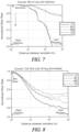
- each graph includes two curves representing the same hypothetical tire at different wear levels. As can be seen, as the tire wears the wet traction performance deteriorates accordingly. During inclement weather, there is a critical speed for worn tires wherein the user risks hydroplaning. With a traction model linked remotely to an onboard display or equivalent user interface, a maximum speed can be communicated to the user to provide safer driving conditions.
- Traction output information such as for example mu-slip curves ( See, e.g., Fig. 4 ) determined according to the respective wear states, may also be fed into the active safety systems for vehicle control implementation and thereby optimized performance.
- the slip ratio represents ((vehicle speed - tire rotation speed) / vehicle speed), wherein a slip ratio of 0% corresponds to a free rolling tire and a slip ratio of 100% corresponds to a locked wheel.
- the active safety system may preferably be configured to determine what, if any, changes could be made to improve tire-vehicle performance characteristics.
- mu-slip curves may be considered to possess relevant shape and location characteristics which influence the ability of an active safety system (e.g., the ABS) to optimize performance, wherein for example the respective peak amplitude "mu" is generally understood to influence the stopping distance (the higher the better).
- Other relevant characteristics of the mu-slip curve shape may include, for example, the slip ratio at the y-axis (mu) peak of the curve, the curvature at or proximate to said peak, the initial slope of the curve, etc.
- a ride-sharing autonomous fleet could use output data 160 from the traction model 134B to disable or otherwise selectively remove vehicles with low tread depth from use during inclement weather, or potentially to limit their maximum speeds.
- a tire with a "worn” state is identified with a hydroplaning critical speed of ⁇ 55 miles per hour at which a peak coefficient of friction falls below the threshold of 0.25, as compared to a tire with a "new" state which may exceed 100 miles per hour without the peak coefficient of friction falling below the same threshold.
- the system may accordingly limit the speed of a vehicle including one or more tires worn to such a state.
- an exemplary autonomous vehicle fleet may comprise numerous vehicles having varying minimum tread status values, wherein the fleet management system may be configured to disable deployment of vehicles falling below a minimum threshold.
- the system may be configured to act upon a minimum tire tread value for each of a plurality of tires associated with a vehicle, or in an embodiment may calculate an aggregated tread status for the plurality of tires for comparison against a minimum threshold.
- a fleet management system may implement the output data 160 from the traction model 134B with respect to a defined platoon of vehicles, such as to better optimize their following distances to achieve maximum fuel savings by better understanding each tire's stopping distance potential.
- minimizing following distances can result in reduced aerodynamic drag for all vehicles in a platoon and thereby improve respective fuel economies, particularly where more than two trucks are included in the platoon, and the disclosed improvements to vehicle platooning methods can desirably facilitate the reduction of following distances beyond a more conventional "one size fits all" approach.
- the most fuel savings may typically be obtained at following distances of less than ⁇ 20 meters, a distance which may be difficult or impossible to maintain during poor weather using conventional techniques for determining traction/ braking capabilities.
- the percentage of time spent platooning may also be increased.
- the active safety or platoon following distance information may be provided to a vehicle braking control system or vehicle platooning control system 120 associated with each respective vehicle.
- vehicle platoon it may be that a single vehicle associated with the platoon receives following distance information and/or certain vehicle control information and passes along the information to other vehicles in the platoon via otherwise conventional vehicle-to-vehicle communication systems and protocols.
- the following distance information provided by the system as disclosed herein may be considered for example a nominal or minimum effective following distance setting based on the respective traction status for vehicles in a platoon, with the understanding that the vehicle platooning control system for a given vehicle or platoon of vehicles may further alter the following distance settings based on monitored traffic events, road conditions, and other ambient conditions that may be outside the scope of the traction status determinations for a given embodiment.
- a first following distance which may be acceptable for a given vehicle under normal driving conditions may necessarily be increased based on monitored real time events such as a change in grade of the road to be traversed, or a heightened risk of braking events by any one or more vehicles in the platoon.
- Components of a vehicle platooning control system 120 are generally known in the art, and may include for example vehicle braking control systems, collision mitigation systems, vehicle-to-vehicle communications, and one or more sensors collectively configured to monitor vehicle data such as a current following distance of the host vehicle (with respect to another vehicle in the platoon or a non-platooning target vehicle), a respective type of said target vehicle, a relative acceleration or deceleration value for the host vehicle, a pressure value with respect to a braking actuator for the host vehicle, etc.
- vehicle data such as a current following distance of the host vehicle (with respect to another vehicle in the platoon or a non-platooning target vehicle), a respective type of said target vehicle, a relative acceleration or deceleration value for the host vehicle, a pressure value with respect to a braking actuator for the host vehicle, etc.
- various embodiments of a method may estimate tire wear values 150 based on a wear model 134A.
- Current wear models require several inputs about the system to accurately project out the wear life of the tire and are developed using very high frequency data.
- transmitting high frequency data from distributed data collectors (e.g., associated with individual vehicles) to centralized computing nodes (e.g., cloud servers) is prohibitively expensive at scale.
- the data presented therein illustrates the effect of signal resolution on wear rate estimations.
- the source data is down sampled to reduce the resolution of the data.
- the down sampling in these examples is performed by simply decimating the source data.
- the source data has a resolution of one meter per sample in the distance domain, or roughly 20 Hz at a speed of 45 mph.
- the x-axis shows a range of one meter per sample up to one thousand meters per sample.
- the y-axis shows the relative error in the wear estimation.
- the data sets respectively correspond to all four tires of a Toyota Camry front wheel drive vehicle, using Turanza EL400 All-Season tires.
- the data is representative of an "average North American driver" on a mixture of city and highway roads, wherein a lower predicted wear rate generally corresponds to a lower accuracy in wear prediction.
- the data is representative of a city taxi fleet, wherein the vast majority of the mileage is in city driving contexts and a higher sampling rate is clearly required relative to the previous data sets.
- the results as shown indicate that simple down sampling of the data is not a reliable, robust, and efficient method of reducing data storage and transmission requirements.
- the minimum resolution needed to achieve good prediction is strongly dependent on the route driven (e.g., city dominated or mixed city and highway) and driving style.
- the minimum resolution needed is also dependent on the tire's position on the vehicle (e.g., left-front, right-front, etc.).
- Exemplary tire wear models 134A as disclosed herein may summarize data from high frequency or alternative low frequency sources into low frequency data, such as route data, which can be transmitted at this lower frequency to the cloud in a cost-effective manner, enabling direct wear modeling.
- improved efficiencies can be achieved with adaptive solutions to make the methods more robust and adaptive to field conditions, e.g., by encoding wear estimation features into a compressed/ reduced dataset.
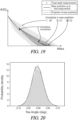
- real-time vehicle kinetics data may be collected from sensors on a vehicle, and then filtered and down sampled into summarized buckets to create a histogram of the relevant forces.
- raw accelerometer data may be down sampled and aggregated into a histogram that is representative of the raw data but at a coarse level.
- the real-time vehicle kinetics data 310 may be compiled into windows 320 of time and/or distance.
- the compiled data may further be aggregated into histogram data frames 330.
- the data frames 330 in the illustrated embodiment are multi-dimensional and contain vehicle body accelerations and vehicle body speed.
- Each point in the histogram represents the time or distance spent in that condition.
- the bins of the histogram may be optimized to maximize wear calculation accuracy and to further minimize data storage and transfer costs, for example implementing simple equally spaced or non-linear bin layouts.
- Figure 10 illustrates an example of a histogram data frame having a first dimension associated with lateral vehicle acceleration, and a second dimension associated with fore-aft vehicle acceleration.
- the individual points in this example are color-coded to represent a time or distance spent in the corresponding condition.
- Histogram data frames 330 allow for flexible and efficient summarization, which can be used on static data in the cloud (after transfer) or on transient data on the vehicle (before the data is transferred).
- Histogram data frames 330 as disclosed in accordance with the present embodiment allow for efficient compensation for missing data.
- a plurality of histogram data frames 330 having a missing subset of data therein may be summarized to generate a partial data frame 430, which may further be corrected by scaling the data frame by the expected number of data frames with respect to the collected number data frames.
- the result (corrected data frame 440) will be an average of the driver's behavior.
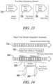
- vehicle kinetics series data 710 may be acquired using one or more sensors on or associated with the vehicle.
- a real-time vehicle to tire model 720 can then be used to simulate tire forces on each tire.
- a model of the tire can be utilized to produce wear rate simulations 730. Both such models can be implemented either in real-time on time/ distance series data or on the aggregated data frames. Simulation results of the model can be stored or transmitted in data frame form.
- Fig. 14 shows real-time simulation of tire forces and transmission of tire force data frames 830.
- the scope of the present embodiment is not necessarily limited thereto, and one of skill in the art may appreciate alternative strategies for various use cases.
- the vehicle kinetics data may be filtered, down sampled and aggregated into a subset of behavioral or "driver severity" values that are representative of how the vehicle is driven. These values are extracted from the raw data to specifically capture predetermined wear performance characteristics of the driver's behavior. The extracted behavioral features are further processed by the downstream (e.g., host server-based) wear model. Behavioral values as features extracted from the raw data prior to transmittal into the cloud may optionally supplement or otherwise complement other forms of summarized or compressed data in accordance with other embodiments as disclosed herein.
- low frequency GPS data from the vehicle may be transmitted to the cloud server, wherein the route is reconstructed with a reverse mapping algorithm and fed into a time series histogram to understand the time spent in various driving conditions (highway, turning, braking, etc.).
- vehicle position data collected or extracted prior to transmittal into the cloud may optionally supplement or otherwise complement other forms of summarized or compressed data in accordance with other embodiments as disclosed herein.
- low frequency CAN data may be aggregated to count the time spent in various driving conditions that is used to calculate wear state.
- feature extraction in the form of event-based driving detection prior to transmittal into the cloud may optionally supplement or otherwise complement other forms of summarized or compressed data in accordance with one or more other embodiments as disclosed herein.
- a neural network autoencoder 900 may be implemented to transform and compress the input CAN bus signals 910 in a first (i.e., encoder) layer 920, and after transmittal of the compressed data into the cloud to further reconstruct the data in a second (i.e., decoder) layer 940 for use by tire wear models to predict tire performance.
- a first vehicle acceleration data stream x-axis acceleration as shown in Fig. 16A
- a second vehicle acceleration data stream y-axis acceleration as shown in Fig. 16B
- a vehicle speed data stream as shown in Fig. 16C
- the raw data and the reconstructed data are overlaid to highlight this accuracy.
- Neural network autoencoders 900 are well known in the art for implementing reductions in data dimensionality, and typically comprise numerous pairs of layers.
- An input layer 910 has a first size, which is reduced via encoding layer 920 with subsequent layers until a middle layer 930 is reached, after which the layer sizes increase via decoding 940 until an output layer 950 having the first size.
- An exemplary use of an autoencoder as disclosed herein may vary from the conventional arrangement in that it further includes a specialized third (i.e., wear estimation) layer 960 that is designed and appended to the second layer 950.
- the specialized third layer 960 is configured to implement wear rate calculations to transform raw CAN bus signals into an instantaneous (actual) wear rate 970.
- the wear layer may comprise proprietary equations containing specific vehicle and tire information relating to the physical system. Because the original vehicle kinetics data signals can be reconstructed with very high accuracy via the first and second layers of the neural network, the additional third (wear specific) layer can similarly be highly accurate.
- This third layer 960 further may enable the first (encoding) layer 920 and second (decoding) layer 940 to be specifically trained over time for estimating wear.
- the encoding and decoding layers learn to capture and store the most essential information for wear calculations. For example, an estimated instantaneous wear rate or predicted wear rate can be compared against an actual wear rate to generate a model error value 980.
- a feedback loop 990 provides the model error values back to the autoencoder for updating of model weights and biases in the first layer 920 and/or second layer 940.
- the third layer 960 will propagate through weights specific to estimating or predicting tire wear.
- appending the third layer 960 to the end of a conventional autoencoder allows the neural network to learn a representation of how to best transform the CAN bus signals to be used for predicting tire wear, whereas a conventional autoencoder would simply learn the best representation for direct regurgitation of the original signals.
- the data is encoded in a manner that enables the decoding layer to produce optimal signals for estimating or predicting tire wear.
- This network architecture may enable the network to learn the physically most important signal features and patterns (peaks, valleys, cross-signal relationships, etc.) for wear and efficiently propagate those features through the network.
- system may be configured to run a Fourier transform on the raw data stream and to extract the most relevant frequencies. These frequencies and accompanying amplitudes may further be used after transmission to the cloud to reconstruct the full raw data state.
- Another exemplary embodiment as disclosed herein, further by reference to Figures 17- 23 relates to the use of Bayesian methods in the characterization and prediction of tire wear.
- the foundation of this approach is the representation of factors contributing to wear (such as driving style, vehicle alignment settings, routes, road surfaces, environmental conditions, tire manufacturing variability, etc.) as probability distributions.
- the rationale behind representing these as probability distributions is that the variations observed in each of these factors are not noise, but truly represent the natural variation that is observed with regards to wear. For example, the same tire being used by an aggressive first driver (who accelerates and brakes hard), relative to a second driver who is more careful, would experience very different tire wear life span. An average representation of these two drivers, when used with a conventional prediction model, would produce a prediction that is insufficient when applied for either case individually.
- predictions made by a wear algorithm will also be probabilistic, i.e., the prediction is also a distribution.
- the prediction is also a distribution.
- Bayesian inference can be used to update these distributions based on observations. Such observations could for example be on the predicted variables (e.g., measurement of tread depth) or input variables (accelerations characterizing driving style). The value of this inference may be in that the model or an associated system as further described below can continue updating the prediction, as well as the confidence in such predictions, over time with respect to for example a specified distance traveled or a time spent traveling using the associated tire(s).
- a process flow may be illustrated by way of comparison to a traditional approach as represented in Fig. 17 .
- Probabilistic distributions of factors such as vehicle wheel and suspension settings relating to tire wear can be generated and fed into a vehicle model, as opposed to specific target or measured values for the same factors.
- One example of such a factor is the camber angle, otherwise known as the angle from the normal of a road surface through the center of a respective wheel (upon which the tire is mounted) to a center line of the wheel.
- Another example of such a factor is toe angle, otherwise known as the angle of the tire with respect to the longitudinal axis of the respective vehicle.
- a tractive or longitudinal force Fx e.g., a tractive or longitudinal force Fx, a lateral force Fy, a vertical or normal force Fz
- moments e.g., overturning torque My, aligning torque Mz
- the force distributions may be fed into a tire wear model wherein tread depth is estimated for a given distance traveled (e.g., 15000 km) according to a baseline value (e.g., 5.8 mm) with a calculated range of uncertainty (e.g., +/-0.3 mm) as opposed to the baseline value alone.
- the probability distribution for the tread depth can subsequently be updated based on observations.
- This update may be implemented using a representation of the Bayes theorem which is shown here: P model observations ⁇ posterior ⁇ P observations model ⁇ likelihood ⁇ P model ⁇ prior
- Bayesian filtering approaches are known in the art to determine the likelihood of a given measurement in view of, e.g., all previous corresponding measurements in a sensor data stream.
- model refers to the parameters of the model and the term “observations” denotes the measurements made on any/all variables involved in the model.
- information relating to the tire wear predictions can be updated over time using actual measurements.
- using this approach we can "correct" the model prediction with every measurement that is taken of a particular tire element and/or vehicle-tire system. For example, if tread depth measurements are periodically collected and transmitted or otherwise compiled for application according to a system and method as disclosed herein, such measurements can be implemented to reduce the uncertainty and enable better predictions over time.
- corrections in tear wear prediction may be provided periodically along with tread depth measurements, wherein an uncertainty in the wear prediction is correspondingly reduced.
- tread depth or an equivalent tire wear-related factor
- potential alternative models or time-series curves may be effectively ruled out or minimized in relevance with respect to a given tire, vehicle-driver-tire system, or the like, and subsequent tire wear estimations may be more accurately provided and with less uncertainty in their respective outcome.
- a wear prediction curve proceeds from a first point (along the y-axis) with a surrounding wear prediction uncertainty U0.
- a corrected wear prediction curve is generated along with a reduced level of uncertainty U1 in the wear prediction.
- the second envelope of uncertainty U1 falls entirely within the first envelope.
- a third and further corrected wear prediction curve is generated, along with a still further reduced level of uncertainty U2 in the wear prediction.
- an exemplary application of a Monte Carlo approach is represented to build probabilistic distributions and use those distributions to generate a distribution of wear progression curves (see, e.g., a wear progression curve for an exemplary front tire as shown in Fig. 22 and a wear progression curve for an exemplary rear tire as shown in Fig. 23 ).
- the approach seeks to determine a corresponding variation in wear progression.
- the inputs were assumed to be independent normal distributions only for the toe angle and the camber angle, wherein everything else is known as single points.
- toe angle and camber angle have been selected for illustration herein, it may be understood that alternative or additional vehicle and/or tire settings may be suitable for the tire wear models and accordingly implemented by the systems and methods as disclosed herein, unless otherwise specifically noted.
- a central curve represents a nominal toe angle/ camber angle setting, wherein the surrounding region represents ten thousand individual wear progression curves corresponding to respective initial wear rates Ew.
- Ew initial wear rates
- an appropriate subset of the individual wear progression curves can be identified with increasing certainty over time, wherein the tire wear status can be accurately predicted with only a relatively small number of actual measurements.
- Periodic measurements associated with tire wear for supplementing the probabilistic distributions may be made directly (manually by users and/or via one or more sensors), and/or estimated in accordance with tire wear models and techniques as otherwise described herein.
- a brush-type model is a simplified tire model with a logical physical background that models the tread elements as independent "brush bristles" extending outward from a base material of the tire (e.g., carcass).
- the brush-type model greatly reduces the complexity of modeling a contact interface between the road surface and the base material, wherein the modeled tread elements can deform in various measurable directions (e.g., longitudinal, lateral, vertical) and can capture the first order effects (tread block stiffening and contact area increasing) that occur in a real tire as it wears.
- the characterization and prediction of tire wear can be implemented using other physics based tire wear models, such as for example finite element analysis (FEA).
- FEA finite element analysis
- An embodiment of the method as disclosed herein further advantageously predicts the absolute wear rate of the tire under a given condition, rather than merely predicting how the wear rate changes as tread depth decreases. This is accomplished at least in part by normalizing a current normalizing the modeled wear rate (e.g., based on periodic or otherwise updated measurements) with respect to the wear rate at the original tread depth (i.e., initial wear rate).
- an exemplary output of the model is illustrated with the normalized wear rate ratio on the y-axis, and the tread loss on the x-axis for two different tires.
- An initial wear rate may be provided as an input to the system, for example but without limitation being provided from an FEA stage, a machine learning model, or the like, the tread depth progression for the entire life of a give tire can be predicted.
- FIG. 25 an exemplary set of results are illustrated when using this predictive method to simulate a wear reference tire compared with measured data of the same tire/vehicle/vehicle-tire system via outdoor wear testing.
- the circular markers indicate the mean tread depth of the control tire test results at each inspection mileage, whereas the underlying solid line represents the predicted tread depth as normalized with respect to an initial tread depth and further via the brush-type model.
- Validation data as further represented in Figure 26 further indicates an acceptable model fit for an exemplary tire wear model such as a hybrid brush-type model as disclosed herein.
- the difference between prediction results and indoor wear test results of a certain control tire was less than 0.25 mm for each mileage for which the tread depth was inspected.
- a hybrid brush-type model as disclosed herein is extremely fast and efficient and can be executed substantially in real-time.
- the test results to date show that the model is accurately predicting wear progression for very different tire designs. Only a relatively small subset of inputs is needed, such as for example the original tread depth and the contact/void area at various tread depths.
- This information can be taken from, e.g., 3D models of the tread pattern, or from a circumferential tread wear imaging system (CTWIST) measurement of a tire, which is typically provided for every tire tested for indoor or outdoor wear.
- CCWIST circumferential tread wear imaging system
- tire-related threshold events can be predicted and implemented for alerts and/or interventions within the scope of the present disclosure.
- the system can identify other services that are recommended for a given vehicle based on time-series inputs received and processed as described above, predicted tire wear, and the like. Examples of such services may include without limitation tire rotation, alignment, inflation, and the like.
- the system may generate the alerts and/or intervention recommendations based on individual thresholds, groups of thresholds, and/or non-threshold algorithmic comparisons with respect to predetermined parameters.
- an optimal type of tire and/or tire parameter can be predicted and implemented for alerts and/or interventions within the scope of the present disclosure.
- the system can identify vehicle applications (higher instances of city driving, higher instances of highway driving, etc.) and/or driving styles based at least in part on the time-series inputs received and processed as described above, predicted tire wear, and the like.
- the system may determine that certain tires are more appropriate for a given vehicle based not only on the type of vehicle but also on the identified vehicle applications and/or driving styles, and further generate the alerts and/or intervention recommendations based at least in part thereon.
- tire information may be provided from one or more sensors mounted on a given tire or an associated vehicle.
- the one or more sensors may be accelerometers mounted directly on, e.g., an inner lining of the tire or a vehicle spindle.
- Output signals from the sensors may be provided to the hosted server, for example without requiring input from the user.
- the modal frequencies can be identified by several methods, including (as previously noted) having an accelerometer attached to the tire, or having an accelerometer attached to the spindle of the vehicle.
- the tire structural modes may also be excited in various manners, including for example a controlled impacting of the tire with an object (such as a hammer, kicking the tire, etc.), electric excitation, running over an obstacle (such as a cleat or speed bump) and/or running the vehicle-tire combination over a rough surface.
- random excitation events may take place during operation of the vehicle-tire combination, wherein output signals from the sensors may be collected and stored, and/or processed to estimate tire wear.
- Figure 27 illustrates an example from a static natural frequency test where a given tire was impacted by a hammer, and an accelerometer was attached to the inner liner of the tire.
- the vibrations associated with the impact produce output signals from the accelerometer with Power Spectral Density (PSD) waveforms as shown.
- PSD Power Spectral Density
- An accelerometer may be configured to provide an output voltage which may be converted by signal processing circuitry into equivalent acceleration signals. These time domain signals may themselves be further transformed into the frequency domain using, e.g., Fast Fourier Transformation.
- the frequency response functions in the power spectrum may typically contain magnitude information, represented in decibel (dB) scale.
- Figure 28A represents results from a cleat impact simulation for a new tire, with a first graph illustrating vertical force variations with respect to time and a second graph illustrating Fast Fourier Transform (FFT) magnitude with respect to a range of frequencies (in Hz).
- FFT Fast Fourier Transform
- Figure 28B represents corresponding results from a cleat impact simulation for the same tire in a worn state, wherein a modal frequency shift is readily observable between the new and worn states.
- Figure 29 represents the results from a transmissibility simulation for new and worn states of a given tire, illustrating transmissibility (in dB) with respect to a spectrum of frequencies, again wherein a modal frequency shift is readily observable between the new and worn states, and wherein the frequency shift may be applied to estimate a change in mass and accordingly a change in tire wear/ tread depth.
- a machine such as a general purpose processor, a digital signal processor (DSP), an application specific integrated circuit (ASIC), a field programmable gate array (FPGA) or other programmable logic device, discrete gate or transistor logic, discrete hardware components, or any combination thereof designed to perform the functions described herein.
- DSP digital signal processor
- ASIC application specific integrated circuit
- FPGA field programmable gate array
- a general purpose processor can be a microprocessor, but in the alternative, the processor can be a controller, microcontroller, or state machine, combinations of the same, or the like.
- a processor can also be implemented as a combination of computing devices, e.g., a combination of a DSP and a microprocessor, a plurality of microprocessors, one or more microprocessors in conjunction with a DSP core, or any other such configuration.
- a software module can reside in RAM memory, flash memory, ROM memory, EPROM memory, EEPROM memory, registers, hard disk, a removable disk, a CD-ROM, or any other form of computer-readable medium known in the art.
- An exemplary computer-readable medium can be coupled to the processor such that the processor can read information from, and write information to, the memory/ storage medium.
- the medium can be integral to the processor.
- the processor and the medium can reside in an ASIC.
- the ASIC can reside in a user terminal.
- the processor and the medium can reside as discrete components in a user terminal.
- vehicle as used herein unless otherwise stated may refer to an automobile, truck, or any equivalent thereof, whether self-propelled or otherwise, as may include one or more tires and therefore require accurate estimation or prediction of tire wear and/or tire traction and potential disabling, replacement, or intervention in the form of for example direct vehicle control adjustments.
- the term "user” as used herein unless otherwise stated may refer to a driver, passenger, mechanic, technician, fleet management personnel, or any other person or entity as may be, e.g., associated with a device having a user interface for providing features and steps as disclosed herein.
Landscapes
- Engineering & Computer Science (AREA)
- Physics & Mathematics (AREA)
- General Physics & Mathematics (AREA)
- Mechanical Engineering (AREA)
- Theoretical Computer Science (AREA)
- Mathematical Physics (AREA)
- General Engineering & Computer Science (AREA)
- Transportation (AREA)
- Data Mining & Analysis (AREA)
- Automation & Control Theory (AREA)
- Evolutionary Computation (AREA)
- Software Systems (AREA)
- Computing Systems (AREA)
- Artificial Intelligence (AREA)
- Pure & Applied Mathematics (AREA)
- Mathematical Optimization (AREA)
- Mathematical Analysis (AREA)
- Computational Mathematics (AREA)
- Computer Hardware Design (AREA)
- Life Sciences & Earth Sciences (AREA)
- Health & Medical Sciences (AREA)
- Biomedical Technology (AREA)
- Biophysics (AREA)
- Computational Linguistics (AREA)
- General Health & Medical Sciences (AREA)
- Molecular Biology (AREA)
- Geometry (AREA)
- Business, Economics & Management (AREA)
- Signal Processing (AREA)
- Computer Networks & Wireless Communication (AREA)
- Human Resources & Organizations (AREA)
- Algebra (AREA)
- General Business, Economics & Management (AREA)
- Economics (AREA)
- Operations Research (AREA)
- Quality & Reliability (AREA)
- Strategic Management (AREA)
- Tourism & Hospitality (AREA)
- Marketing (AREA)
- Entrepreneurship & Innovation (AREA)
Applications Claiming Priority (7)
| Application Number | Priority Date | Filing Date | Title |
|---|---|---|---|
| US201962827339P | 2019-04-01 | 2019-04-01 | |
| US201962843863P | 2019-05-06 | 2019-05-06 | |
| US201962883252P | 2019-08-06 | 2019-08-06 | |
| US201962889684P | 2019-08-21 | 2019-08-21 | |
| US201962911496P | 2019-10-07 | 2019-10-07 | |
| EP20782646.2A EP3946983B1 (de) | 2019-04-01 | 2020-03-30 | System und verfahren zur modellierung und rückkopplung der fahrzeugreifenleistung |
| PCT/US2020/025658 WO2020205703A1 (en) | 2019-04-01 | 2020-03-30 | System and method for vehicle tire performance modeling and feedback |
Related Parent Applications (2)
| Application Number | Title | Priority Date | Filing Date |
|---|---|---|---|
| EP20782646.2A Division EP3946983B1 (de) | 2019-04-01 | 2020-03-30 | System und verfahren zur modellierung und rückkopplung der fahrzeugreifenleistung |
| EP20782646.2A Division-Into EP3946983B1 (de) | 2019-04-01 | 2020-03-30 | System und verfahren zur modellierung und rückkopplung der fahrzeugreifenleistung |
Publications (2)
| Publication Number | Publication Date |
|---|---|
| EP4434770A2 true EP4434770A2 (de) | 2024-09-25 |
| EP4434770A3 EP4434770A3 (de) | 2024-11-27 |
Family
ID=72667114
Family Applications (8)
| Application Number | Title | Priority Date | Filing Date |
|---|---|---|---|
| EP24192381.2A Pending EP4434772A3 (de) | 2019-04-01 | 2020-03-30 | System und verfahren zur vorhersage von reifentraktionsfähigkeiten und aktiven sicherheitsanwendungen |
| EP23195044.5A Active EP4257376B1 (de) | 2019-04-01 | 2020-03-30 | System und verfahren zur modellierung und rückmeldung der leistungsfähigkeit eines fahrzeugreifens |
| EP24192378.8A Pending EP4467361A1 (de) | 2019-04-01 | 2020-03-30 | System und verfahren zur vorhersage des verschleissverlaufs für fahrzeugreifen |
| EP23195043.7A Active EP4261051B1 (de) | 2019-04-01 | 2020-03-30 | System und verfahren zur modellierung und rückmeldung der leistungsfähigkeit eines fahrzeugreifens |
| EP20782646.2A Active EP3946983B1 (de) | 2019-04-01 | 2020-03-30 | System und verfahren zur modellierung und rückkopplung der fahrzeugreifenleistung |
| EP23195041.1A Pending EP4261050A3 (de) | 2019-04-01 | 2020-03-30 | System und verfahren zur modellierung und rückmeldung der leistungsfähigkeit eines fahrzeugreifens |
| EP24192375.4A Pending EP4434770A3 (de) | 2019-04-01 | 2020-03-30 | System und verfahren zur bayesschen inferenz bei der charakterisierung und vorhersage des verschleisses von fahrzeugreifen |
| EP24192377.0A Pending EP4434771A3 (de) | 2019-04-01 | 2020-03-30 | System und verfahren zur vorhersage des verschleissverlaufs für fahrzeugreifen |
Family Applications Before (6)
| Application Number | Title | Priority Date | Filing Date |
|---|---|---|---|
| EP24192381.2A Pending EP4434772A3 (de) | 2019-04-01 | 2020-03-30 | System und verfahren zur vorhersage von reifentraktionsfähigkeiten und aktiven sicherheitsanwendungen |
| EP23195044.5A Active EP4257376B1 (de) | 2019-04-01 | 2020-03-30 | System und verfahren zur modellierung und rückmeldung der leistungsfähigkeit eines fahrzeugreifens |
| EP24192378.8A Pending EP4467361A1 (de) | 2019-04-01 | 2020-03-30 | System und verfahren zur vorhersage des verschleissverlaufs für fahrzeugreifen |
| EP23195043.7A Active EP4261051B1 (de) | 2019-04-01 | 2020-03-30 | System und verfahren zur modellierung und rückmeldung der leistungsfähigkeit eines fahrzeugreifens |
| EP20782646.2A Active EP3946983B1 (de) | 2019-04-01 | 2020-03-30 | System und verfahren zur modellierung und rückkopplung der fahrzeugreifenleistung |
| EP23195041.1A Pending EP4261050A3 (de) | 2019-04-01 | 2020-03-30 | System und verfahren zur modellierung und rückmeldung der leistungsfähigkeit eines fahrzeugreifens |
Family Applications After (1)
| Application Number | Title | Priority Date | Filing Date |
|---|---|---|---|
| EP24192377.0A Pending EP4434771A3 (de) | 2019-04-01 | 2020-03-30 | System und verfahren zur vorhersage des verschleissverlaufs für fahrzeugreifen |
Country Status (5)
| Country | Link |
|---|---|
| US (7) | US12151516B2 (de) |
| EP (8) | EP4434772A3 (de) |
| JP (4) | JP7329068B2 (de) |
| CN (2) | CN116890577A (de) |
| WO (1) | WO2020205703A1 (de) |
Cited By (1)
| Publication number | Priority date | Publication date | Assignee | Title |
|---|---|---|---|---|
| US20240118175A1 (en) * | 2021-04-28 | 2024-04-11 | Bridgestone Americas Tire Operations, Llc | System and method for identifying a tire contact length from radial acceleration signals |
Families Citing this family (74)
| Publication number | Priority date | Publication date | Assignee | Title |
|---|---|---|---|---|
| US10745009B2 (en) * | 2016-12-21 | 2020-08-18 | Samsung Electronics Co., Ltd. | Electronic apparatus for determining a dangerous situation of a vehicle and method of operating the same |
| FR3076047B1 (fr) * | 2017-12-22 | 2021-01-08 | Michelin & Cie | Procede de gestion d'un peloton de camions a partir d'informations relatives aux pneumatiques equipant les camions dudit peloton |
| US11498371B2 (en) * | 2018-12-12 | 2022-11-15 | The Goodyear Tire & Rubber Company | Tire data information system |
| US11289974B2 (en) | 2019-06-07 | 2022-03-29 | Anthony Macaluso | Power generation from vehicle wheel rotation |
| US11837411B2 (en) | 2021-03-22 | 2023-12-05 | Anthony Macaluso | Hypercapacitor switch for controlling energy flow between energy storage devices |
| US11615923B2 (en) | 2019-06-07 | 2023-03-28 | Anthony Macaluso | Methods, systems and apparatus for powering a vehicle |
| US11641572B2 (en) | 2019-06-07 | 2023-05-02 | Anthony Macaluso | Systems and methods for managing a vehicle's energy via a wireless network |
| US11222750B1 (en) | 2021-03-22 | 2022-01-11 | Anthony Macaluso | Hypercapacitor apparatus for storing and providing energy |
| US11432123B2 (en) | 2019-06-07 | 2022-08-30 | Anthony Macaluso | Systems and methods for managing a vehicle's energy via a wireless network |
| US11685276B2 (en) | 2019-06-07 | 2023-06-27 | Anthony Macaluso | Methods and apparatus for powering a vehicle |
| AU2021200226A1 (en) * | 2020-01-28 | 2021-08-12 | The Goodyear Tire & Rubber Company | Method for estimating tire grip |
| DE102020212946A1 (de) * | 2020-10-14 | 2022-04-14 | Robert Bosch Gesellschaft mit beschränkter Haftung | Verfahren zur Steuerung eines Drehmoments zumindest eines Rades |
| US11961052B2 (en) * | 2020-12-15 | 2024-04-16 | Caterpillar Inc. | Systems and methods for wear assessment and part replacement timing optimization |
| CN118884956A (zh) * | 2020-12-17 | 2024-11-01 | 移动眼视力科技有限公司 | 车辆运行安全模型测试系统 |
| JP7427579B2 (ja) | 2020-12-18 | 2024-02-05 | 株式会社ブリヂストン | 車両運用管理システム、車両運用管理プログラムおよび車両運用管理方法 |
| KR20220090651A (ko) * | 2020-12-22 | 2022-06-30 | 현대자동차주식회사 | 자율 주행 제어 장치, 그를 포함하는 차량 시스템, 및 그 방법 |
| WO2022150824A1 (en) * | 2021-01-07 | 2022-07-14 | Bridgestone Americas Tire Operations, Llc | System and method for estimating tire wear using acoustic footprint analysis |
| JP7227997B2 (ja) * | 2021-03-12 | 2023-02-22 | 本田技研工業株式会社 | 決定装置、決定方法、及びプログラム |
| FR3121218A1 (fr) * | 2021-03-29 | 2022-09-30 | Psa Automobiles Sa | Procédé de surveillance de l’usure d’un amortisseur de véhicule automobile |
| JP2022156550A (ja) * | 2021-03-31 | 2022-10-14 | 株式会社トランストロン | 摩耗状態検知装置、摩耗状態検知方法、および摩耗状態検知プログラム |
| US12606156B2 (en) * | 2021-04-07 | 2026-04-21 | Volvo Truck Corporation | Tyre wear rate estimation based on a dynamic tyre model |
| EP4320559A1 (de) * | 2021-04-07 | 2024-02-14 | Sentient Science Corporation | Systeme und verfahren für hybridprognose |
| CN117042987A (zh) | 2021-04-09 | 2023-11-10 | 普利司通美国轮胎运营有限责任公司 | 用于量化机动车辆轮胎的现场使用苛刻度的系统、方法和轮胎老化模型 |
| DE102021204633A1 (de) * | 2021-05-07 | 2022-11-10 | Continental Reifen Deutschland Gmbh | Verfahren und Vorrichtung zur Überwachung der Profiltiefe zumindest eines Fahrzeugreifens |
| DE102021206304A1 (de) * | 2021-06-18 | 2022-12-22 | Continental Reifen Deutschland Gmbh | Verfahren zur Ermittlung einer Profiltiefe eines Fahrzeugreifens |
| JP7602974B2 (ja) * | 2021-06-25 | 2024-12-19 | 株式会社ブリヂストン | タイヤ摩耗予測システム |
| US20230011981A1 (en) * | 2021-07-08 | 2023-01-12 | Volvo Car Corporation | Real-time tire monitoring system |
| DE102021208435A1 (de) * | 2021-08-04 | 2023-02-09 | Continental Reifen Deutschland Gmbh | Verfahren zur Vorhersage eines Profiltiefen-Verlaufes für einen Fahrzeugreifen |
| EP4392271A4 (de) * | 2021-08-27 | 2025-06-18 | Bridgestone Americas Tire Operations, LLC | System und verfahren zur echtzeitschätzung der reifenrollwiderstandskraft |
| JP7797628B2 (ja) * | 2021-08-27 | 2026-01-13 | ブリヂストン アメリカズ タイヤ オペレーションズ、 エルエルシー | タイヤ膨張圧力の関数としてのタイヤに作用する垂直負荷の推定 |
| JP7655824B2 (ja) * | 2021-09-02 | 2025-04-02 | 株式会社ブリヂストン | 車両のエネルギー消費量予測システム、車両のエネルギー消費量予測プログラムおよび予測方法 |
| WO2023049628A1 (en) * | 2021-09-27 | 2023-03-30 | Qualcomm Incorporated | Efficient packet-loss protected data encoding and/or decoding |
| JP7533417B2 (ja) * | 2021-10-07 | 2024-08-14 | トヨタ自動車株式会社 | 情報処理装置、方法、及びプログラム |
| JP7762053B2 (ja) * | 2021-11-30 | 2025-10-29 | 株式会社ブリヂストン | 情報処理装置、情報処理方法、プログラム、運転制御装置、運転制御方法、及びプログラム |
| US20230177612A1 (en) * | 2021-12-02 | 2023-06-08 | International Business Machines Corporation | Dynamic micro-insurance premium value optimization using digital twin based simulation |
| US12263704B2 (en) * | 2021-12-06 | 2025-04-01 | The Goodyear Tire & Rubber Company | Tire irregular wear detection system and method |
| EP4444602A1 (de) * | 2021-12-07 | 2024-10-16 | Volvo Truck Corporation | System und verfahren zur modifizierung der von intelligenten reifen geführten fahrzeuglenkgeometrie |
| EP4194231B1 (de) * | 2021-12-13 | 2026-02-18 | Bridgestone Europe NV/SA | Vorrichtung und verfahren zur berechnung und/oder überwachung der reifenabnutzungsrate eines fahrzeugs |
| JP7708658B2 (ja) * | 2021-12-24 | 2025-07-15 | Toyo Tire株式会社 | タイヤ摩耗量推定システムおよび演算モデル運用方法 |
| US11577606B1 (en) | 2022-03-09 | 2023-02-14 | Anthony Macaluso | Flexible arm generator |
| US11472306B1 (en) | 2022-03-09 | 2022-10-18 | Anthony Macaluso | Electric vehicle charging station |
| US20250209859A1 (en) * | 2022-03-29 | 2025-06-26 | Compagnie Generale Des Etablissements Michelin | Process and system for estimating the remaining useful life of transport vehicle tires on the basis of telematic data |
| CN114862262A (zh) * | 2022-05-30 | 2022-08-05 | 中国第一汽车股份有限公司 | 一种轮胎资源分配方法、装置、设备及存储介质 |
| JP7515189B2 (ja) * | 2022-06-16 | 2024-07-12 | オートペディア カンパニー リミテッド | 深層人工ニューラルネットワークを用いたタイヤトレッド面摩耗判断システム及び方法 |
| EP4299341B1 (de) * | 2022-06-27 | 2025-07-30 | Bridgestone Europe NV/SA | Vorrichtung und verfahren zur berechnung und/oder überwachung der abnutzungsrate eines reifens |
| CN115352460A (zh) * | 2022-08-17 | 2022-11-18 | 珠海格力电器股份有限公司 | 车辆状态的监控方法、装置、存储介质及车载设备 |
| CN115352227B (zh) * | 2022-08-23 | 2023-07-04 | 保隆霍富(上海)电子有限公司 | 一种本车轮胎识别方法及其识别装置、基于天线的本车轮胎识别方法 |
| US12385758B2 (en) | 2022-09-16 | 2025-08-12 | Ford Global Technologies, Llc | Location-synchronous averaging of connected vehicle data |
| CN115257254A (zh) * | 2022-09-29 | 2022-11-01 | 江苏路必达物联网技术有限公司 | 一种基于智能轮胎传感器的车辆轮位识别系统 |
| US12275393B2 (en) | 2022-10-09 | 2025-04-15 | Constructor Technology Ag | System and method for optimising performance of an autonomous race car |
| CN115659503B (zh) * | 2022-10-25 | 2025-07-18 | 中车青岛四方机车车辆股份有限公司 | 一种车轮踏面磨耗加速计算方法及系统 |
| US20260001374A1 (en) * | 2022-10-27 | 2026-01-01 | Bridgestone Americas Tire Operations, Llc | System and method for indirect tire wear modeling and prediction from tire specification |
| CN115862310B (zh) * | 2022-11-30 | 2023-10-20 | 东南大学 | 交通信息不确定环境下网联自动车队稳定性分析方法 |
| US20240192093A1 (en) * | 2022-12-13 | 2024-06-13 | The Goodyear Tire & Rubber Company | System for estimation of remaining tire mileage |
| EP4389463B1 (de) * | 2022-12-19 | 2025-08-20 | Toyota Jidosha Kabushiki Kaisha | Verfahren und vorrichtung zur bestimmung des verschleisses von reifen |
| US12160132B2 (en) | 2023-01-30 | 2024-12-03 | Anthony Macaluso | Matable energy storage devices |
| US11955875B1 (en) | 2023-02-28 | 2024-04-09 | Anthony Macaluso | Vehicle energy generation system |
| US12407219B2 (en) | 2023-02-28 | 2025-09-02 | Anthony Macaluso | Vehicle energy generation system |
| WO2024205821A1 (en) * | 2023-03-24 | 2024-10-03 | Bridgestone Bandag, Llc | Tread compliance system and method |
| CN116070356B (zh) * | 2023-04-06 | 2023-08-08 | 山东玲珑轮胎股份有限公司 | 一种轮胎模型设计方法及系统 |
| CN116448453A (zh) * | 2023-04-14 | 2023-07-18 | 重庆赛力斯新能源汽车设计院有限公司 | 基于封闭场地的驾驶测试方法及系统 |
| DE102023123154A1 (de) | 2023-08-29 | 2025-03-06 | Dr. Ing. H.C. F. Porsche Aktiengesellschaft | Verfahren und Vorrichtung zur Untersuchung der Aerodynamik eines Fahrzeuges |
| CN117073712B (zh) * | 2023-10-17 | 2024-01-30 | 广东省嗒上车物联科技有限公司 | 车辆管理方法、物联网服务器以及计算机可读存储介质 |
| CN117097765B (zh) * | 2023-10-18 | 2024-02-06 | 深圳联鹏高远智能科技有限公司 | 基于物联网的汽车轮胎安全管理方法、系统及介质 |
| CN117217389B (zh) * | 2023-10-26 | 2024-09-20 | 广东省信息网络有限公司 | 一种交互式数据预测方法和系统 |
| US20250153514A1 (en) * | 2023-11-09 | 2025-05-15 | The Goodyear Tire & Rubber Company | Tread wear prediction according to segmentation of tire life |
| CN117252865B (zh) * | 2023-11-14 | 2024-03-19 | 深圳市昊岳科技有限公司 | 一种商用车车辆轮胎状态获取方法及相关装置 |
| EP4556261A1 (de) * | 2023-11-17 | 2025-05-21 | ALSTOM Holdings | Vorhersage einer lebensdauer eines auf einem fahrzeug, insbesondere auf einem spurgebundenen fahrzeug, wie einem einschienenfahrzeug, verbauten reifens |
| CN117382349A (zh) * | 2023-11-29 | 2024-01-12 | 博世汽车部件(苏州)有限公司 | 车辆控制方法和车辆控制单元 |
| US12412430B2 (en) | 2023-12-22 | 2025-09-09 | Anthony Macaluso | Systems and methods for managing a vehicle's energy via a wireless network |
| CN117571341B (zh) * | 2024-01-16 | 2024-05-14 | 山东中亚轮胎试验场有限公司 | 一种轮胎全方位磨损检测系统及方法 |
| US20260077787A1 (en) * | 2024-09-13 | 2026-03-19 | International Business Machines Corporation | Proactive vehicle aquaplaning mitigation system |
| CN119189873B (zh) * | 2024-10-11 | 2025-05-16 | 山东华盛橡胶有限公司 | 一种新能源汽车的轮胎磨损检测预警方法、设备及介质 |
| CN119290432B (zh) * | 2024-12-12 | 2025-04-29 | 山东玲珑轮胎股份有限公司 | 一种轮胎胎面流体压力测试方法以及系统 |
Family Cites Families (88)
| Publication number | Priority date | Publication date | Assignee | Title |
|---|---|---|---|---|
| JP3289375B2 (ja) * | 1993-03-24 | 2002-06-04 | 株式会社デンソー | 車体速度推定装置及び推定車体速度を用いたタイヤ状態検知装置 |
| DE19716586C1 (de) * | 1997-04-21 | 1998-08-06 | Continental Ag | Verfahren zum Ermitteln der Profiltiefe eines Fahrzeugreifens am fahrenden Fahrzeug |
| DE69937702T2 (de) | 1998-04-07 | 2008-12-04 | Pirelli Tyre S.P.A. | Verfahren zur Bestimmung des Strassenverhaltens eines Fahrzeugreifens |
| US6278361B1 (en) * | 1999-12-03 | 2001-08-21 | Trw Inc. | System and method for monitoring vehicle conditions affecting tires |
| JP3892652B2 (ja) | 2000-09-06 | 2007-03-14 | 住友ゴム工業株式会社 | タイヤ解析モデルの作成方法 |
| JP2002131191A (ja) * | 2000-10-18 | 2002-05-09 | Yokohama Rubber Co Ltd:The | 車両タイヤの管理方法 |
| FR2816887B1 (fr) | 2000-11-20 | 2003-03-14 | Dufournier Technologies | Procede et dispositif detecteur d'usure des pneumatiques ou bandes de roulement et surfaces ou zones d'usure analogues |
| US6759952B2 (en) | 2001-07-06 | 2004-07-06 | Trw Inc. | Tire and suspension warning and monitoring system |
| WO2004067307A1 (en) * | 2003-01-27 | 2004-08-12 | Nira Dynamics Ab | Method, system and computer program product for wheel slip control |
| US9818136B1 (en) * | 2003-02-05 | 2017-11-14 | Steven M. Hoffberg | System and method for determining contingent relevance |
| FR2856343B1 (fr) | 2003-06-18 | 2007-04-13 | Michelin Soc Tech | Procede pour predire l'usure d'un pneumatique et systeme pour sa mise en oeuvre |
| JP3853344B2 (ja) * | 2005-02-23 | 2006-12-06 | 横浜ゴム株式会社 | タイヤの摩耗予測方法、タイヤの設計方法、タイヤの製造方法、タイヤの摩耗予測システム及びプログラム |
| JP4984434B2 (ja) * | 2005-05-25 | 2012-07-25 | 横浜ゴム株式会社 | レースタイヤ摩耗予測装置 |
| US8009027B2 (en) * | 2006-05-31 | 2011-08-30 | Infineon Technologies Ag | Contactless sensor systems and methods |
| EP2123487B1 (de) * | 2006-12-13 | 2015-07-29 | Kabushiki Kaisha Bridgestone | Vorrichtung zum schätzen des ausmasses von reifenverschleiss und mit dieser vorrichtung zum schätzen des ausmasses von reifenverschleiss versehenes fahrzeug |
| JP5072463B2 (ja) | 2007-07-11 | 2012-11-14 | 株式会社ブリヂストン | タイヤの摩耗検知方法及びタイヤの摩耗検知装置 |
| ITRE20070128A1 (it) * | 2007-12-19 | 2009-06-20 | Corghi Spa | "metodo e dispositivo per il controllo dell'efficienza di veicoli" |
| JP5620268B2 (ja) | 2008-06-25 | 2014-11-05 | 株式会社ブリヂストン | タイヤ摩耗推定方法及びタイヤ摩耗推定装置 |
| JP4764933B2 (ja) * | 2009-03-06 | 2011-09-07 | 住友ゴム工業株式会社 | タイヤ空気圧低下検出装置及び方法、並びにタイヤ空気圧低下検出プログラム |
| JP4979729B2 (ja) * | 2009-03-19 | 2012-07-18 | 日立建機株式会社 | タイヤ磨耗判定装置を備えた車両 |
| JP5808744B2 (ja) | 2010-07-23 | 2015-11-10 | 株式会社ブリヂストン | タイヤ性能予測方法及びタイヤ設計方法 |
| US8542881B2 (en) * | 2010-07-26 | 2013-09-24 | Nascent Technology, Llc | Computer vision aided automated tire inspection system for in-motion inspection of vehicle tires |
| JP2012027320A (ja) | 2010-07-26 | 2012-02-09 | Enplas Corp | 光ファイバコネクタ |
| FR2970210B1 (fr) * | 2011-01-10 | 2013-08-02 | Peugeot Citroen Automobiles Sa | Systeme de regulation de la vitesse d'un vehicule en fonction de l'etat des pneus |
| US8600917B1 (en) | 2011-04-18 | 2013-12-03 | The Boeing Company | Coupling time evolution model with empirical regression model to estimate mechanical wear |
| US9296263B2 (en) | 2011-12-23 | 2016-03-29 | Prasad Muthukumar | Smart active tyre pressure optimising system |
| US20150143913A1 (en) * | 2012-01-19 | 2015-05-28 | Purdue Research Foundation | Multi-modal sensing for vehicle |
| US9315178B1 (en) | 2012-04-13 | 2016-04-19 | Google Inc. | Model checking for autonomous vehicles |
| JP5956250B2 (ja) | 2012-05-24 | 2016-07-27 | 株式会社ブリヂストン | タイヤ偏摩耗検知方法及びタイヤ偏摩耗検知装置 |
| JP5347054B1 (ja) * | 2012-09-03 | 2013-11-20 | 株式会社ブリヂストン | タイヤケースライフ予測システム |
| US8965691B1 (en) | 2012-10-05 | 2015-02-24 | Google Inc. | Position and direction determination using multiple single-channel encoders |
| US9179628B2 (en) | 2013-06-06 | 2015-11-10 | Monsanto Technology Llc | Soybean variety A1036005 |
| US9050864B2 (en) * | 2013-06-14 | 2015-06-09 | The Goodyear Tire & Rubber Company | Tire wear state estimation system and method |
| US9259976B2 (en) * | 2013-08-12 | 2016-02-16 | The Goodyear Tire & Rubber Company | Torsional mode tire wear state estimation system and method |
| US20150057877A1 (en) * | 2013-08-22 | 2015-02-26 | The Goodyear Tire & Rubber Company | Tire wear state estimation system utilizing cornering stiffness and method |
| US9016116B1 (en) | 2013-10-07 | 2015-04-28 | Infineon Technologies Ag | Extraction of tire characteristics combining direct TPMS and tire resonance analysis |
| DE102013220882B4 (de) * | 2013-10-15 | 2019-05-29 | Continental Automotive Gmbh | Verfahren, Steuergerät und System zum Ermitteln einer Profiltiefe eines Profils zumindest eines Reifens |
| FR3012999B1 (fr) * | 2013-11-14 | 2015-11-13 | Renault Sas | Procede d'aide a la decision par approche bayesienne dans un systeme de surveillance de la pression des pneumatiques d'un vehicule automobile. |
| JP6227385B2 (ja) * | 2013-11-21 | 2017-11-08 | Ntn株式会社 | 自動車用タイヤの摩耗量検知装置 |
| KR101490854B1 (ko) * | 2013-12-13 | 2015-02-09 | 현대오트론 주식회사 | 타이어의 공기압 저하를 감지하는 방법 및 장치 |
| WO2015116036A1 (en) | 2014-01-28 | 2015-08-06 | Hewlett-Packard Development Company, L.P. | Method and system for surface wear determination |
| DE102014205168A1 (de) * | 2014-03-20 | 2015-10-08 | Bayerische Motoren Werke Aktiengesellschaft | Verfahren, Vorrichtung, Computerprogramm und Computerprogrammprodukt zum Bereitstellen von Daten |
| FR3020680B1 (fr) * | 2014-05-02 | 2017-11-24 | Michelin & Cie | Systeme d'evaluation de l'etat d'un pneumatique |
| US9773251B2 (en) | 2014-06-03 | 2017-09-26 | Ford Global Technologies, Llc | Apparatus and system for generating vehicle usage model |
| US10636227B2 (en) * | 2014-06-19 | 2020-04-28 | The Goodyear Tire & Rubber Company | System and method for multiple feature detection and analysis of a rotating tire |
| FR3027254A1 (fr) * | 2014-10-15 | 2016-04-22 | Michelin & Cie | Dispositif de suivi de l’usure d’un pneu |
| US9963132B2 (en) | 2014-11-10 | 2018-05-08 | The Goodyear Tire & Rubber Company | Tire sensor-based vehicle control system optimization and method |
| US9650053B2 (en) * | 2014-12-03 | 2017-05-16 | The Goodyear Tire & Rubber Company | Slip ratio point optimization system and method for vehicle control |
| DE102016000526B4 (de) | 2015-02-05 | 2024-03-21 | HELLA GmbH & Co. KGaA | Verfahren zur Detektion des Verschleißes von sich abnutzenden Reifen eines Fahrzeugs und Fahrzeug mit sich abnutzenden Reifen |
| US9552680B2 (en) * | 2015-02-24 | 2017-01-24 | Ford Global Technologies, Llc | Tire rotation warning |
| CN104765906B (zh) * | 2015-03-03 | 2018-01-16 | 江苏大学 | 一种轮胎外轮廓声学贡献度分析方法 |
| US9688194B2 (en) | 2015-03-26 | 2017-06-27 | Ford Global Technologies, Llc | In-vehicle particulate sensor data analysis |
| KR101683728B1 (ko) * | 2015-06-26 | 2016-12-07 | 현대오트론 주식회사 | 타이어 특성에 따른 타이어 압력 모니터링 장치 및 그 방법 |
| US9995654B2 (en) * | 2015-07-08 | 2018-06-12 | The Goodyear Tire & Rubber Company | Tire and vehicle sensor-based vehicle state estimation system and method |
| US9719886B2 (en) | 2015-07-21 | 2017-08-01 | The Goodyear Tire & Rubber Company | Tread wear estimation system and method |
| US9663115B2 (en) | 2015-10-09 | 2017-05-30 | The Goodyear Tire & Rubber Company | Method for estimating tire forces from CAN-bus accessible sensor inputs |
| EP3159189B1 (de) * | 2015-10-21 | 2018-09-19 | The Goodyear Tire & Rubber Company | System zur indirekten schätzung von reifenverschleiss und verfahren zur schätzung des reifenzustands raddrehzahlsignalmerkmalsextraktion |
| US9821611B2 (en) | 2015-10-21 | 2017-11-21 | The Goodyear Tire & Rubber Company | Indirect tire wear state estimation system |
| US9610810B1 (en) | 2015-10-21 | 2017-04-04 | The Goodyear Tire & Rubber Company | Method of tire state estimation through wheel speed signal feature extraction |
| US9873293B2 (en) * | 2015-10-21 | 2018-01-23 | The Goodyear Tire & Rubber Company | Indirect tire wear state prediction system and method |
| US20170168495A1 (en) * | 2015-12-10 | 2017-06-15 | Uber Technologies, Inc. | Active light sensors for determining expected traction value of a road segment |
| WO2017100797A1 (en) | 2015-12-10 | 2017-06-15 | Uber Technologies, Inc. | Vehicle traction map for autonomous vehicles |
| US10246065B2 (en) | 2015-12-29 | 2019-04-02 | Thunder Power New Energy Vehicle Development Company Limited | Vehicle hazard detection and warning system |
| US9843877B2 (en) | 2015-12-31 | 2017-12-12 | Ebay Inc. | Sound recognition |
| US10406866B2 (en) * | 2016-02-26 | 2019-09-10 | The Goodyear Tire & Rubber Company | Tire sensor for a tire monitoring system |
| US9797703B2 (en) * | 2016-03-07 | 2017-10-24 | Duke University | Non-invasive thickness measurement using resonant frequency shift |
| EP3426505A1 (de) * | 2016-03-09 | 2019-01-16 | Compagnie Générale des Etablissements Michelin | Fahrzeugintegriertes system zur anzeige der erwarteten laufflächenlebensdauer |
| US10424129B2 (en) | 2016-03-28 | 2019-09-24 | Dana Heavy Vehicle Systems Group, Llc | Tire condition telematics system |
| WO2018067720A1 (en) * | 2016-10-05 | 2018-04-12 | Solera Holdings, Inc. | Vehicle tire monitoring systems and methods |
| US10196504B2 (en) | 2016-11-18 | 2019-02-05 | The Goodyear Tire & Rubber Company | Tire with tread for combination of low temperature performance and wet traction |
| WO2018094375A1 (en) * | 2016-11-21 | 2018-05-24 | Nio Usa, Inc. | Method and system for vehicle data optimization |
| US20180154707A1 (en) * | 2016-12-05 | 2018-06-07 | The Goodyear Tire & Rubber Company | Indirect tire pressure and wear state estimation system and method |
| KR102616222B1 (ko) * | 2016-12-22 | 2023-12-21 | 에스케이플래닛 주식회사 | 타이어 마모 확인 시스템, 그 방법 및 컴퓨터 프로그램이 기록된 기록매체 |
| GB2559168B (en) | 2017-01-30 | 2021-01-27 | Jaguar Land Rover Ltd | Controlling movement of a vehicle |
| JP6985805B2 (ja) * | 2017-03-15 | 2021-12-22 | 株式会社ブリヂストン | タイヤメンテナンス支援システム、タイヤメンテナンス支援プログラム及びタイヤメンテナンス支援方法 |
| US20180272813A1 (en) | 2017-03-23 | 2018-09-27 | The Goodyear Tire & Rubber Company | Model based tire wear estimation system and method |
| EP3398825B1 (de) * | 2017-05-03 | 2020-03-11 | Volvo Car Corporation | Verfahren und system zur berechnung einer fahrbahnreibungsschätzung |
| US10603962B2 (en) * | 2017-06-29 | 2020-03-31 | The Goodyear Tire & Rubber Company | Tire wear state estimation system and method |
| US10987977B2 (en) * | 2018-10-26 | 2021-04-27 | Toyota Motor North America, Inc. | Systems and methods for measuring tire wear using embedded image sensors |
| US10889152B2 (en) | 2018-11-23 | 2021-01-12 | Toyota Motor North America, Inc. | Systems, apparatus, and methods to determine vehicle tire wear |
| US11560022B2 (en) * | 2018-12-12 | 2023-01-24 | Tdk Corporation | Rotatable smart wheel systems and methods |
| US11254315B2 (en) * | 2019-03-12 | 2022-02-22 | Mitsubishi Electric Research Laboratories, Inc. | Friction adaptive vehicle control |
| US11897479B2 (en) * | 2019-03-26 | 2024-02-13 | The Penn State Research Foundation | Friction estimation for steering maneuvers for stationary or slow-rolling automobiles |
| JP7194066B2 (ja) * | 2019-03-29 | 2022-12-21 | Toyo Tire株式会社 | 演算モデル生成システム、摩耗量推定システムおよび演算モデル生成方法 |
| US11087566B2 (en) * | 2019-04-16 | 2021-08-10 | Verizon Patent And Licensing Inc. | Determining vehicle service timeframes based on vehicle data |
| US20210300132A1 (en) * | 2020-03-26 | 2021-09-30 | Bridgestone Americas Tire Operations, Llc | Tire state estimation system and method utilizing a physics-based tire model |
| US11945265B2 (en) * | 2021-04-09 | 2024-04-02 | GM Global Technology Operations LLC | Systems and methods for estimating tire wear |
| DE102021205522A1 (de) * | 2021-05-31 | 2022-12-01 | Continental Reifen Deutschland Gmbh | Verfahren zur Bestimmung einer Profiltiefe von einem Fahrzeugreifen |
-
2020
- 2020-03-30 EP EP24192381.2A patent/EP4434772A3/de active Pending
- 2020-03-30 EP EP23195044.5A patent/EP4257376B1/de active Active
- 2020-03-30 EP EP24192378.8A patent/EP4467361A1/de active Pending
- 2020-03-30 EP EP23195043.7A patent/EP4261051B1/de active Active
- 2020-03-30 EP EP20782646.2A patent/EP3946983B1/de active Active
- 2020-03-30 EP EP23195041.1A patent/EP4261050A3/de active Pending
- 2020-03-30 EP EP24192375.4A patent/EP4434770A3/de active Pending
- 2020-03-30 JP JP2021558642A patent/JP7329068B2/ja active Active
- 2020-03-30 CN CN202311098548.XA patent/CN116890577A/zh active Pending
- 2020-03-30 WO PCT/US2020/025658 patent/WO2020205703A1/en not_active Ceased
- 2020-03-30 EP EP24192377.0A patent/EP4434771A3/de active Pending
- 2020-03-30 CN CN202080031191.1A patent/CN113748030B/zh active Active
-
2021
- 2021-09-27 US US17/486,504 patent/US12151516B2/en active Active
- 2021-09-27 US US17/486,520 patent/US20220016941A1/en not_active Abandoned
- 2021-09-27 US US17/486,515 patent/US12084054B2/en active Active
- 2021-09-29 US US17/449,391 patent/US11993260B2/en active Active
- 2021-09-29 US US17/449,394 patent/US20220016938A1/en not_active Abandoned
-
2023
- 2023-08-04 JP JP2023127770A patent/JP7522896B2/ja active Active
-
2024
- 2024-04-11 US US18/633,212 patent/US20240253626A1/en active Pending
- 2024-07-12 JP JP2024112406A patent/JP2024133235A/ja active Pending
- 2024-09-06 US US18/827,033 patent/US20260073741A1/en active Pending
-
2025
- 2025-11-19 JP JP2025198274A patent/JP2026035655A/ja active Pending
Cited By (2)
| Publication number | Priority date | Publication date | Assignee | Title |
|---|---|---|---|---|
| US20240118175A1 (en) * | 2021-04-28 | 2024-04-11 | Bridgestone Americas Tire Operations, Llc | System and method for identifying a tire contact length from radial acceleration signals |
| US12601657B2 (en) * | 2021-04-28 | 2026-04-14 | Bridgestone Americas Tire Operations, Llc | System and method for identifying a tire contact length from radial acceleration signals |
Also Published As
Similar Documents
| Publication | Publication Date | Title |
|---|---|---|
| US12084054B2 (en) | System and method for predicting wear progression for vehicle tires | |
| US10830908B2 (en) | Applying motion sensor data to wheel imbalance detection, tire pressure monitoring, and/or tread depth measurement | |
| US20240246373A1 (en) | System and method for real-time estimation of tire rolling resistance force | |
| US20210300132A1 (en) | Tire state estimation system and method utilizing a physics-based tire model | |
| CN117897284A (zh) | 根据轮胎充气压力估计作用在轮胎上的垂直负载 | |
| US12601657B2 (en) | System and method for identifying a tire contact length from radial acceleration signals | |
| US20240302248A1 (en) | Comprehensive tire health modeling and systems for the development and implementation thereof | |
| EP4274747B1 (de) | System und verfahren zur schätzung des reifenverschleisses unter verwendung von akustischer fussabdruckanalyse |
Legal Events
| Date | Code | Title | Description |
|---|---|---|---|
| PUAI | Public reference made under article 153(3) epc to a published international application that has entered the european phase |
Free format text: ORIGINAL CODE: 0009012 |
|
| STAA | Information on the status of an ep patent application or granted ep patent |
Free format text: STATUS: THE APPLICATION HAS BEEN PUBLISHED |
|
| AC | Divisional application: reference to earlier application |
Ref document number: 3946983 Country of ref document: EP Kind code of ref document: P |
|
| AK | Designated contracting states |
Kind code of ref document: A2 Designated state(s): AL AT BE BG CH CY CZ DE DK EE ES FI FR GB GR HR HU IE IS IT LI LT LU LV MC MK MT NL NO PL PT RO RS SE SI SK SM TR |
|
| PUAL | Search report despatched |
Free format text: ORIGINAL CODE: 0009013 |
|
| AK | Designated contracting states |
Kind code of ref document: A3 Designated state(s): AL AT BE BG CH CY CZ DE DK EE ES FI FR GB GR HR HU IE IS IT LI LT LU LV MC MK MT NL NO PL PT RO RS SE SI SK SM TR |
|
| RIC1 | Information provided on ipc code assigned before grant |
Ipc: B60C 23/04 20060101ALI20241023BHEP Ipc: G06F 30/20 20200101ALI20241023BHEP Ipc: G06F 30/15 20200101ALI20241023BHEP Ipc: G06F 17/00 20190101ALI20241023BHEP Ipc: B60C 99/00 20060101ALI20241023BHEP Ipc: B60C 11/24 20060101AFI20241023BHEP |
|
| STAA | Information on the status of an ep patent application or granted ep patent |
Free format text: STATUS: REQUEST FOR EXAMINATION WAS MADE |
|
| 17P | Request for examination filed |
Effective date: 20250527 |
|
| STAA | Information on the status of an ep patent application or granted ep patent |
Free format text: STATUS: EXAMINATION IS IN PROGRESS |
|
| 17Q | First examination report despatched |
Effective date: 20250930 |
|
| GRAP | Despatch of communication of intention to grant a patent |
Free format text: ORIGINAL CODE: EPIDOSNIGR1 |
|
| STAA | Information on the status of an ep patent application or granted ep patent |
Free format text: STATUS: GRANT OF PATENT IS INTENDED |
|
| INTG | Intention to grant announced |
Effective date: 20260313 |